

Page 1
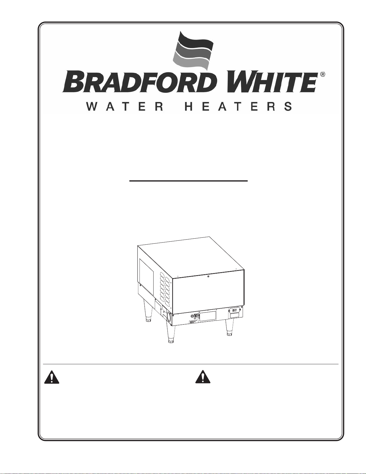
MAGNUM Series
Commercial Electric Booster
Installation and Operating Manual
I&W #07.05.228.00
Do not operate this equipment unless you have
read and understood the contents of this manual!
Failureto follow the instructionscontained in this
manual may result in serious injury or death. This
manual contains important safety information
concerning the maintenance, use, and operation
of this product. If you’re unable to understand the
contents of this manual, please bring it to the
attention of your supervisor. Keep this manual in
a safe location for future reference.
No opere este equipo al menos que haya leído y
comprendido el contenido de este manual!
Cualquier falla en el seguimiento de las
instrucciones contenidas en este manual puede
resultar en un serio lesión o muerte. Este manual
contieneimportante información sobre seguridad
concerniente al mantenimiento, uso y operación
de este producto. Si usted no puede entender el
contenido de este manual por favor pregunte a
su supervisor. Almacenar este manual en una
localización segura para la referencia futura.
Page 2
CONTENTS
NOTICE
CAUTION
WARNING
Important Owner Information ...............................................i
Introduction............................................................................i
Important Safety Information...............................................1
Model Description.................................................................3
Magnum Series Commercial Electric Booster .................3
Specifications........................................................................3
Dimensions......................................................................3
Circuit Breaker and Fused Disconnect Switch Sizes.......4
Capacity...........................................................................5
Installation.............................................................................6
General............................................................................6
Temperature/Pressure Relief Valves ...............................8
Pressure Reducing Valve ................................................8
Temperature/Pressure Gauges .......................................8
Blended Phosphate Water
Treatment System (optional).........................................8
Plumbing Connections.....................................................9
Electrical — All Sizes and Voltages ...............................11
IMPORTANT OWNER INFORMATION
Record the model number, serial number, voltage, and
purchase date of the unit in the spaces below (specification
label located on the unit). Please have this information available
when calling Bradford White for service assistance.
Model No. ____________________________________
Serial No. ____________________________________
Operation.............................................................................12
General..........................................................................12
Maintenance........................................................................13
General..........................................................................13
Thermostat Adjustment..................................................13
Temperature/Pressure Relief Valve ...............................13
High Temperature Limit Safety Switch...........................14
Blended Phosphate Water
Treatment System (optional).......................................14
Troubleshooting Guide ......................................................14
Accessories.........................................................................17
Wiring Diagrams .................................................................18
Limited Warranty.................................................................24
Business Hours: 8:00
Telephone: 800.334.3393 — Technical Service
Additional information can be found by visiting our web site at
www.bradfordwhite.com.
AM to 7:00 PM EST
800.538.2020 — Service Parts
800.531.2111 — Warranty Service
Voltage ______________________________________
Date of Purchase ______________________________
INTRODUCTION
The Bradford White Magnum Series Commercial Electric
Booster water heater is designed for use with commercial
dishwashers to boost the temperature of the regularly available
hot water, usually 110°–150°F (43°–66°C) up to 180°F (82°C).
Water at 180°F (82°C) can be used as sanitizing rinse water in
commercial dishwashers in accordance with Health Codes,
NSF Standard #5 and plumbing codes.
Bradford White Commercial Electric Booster water heaters are
ready for electrical and plumbing service connections, with a
pre-set ambient compensated immersion thermostat and a high
temperature limit switch. The service area is accessible from
the front of the unit, permitting easy installation.
Bradford White Commercial Electric Booster water heaters are
products of extensive research and field testing. The materials
used were selected for maximum durability, attractive
appearance, and optimum performance. Every unit is inspected
and tested thoroughly prior to shipment.
This manual provides the installation, safety, and operating
instructions for Bradford White Commercial Electric Booster
water heaters. Bradford White recommends all installation,
operating, and safety instructions appearing in this manual be
read prior to installation or operation of the unit.
Safety information that appears in this manual is identified by
the following signal word panels:
WARNING indicates a hazardous situation which, if not
avoided, could result in death or serious injury.
CAUTION indicates a hazardous situation which, if not
avoided, could result in minor or moderate injury.
NOTICE is used to address practices not related to
personal injury.
i
Form No. EBOOSTERBWM-1009
Page 3
IMPORTANT SAFETY INFORMATION
WARNING
WARNING
Read the following important safety information before using this equipment to avoid serious injury or death
and to avoid damage to equipment or property.
ELECTRIC SHOCK HAZARD:
• This unit must be installed by qualified, trained
installers. Installation must conform to all local
electrical and plumbing codes. Check with your local
plumbing and electrical inspectors for proper
procedures and codes.
• Turn power OFF at disconnect switch/circuit breaker
and allow unit to cool before performing any
maintenance or cleaning.
• Consult a licensed electrical contractor for proper
electrical installation conforming to local electrical
codes and the National Electrical Code (N.E.C.).
• Unit is not weatherproof. Locate unit indoors where
ambient air temperature is a minimum of 70°F (21°C).
• Do not place aftermarket covers on or over booster
water heater. Doing so can cause temperature and
moisture build-up resulting in premature failure and
electrical shock.
• This unit must be serviced by qualified personnel only.
Service by unqualified personnel may lead to electric
shock or burn.
• Use only Genuine Bradford White Replacement Parts
whenserviceisrequired.Failuretouse GenuineBradford
WhiteReplacementPartswillvoidallwarrantiesand may
subject operators of the equipment to hazardous
electrical voltage, resulting in electrical shock or burn.
GenuineBradfordWhiteReplacementPartsarespecified
to operate safely in the environments in which they are
used.Some aftermarket or genericreplacement parts do
nothavethecharacteristicsthatwillallowthemtooperate
safely in BradfordWhite equipment.
EXPLOSION HAZARD: Do not store or use gasoline or
other flammable vapors or liquids in the vicinity of this or
any other appliance.
Bradford White has always endorsed the use of safety
equipment when using an booster water heater or storagetype water heater. Bradford White booster water heaters
are shipped with a temperature/pressure relief valve at no
extra charge. This valve must be installed into the marked
opening provided in the tank. Valves supplied with this
booster water heater are designed for high temperature
commercial operation. Do not substitute these valves with
valves designed for domestic water heaters.
Temperature/pressure protective equipment should not be
less than a combination temperature/pressure relief valve
certified by a nationally recognized testing laboratory that
maintains periodic inspection of the production of this
equipment and meets the requirements for Relief Valves
and Automatic Shutoff Devices for Hot Water Supply
Systems, ANSI Z21.22-1979. The temperature/pressure
relief valve must be marked with a minimum set pressure
not to exceed the marked hydrostatic test pressure of the
booster heater as noted on the unit specifications.
Do not connect an expansion tank of any type to booster
water heater lines.
FOR INSTALLING COMBINATION TEMPERATURE/
PRESSURE RELIEF VALVES IN ACCORDANCE WITH
AMERICAN NATIONAL STD. Z21.22-1979. Combination
temperature/pressure relief valves with extension
thermostats must be installed so that the temperaturesensing element is immersed in the water within the top 6"
(152 mm) of the tank. They must be installed either in the
hot outlet service line or directly in a tank tapping.
Combination temperature/pressure relief valves that do
not have extension elements must be mounted directly in
a tank tapping located within the top 6" (152 mm) of the
tank, and shall be adequately insulated and located so as
to assure isolation from the flue gas heat or other ambient
conditions that are not indicative of stored water
temperature. TO AVOID WATER DAMAGE OR SCALDING
DUE TO VALVE OPERATION, DRAIN PIPE MUST BE
CONNECTED TO VALVE OUTLET AND RUN TO A SAFE
PLACE OF DISPOSAL. Discharge line must be as short as
possible and be the same size as the valve discharge
connection throughout its entire length. Drain line must
pitch downward from the valve and must terminate
between 1-1/2" (38 mm) and 6" (152 mm) above the floor
drain where any discharge will be clearly visible. The drain
line shall terminate plain, not threaded, with material
serviceable for temperatures up to 250°F (121°C) or
greater. Excessive length, over 30' (9144 mm), or use of
more than four elbows can cause a restriction and reduce
the discharge capacity of the valve. No shut-off valve shall
be installed between the relief valve and tank, or in the
drain line. Valve lever must be tripped periodically to
assure that waterways are clear.This device is designated
for emergency safety relief and shall not be used as an
operating control. The valves are set to relieve at 150 psi
(1034 kPa) or when water temperature reaches 210°F
(99°C). Read tag on valve for additional information.
Inspect combination temperature/pressure relief valve at
least once every two to four years, depending on local
water conditions. Contact a licensed plumber or qualified
service technician for inspection. Replace valve, if
necessary. DO NOT attempt to self-inspect valve.
Use only plumbing material suitable for a minimum water
temperature of 200°F (93°C). Materials used must meet
National Sanitation Foundation (NSF) specifications and
all local plumbing codes and regulations.
Install booster water heater in horizontal position with
base parallel to the floor and inlet connection at the lowest
point. If installing with legs, mount on floor. If installing
with slide brackets, mount under dish table. DO NOT
mount on walls or in ceiling. Unit must be accessible for
service. Improper installation could create an unsafe
condition.
Valves supplied with this booster water heater are
designed for high temperature commercial operation. Do
not substitute these valves with valves designed for
domestic water heaters.
Form No. EBOOSTERBWM-1009
1
Page 4
IMPORTANT SAFETY INFORMATION
WARNING
CAUTION
CAUTION
NOTICE
Read the following important safety information before using this equipment to avoid serious injury or death
and to avoid damage to equipment or property.
Units are equipped with a high temperature limit safety
switch that will shut off power if the unit overheats.
Contact an Authorized Service Agent if high temperature
limit safety switch cannot be reset or continues to trip.
Install booster water heater as close as possible to the
commercial dish machine. Employ recirculation if
distance between booster and commercial dish machine
exceeds National Sanitation Foundation (NSF)
specifications of five (5) linear feet (1524 mm).
Make sure the dish table is strong enough to support the
weight of the booster heater and water when installing
with slide mounting brackets.
Follow standard welding safety and operational
procedures when attaching sliderails to bottom of dish
table.
This product contains fiberglass, a product known to the
state of California to cause cancer, birth defects or other
reproductive harm.
It is essential to recognize that even though a booster
water heater may be installed properly and approved
initially, there always exists the possibility that unknowing
individuals might alter or change the installation in a
manner that would render it unsafe. Therefore, it is
important that all safety programs provide some
mechanism to assure that these installations are
inspected periodically.
This unit has no “user-serviceable” parts. If service is
required on this unit, contact an Authorized Service Agent
or the Bradford White Service Department.
BURN HAZARD:
• Water in unit is very hot. Wear protective gloves and
proper attire when operating to avoid injury.
• Some exterior surfaces on unit will get hot. Avoid
unnecessary contact with unit.
• Valves supplied with this booster water heater are
designed for high temperature commercial operation.
Do not substitute these valves with valves designed for
domestic water heaters.
Do not use anti-siphon or check valves on incoming water
line.
Do not connect booster water heater directly to a boiler or
furnace coil or any other uncontrolled temperature
source. The booster heater thermostat could be damaged
causing unit to overheat.
Do not connect booster water heater to domestic
(consumer) dishwashers or other domestic utilized
equipment. Hot water from booster heater may damage
domestic equipment resulting in a hazardous condition.
Do not store any materials or items on or against the
housing of the booster water heater.
Bradford White requires that two temperature/pressure
gauges be installed to assure proper operation. Install one
in the supply line before the pressure reducing valve and
one in the outlet line as close to the booster water heater
as possible. This provides a visual check of the water
temperature and pressure before and after the water
heater.
If water supply pressure to the booster water heater inlet
is over 20 psi (138 kPa) during flow, install a commercialgrade pressure reducing valve with built-in bypass for
proper operation of dish machine rinse nozzles.
NOTE: The pressure reducing valve must be the type
equipped with a high pressure bypass, like the valve
supplied with this booster water heater.
DO NOT turn on power to the booster water heater until
tank has been filled with water and all air has been vented
through dish machine rinse nozzle. The heating elements
will burn out in seconds if operated when they are not
immersed in water.
ALWAYS drain booster water heater with power to the unit
off or element burnout could occur.
Use dielectric couplings when connecting dissimilar
metals, such as galvanized to copper. This will prevent
electrolysis or premature plumbing damage.
DO NOT turn or adjust inlet water connection on Magnum
Series booster water heaters. Doing so will change the
internal water flow.
Do not back out or loosen any pipe fittings. Doing so may
cause leaks.
Do not lay unit on the side with the control panel. Damage
to the unit could occur.
Incoming water in excess of 3 grains of hardness per
gallon (GPG) (0.75 grains of hardness per liter [GPL]) must
be treated and softened before being supplied to booster
heater(s). Water containing over 3 GPG (0.75 GPL) will
decrease efficiency, increase energy use, and reduce the
operating life of the unit through increased lime build-up.
Product failure caused by liming or sediment buildup is
not covered under warranty.
Do not use deionized or reverse osmosis (R.O.) treated
water in booster water heaters. Damage to booster heater
may occur.
Connect electric booster water heater to the same power
supply as indicated on the specification decal only.
Connecting unit to an incorrect power supply voids the
product warranty and will damage the equipment.
2
Form No. EBOOSTERBWM-1009
Page 5
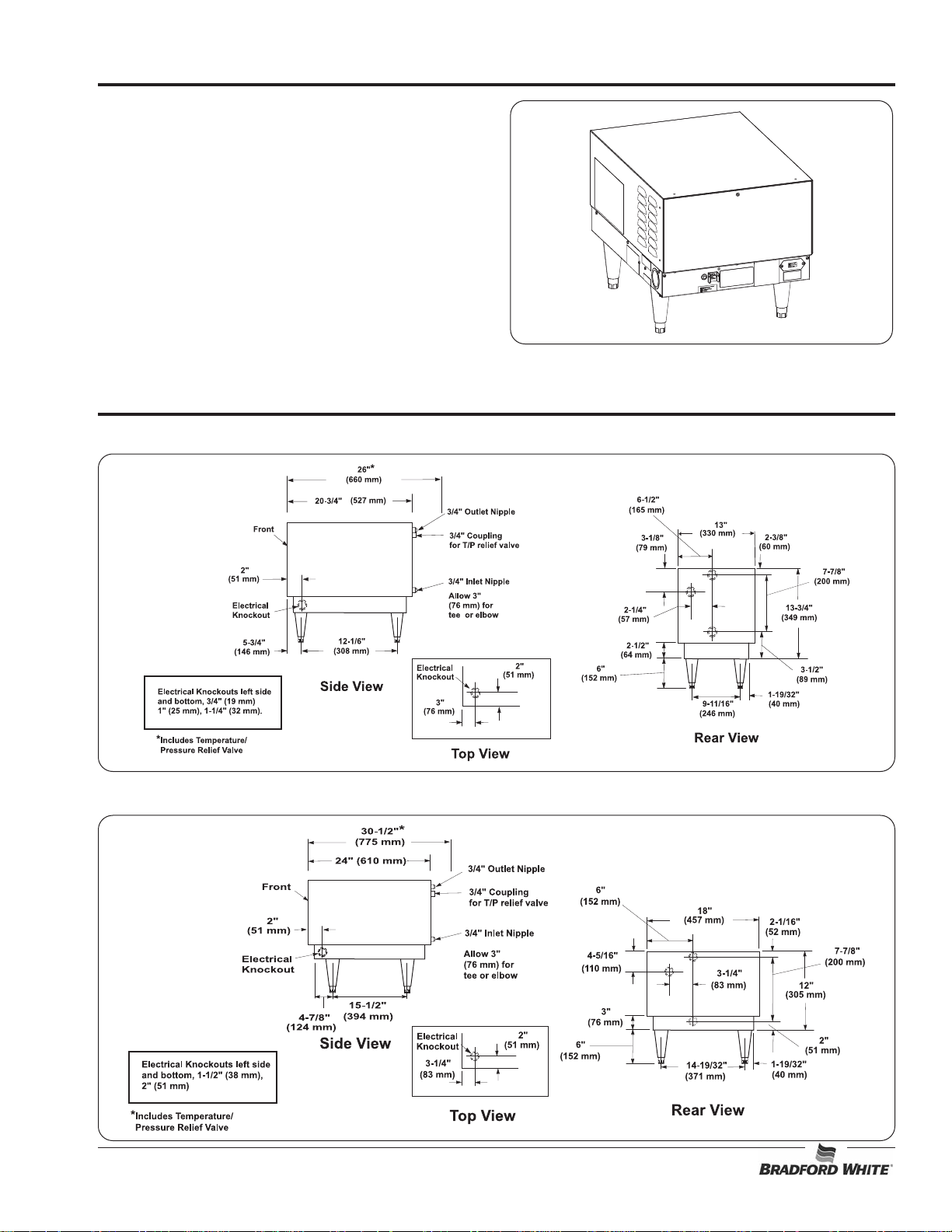
MagnumSeries CommercialElectric Booster
The Magnum Series Commercial Electric Booster water heater
includes a booster heater with low-water cut-off system,
temperature/pressure relief valve, pressure reducing valve with
built-in high pressure bypass, two temperature/pressure gauges
and a high temperature limit safety switch.
Magnum Series models feature a Castone
limited warranty, an ON/OFF switch, an indicator light and either
6" (152 mm) legs or slide mounting brackets for mounting under
a dish table. Magnum Series units have a capacity of 6 gallons
(23 liters) and provide up to 573 gph (2169 lph) of sanitizing
rinse water based on a 40°F (22°C) temperature rise.
®
tank with a 5 year
Dimensions — Magnum Series 6 to 18 kW
MODEL DESCRIPTION
Figure 1. Magnum Series Commercial Electric Booster
SPECIFICATIONS
Dimensions — Magnum Series 24 to 57 kW
Form No. EBOOSTERBWM-1009
3
Page 6

SPECIFICATIONS
Circuit Breaker and Fused Disconnect Switch Sizes — 6 to 30 kW
Model kW Volts Phase Amp Draw Breaker or Copper Conduit
L1 L2 L3 Fuse Size Wire Size Size
LI663CFC 6 208 1 29 29 - 40 8 1/2" (13 mm)
LI663CFD 6 208 3 14 25 14 40 8 1/2" (13 mm)
LI663CFE 6 240 1 25 25 - 40 8 1/2" (13 mm)
LI663CFF 6 240 3 13 22 13 30 10 1/2" (13 mm)
LI663CFM 6 480 3611 6 15 14 1/2" (13 mm)
LI693CFC 9 208 1 43 43 - 60 6 1/2" (13 mm)
LI693CFD 9 208 3 22 38 22 50 8 1/2" (13 mm)
LI693CFE 9 240 1 38 38 - 50 8 1/2" (13 mm)
LI693CFF 9 240 3 19 33 19 50 8 1/2" (13 mm)
LI693CFM 9 480 3916 9 20 12 1/2" (13 mm)
LI6123CFC 12 208 1 58 58 - 90 3 1" (25 mm)
LI6123CFD 12 208 3 33 33 33 50 8 1/2" (13 mm)
LI6123CFE 12 240 1 50 50 - 70 6 1/2" (13 mm)
LI6123CFF 12 240 3 29 29 29 40 8 1/2" (13 mm)
LI6123CFM 12 480 3 14.5 14.5 14.5 20 12 1/2" (13 mm)
LI6153CFC 15 208 1 72 72 - 90 3 1" (25 mm)
LI6153CFD 15 208 3 41.7 41.7 41.7 60 6 3/4" (19 mm)
LI6153CFE 15 240 1 62.5 62.5 - 90 3 1" (25 mm)
LI6153CFF 15 240 3 36.1 36.1 36.1 50 8 1/2" (13 mm)
LI6153CFM 15 480 3 18.1 18.1 18.1 30 10 1/2" (13 mm)
LI6183CFC 18 208 1 86.5 86.5 - 125 1 1-1/4" (32 mm)
LI6183CFE 18 240 1 75 75 - 100 3 1" (25 mm)
LI6183CFF 18 240 3 43.4 43.4 43.4 60 6 3/4" (19 mm)
LI6183CFM 18 480 3 21.7 21.7 21.7 30 10 1/2" (13 mm)
LI6243CFC 24 208 1 115.4 115.4 - 150 1/0 1-1/4" (32 mm)
LI6243CFD 24 208 3 66.7 66.7 66.7 90 3 1" (25 mm)
LI6243CFE 24 240 1 100 100 - 125 1 1-1/4" (32 mm)
LI6243CFF 24 240 3 57.8 57.8 57.8 90 3 1-1/4" (32 mm)
LI6243CFM 24 480 3 29.9 29.9 29.9 40 8 1/2" (13 mm)
LI6303CFC 30 208 1 144 144 - 200 3/0 1-1/2" (38 mm)
LI6303CFD 30 208 3 83.3 83.3 83.3 125 1 1-1/4" (32 mm)
LI6303CFE 30 240 1 125 125 - 175 2/0 1-1/2" (38 mm)
LI6303CFF 30 240 3 72.3 72.3 72.3 100 3 1" (25 mm)
LI6303CFM 30 480 3 36 36 36 50 8 1/2" (13 mm)
Wire size is based on THHN wire for branch circuit protection at .91 derate factor. Circuit breakers and fused disconnects are to
be mounted remote and wired by contractor. Sizes are based on the 2002 NEC table 310-16. Conduit size based on conductors
plus ground wire sizing per Table C1 from Appendix C.
Only 6 and 9 kW models can be field converted to single- or three-phase (open delta on 3-phase). Check wiring diagram supplied
with the unit when converting the phase of a unit. Larger branch circuit required than for balanced 3-phase of equal kW. Balanced
3-phase available, consult factory.
NOTE: 250 kcmil maximum wire size for terminal block.
WARNING! Consult a licensed electrical contractor for proper electrical installation conforming to local electrical codes
and the National Electrical Code (N.E.C.).
4
Form No. EBOOSTERBWM-1009
Page 7
SPECIFICATIONS
Circuit Breaker and Fused Disconnect Switch Sizes — 36 to 57 kW
Model kW Volts Phase Amp Draw Breaker or Copper Conduit
L1 L2 L3 Fuse Size Wire Size Size
LI6363CFC 36 208 1 173 173 - 225 4/0 1-1/2" (38 mm)
LI6363CFD 36 208 3 100 100 100 125 1 1-1/4" (32 mm)
LI6363CFE 36 240 1 150 150 - 200 3/0 1-1/2" (38 mm)
LI6363CFF 36 240 3 86.7 86.7 86.7 125 1 1-1/4" (32 mm)
LI6363CFM 36 480 3 43.3 43.3 43.3 60 6 3/4" (19 mm)
LI6453CFD 45 208 3 125 125 125 175 2/0 1-1/2" (38 mm)
LI6453CFE 45 240 1 188 188 - 250 250 kcmil 2" (51 mm)
LI6453CFF 45 240 3 108 108 108 150 1/0 1-1/4" (32 mm)
LI6453CFM 45 480 3 54 54 54 70 4 1" (25 mm)
LI6543CFD 54 208 3 150 150 150 200 3/0 2" (51 mm)
LI6543CFF 54 240 3 130 130 130 175 2/0 1-1/2" (38 mm)
LI6543CFM 54 480 3 65 65 65 90 3 1" (25 mm)
LI6573CFD 57 208 3 158.4 158.4 158.4 200 3/0 2" (51 mm)
LI6573CFF 57 240 3 137.3 137.3 137.3 175 2/0 1-1/2" (38 mm)
LI6573CFM 57 480 3 68.6 68.6 68.6 90 3 1" (25 mm)
Wire size is based on THHN wire for branch circuit protection at .91 derate factor. Circuit breakers and fused disconnects are to
be mounted remote and wired by contractor. Sizes are based on the 2002 NEC table 310-16. Conduit size based on conductors
plus ground wire sizing per Table C1 from Appendix C.
NOTE: 250 kcmil maximum wire size for terminal block.
WARNING! Consult a licensed electrical contractor for proper electrical installation conforming to local electrical codes
and the National Electrical Code (N.E.C.).
Capacity
Model kW 40°F (22°C) Rise 70°F (39°C) Rise Shipping Weight
LI663XXX Models 6 60 gph (227 lph) 34 gph (129 lph) 118 lbs. (54 kg)
LI693XXX Models 9 90 gph (341 lph) 52 gph (197 lph) 118 lbs. (54 kg)
LI6123XXX Models 12 120 gph (454 lph) 69 gph (261 lph) 120 lbs. (54 kg)
LI6153XXX Models 15 151 gph (572 lph) 86 gph (326 lph) 120 lbs. (54 kg)
LI6183XXX Models 18 181 gph (685 lph) 103 gph (390 lph) 120 lbs. (54 kg)
LI6243XXX Models 24 241 gph (912 lph) 138 gph (522 lph) 142 lbs. (64 kg)
LI6303XXX Models 30 301 gph (1139 lph) 172 gph (651 lph) 142 lbs. (64 kg)
LI6363XXX Models 36 361 gph (1367 lph) 206 gph (780 lph) 142 lbs. (64 kg)
LI6453XXX Models 45 452 gph (1711 lph) 258 gph (977 lph) 142 lbs. (64 kg)
LI6543XXX Models 54 542 gph (2052 lph) 310 gph (1174 lph) 142 lbs. (64 kg)
LI6573XXX Models 57 573 gph (2169 lph) 326 gph (1234 lph) 142 lbs. (64 kg)
NOTE: Storage capacity is 6 gallons (23 liters).
Form No. EBOOSTERBWM-1009
5
Page 8
INSTALLATION
NOTICE
WARNING
WARNING
Models 24–58 kW
20-1/4″
(514 mm)
Weld slide rail
to bottom of
dish table.
Models 6–18 kW
15-1/4″
(387 mm)
Fasten slide brackets
to booster water heater
sides.
General
For the most effective operation, install the booster water heater
as close as possible to the commercial dish machine. The
location must have a solid foundation or strong table/counter
construction along with being clean and dry. Adequate front
clearance is required to allow for accessibility to the control
compartment. Location must have adequate clearance to allow
for inspection, testing, or replacement of temperature/pressure
relief valve.
ELECTRIC SHOCK HAZARD:
• This unit must be installed by qualified, trained
installers. Installation must conform to all local
electrical and plumbing codes. Check with your local
plumbing and electrical inspectors for proper
procedures and codes.
• Consult a licensed electrical contractor for proper
electrical installation conforming to local electrical
codes and the National Electrical Code (N.E.C.).
• Unit is not weatherproof. Locate unit indoors where
ambient air temperature is a minimum of 70°F (21°C).
• Do not place aftermarket covers on or over booster
water heater. Doing so can cause temperature and
moisture build-up resulting in premature failure and
electrical shock.
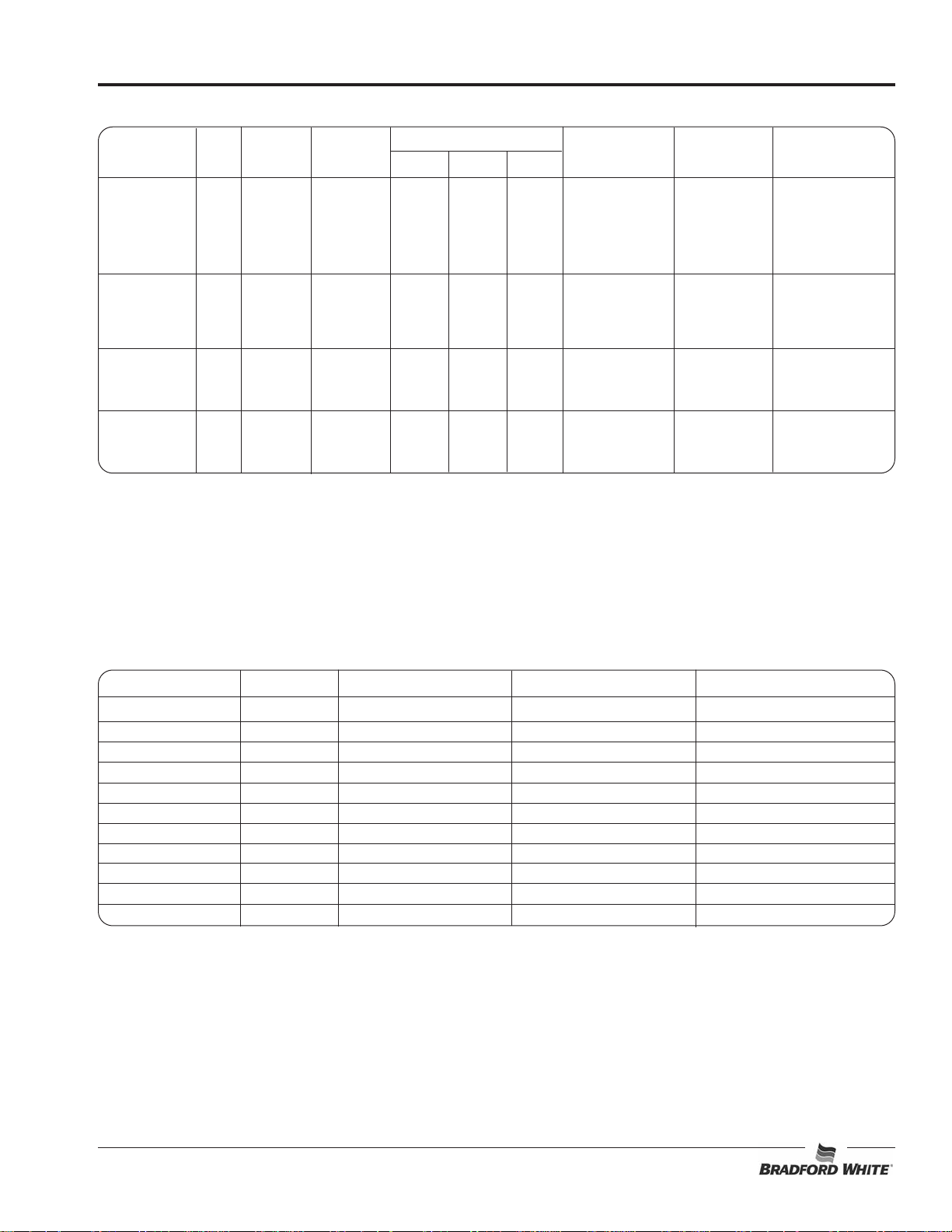
Figure 2. Installing the Legs
NOTE: If unit is not level, use an adjustable open-end wrench
to adjust the foot of each leg until unit is level. Each leg
is adjustable from 6″ (152 mm) to 7″ (178 mm).
5. If installing the unit with mounting brackets, use the
following procedure:
Make sure the dish table is strong enough to support the
weight of the booster heater and water when installing
with slide mounting brackets.
Follow standard welding safety and operational
procedures when attaching sliderails to bottom of dish
table.
• Space slide rails as shown below, and weld the rails to
the bottom of the dish table.
Install booster water heater as close as possible to the
commercial dishwasher. Employ recirculation if distance
between booster and commercial dishwasher exceeds
National Sanitation Foundation (NSF) specifications of
five (5) linear feet (1524 mm).
Install booster water heater in horizontal position with
base parallel to the floor and inlet connection at the lowest
point. If installing with legs, mount on floor. If installing
with slide brackets, mount under dish table. DO NOT
mount on walls or in ceiling. Unit must be accessible for
service. Improper installation could create an unsafe
condition.
Booster Heaters are shipped with most components preassembled. Care should be taken when unpacking shipping
carton to avoid damage to unit and components enclosed.
Components are shipped with the heater unit (see Figure 4).
1. Remove the unit from the carton.
2. Remove the information packet.
3. Remove tape and protective packaging from all surfaces
of unit.
4. If the unit is equipped with legs, carefully lay the unit on its
side and install the four legs as shown in Figure 2.
Do not lay unit on the side with the control panel. Damage
to the unit could occur.
Figure 3. Attaching the Slide Rails to the Dish Table
• Using the Bradford White slide brackets as a template,
drill 1/8″ (3 mm) holes into the sides of the heater jacket.
• Attach slide brackets
to the sides of the
booster water heater
with 3/4 x 8 sheet
metal screws
supplied.
• Slide the booster
water heater onto
slide rails under dish
table.
6
Form No. EBOOSTERBWM-1009
Page 9

INSTALLATION
Legs
Plastic Leg
Stainless Steel Leg
Mounting Brackets with Hardware
A set of mounting brackets or a set of legs are supplied with
each booster water heater.
Pressure Reducing Valve
One pressure reducing valve with built-in bypass supplied
with all booster water heaters.
Shock Absorber
An optional
heaters.
shock absorber is available for all booster water
Temperature/Pressure Gauge
Two temperature/pressure gauges are supplied with all
booster water heaters.
Temperature/Pressure Relief Valve
One temperature/pressure relief valve supplied with all
booster heaters.
Blended Phosphate Water Treatment System
An optional
available for all booster water heaters.
blended phosphate water treatment system is
Back Pressure Relief Valve
An optional
booster water heaters.
back pressure relief valve is available for all
Figure 4. Components Shipped with the Magnum Series Commercial Electric Booster
Form No. EBOOSTERBWM-1009
7
Page 10

INSTALLATION
CAUTION
WARNING
CAUTION
CAUTION
Temperature/Pressure Relief Valves
For protection against excessive pressures and temperatures in
the booster heater, install temperature/pressure protective
equipment required by local codes. The temperature/pressure
relief valve supplied with this booster water heater is
constructed with brass working parts and heat resistant silicone
seat discs.
Temperature/pressure protective equipment should not be
less than a combination temperature/pressure relief valve
certified by a nationally recognized testing laboratory that
maintains periodic inspection of the production of this
equipment and meets the requirements for Relief Valves
and Automatic Shutoff Devices for Hot Water Supply
Systems, ANSI Z21.22-1979. The temperature/pressure
relief valve must be marked with a minimum set pressure
not to exceed the marked hydrostatic test pressure of the
booster heater as noted on the unit specifications.
FOR INSTALLING COMBINATION TEMPERATURE/
PRESSURE RELIEF VALVES IN ACCORDANCE WITH
AMERICAN NATIONAL STD. Z21.22-1979. Combination
temperature/pressure relief valves with extension
thermostats must be installed so that the temperaturesensing element is immersed in the water within the top 6"
(152 mm) of the tank. They must be installed either in the
hot outlet service line or directly in a tank tapping.
Combination temperature/pressure relief valves that do
not have extension elements must be mounted directly in
a tank tapping located within the top 6" (152 mm) of the
tank, and shall be adequately insulated and located so as
to assure isolation from the flue gas heat or other ambient
conditions that are not indicative of stored water
temperature. TO AVOID WATER DAMAGE OR SCALDING
DUE TO VALVE OPERATION, DRAIN PIPE MUST BE
CONNECTED TO VALVE OUTLET AND RUN TO A SAFE
PLACE OF DISPOSAL. Discharge line must be as short as
possible and be the same size as the valve discharge
connection throughout its entire length. Drain line must
pitch downward from the valve and must terminate
between 1-1/2" (38 mm) and 6" (152 mm) above the floor
drain where any discharge will be clearly visible. The drain
line shall terminate plain, not threaded, with material
serviceable for temperatures up to 250°F (121°C) or
greater. Excessive length, over 30' (9144 mm), or use of
more than four elbows can cause a restriction and reduce
the discharge capacity of the valve. No shut-off valve shall
be installed between the relief valve and tank, or in the
drain line. Valve lever must be tripped periodically to
assure that waterways are clear.This device is designated
for emergency safety relief and shall not be used as an
operating control. The valves are set to relieve at 150 psi
(1034 kPa) or when water temperature reaches 210°F
(99°C). Read tag on valve for additional information.
Pressure Reducing Valve
If water supply pressure to the booster water heater inlet
is over 20 psi (138 kPa) during flow, install a commercialgrade pressure reducing valve with built-in bypass for
proper operation of dish machine rinse nozzles.
NOTE: The pressure reducing valve must be the type
equipped with a high pressure bypass like the valve
supplied with this booster water heater.
Proper operation of the commercial dish machine rinse nozzles
requires that available water pressure at the rinse nozzle be
between 15 and 25 psi (103 and 172 kPa) when the nozzle is
operated. 20 psi (138 kPa) is recommended. If water pressure
available to the booster water heater inlet is over 20 psi
(138 kPa), a pressure reducing valve must be installed in the hot
water supply line to the booster water heater and adjusted to
deliver 20 psi (138 kPa) flow pressure.
The valve supplied with the unit has a built-in high pressure
bypass that prevents excessive pressure build-up as the
booster heats up. Final adjustment is required at the time of
installation.
Temperature/Pressure Gauges
Bradford White requires that two temperature/pressure
gauges be installed to assure proper operation. Install one
in the supply line before the pressure reducing valve and
one in the outlet line as close to the booster water heater
as possible. This provides a visual check of the water
temperature and pressure before and after the water
heater.
NOTE: If a check valve is installed and cannot be removed
install a back pressure relief valve set at 125 psi (862
kPa) on the incoming line between the pressure
reducing valve and the inlet to the booster water
heater. Discharge must be to open site drain (see
Figure 7).
Blended Phosphate Water Treatment
System (optional)
Bradford White recommends that the Blended Phosphate Water
Treatment System be installed with unions on the incoming 3/4"
water supply line after the pressure reducing valve and before
the booster water heater.
Cartridges supplied have a usage rating of 100,000 gallons
(378,541 liters) of water. To assure proper operation the
cartridges must be replaced when expired.
NOTE: Product failure caused by liming or sediment buildup is
not covered under warranty.
BURN HAZARD: Valves supplied with this booster water
heater are designed for high temperature commercial
operation. Do not substitute these valves with valves
designed for domestic water heaters.
Do not use an anti-siphon or check valves on incoming
water line.
8
Form No. EBOOSTERBWM-1009
Page 11

INSTALLATION
NOTICE
CAUTION
WARNING
Plumbing Connections
Use the following procedures to connect the inlet and outlet
water lines as well as inspect the system once the plumbing
connections are complete.
Do not connect an expansion tank of any type to booster
water heater lines.
Use only plumbing material suitable for a minimum water
temperature of 200°F (93°C). Materials used must meet
National Sanitation Foundation (NSF) specifications and
all local plumbing codes and regulations.
Do not connect booster water heater directly to a boiler or
furnace coil or any other uncontrolled temperature
source. The booster heater thermostat could be damaged
causing unit to overheat.
Do not connect booster water heater to domestic
(consumer) dish machines or other domestic utilized
equipment. Hot water from booster heater may damage
domestic equipment resulting in a hazardous condition.
Use dielectric couplings when connecting dissimilar
metals, such as galvanized to copper. This will prevent
electrolysis or premature plumbing damage.
DO NOT turn or adjust inlet water connection on Magnum
Series booster water heaters. Doing so will change the
internal water flow.
Do not back out or loosen any pipe fittings. Doing so may
cause leaks.
Do not lay unit on the side with the control panel. Damage
to the unit could occur.
Incoming water in excess of 3 grains of hardness per
gallon (GPG) (0.75 grains of hardness per liter [GPL]) must
be treated and softened before being supplied to booster
heater(s). Water containing over 3 GPG (0.75 GPL) will
decrease efficiency, increase energy use, and reduce the
operating life of the unit through increased lime build-up.
Product failure caused by liming or sediment buildup is
not covered under warranty.
Do not use deionized or reverse osmosis (R.O.) treated
water in booster water heaters. Damage to booster heater
may occur.
NOTE: Product failure caused by liming or sediment buildup is
not covered under warranty.
Inlet
(Refer to Figure 5, 6, or 7)
1. Connect the booster water heater inlet to a hot water
supply line from the regular water heater. Water
temperature from the regular water heater should be 110°
or 140°F (43° or 60°C) and should not exceed 160°F
(71°C).Minimum temperature differential between inlet and
outlet should never be less than 20°F (11°C).
NOTE: The red mark on the inlet and outlet water pipes of
Magnum Series units must remain in the top most
position.
2. Provide the inlet line with a shut-off valve, (a full opening
gate or ball type), one temperature/pressure gauge, and
the pressure reducing valve. Set pressure reducing valve
at 20 psi (138 kPa) flow pressure.
NOTE: A 3/4" union and a drain valve are required
for easy servicing.
NOTE: Be sure water flows through the pressure reducing
valve in the proper direction. Check directional arrow.
Valve will reduce pressure only during flow conditions.
NOTE: An optional back pressure relief valve is available for
installation on the water inlet line when local plumbing
codes require a check valve.
3. Install a temperature/pressure gauge in both the inlet and
outlet lines. Install the temperature sensing bulb in the
water stream. The gauge must be mounted upright (see
Figures 8 and 9).
NOTE: Tighten gauge during installation by only turning the
1/2" brass nut. DO NOT turn the face of the gauge.
Turning the face will cause inaccurate measurements.
Form No. EBOOSTERBWM-1009
9
Page 12

INSTALLATION
Temperature/Pressure Gauge
Temperature/Pressure Relief Valve
150 psi (1034 kPa)/210°F (99°C)
3/4″ Union*
Pressure Reducing Valve w/Bypass.
Maximum 20 psi (138 kPa)
flow pressure.
Temperature/Pressure
Gauge
Outlet to
dish
machine
Shock Absorber †
Drain Valve*
3/4″ Union*
Floor Drain
Outlet
Inlet
Discharge from T/P relief valve.
Air gap must comply with plumbing code.
Blended Phosphate Water
Treatment System †
† Optional accessory * Not supplied with booster water heater
3/4″ Gate or
Ball Valve*
Water inlet
from regular
water heater
Temperature/Pressure Gauge
Temperature/Pressure Relief Valve
150 psi (1034 kPa)/210°F (99°C)
3/4″ Union*
Pressure Reducing Valve w/Bypass.
Maximum 20 psi (138 kPa)
flow pressure.
Temperature/Pressure
Gauge
Outlet to
dish
machine
Back Pressure
Relief Valve
Shock Absorber †
Drain Valve*
3/4″ Union*
Floor Drain
Floor Drain
Outlet
Inlet
Discharge from T/P relief valve.
Air gap must comply with plumbing code.
Discharge from back pressure
relief valve. Air gap must
comply with plumbing code.
Blended Phosphate
Water Treatment
System †
† Optional accessory * Not supplied with booster water heater
3/4″ Gate or
Ball Valve*
Water inlet
from regular
water heater
Figure 5. Plumbing Connections - Magnum Series 6-18 kW
Figure 6. Plumbing Connections - Magnum Series 24-57 kW
Figure 7. Booster Water Heater with Optional Back Pressure Relief Valve
10
Form No. EBOOSTERBWM-1009
Page 13

Knockout
Locations
NOTICE
WARNING
CAUTION
Outlet
Temperature/
Pressure Gauge
w/1/2″ pipe thread
1/2″ Copper
Female Fitting
Adapter
Temperature
Sensing
Element
Bottom of sensor
centered in
copper pipe.
3/4″ Nominal
Copper Pipe
3/4″ Copper Tee
Temperature/Pressure
Gauge
3/4″ Nominal
Copper Pipe
1/2″ pipe thread
1/2″ Copper Female
Fitting Adapter
Temperature
Sensing
Element
1. Using a 3/4″ union and piping, connect the booster water
heater outlet to the commercial dish machine sanitizing
rinse pipe connection.
NOTE: The red mark on the inlet and outlet water pipes of
Magnum Series units must remain in the top most
position.
NOTE: Make sure the connection is made to the final rinse
and not to the wash tank.
2. Install a temperature/pressure gauge in the outlet line. The
temperature sensing element must be in the water stream
and the gauge must be mounted upright. Water
temperature at the outlet should be 185°–190°F
(85°–88°C).
INSTALLATION
DO NOT turn on power to the booster water heater until
tank has been filled with water and all air has been vented
through dish machine rinse nozzle. The heating elements
will burn out in seconds if operated when they are not
immersed in water.
Electrical — All Sizes and Voltages
General
Bradford White Electric Booster Water Heaters are available for
operation on standard power systems. Check the identification
decal for the proper power supply.
ELECTRIC SHOCK HAZARD:
• Turn power OFF at disconnect switch/circuit breaker
and allow unit to cool before performing any
maintenance or cleaning.
• Consult a licensed electrical contractor for proper
electrical installation conforming to local electrical
codes and the National Electrical Code (N.E.C.).
Figure 8. Recommended Temperature/Pressure Gauge Installation
Figure 9. Alternate Temperature/Pressure Gauge Installation
NOTE: Bradford White recommends installing an optional
Plumbing Installation Inspection
1. Close drain pipe shut-off valve and fill booster water heater
2. Check all pipe connections for leaks.
3. Make sure the temperature/pressurerelief valve discharge
4. Vent air from the booster tank before turning on the unit by
Form No. EBOOSTERBWM-1009
shock absorber in the outlet line as close as possible
to the commercial dish machine solenoid rinse valve.
The shock absorber softens the water hammer caused
by automatic dish machine valves.
with water.
is not blocked.
opening the temperature/pressure relief valve as well as
running the dish machine through several cycles.
Connect electric booster water heater to the same power
supply as indicated on the specification decal only. Units
connected to an incorrect power supply voids the product
warranty and will damage the equipment.
All internal electrical connections have been made at the
factory. See the “Circuit Breaker and Fused Disconnect Switch
Sizes” charts in the SPECIFICATIONS section for supply wire
size, fuse, breaker, and conduit recommendations. Consult local
codes for verification and compliance.
Electrical Connections
1. Remove the front jacket cover screws. Ease the cover
forward and upward. The control box is under the front
hinged jacket cover.
2. Locate the heater terminal or fuse block(s) inside the unit.
NOTE: See the “Circuit Breaker and Fused Disconnect Switch
Sizes” charts for proper connections and wire size.
3. Bring power leads from a
properly sized disconnect
switch or circuit breaker
through the knockout provided
on the unit, and connect to the
terminal or fuse block(s). USE
COPPER WIRE ONLY.
TIGHTEN CONNECTIONS
PROPERLY TO A MINIMUM
OF 40 INCH POUNDS.
NOTE: Due to the rigors
of transportation all
connections should be
checked for tightness before booster water heater is
put into operation.
4. A grounding lug is provided near the supply terminals. An
equipment grounding conductor must be properly
connected to it.
5. Replace and secure the front jacket cover.
11
Page 14

OPERATION
WARNING
CAUTION
Power ON/OFF
Switch
Indicator Light
NOTICE
WARNING
General
Use the following procedures to operate the Magnum Series
Commercial Electric Booster water heater.
Read all safety messages in the Important Safety
Information section before operating this equipment.
DO NOT turn on power to the booster water heater until
tank has been filled with water and all air has been vented
through dish machine rinse nozzle. The heating elements
will burn out in seconds if operated when they are not
immersed in water.
Startup
1. Close the drain pipe shut-off valve.
2. Open the shut-off valve to primary water supply. The water
temperature at the inlet should be 110° to 140°F (43° to
60°C) and should not exceed 160°F (71°C)
NOTE: Minimum temperature differential between inlet and
outlet should never be less than 20°F (11°C).
3. When the booster tank is filled with water, vent all air from
the tank before turning on the unit. To vent the booster tank:
• Open the temperature/pressure relief valve.
• Run the dish machine through several cycles to vent air
through the rinse nozzles.
4. Check all plumbing connections for leaks.
5. Check the temperature/pressure relief valve discharge
opening to be sure it is not blocked and no scale or other
foreign matter has reduced the size of the opening.
BURN HAZARD:
• Water in unit is very hot. Wear protective gloves and
proper attire when operating to avoid injury.
• Some exterior surfaces on unit will get hot. Avoid
unnecessary contact with unit.
6. Turn on the electrical supply to the booster heater.
7. Move the Power ON/OFF switch to the ON position. The
indicator light will turn on.
.
8. When the booster water heater has had sufficient heating
time, operate the rinse cycle and check the water
temperature and pressure readings on the gauges.
Water temperature at the booster outlet should be
185°–190°F (85°–88°C) and flow pressure should be 20
psi (138 kPa) maximum.
NOTE: Outlet water temperatures can be adjusted
for low-temperature dish machine applications. See
the Maintenance section for thermostat adjustment
procedure.
Units are equipped with a high temperature limit safety
switch that will shut off power if the unit overheats.
Contact an Authorized Service Agent if high temperature
limit safety switch cannot be reset or continues to trip.
Shutdown
Under normal and regular operation, Bradford White
recommends that the unit be turned on at all times.
If the booster water heater will not be used for an extended
period of time or will be exposed to freezing conditions it should
be drained to prevent damage to the unit.
1. Move the Power ON/OFF switch to the OFF position.
2. Disconnect power supply to the booster water heater.
3. Close the inlet water supply line shut-off valve to the
booster water heater.
ALWAYS drain booster water heater with power to the unit
off or element burnout could occur.
4. Open the drain shut-off valve and drain all water from the
booster water heater tank.
Figure 10. Control Panel
12
Form No. EBOOSTERBWM-1009
Page 15

General
Access Cover
High Temperature
Limit Safety Switch
Thermostat
WARNING
Temperature/Pressure
Relief Valve Lever
(Closed Position)
Discharge
Line
WARNING
Outer
Adjustment
Screw
Inner
Adjustment
Screw
Bradford White Magnum Series Commercial Electric Booster
water heaters are designed for maximum durability and
performance, with minimum maintenance.
ELECTRIC SHOCK HAZARD:
• Turn power OFF at disconnect switch/circuit breaker
and allow unit to cool before performing any
maintenance or cleaning.
• This unit must be serviced by qualified personnel only.
Service by unqualified personnel may lead to electric
shock or burn.
• Use only Genuine Bradford White Replacement Parts
whenserviceisrequired.Failuretouse GenuineBradford
WhiteReplacementPartswillvoidallwarrantiesandmay
subject operators of the equipment to hazardous
electrical voltage, resulting in electrical shock or burn.
GenuineBradfordWhiteReplacementPartsare specified
to operate safely in the environments in which they are
used.Some aftermarket or generic replacement parts do
not have the characteristics that will allow them to
operate safelyinBradfordWhite equipment.
This unit has no “user-serviceable” parts. If service is
required on this unit, contact an Authorized Service Agent
or the Bradford White Service Department.
Thermostat Adjustment
The thermostat is factory calibrated to produce temperatures of
185°–190°F (85°–88°C). If adjustment or recalibration is
required use the following procedure.
NOTE: Low temperature dish machines require the thermostat
1. Remove the access cover.
2. Adjust the thermostat in the desired direction.
• To lower the temperature setpoint, turn the outer
• To raise the temperature setpoint, turn the outer
Form No. EBOOSTERBWM-1009
to be adjusted to 140°–150°F (60°–66°C).
Figure 11. Access Cover for Thermostat and
High Temperature Limit Safety Switch
adjustment screw counterclockwise.
adjustment screw clockwise.
MAINTENANCE
Figure 12. Thermostat Adjustment
NOTE: 1/6 turn of the outer screw equals 12°F (6.7°C).
If recalibration is necessary, with the outer screw at high stop
turn inner adjustment screw clockwise to raise the set point.
NOTE: 1/6 turn of the inner
Temperature/Pressure Relief Valve
The temperature/pressure relief valve lever must be operated at
least once a year to ensure that waterways are clear. Certain
naturally occurring mineral deposits may adhere to the valve,
blocking waterways and rendering it inoperative. When the lever
is operated, hot water will discharge from the attached discharge
line if waterways are clear. In addition to annual operation of the
valve lever, the condition of the temperature/pressure relief valve
must be inspected every two to four years by a licensed plumber
or qualified service technician.
Inspect combination temperature/pressure relief valve at
least once every two to four years, depending on local
water conditions. Contact a licensed plumber or qualified
service technician for inspection. Replace valve, if
necessary. DO NOT attempt to self-inspect valve.
BURN HAZARD: Water in unit is very hot. Wear protective
gloves and proper attire when operating to avoid injury.
Use the following procedure to test the temperature/pressure
relief valve.
1. Make sure a properly installed
discharge line is connected to
the relief valve. The discharge
line must direct the flow of hot
water from the valve to a
proper place of disposal.
2. Pull up slightly on therelief valve
lever. The lever is connected to
a strong spring, so it will take
some force to move the lever.
• If water flows freely from the
discharge line, the valve is
clear and operating properly.
Release the lever down into the closed position (vertical).
• If water does not flow freely from the discharge line, the
valve is obstructed and must be replaced immediately.
Release the lever, turn off the booster water heater, and
contact a trained, licensed plumber to replace the valve.
NOTE: If dripping or discharge occurs when the relief valve
lever is in the closed position (vertical), turn off the
booster water heater and contact a licensed plumber
immediately. Discharge may indicate that an unsafe
temperature or pressure condition exists.
13
screw equals 8°F (4.4°C).
Page 16

MAINTENANCE
WARNING
Red Reset Button
High Temperature Limit Safety Switch
Bradford White Commercial Electric Booster water heaters are
equipped with a manually reset high temperature limit safety
switch. If the temperature of the water in the heater exceeds
210°F (99°C) the safety switch will shut off the power. The
switch must be reset manually by pushing the red button.
Use the following procedure if the high temperature limit safety
switch needs to be reset.
1. Remove the access cover (see Figure 11).
2. Push the red reset button on the high temperature limit
safety switch.
Figure 13. High Temperature Limit Safety Switch
3. If tripping repeats, call an Authorized Service Agent.
Blended Phosphate Treatment System
(optional)
The Blended Phosphate Water Treatment System dispenses a
small amount of polyphosphate into the water before the water
enters the booster water heater. The mineral molecules in the
water, which have a positive charge, are attracted to the
negative charge of the polyphosphate. The mineral molecules
are unable to join together, so scale is unable to form. Use the
following procedure to replace a blended phosphate cartridge.
1. Shut off electrical power to the booster water heater.
2. Shut off the inlet water supply and open drain shut-off valve
to remove water in piping.
3. Loosen canister using wrench attached.
4. Remove canister and discard depleted cartridge.
5. Using a clean damp cloth, wipe interior of canister clean.
NOTE: Make sure the o-ring seal is placed properly in canister.
6. Reverse procedure to reinstall.
TROUBLESHOOTING GUIDE
General
ELECTRIC SHOCK HAZARD:
• Turn power OFF at disconnect switch/circuit breaker
and allow unit to cool before performing any
maintenance or cleaning.
• This unit must be serviced by qualified personnel only.
Service by unqualified personnel may lead to electric
shock or burn.
IMPORTANT! Many times when a booster water heater does
not appear to be functioning properly, the fault is not with the
booster water heater itself but with factors outside the heater.
Before proceeding with the troubleshooting charts, perform the
following steps first.
1. Check the temperature of the water feeding into the
booster tank. It must be 110° to 140°F (43° to 60°C)
depending on the heating capability of the unit. The inlet
water supply must be in sufficient quantity to hold its
temperature throughout the dishwashing operation.
2. If incoming water exceeds 20 psi (138 kPa), a pressure
reducing valve must be installed.
3. If the wash tank of the dish machine is filled through the
booster water heater, this will use up all of the 180°F (82°C)
water in storage. Sufficient time must be allowed to reheat
the water in storage before starting the dishwasher.
4. Booster water heater voltage must be correct for the
voltage available. Check nameplate on the booster water
heater for full information.
5. Water pressure at the inlet to the booster water heater must
be adequate for proper operation of the rinse cycle of the
dish machine, not to exceed 20 psi (138 kPa). Check with
dish machine manufacturer for specific details.
6. The breakers or fuses MUST be sized properly.
7. Be sure that the temperature/pressure relief valve is one
supplied by Bradford White and is installed properly.
8. A check valve should not be installed ahead of the booster.
NOTE: If a check valve is installed and cannot be removed,
install a back pressure relief valve set at 125 psi
(862 kPa) on the incoming line between the pressure
reducing valve and the inlet to the booster water
heater. Discharge must be to open site drain.
9. Primary water heater temperature should not exceed 160°F
(71°C).
14
Form No. EBOOSTERBWM-1009
Page 17

TROUBLESHOOTING GUIDE
Symptom Probable Cause Corrective Action
Water reaches 180°F (82°C) but
does not last through the entire
dishwasher operation.
The booster heater does not heat
at all or only delivers water at
120°–150°F (49°–66°C).
Low incoming water temperature. Incoming water temperature must be adequate
Incoming water temperature drops.
Flow pressure is too high. Higher pressure uses an excessive quantity of hot
Booster water heater may be
undersized.
Incorrect voltage.
Unit may have been energized
without water (dry fired).
Fuses may be blown or circuit
breaker tripped.
Over-current fuses may be blown. Contact Authorized Service Agent or Bradford
for booster size. Increase incoming water
temperature.
Primary water supply is not adequate to provide
correct temperature in sufficient quantities.
Increase supply of primary hot water.
water. Adjust flow pressure to 20 psi (138 kPa).
Booster water heater must be sized properly for
incoming water temperature and rinse
requirements of the dish machine.
Check voltage on heater serial plate and make
sure supplied voltage matches. A 240 V booster
water heater operating on 208 V reduces wattage
to 76% of the normal output.
This will cause the elements to burn out quickly.
Replace the element(s).
Check for proper fuse sizing. Replace fuses.
Check/reset circuit breaker.
White for assistance.
Temperature setting out of
calibration or inoperable.
Contactors do not pull in. Contact Authorized Service Agent or Bradford
High limit switch may be tripped or
defective.
Transformer not working properly. Contact Authorized Service Agent or Bradford
Low water cutoff inoperable,
contacts do not close.
Temperature setting should be maximum
of 190°F (88°C).
White for assistance.
Reset switch. If switch continues to trip or cannot
be reset contact an Authorized Service Agent.
White for assistance.
Contact Authorized Service Agent or Bradford
White for assistance.
Form No. EBOOSTERBWM-1009
15
Page 18

TROUBLESHOOTING GUIDE
Symptom Probable Cause Corrective Action
Water at dish machine is not at the
proper temperature.
Heating elements burn out.
Relief valve dribbles.
Gauge(s) not working properly. Check temperature of water with a thermometer
Thermostat set too low.
Booster heater has more than 5
linear feet (1524 mm) of water pipe
to the dishwasher, causing the water
to cool off inside the pipe.
Tank inadvertently drained leaving
elements in a dry condition.
Lime buildup in tank causing
elements to split and burn out.
No pressure reducing valve installed
or incorrect valve installed causing
pressure build-up inside booster
tank.
Bypass in pressure reducing valve
may be blocked.
Check valve or anti-siphon valve
installed in the feed line.
to be certain gauges are working correctly. If not,
replace gauge(s).
Adjust or recalibrate. If thermostat will not
recalibrate properly, replace it.
If located farther than 5 linear feet (1524 mm),
pipes should be wrapped in insulation, and/or a
recirculating system installed.
Make sure tank is full of water at all times.
Contact Authorized Service Agent or Bradford
White for assistance.
Clean or delime tanks periodically. A water
softener or blended phosphate treatment system
may be required.
A pressure reducing valve with high pressure
bypass must be installed in the incoming water
line to allow water to expand back into the feed
line.
Clean bypass or replace with new valve
with built in bypass.
Remove check valve or anti-siphon valve to allow
for water expansion or install a back pressure
relief valve on the incoming water line.
Relief valve opens.
High temperature limit trips.
Chattering contactor or low water
cutoff circuit board.
Unit is overheating. Thermostat may be set too high or is sticking.
Contactor may be sticking in closed
position not allowing unit to cycle off.
Temperature limit set too low. If booster water heater is not overheating,
Thermostat set too high. Adjust or recalibrate to proper temperature.
Incoming water temperature too high
causing nuisance tripping of high
temperature limit switch.
Loose connections or wire
connection has insulation under
crimp.
Low voltage. Contact Authorized Service Agent or Bradford
Probe may be fouled. Contact Authorized Service Agent or Bradford
Contactor(s) may be bad. Contact Authorized Service Agent or Bradford
Recalibrate or replace the thermostat.
Contact Authorized Service Agent or Bradford
White for assistance.
Contact Authorized Service Agent or Bradford
White for assistance.
Incoming water temperature should not be higher
than 160°F (71°C).
Contact Authorized Service Agent or Bradford
White for assistance.
White for assistance.
White for assistance.
White for assistance.
16
Form No. EBOOSTERBWM-1009
Page 19

ACCESSORIES
NOTICE
Stainless Steel Adjustable Legs
1. Carefully place the unit on its side.
Do not lay unit on the side with the control panel. Damage
to the unit could occur.
2. Thread the adjustable legs into the existing leg holes on
the bottom of the unit.
3. After all legs are secure, return the unit to the upright
position.
NOTE: If unit is not level, use an adjustable open-end wrench
to adjust the foot of each leg until unit is level. Each leg
is adjustable from 6″ (152 mm) to 7″ (178 mm).
Figure 14. Optional Stainless Steel Adjustable Legs
Floor Mounting Hardware
Stainless steel adjustable legs with deck mounting flange are
available for securing the booster heater to the floor.
Shock Absorber
The shock absorber installed between the booster and the
commercial dish machine reduces water hammer induced by
rapidly operating valves. The water hammer can cause damage
to the equipment.
Blended Phosphate Water Treatment
System
The Blended Phosphate Water Treatment System is installed
before the booster water heater and reduces mineral scale
build-up by introducing a measured amount of polyphosphate
into the water.
Bradford White recommends that the Blended Phosphate Water
Treatment System be installed with unions on the incoming 3/4"
water supply line after the pressure reducing valve and before
the booster water heater.
Cartridges supplied have a usage rating of 100,000 gallons
(378,541 liters) of water. To assure proper operation the
cartridges must be replaced when expired.
NOTE: Product failure caused by liming or sediment buildup is
not covered under warranty.
Form No. EBOOSTERBWM-1009
17
Page 20

WIRING DIAGRAMS
10-01-454
10-01-448
6 – 9 kW Wiring Diagram, All Voltages, Single- or Three-Phase
12 – 18 kW Wiring Diagram, All Voltages, Three-Phase
18
Form No. EBOOSTERBWM-1009
Page 21

10-01-452
12 – 15 kW Wiring Diagram, 208 and 240 V, Single-Phase
10-01-447
WIRING DIAGRAMS
18 kW Wiring Diagram, 208 and 240 V, Single-Phase
Form No. EBOOSTERBWM-1009
19
Page 22

WIRING DIAGRAMS
10-01-432
10-01-433
24 – 30 kW Wiring Diagram, 240 V, Single-Phase
24 – 36 kW Wiring Diagram, 208 and 240 V, Three-Phase
20
Form No. EBOOSTERBWM-1009
Page 23

10-01-435
24 – 36 kW Wiring Diagram, 480 V, Three-Phase
10-01-436
WIRING DIAGRAMS
36 kW Wiring Diagram, 240 V, Single-Phase
Form No. EBOOSTERBWM-1009
21
Page 24

WIRING DIAGRAMS
10-01-434
10-01-437
36 – 57 kW Wiring Diagram, 208 and 240 V, Three-Phase
45 – 57 kW Wiring Diagram, 480 V, Three-Phase
22
Form No. EBOOSTERBWM-1009
Page 25

LIMITED COMMERCIAL WATER HEATER WARRANTY
WHAT DOES THIS LIMITED WARRANTY COVER?
This limited warranty covers both the tank and component parts
for leakage or other malfunction caused by defects in materials
and/or workmanship. It extends to the first buyer and to any
subsequent owner(s) as long as the water heater remains
installed at its original place of installation.
WHAT DOES THIS LIMITED WARRANTY NOT COVER?†
1. This limited warranty does not cover leakage or other
malfunction caused by:
a) Defective installation, and specifically, any installation
which is made:
i) in violation of applicable state or local plumbing,
housing or building codes, or
ii) without a certified American Gas Association, ASME,
or comparable combination temperature and pressure
relief valve, or
iii) contrary to the written instructions furnished with the
unit.
b) Adverse local conditions, and specifically, sediment or
lime precipitate in the tank or corrosive elements in the
atmosphere.
c) Misuse, and specifically, operations, and maintenance
contrary to the written instructions furnished with the
unit, removal of anode(s), disconnection, alteration or
addition of nonapproved components or apparatus,
operation with fuels or at settings other than those set
forth on the rating plate, or accidental or other exterior
damage.
2. This warranty also does not cover:
a) Production of noise, taste, odors, discoloration or rusty
water.
b) Incidental property damage, loss of use, inconvenience
or other incidental or consequential costs.
c) Costs associated with the replacement and/or repair of
the unit, including:
i) any freight, shipping or delivery charges
ii) any removal, installation or re-installation charges
iii) any material, and/or permits required for installation,
re-installation or repair
iv) charges to return the defective water heater and/or
component part to the manufacturer.
WHAT IS THE PERIOD OF COVERAGE?
This limited warranty runs from date of installation (or without
proof of installation, from three [3] months after the date of
manufacture) for one (1) year on Parts, PLUS four (4) additional
years on the tank only.
WHAT IS THE DURATION OF THE IMPLIED WARRANTY?
ANY IMPLIED WARRANTIES, INCLUDING THE WARRANTY
OF MERCHANTABILITY IMPOSED ON THE SALE OF THE
WATER HEATER UNDER THE LAWS OF THE STATE OF
SALE ARE LIMITED IN DURATION TO ONE YEAR FROM
DATE OF ORIGINAL INSTALLATION.
HOW DOES STATE LAW RELATE TO THE WARRANTY?
Some states do not allow:
1. Limitations on how long an implied warranty lasts.
2. Limitations on incidental or consequential damages.
So the above limitations or exclusions may not apply to you.
This warranty gives you specific legal rights, and you may also
have other rights which vary from state to state.
WHAT WILL WE DO TO CORRECT PROBLEMS?
If a defect occurs within the warranty period, we will:
1. Provide a replacement water heater of our manufacture,
(or at our option) repair any unit which develops a leak in
the tank within the tank warranty period. If government
regulations require the replacement water heater to have
features not found in the defective water heater, you will
be required to pay the difference in price represented by
those government required features.
2. Provide a replacement part (or at our option repair) any part
which fails to function within the parts warranty period. To
obtain a replacement, you must forward the defective part
to us. If government regulations require the replacement
part to have features not found in the defective part, you
will be required to pay the difference in price represented
by those government required features.
We do reserve the right to verify any claims of defect by
inspection.
WHAT WILL WE NOT DO?
We will not:
1. Repair or replace any water heater, or part, subject to
conditions outlined in “What Does This Limited Warranty
Not Cover?”
2. Reimburse any costs associated with repair and/or
replacement.
3. Replace and/or repair any water heater without complete
model/serial number.
HOW DO YOU GET WARRANTY ASSISTANCE?
Upon discovering a defect or problem, you should:
1. Contact either the installer or dealer, or
2. Contact us--
BRADFORD WHITE CORPORATION
WARRANTY SUPPORT GROUP
200 LAFAYETTE STREET
MIDDLEVILLE, MI 49333
(800) 531-2111
CALIFORNIA RESIDENTS CALL 1-800-538-2020
Please have model number and serial number ready.
Continued...
† Restrictions are not applicable to implied warranties in California. See “Special State Provisions” on next page.
Form No. EBOOSTERBWM-1009
23
Page 26

LIMITED COMMERCIAL WATER HEATER WARRANTY (CONTINUED)
WHAT SHOULD YOU DO TO KEEP THE WARRANTY IN
EFFECT?
To facilitate warranty assistance, you should:
1. Follow all instructions enclosed with the product.
2. Retain all bills of sale or receipts for proof of installation,
etc.
3. Contact your installer, dealer or our Warranty Department
as soon as any problem or defect is noticed.
4. When necessary, allow us, or our chosen representative,
to inspect the unit.
5. For your reference, fill in the Model and Serial Number
found on the units Rating Plate:
Model Number ____________________________________
Serial Number ____________________________________
Date of Installation ________________________________
SPECIAL STATE PROVISIONS
For water heaters installed in California or Oregon,
Paragraphs 2(c) (i) (iv) of the paragraph “WHAT DOES
THIS WARRANTY NOT COVER?” does not apply.
All other terms and conditions of this warranty apply as
stated.
PLEASE RETAIN THIS WARRANTY IN A SAFE LOCATION FOR FUTURE REFERENCE.
24
Form No. EBOOSTERBWM-1009
Page 27

NOTES
Form No. EBOOSTERBWM-1009
25
Page 28

Ambler, PA 19002
Technical Service 800.334.3393
Service Parts 800.538.2020
Warranty Service 800.531.2111
www.bradfordwhite.com
Printed in U.S.A. October 2009 Part No. 07.04.474.00 Form No. EBOOSTERBWM-1009
 Loading...