

Page 1
Save this manual for future reference
Manual 238-50629-00A
SERVICE
MANUAL
Troubleshooting Guide
and Instructions for Service
(To be performed ONLY by
qualified service providers)
Models Covered
by This Manual:
U2TW75T*RN
UTW475S76R*N
(*) Denotes Warranty Years
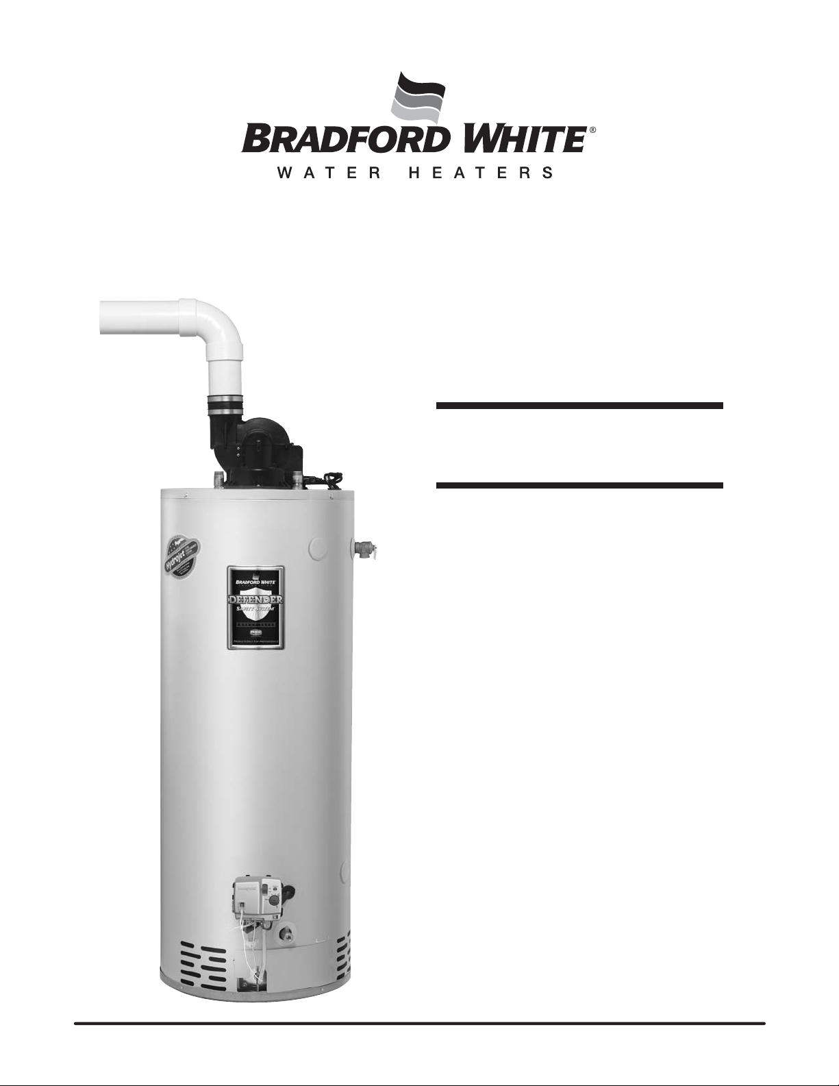
Gas Water Heaters
U TTW 75 Series
®
Page 2

Bradford White
2
U2TW Series
Gas Water Heaters
Table of Contents
Page U2TW Service Procedure
Introduction 4 - - -
How to Use This Manual 5 - - -
Tool Required for Service 5 - - -
Specifications 6 - - -
Control Timings 8 - - -
Sequence of Operation 9 - - -
Troubleshooting 12 - - -
Burner and Inner Door/Gasket Removal, Inspection
Burner Operation Inspection, Cleaning and Replacement 17 II
Pilot Testing, Cleaning and Replacement 19 III
Pressure Switch Testing and Replacement 20 IV
Blower Testing and Replacement 22 V
Blower Temperature Switch Testing and Replacement 24 VI
Gas Control Testing and Replacement 26 VII
Simulated Resistive Device Testing and Replacement 28 VIII
Resettable Thermal Switch Testing and Replacement 29 IX
Safety Circuit Voltage Trace 31 X
115VAC Circuit Trace 32 XI
Dip Tube Inspection and Replacement 33 XII
Anode Inspection and Replacement 34 XIII
Flue Baffle Inspection and Replacement 35 XIV
Glossary of Terms 36 - - -
Replacement and Reinstallation 14 I
Parts List 39 - - -
Page 2
Page 3
WARNING: If the information in these instructions is
3
not followed exactly, a fire or explosion may result
causing property damage, personal injury, or death.
Incorrect operation of this appliance may
CAUTION
create a hazard to life and property and
will nullify the warranty.
FOR YOUR SAFETY
Do not store or use gasoline or other flammable,
combustible, or corrosive vapors and liquids in the
vicinity of this or any other appliance.
WHAT TO DO IF YOU SMELL GAS
Do not try to light any appliance.
x Do not touch any electrical switch; do not use any
phone in your building.
x Immediately call your gas supplier from a neighbor's phone.
Follow the gas supplier's instructions.
x If you cannot reach your gas supplier, call the fire
department.
Installation and service must be performed by a qualified
installer, service agency or the gas supplier.
WARNING
Water heaters are heat producing appliances. To avoid
damage or injury, do not store materials against the
water heater or vent-air intake system. Use proper care
to avoid unnecessary contac
the water heater and vent-air intake components.
UNDER NO CIRCUMSTANCES MUST FLAMMABLE
MATERIALS, SUCH AS GASOLINE OR PAINT THINNER BE
USED OR STORED IN THE VICINITY OF THIS WATER
HEATER, VENT-AIR INTAKE SYSTEM OR IN ANY
LOCATION FROM WHICH FUMES COULD REACH THE
WATER HEATER OR VENT-AIR INTAKE SYSTEM.
t (especially by children) with
CAUTION
If sweat fittings are to be used DO NOT apply heat to the
nipples on top of the water heater. Sweat the tubing to
the adapter before fitting the adapter to the water
connections. It is imperative that heat is not appli
the nipples containing a plastic liner.
ed to
WARNING
Hydrogen gas can be produced in an operating water
heater that has not had water drawn from the tank for a
long period of time (generally two weeks or more).
Hydrogen gas is extr
possibility of injury under these conditions, we
recommend the hot water faucet to be open for several
minutes at the kitchen sink before you use any electrical
liance which is connected to the hot water system. If
app
hydrogen is present, there will be an unusual sound such
as air escaping through the pipes as hot water begins to
flow. Do not sm
at the time it is open.
emely flammable. To prevent the
oke or have open flame near the faucet
Do not store or use gasoline or other
flammable, combustible, or corrosive
vapors and liquids in the vicinity of this
or any other appliance.
Before proceeding, please inspect the
water heater and its components for
possible damage. DO NOT install any
water heater with damaged components.
If damage is evident then please contact
the supplie
purchased or the manufacturer listed on
the rating plate for replacement parts.
DANGER
IMPORTANT
r where the water heater was
WARNING
DO NOT ATTEMPT TO LIGHT ANY GAS APPLIANCE IF YOU
ARE NOT CERTAIN OF THE FOLLOWING:
x Liquefied petroleum gases/propane gas and natural gas
have an odorant added by the gas supplier that aids in
the detection of the gas.
x Most people recognize this odor as a “sulfur” or “rotten
egg” smell.
x Other conditions, such as “odorant fade” can cause the
odorant to diminish in intensity, or ”fade”, and not be
as readily detectable.
x If you have a diminished sense of smell, or are in any
way unsure of the presence of gas, immediately contact
your gas supplier from a neighbor's telephone.
Gas detectors are available. Contact your gas supplier, or
plumbing professional, for more information.
WARNING
FAILURE TO INSTALL AND MAINTAIN A NEW, LISTED 3/4” X
3/4” TEMPERATURE AND PRESSURE RELIEF VALVE WILL
RELEASE THE MANUFACTURER FROM ANY CLAIM THAT
MIGHT RESULT FROM EXCESSIVE TEMPERATURE AND
PRESSURES.
CAUTION
Turn off or disconnect the electrical power supply to the
water heater before servicing. Label all wires prior to
disconnection when servicing controls. Wiring errors can
cause improper and d
operation after servicing.
angerous operation. Verify proper
Page 3
Page 4

Introduction
4
The newBradford White U2TW & UTW4water heaters are designed toprovidereliable
performance with enhanced standardfeatures.Newdesign features includereliablespark to
pilot ignition system, enhanceddiagnostics, simplified
and additionalvent lengths.Inaddition, the U2TW & UTW4water heaters provideUltra Low
NOx emissions.
SparktoPilot Ignition System-employing thespark to pilot ignition systempromotes
reliableand cons
istent pilotand main burner ignitionstoprovide hot water on demand.
Integrated Immersion Thermostat/Gas Control Valve with LED -was developedfor ease
of troubleshooting by providing simple diagnostic codes to pinpointaninstallation or
component performance issu
e.
Powerful Blower - will eliminate problems with difficult venting situations.
Quieter and Cooler Blower Operation - blower noise issignificantly reducedfor both
interiorand exteriorenvironments. Cooler operation increases blower life by reducing bearing
wear and noise
.
RuggedWiring Connections - receptacletype connections promote error free wiring.
IncreasedVent Lengths - increasedventing performance isachieved while maintaining
Energy Factor &FHSR performance.
servicing, significantly quiet operation
Page 4
The U2TW & UTW4w
ater heaters use a combustion systemwhere flue gases are combined
with dilution airto reducethe flue gas temperature in the blower. The diluted flue gases are
evacuated to theexteriorthrough low temperature vent materials. The gas control ma
intains
water temperature, ignition sequenceand regulates gas flow. A safetycircuit consisting of a
pressure switch and blower temperature switch verifies proper conditionsexist forsafeand
reliable operation. If asituation outside of normaloperating parameters exi
sts, the gas control
diagnostic LED will flash a codetopositively identify anoperationalissue.
This service manualis designed tofacilitate problemdiagnosisand enhance serviceefficiency.
Please read the service manual completely before atte
mpting service on this new series of
power vent models.
Page 5

How to Use This Manual
5
It is intended for this manual to be used by qualified service personnel for the primary purpose of
troubleshooting and repair of the Bradford White U2TW Series water heaters. Understanding the
sequence of operation section of this manual will contribute greatly to troubleshooting the water
heater.
The Honeywell WV4462A Electronic Gas Control will display error codes in the event of abnormal
operation. Error codes are listed in the troubleshooting chart beginning on page 12 of this service
manual. The troubleshooting chart will also indicate the probable cause for the error code and
direct the service professional to a service procedure to properly diagnose the abnormal operation.
In some difficult to diagnose conditions, it may be necessary to isolate the heater from the vent
system to determine the problem.
Contact the Bradford White technical support group immediately if diagnosis cannot be made
using the methods described in this service manual.
Tools Required for Service
Manometer:A liquid “U” tube type or a digital type can be used. This device is used to
measure gas and/or air pressure and vacuum.
Multi-Meter:A digital type is strongly recommended. This device is used to measure
electrical values. The meter you select must have the
measure volts AC, volts DC, Amps, micro-amps and ohms.
Electronic Probes: In some cases, standard multi-meter probes will damage or simply
not be effective to obtain certain voltage and ohm reading. It will be
necessary to have special electronic “pin” type multi-meter probes.
These probes are available at
Thermometer: Used to measure water temperature. An accurate thermometer is
recommended.
Water Pressure Gauge: Used to measure water supply pressure. Also used to determine tank
pressure by adapting to the drain valve of the heater.
Various Hand Tools:Pipe wrench, channel locks, open end wrenchs (3/8",7/16",
12" crescent wrench, Allen wrench set, screw drivers (common &
Phillips), ¼" nut driver, pliers (common & needle nose), socket set, side
cutters wire cutters, wire strippers, wire crimpers, torpedo level, small
shop vac, step ladder, flashlight and 5 gallon pail.
most electronic wholesale outlets.
capability to
½"),
Page 5
Page 6
Specifications
6
Power supply Dedicated 115VAC, 60 Hz, 15A
Gas Supply Pipe Minimum 1/2" NPT (schedule 40 black iron pipe recommended)
Approved Gas Type Natural.
Gas Pressure 6.0" W.C. min. and 14.0" W.C. max.
Venting System Power vent through the wall or vertical through the roof
Approved Vent Materials PVC, CPVC or ABS
Minimum Clearance
for Servicing
Water Supply Pressure 150 PSI maximum allowable working pressure. Check local codes for supply pressure
Thermal well ECO Limit Residential 188°F (87°C), Commercial 199°F (93°C)
Residential Temperature
Set Point Range
Commercial Temperature
Set Point Range
18" from top, 24" from front, 4" sides and rear.
60°F (16°C) to 160°F (71°C) (Approximate temperatures)
80°F (27°C) to 180°F (82°C)(Approximate temperatures)
Blower Temperature Switch Normally closed, opens @ 165°F (74°C), auto reset @ 130°F (54°C).
Pressure switch
Blower
U2TW75 and UTW475S Models:
Normally open, closes on vacuum increase @-1.28, opens on vacuum decrease @-1.25
U2TW75 and UTW475S Models:
115VAC, 60Hz, 3.1 amps, 3000 RPM,68 CFM@0.4" W.C.
Page 6
Page 7
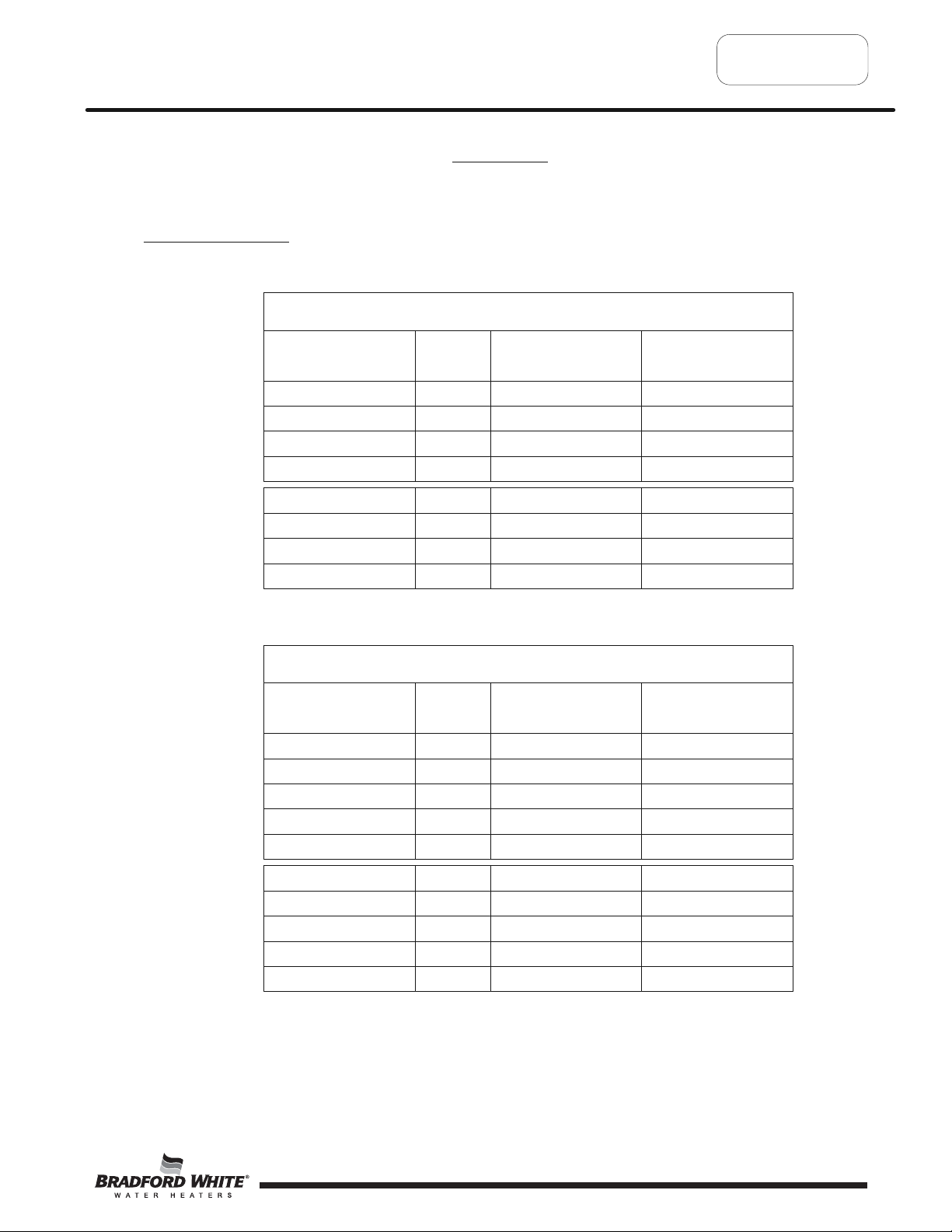
Venting Specifications:
7
Specifications
Vent Tables
3" Diameter (7.6 cm) PVC Vent Connector Lengths
Terminating
Through the Wall
# of
Elbows
1 45(13.7) 2 (.6)
Maximum
Length ft (m)
Minimum
Length ft (m)
Through the Wall 2 40(12.2) 2 (.6)
Through the Wall 3 35 (10.7) 2 (.6)
Through the Wall 4 30 (9.1) 2 (.6)
Through the Roof 0 50 (15.2) 7 (2.1)
Through the Roof 1 45(13.7) 7 (2.1)
Through the Roof 2 40(12.2) 7(2.1)
Through the Roof 3 35 (10.7) 7(2.1)
4" Diameter (10.2 cm) PVC Vent Connector Lengths
Terminating
Through the Wall
# of
Elbows
1 175 (53.3) 10 (3.1)
Maximum
Length ft (m)
Minimum
Length ft (m)
Through the Wall 2 170 (51.8) 10(3.1)
Through the Wall 3 165 (50.3) 10(3.1)
Through the Wall 4 160 (48.8) 10(3.1)
Through the Wall 5 155 (47.2) 10(3.1)
Through the Roof 0 180 (54.9) 15 (4.6)
Through the Roof 1 175 (53.3) 15(4.6)
Through the Roof 2 170 (51.8) 15(4.6)
Through the Roof 3 165 (50.3) 15(4.6)
Through the Roof 4 160(48.8) 15(4.6)
Page 7
Page 8
Specifications
8
Control Timings
Pre-purge 2 Seconds
Trial for Ignition 90 Seconds
Flame Stabilization Period 3 Seconds
Inter-purge 15 Seconds
Flame Failure Response Time 1.5 Seconds (2 second. Maximum; 1 second minimum.)
Post-purge 15 Seconds
PS Fault Delay (failed open/close) Retry after 2 Minutes
Soft Lockout Retry after 5 Minutes
ECO Limit Lockout Indefinite (cycle power to restart)
Verify Resistive Delay Retry after 2 Minutes (repeats 5 times)
Simulated Resistive Load Lockout Indefinite (cycle power to restart)
Hardware Error Lockout Indefinite (self clears if fault clears for at least 15 seconds)
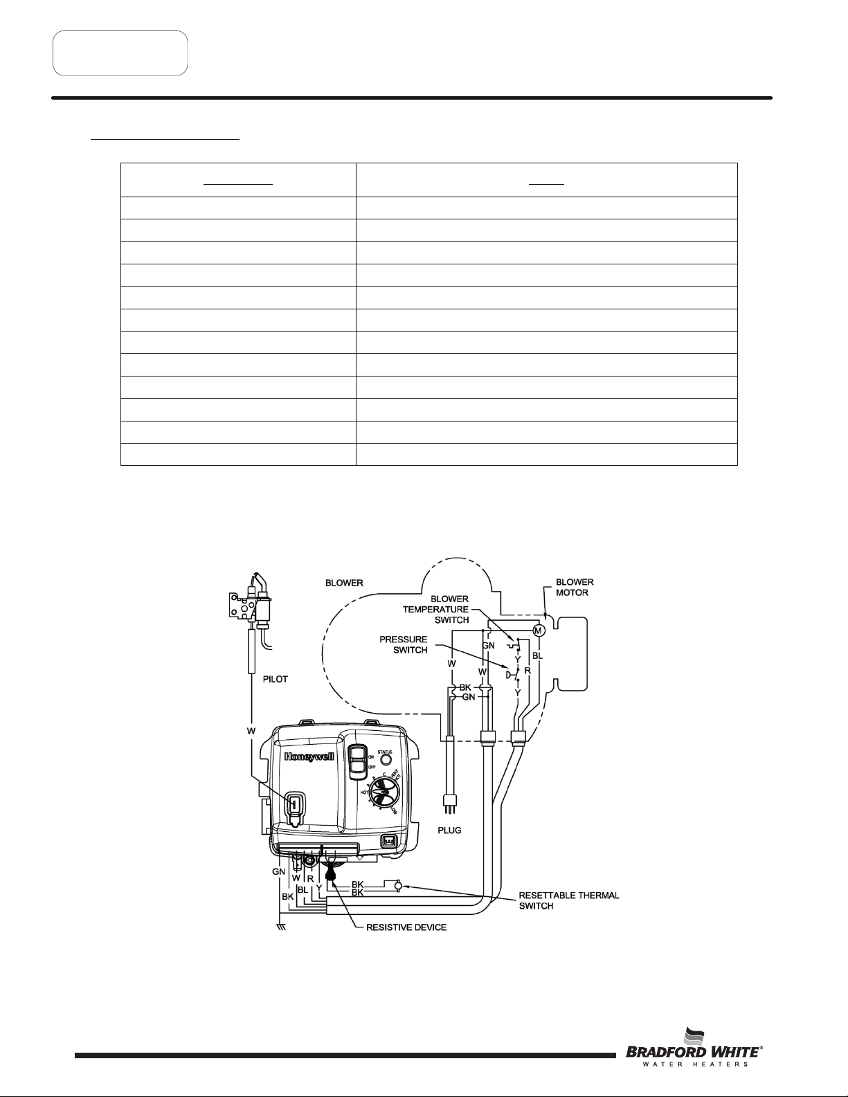
Ignition State Timing
Wiring Diagram
Page 8
Page 9

Sequence of Operation
9
Power up Sequence
1
Start Up.
Uponpower up, the control runs a safe-start check withatypical start-up delay of 1-5 seconds.
2
SimulatedResistive Load Device Check.
To assure no outputs are energized if the “Simulated Resistive device” is out of range, the control will test the
the device for proper operating range. If the device is within range the control resumes normal operationwith no
perceivable delay. If the device isoutofrange, the control LED immediately flashes 7 times with 3 second pause.
Normal Heating Sequence
1
Thermostat Calls for Heat.
Prior to energizing blower,gas control checks safetycircuittoinsure the circuit isopen. Normal switch positions
in the safetycircuit are as follows:
a) Pressure switch normally open.
b) Blower temperature switch normallyclosed.
If the safetycircuit is
closed, the control waits 4 seconds,gas control LED flashes 2 times with 3 second pause.
Gas control waits 2 minutes then, blower runs for 30 seconds. This cycle repeats until safetycircuitopens.
2
Blower Energizes.
3
Blower Pre-purge Period(2seconds)
4
Pressure Switch Proves Blower/Vent System Operation.
If the pressure switch does not close within 30 seconds, the control LED Flashes 3 times with 3 second pause.
The blower runs for 30 seconds every2minutes trying to get the pressure switchorblower temperature switchto
close. This cycle repeats as long as there isacall for heat.
5
Trial for Pilot Ignition(90 seconds).
a) The gas control lights the pilot by activating spark igniter and gas flow to pilot burner.
b) If flame is not sensedwithin 90 seconds, igniter and gas flow are deactivated, blower will post purgeand
control LED flashes 6 times with 3 second pause.
6
Main Burner Ignition
After pilot flame issensed, gas control activates main valve for main burner ignition. The gas control will ignore
flame and pressure switchsignals for 3 seconds allowing for main burner to stabilize.
Page 9
Page 10

Sequence ofOperation
10
Normal Heating Sequence (cont.)
Steady State Operation.
7
During Steady State Operation the Control Monitors:
Thermostat temperature sensor- When set point temperature issatisfied,gasvalveis shutdown and
blower will postpurge for 15 seconds. Control LED flashes a short flash onceevery 4 seconds (idle) status
code.
Pressure switch /Blower temperature switch- If either switch opens, pilot valve and main valveis shut
down. The blower continues to runsfor 30 seconds attempting to closethe circuit. The control LED Flashes
3 times with 3 second pause.
Flame Sensor- Ifflameis lost, pilot & main valve are shutdown,blower runsfor 15 seconds.
to re-light pilot 4 times.Ifunsuccessful,Blower is shutdown and control proceeds to 5 minute lockout. Control
re-attempts to light pilot starting at normal heatingsequence#2.
8
Thermostat Satisfies.
9
Burner Off.
10
Blower Post Purge (15 seconds).
Control attempts
Abnormal Operation
1.Simulated ResistiveDeviceFault:
a)Ifthe resistance is greater than 70,000 Ohms - the gascontrol immediately turns off all outputs. Control waits
and monitors resistance for 30 seconds.If theresistanceisgreater than 70,000 ohms after 30 seconds, the
gascontrol proceeds to verifyresistive delay
pause. This process is repeated 5 timesuntil the control either returns to normal operation or proceeds to flashing
7 times with a3second pause.
b) If the resistance is below 3000 ohms - The gascontrol immediately turns off all outp
8 times then once with three second pause. The error selfclears if theresistance returns to normal range for at
least 15 seconds.
for 2minutes and flashes 8 times then once with athree second
uts and proceeds to flash
2. Temperature Sensor Fault:
a) Temperature sensor detected open circuit - The gascontrol Immediately turns off all outputs and proceeds to
flash 8 times then twice with three second pause. The error selfclears if the fault clearsfor at least 15 seconds.
b) Temperature sensors not reading the sametemperature within ±5.5 °F - The gascontrol Immediately t
all outputs and proceeds to flash 8 times then three times with three second pause. The error selfclears if the fault
clearsfor at least 15 seconds.
c) Water temperature in excess of ECO (Energy Cut Out)limit - The gascontrol immediately turns off pilot &
main valve and proc
The set point knobshould beturned to the minimum temperature settingfor at least 6seconds and then turned
clockwise by at least45
Page 10
eeds to flash 4 times with 3 second pause. Blower continues to run until gascontrol is reset.
o
.
urns off
Page 11

Sequence of Operation
11
Abnormal Operation (cont.)
3. Pressure Switch/Blower Temperature Fault:
a) Pressure switch closed at start of call for heat - Thegas controlwaits four seconds then, proceeds to flash
2 times with 3 second pause.The controlwaits 2 minutes and then turns on blower for 30seconds. Theblower
turns off after 30seconds and the controlwaits for pressure switch to open. Any time the Pressure switch
theblower turns on (or stays on) and the control proceeds to wait for pressure switch to close.
b) Pressure switch or blower temperature switch failed open - Thegas control runs theblower for 30seconds
waiting for the pressure switch and/or blower temperature switch to close.If either sw
seconds,theblower turns off and the control flashes 3 times with 3 second pause.Thegas controlwaits two
minutes before turning on theblower for another 30seconds to see the circuit close.This cycle repeats aslong as
there is acall for heat or
c) Pressure switch or blower temperature switch opens during burner operation - Thegas control turns off the
pilot and main valve, runs blower for 15seconds (inter-purge) waiting for pressure switch and/or blower
temperature switch to close.If either switch fails to close, th
circuit closes again by the end of the inter-purge, the recyclecounter is incremented, if the recyclecount has
not reached itslimit (4), another trial for ignition begins. Ifthe recyclecount has been reached, thegas control
turns off theblower and flashes 6 times then 2 times with 3 second paus
repeating ignition sequence.
until the circuit closes.
e control proceeds as described in 3b above.Ifthe
e.Thegas controlwaits5minutes before
itch does not closein30
opens,
4. Trial For Ignition Fault:
a) Pressure switch opens during trial - Thegas control turns off igniter and pilot valve.Thegas control proceeds
as described in 3b above.Ifthe pressure switch closeswithin 30seconds thegas controlwill continue with trial for
ignition starting at blower pre-purge.
b) Flame Not Sensed - Thegas control energizes the s
flame is not sensed within 90seconds,the igniter turns off, thepilot valve is closed and thegas control runs the
blower through postpurge and flashes 6 times then once with 3 second pause.The controlwaits5minutes before
repeating the ignition sequence.
park igniter attempting to lightthepilot and prove flame.If
5. Flame Sensing Fault:
b) Flame lost during run - Thegas control turns off pilot and main valves,runs blower for 15seconds (inter purge).
Thegas control increments the recyclecount, if the recyclecount has not reached itslimit (4), another trial for
ignition begins. Ifthe recyclecount has been reached, thegas control turns off theblower and fla
then 3 times with 3 second pause.Thegas controlwaits5minutes before repeating the ignition sequence.
c) Flame sensed out of sequence - thegas control only looks for pilot flame when theblower is running.Ifflame is
present when thepilot valve is not open, thegas control proceeds to wait for flame loss
second pause.This continuesuntil flame islost, once theflame signal islost, the control flashes 6 times then 4
times with 3 second pause.The controlwaits5minutes before repeating the ignition sequence.
and flashes 5 times with 3
shes 6 times
Page 11
Page 12
Troubleshooting
12
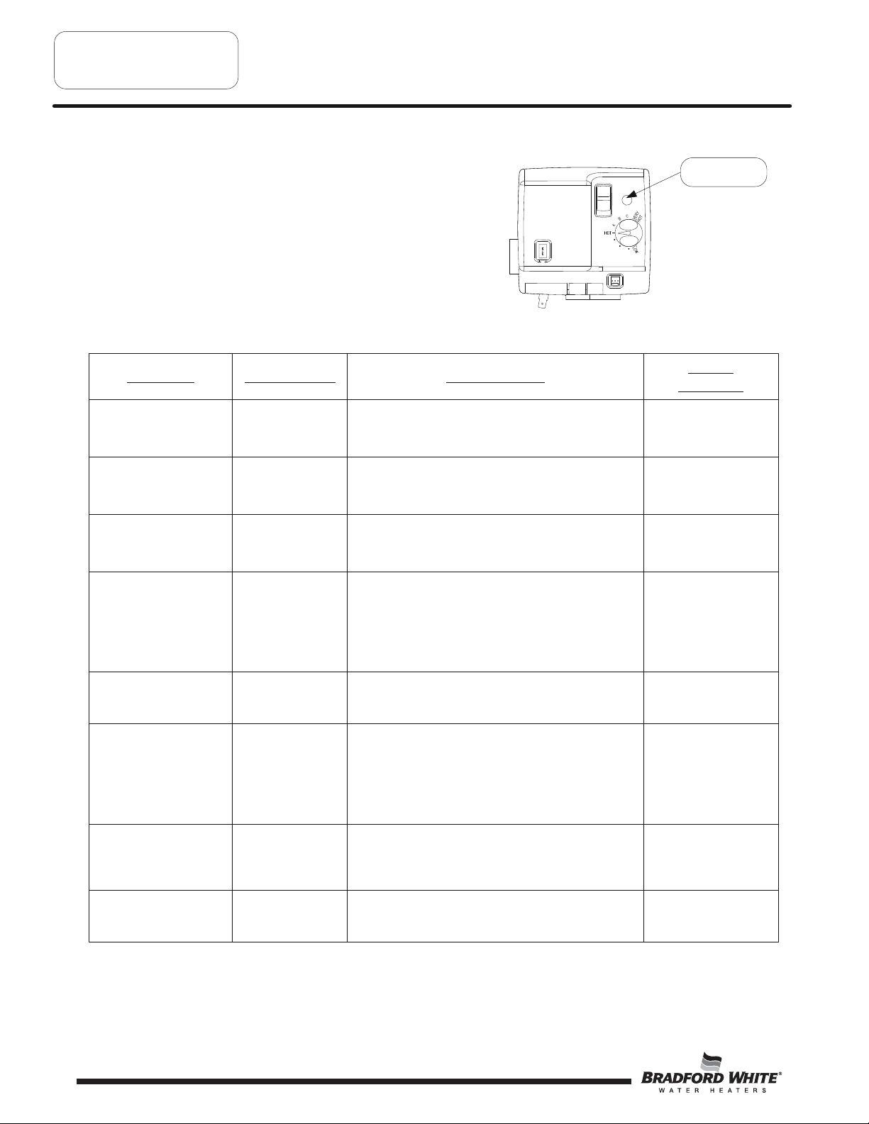
Observe green LED indicator on Electronic gas
control. Error flash codes are displayed with a
three second pause before repeating. Check
and repair the system as noted in the
troubleshooting table below.
LED Status
None, control LED not on
or flashing
Short flash, once every
four seconds
“Heartbeat”, alternates
bright/dim
Control Status
No electrical
power
Stand-by mode,
Waiting for call for
heat (no fault)
Thermostat calling
for heat (no fault).
Control power switch in “OFF” position.
Supply voltage interrupted.
Temperature demand is satisfied.
Tank temperature below set point of thermostat.
Probable Cause
Green LED
Indicator
Service
Procedure
Turn power on.
Normal operation.
Adjust thermostat to
temp level.
Normal operation.
Adjust thermostat to
temp level.
Short flash once per
second
Two flash, three second
pause
Three flash, three second
pause
Four flash, three second
pause
Five flash, three second
pause
Page 12
Weak pilot signal
on last call for heat.
Pressure switch not
working-closed
position.
Pressure switch or
blower temp.
switch not working
-open position.
Excessive tank
temperature.
System must be
reset.
Undesired-false
pilot flame present.
1. Unstable pilot.
2. Pilot tube blocked or restricted.
3. Oxidation build up on pilot electrode.
4. Wire damage to pilot assembly or bad
connection at
1. Pressure switch tubing kinked or blocked.
2. Blocked pressure tap on switch or blower.
3. Faulty pressure switch.
1. Vent blockage or improper vent configuration.
2. Pressure switch tubing kinked or blocked.
3. Faulty pressure switch.
4. Blower not spinning up to speed.
5. Blower temp or exhaust temp too high.
6. Faulty blower temperature switch.
1. Thermal well sensor out of calibration.
2. Faulty gas control.
3. Plumbing leak
1. Pilot valve stuck in open position.
gas valve.
1-4. Page 19
Page 20
1. Check vent or vent
tables
2 & 3. Page 20
4. Page 22
5 & 6 Page 23
1-2. Replace gas
control, page 26
Replace gas control,
page 26
Page 13

Troubleshooting
13
LED Status Control Status
Six-one flash, three
second pause
Six-two flash, three
second pause
Six-three flash, three
second pause
Failed to light pilot.
System auto resets.
Pressure switch or
blower temp switch
opened during
burner operation.
System auto resets.
Pilot flame
extinguished.
System auto resets.
Probable Cause
1. Unstable pilot.
2. Pilot tube blocked or restricted.
3. Oxidation build up on pilot electrode.
4. Wire damage to pilot assembly or bad
connection at
1. Vent blockage or improper vent configuration.
2. Pressure switch tubing kinked or blocked.
3. Faulty pressure switch.
4. Vent termination being affe
5. Blower not spinning up to speed.
6. Blower temp or exhaust temp too high.
7. Faulty blower temperature switch.
1. Unstable pilot.
2. Pilot tube blocked or restricted.
3. Oxidation build up on pilot electrode.
4. Wire damage to pilot assembly or bad
connection at
5. Insufficient combustion air.
6. Gas pressure is out of specification.
gas valve.
cted by wind.
gas valve.
Service
Procedure
1-4. Page 16
1. Check vent or vent
tables
2 & 3. Page 20
4. Refer to venting
section of
installation manual
5. Page 22
6 & 7. Page 23
1-4. Page 16
5. Refer to installation
manual
Six-four flash, three
second pause
Seven flash, three second
pause
Eight-one flash, three
second pause
Eight-three flash, three
second pause
Eight-four flash, three
second pause
Undesired-false
pilot flame sensed.
System auto resets.
Simulated Resistive
Device Harness out
of specification.
Simulated Resistive
Device Harness
specification check.
Thermal well
sensor damaged or
unplugged
Gas valve
electronics fault
detected
Gas valve fault
detected.
Pilot valve stuck in open position.
1. Simulated resistive device out of specification.
2. Resettable thermal switch open.
1. Simulated resistive device out of specification.
2. Resettable thermal switch open.
1. Damage to thermal well wire.
2. Thermal well sensor resistance out of range.
1. Control needs to be reset.
2. Control is wet or physically damaged.
1. Control needs to be reset.
2. Control is wet or physically damaged.
Replace gas control,
page 26
1. Page 28
2. Page 29
1. Page 28
2. Page 29
1 & 2. Replace gas
control, page 26
1. Interrupt power
supply
2. Replace gas control,
page 26
1. Interrupt power
supply
2. Replace gas control,
page 26
Page 13
Page 14

UTTW SERVICE PROCEDURE I
14
R
Burner and Inner Door/Gasket Removal,
Inspection, Replacement and Reinstallation
Inner Door Removal Procedure
Step1. Position gas control power switch to the “OFF”
position and unplug heater from wall outlet.
Step 2.Remove outer jacket burner access door.
Step3. Remove wire clip from main burner feedline.
Step 4. Inner Door Removal.
a)Disconnectthe spark igniter/flame sensor wireand the
simulated resistive device from the gas control (see photo 1).
b) Disconnect main burner feed line (¾” wrench), pilottube
(7/16" wrench) and igniter wire from gas con
c) Remove (2) ¼” hex drive screws from right side inner door
(see photo 3).
d) Remove (2) ¼” hex drive screws from flange section of
inner door (see photo 3).
e)Remove (3) 1/4" hexdrive screws from burner door
(see photos 4&5). The burner door and burner are
one-piece
.
3
trol (see photo 2).
Pilot Tube
Gas Control shown in the “OFF” position
1
Simulated Resistive
Device
Spark Igniter/
Flame Sensor
Wire
2
Main Burner
Feedline
Flange Hex
Drive Screws
Igniter Wire
Position #2
Position #3
Right Side
Hex Drive
Screws
Burner Door
Hex Drive
Screws
4
5
f) Remove burner and inner door and inspect perstep5.
Step 5. Fully inspect burner door and rightside inner door gaskets forthe following:
>Tears >Other imperfectionsthat will inhibit properseal
>Missing Material >Gasket adhesion to inner door
>Cr
acks >Materialleft on combustion chamber (around opening)
>Dirt or debris
If the gasket is not effectedbyany of theabove,gasketreplacement is notrequired. If replacement
required, proceed to Inner Door GasketReplacementProcedure.
Page 14
Position #1
is
Page 15

UTTW SERVICE PROCEDURE I
15
R
Burner and Inner Door/Gasket Removal,
Inspection, Replacement and Reinstallation
Inner Door Gasket Replacement Procedure
WARNING
If the information in these instructions is not
followed exactly, a fire or explosion may result causing
propertydamage, personal injury or death.
Step6. After inspection of inner door as notedinstep 5, completely remove gasket and adhesive residue from burner
door and rightside inner door as needed.
Step7. Use RTV sealant (re
commendedbead size 1/8") to secure the inner door gasketto the inner doorsections
(right &burner). The burner door gasket must be slicedinthe location shown on the illustration below in
derto slide the gasket overthe burner venturi. Referto illustration below for proper RTV sealant
or
application. Note the overlap configuration in the flangearea of the inner door.Ensur
the gasket faces outward. Setthe flange section first, this will help to achieve the proper overlapposition.
Re-installation of Inner Door With Gasket
e thatthe chamfer of
Step8. Clean any residualgasketresidue or other debris
from combustion chamb
ersurface before
re-installing the inner door/gasket assembly.
Step9. Place the burner door intoposition first. Tighten
the feed line nutto the gas control. Use the ¼”
hexdrive screwwithou
tthe built-in washerto
secure burner doorto the chamber at position #1.
Use the ¼” hex drive screws with the built-in
washerto secure the door at positions #2
(see photos 4&5, on page 14).
DO NOT OVER TIGHTEN SCREWS.
WARNING
Stripped fastener connections may allow
for seal breach of inner door. A seal
breach may result in a fire or explosion
causing propertydamage, personal injury
or death. Do not over tighten screws in
steps 9, 11 and 12.
If a fastener connection is stripped,
contact the manufacturer listed on the
water heater rating plate.
Page 15
Page 16

UTTW SERVICE PROCEDURE I
16
R
Burner and Inner Door/Gasket Removal,
Inspection, Replacement and Reinstallation
Position Thermopile Wire,
Pilot Tube and Igniter Wire
6
Step 10. Position thermopile wires, pilottubeand igniter wire
against burner door flange gasket
(see photo 6).
Step 11. Firmly place right side inner door flange against the burner door flange and secure with two ¼” drive
screws from step4d(see photo 7). DO NOT OVER TIGHTEN SCREWS.
Step12. Align rightside inner doorto combustion chamber and verify the fastener holes of the combustion
chamber arealignedwith the rightside inner
doorslottedopening (see photo 7). Verify sealintegrity around
combustion opening. Secure rightside inner door using 1/4” hex drive screws from step 4c.
DO NOT OVER TIGHTEN SCREWS. Verify bothburner and rightsides of the inner door are properly
position
ed and sealed against the combustion chamber.
Secure flange with ¼"
drive screws.
Verify threaded hole
alignment with slotted
openings in inner door.
7
Step 13. Reconnectspark igniter/flame sensor wireand simulated resistive device to the gas control (See photos 1&2
on page 14).
Step 14. Reconne
ctthe pilottube to the gas control and tighten.
Step 15. Replace outer jacket burner access door.
Step 16. To resume operation follow the instructions locatedonthe lighting instruction labelo
rthe lighting instructions
locatedinthe installation and operation manual.
Page 16
Page 17

UTTW SERVICE PROCEDURE II
17
R
Burner Operation Inspection,
Cleaning and Replacement
Main Burner Inspection, Cleaningand Replacement
At periodic intervals (not more than6months) a visualinspection should be made of the main burner for proper operation
and toinsure no debris is accumulating.
Main burnershould lightsmoot
hly from pilot and burnwith a blue flame with a minimum of yellow tips.After
approximately 5 minutes of operation the burnerscreen will become radiant and the flame will soften and turnorange.If
the burn
erscreendoes not become radiant after 5 minutes of operation it must be cleaned(see burner cleaning procedure
below).
Main burner must be free from any debris accumulation that may a
ffect burner operation (see burner cleaning procedure
below).
DANGER
Under no circumstances shall flammable materials be used or stored in the vicinity ofthe water heater. If
flammable vapors are present, a fire or explosion may result causingproperty damage,personal injury or
death.
WARNING
Inner door andburner components maybe HOT when performing this operation. Take
necessary precaution to prevent personal injury.
Burner Cleaning
Step1. Remove burner and inner door assembly per SERVICE PROCEDURE I, steps 3 through 4.
Step 2.Remove manifold cover from burner inner door by removing (2) ¼” hex drive screws and then sliding
manifold coverto the right. Useastiff brush, compressed air and/o
build up from the manifold mount.
Step3. Remove manifold brackets from burner by removing (4) ¼” hex drive screws.
rshop vacuum to removeany debris
¼” Hex Drive Manifold
Cover Screws
Manifold Cover
¼” Hex Drive Manifold
Bracket Screws
Page 17
Page 18

UTTW SERVICE PROCEDURE II
18
R
Burner Operation Inspection,
Cleaning and Replacement
Burner Cleaning (Continued)
Step4. Thoroughly inspect burnerscreen and burner venturis and removeany loose debris accumulation. Inspect
burnerscreenfor any openings largerthan the normal screenopenings
Step5. Use compressed air and/or a vacuum to removeany scale or other debris accumulation from the burnerscreen
and venturis.
.
Burner Screen
Burner Venturis
Manifold Brackets
Step6. Disconnect (unscrew) manifold brackets from main
burner orifices.
Main Burner Orifices
Step7. Remove main burner orifice from feed line (1/2"
wrench). Inspect and cleanifnecessary
Step8. Remove pilot assembly, ref
erto SERVICE PROCEDURE III for cleaning and inspection.
Step9. Reassemble burner.
Step 10. Reinstall burner and inner door per SERVICE PROCEDURE I, steps 5 through 16.
Step 11. To resume operation, follow the instructions locatedonthe ligh
instructions locatedinthe installation and operation manual.
Page 18
ting instruction labelorthe lighting
Page 19

UTTW SERVICE PROCEDURE III
19
R
Pilot testing, Cleaning and Replacement
Pilot Assembly Inspection, Testing
and Replacement
Step1. Position gas control power switch to the “OFF”
position and unplug water heater from wall outlet.
Step 2.Remove outer jacket door.
Step3. Remove burner and rightside of inner door
per SERVICE PROCEDURE I, steps
3 and 4.
Step4. Remove burner assembly from combustion chamber.
Step5. Remove pilot/electrodeassembly from burner (¼" drive tool)
Step6. Inspect pilot for kinks or cracks in the pilottube.
If found, the pilot must be replaced.
Step7. Inspec
t pilot orifice:
a)Remove 7/16" nut from bottom of pilot assembly.
b) Remove pilottubeand pilot orifice.
Gas Control shown in the “OFF” position
Pilot
Location
c) inspect pilot orifice for blockage,must be cleanedorreplaced.
¼” Hex Drive
Pilot Screw
Pilot Orifice
Pilot Tube
7/16" Pilot
Assembly Nut
Step8. Install pilot/electrodeassembly toburner, s
ecure with screwfrom step5.
Step9. Install burner and inner door per SERVICE PROCEDURE I, steps 5 through 16.
Step 10. To resume operation follow the instructions locatedonthe lighting instruction labelorthe lighting instr
locatedinthe installation and operation manual.
uctions
Page 19
Page 20

UTTW SERVICE PROCEDURE IV
20
R
Pressure Switch Testing and
Replacement
Pressure Switch Testing
WARNING
115 volt potential exposure. Use caution
Step1. Position gas control powerswitch to
making voltage checks to avoid personal injury.
the “OFF” position.
Step 2.Remove the three screws (Phillipsscrewdriver)from control access cover on blower assembly and
remove cover (see photos 1 and 2).
Step3. Care
With steps 1,2 & 3 complete,
disconnect wire leads from
pressure switch.
Use a multi-meter set to the
ohms setting. With blower off,
check across pressure
switch terminals.
Are switch contacts open?
(no electrical continuity)
fully remove pressure switch from blower housing (see photo 3).
1
Control
Access Cover
Screws
Pressure switch
wire leads
N
Y
Check tubing and pressure tap
on switch for blockage.
Is there blockage?
Y
N
3
Pressure Switch
Slide pressure switch in direction of
arrow while tilting slightly away
from blower housing.
Replace switch
(see page 21)
2
Position gas valve power
switch to the “ON” position
and adjust thermostat
to call for heat,
this will start the blower.
Check with multi-meter, do
pressure switch contacts close
with blower running?
Switch contacts are OK.
See safety circuit trace
(page 31)
Page 20
Clear blockage
Y
Check tubing and
N
Y
pressure tap on
switch for blockage.
Is there blockage?
N
Y
Is vent
system
blocked
Is vent system length
N
within vent table
specifications
listed on page 7
N
Reconfigure vent
system to be
compliant with
vent tables.
Y
Y
See blower testing
(page 22)
Is blower OK?
N
Correct blower
problem.
Page 21

UTTW SERVICE PROCEDURE IV
21
R
Pressure Switch Testing and
Replacement
Pressure Switch Replacement
WARNING
115 volt potential exposure. Use caution
to avoid personal injury.
Step1. Position gas control powerswitch to
the “OFF” position.
Step 2.Remove the three screws (Phillipsscrewdriver)from control access cover on blower assembly and
remove cover (
see photos 4 and 5).
5
4
Control Access
Cover Screws
Pressure Switch
6
Step3. Carefully remove pressure
switch from blower
housing (see photo 6).
Slide pressure switch in direction of
arrow while tilting slightly away
from blower housing.
Step4. Disconnecttubing from
7
pressure switch
(see photo 7).
Step5. Disconnect yellow wires
from pressure switch
(see photo 8).
Step6. Reconnect wires from step5tonewpressure switch.
Step7. Reconnecttubing tonewpressure switch.
Step8. Carefully position pressure switch into blower housing.
Step9. Position gas control power switch to “ON” position and verify proper heater operation.
Step 10. Replace
control access cover from step 2.
8
Page 21
Page 22

UTTW SERVICE PROCEDURE V
22
R
Blower Testing and Replacement
Blower Testing
115 volt potential exposure. Use caution when
making voltage checks to avoid personal injury.
Step1. Position gas control powerswitch
to “ON” position and adjust control to call for heat.
Step 2.Remove the three screws (Phillips Screwdriver)
from control access cover on blower assembly and
remove cover (see photos 9 and 10).
Does blower energize Within 2
minutes?
N
11 12
Does blower energize after 2
minutes, run for 30 seconds
and shut down?
N
pressure switch
Y
tubing from blower
(see photo 11).
Pressure tap
Pressure switch
See pressure switch
Y
Disconnect
tubing
testing
Page 20.
manometer to
pressure tap of
(see photo 11).
Determine voltage
problem and correct.
Connect
blower
14 15
Disconnect vent
system from top of
blower and remove
(see photo 13).
With blower running, and exhaust
adapter removed from top of blower,
is there a negative pressure of -2.15"
N
WARNING
9
Control
Access
Cover
Screws
vent adapter
to -2.30" W.C.?
N
Is there 115vac across blue
and green wires
(see photo 16)?
10
Remove exhaust
adapter
13
Y
Blower OK
Y
Replace blower
Page 22
Disconnect cord set
shown in photo 12. Is
there 115VAC across
terminals shown in photo
14?
N
Is there 115 VAC at
wall outlet?
Y
Check power cord
for damage.
N
Replace blower
Y
N
Y
Is there 115VAC across
terminals shown in
photo 15?
Incorrect supply
voltage polarity
Determine
power source
problem and
correct.
Repair or replace
power cord
Y
N
Replace
cord set
Reconnect cord set shown
in photo 12, is there
115VAC between blue wire
and green ground wire
(see photo 16).
N
Does cord set
N
have electrical
continuity?
Y
Replace gas
control
Y
Replace blower
Green ground
wire
Shown with pressure
switch removed.
16
Blue wire
Page 23

Blower Removal
23
Step1. Position gas control power switch to the “OFF”
position and unplug heater from wall outlet.
Step 2.Disconnect ventsystemfrom exhaust adapter
on top of blower.
UTTW SERVICE PROCEDURE V
R
Blower Testing and Replacement
Gas Control shown in the “OFF” position
Step3. Removeexhaust adapter from blower (bla
screwdriver) and retain for use on new blower.
de
Remove exhaust adapter
and retain for use on
new blower.
Step4. Unplug cord sets from blower.
Step5. Remove the three blower mounting screws
(¼" nut driver).
Step6. Remove blower withgasket from w
ater heater.
Blower Installation
Step7. Clean any debris from jacket headofwater heater.
Step8. Set new blower withgasket in place using locating pins on
blower flange to line up with location holes in jacket head.
Be sure nottodam
Step9. Secure blower in place using mounting screws from step6.
Step 10. Re-install exhaust adapter from step4.
Step 11. Reconnect ventsystem to
exhaust adapter.
age gasket.
Locating Pins
on blower flange
Blower Mounting
Screws
Blower
Cord Sets
Step12.Reconnect cord sets from step5.
Pin location holes in
jacket head
Step 13. Plug blower power cordintowall outlet.
Step 14. Position gas control power switch to the “ON” position.
Step 15. Verify proper blower operation.
Page 23
Page 24

UTTW SERVICE PROCEDURE VI
24
R
Blower Temperature Switch Testing
and Replacement
Blower Temperature Switch
Testing.
Step1. Position gas control powerswitch
to the “OFF” position.
Step 2.Remove the three screws (Phillips
screwdriver)from control access
cover on blower and remove cover
(see photos 17 and 18).
Step 3. Locate blowertemper
(see photo 19).
Switch Setting
Opens on rise @ approximately165°F
Auto resets on fall @ approximately 130°F
Cool switch to
below 130°F
ature switch
WARNING
115 volt potential exposure. Use caution
to avoid personal injury.
Gas Control shown in the “OFF” position
17
Control Access
Cover Screws
19
Blower temperature
switch location
18
Disconnect wire leads to
switch. Using a multi-meter
set to the ohms setting, is
there continuity between the
switch terminals?
Y
Reconnect wire leads and
observe heater operation. Do
exhaust gas temperatures rise
to or above 165°F?
N
Do switch contacts
open?
N
Switch OK
Page 24
Y
N
Y
Replace switch
(see page 25).
Replace switch
(see page 25).
N
Do switch contacts
open?
Y
temperature is too
Air mixing inlet
Exhaust
hot.
Common causes for
high exhaust temperature
1. Vent length is below minimum allowable.
2. Vent diameter not to specification.
3. Restricted dilution air inlet.
4. Missing or deteriorated flue baffle.
5. Gas pressure is out of specification.
Page 25

UTTW SERVICE PROCEDURE VI
25
R
Blower Temperature Switch Testing
and Replacement
Blower Temperature Switch
Replacement.
Step1. Position gas control power switch to the “OFF” position
and unplug water heater from wall outlet.
Step 2.Remove the three screws (Phillipsscrewdriver)from the
control access cover on blower and remove cover
(see photo 20 and 21).
20
Control Access
Cover Screws
WARNING
115 volt potential exposure. Use caution
to avoid personal injury.
Gas Control shown in the “OFF” position
21
Step 3. Locate blowertemperature switch (see photo 17)
Step4. Disconnectred and yellow wire leads from switch.
Step5. With an appropriate tool such asside cutters, snip the
retaining lug from t
he blower housing to allow removalof
temperature switch (see photo 18).
Step6. Remove switch from blower housing.
Step7. Install new switch. Be sure switch is properly seatedin
mounting area.
Step8. Reconn
ectred and yellows wirestonew switch. Wires are
interchangeable with eitherterminal.
Step9. Position gas control power switch to the “ON” position
and verify proper heater operation.
Step 10. Replace control access cover from st
ep 2.
22
23
Blower temperature
switch location
Snip retaining lug
from blower housing
Page 25
Page 26

UTTW SERVICE PROCEDURE VII
26
R
Gas Control Testing and Replacement
Gas Control Replacement
Step1. Rotate knob of the gas control
to the “OFF” position.
Step 2. Turn off gassupply towater heater.
Step3.Disconnect gassupply line from gas control.
Step4.Turn off watersupply and drain water heater completely.
ep5.Remove the wire clip from the feedline.
St
Gas Control shown in the “OFF” position
Step6.Disconnect main burner feedline, pilottube,white thermopile wireand igniter wire from gas control and bend
the main burner feedlineand pilottube out of the
way. Alsodisconnectthe redwire leading from the thermopile
from the redwire leading from the gas control.
Step7. Remove the gas control from the water heater by rotating counter-clockwise.I
t maybe necessary tousealength
of ½” NPT pipe threaded into the inlet of the gas control.
Pilot tube
Igniter wire
White thermopile
Main burner
feedline
wire
Red Wire Leads
Step8.Install newgas control into the water heater.
a)Install gas control intowater heater by rotating clockwise.DONOT useawrench on the gas contr
body or damage to the gas control may occur.Ifnecessary, use a length of ½” NPT pipe threaded into
gas inlet of gas control.
b) Position the main burner feedlineand pilottube back to the gas control and attach to the gas control.
Connec
the gas control to the resettable thermal switch and connectthe redwire from the
tthe igniter wireand the white thermopile wire to the gas control. Connectthe redwire from
thermopile to the
resettable thermal switch.
c) Gatherthe igniter wire, white thermopile wireand red thermopile wire nearthe side of the feedline.
Use the clip that wasr
emovedinStep5to secure the wiresto the feedline.
d) Connect gassupply to inlet of gas control.
Step9.Resume the watersupply to the water heater.Be sure thatthe tank is full before
operation isresumed.
Step 10. Check the main burner feedlineand pilot feedline for gas leaks.
Step 10. To resume operation follow the instructions locatedonthe lighting instruction labelorthe lighting
uctions locatedinthe installation and operation manual.
instr
Page 26
ol
Page 27

UTTW SERVICE PROCEDURE VII
27
R
Gas Control Testing and Replacement
ManifoldPressure Testing (this procedure presumes a maximum line pressure of 14.0"
w.c.)
Gas Control shown in the “OFF” position
Step1. Position gas control power switch to the “OFF” position.
Step 2.Remove pressure tap plug (3/16" hexwrench) and install
1/8" NPT pipe, coupling, & pressure tap.
Step 3. Connect manometertopressure tap.
Step 4. Follow instructions locatedonthe lighting
instructions la
burner and observe manometerreading.
Step5. Proper operating range for naturalgas is: 5.0" ±0.5" w.c.
bel and proceed to lightthe main
Step6. Ifpressure is within the range specifiedinth
e previous
step, position gas control power switch to the “OFF”
position, remove manometer and pressure tap, and
replace pressure tap plug. Check for gas leaks priorto
placing water heater back intooperation by following
the instructions
locatedonthe lighting instruction labelor
the lighting instructions locatedinthe installation and
operation manual.
Step7. Ifgas pressure is outside the specification noted above,
Pressure Tap
Plug
refer to “Gas Control Testing and Replacement” to replace
Gas Control or v
alve body.
Pressure Tap
Shown Installed
ECO (Energy Cut Out) Testing
TheHoneywell Gas Control is designedwith an ECO device that will reset.
To resetthe Gas Control after an error code (4), rotate the set-point knob to the minimum temperature sett
6 seconds and then rotate the set-point knob clockwise by at least 45o. This will resetthe gas control and return the water
heatertonormaloperation.
ing for at least
Page 27
Page 28

UTTW SERVICE PROCEDURE VIII
28
R
Simulated Resistive Device Testing
Simulated Resistive Device Testing
Step1. Position powerswitch on gas control to the
“OFF” position.
Step 2.Disconnectsimulated resistive device from
gas control.
Step3. Using a multi-metersetto the ohmssetting
check resistance of simul
device.Resistance must be within 25,000
ohms and 45,000 ohms.Ifoutside of this
range replace the simulated resistive device.
If there is no continuity test the resettabl
thermal switch by following SERVICE
PROCEDURE IX. If the resettable thermal
switch is closed replace the simulated
resistive device
ated resistive
e
Simulated
Resistive device
Page 28
Multi-meter set to
ohms setting
Electronic
“pin type”
Meter Probes
Resettable Thermal
Switch
Simulated
Resistive device
Page 29

Resettable Thermal Switch Continuity Testing
29
Step1. Remove outer jacket door.
Step 2.Disconnectredwire leads from resettable thermal switch.
UTTW SERVICE PROCEDURE IX
R
Resettable Thermal Switch Testing
and Replacement
Red Wire Leads
Step3. Using a multimeter capable of measuring con
tinuity(Ohms),
place one probe of meter on one of the brass connection tabs of
the resettable thermal switch, and the remaining probe on the
other connection tab.
Step4. Ifcontinuityi
s indicated, the switch is closed, allowing currenttopass.
Step5. Ifcontinuityis not indicated, the switch is open, possibly due to anover heating condition. The switch is
designed toopen at predetermined
temperatures.Anopen switch canbe reset by depressing the red colored
button located atthe center of the switch. The overheating condition must be determinedpriortoputting the
ter heater back in service.
wa
PROBABLE CAUSE FOR RESETTABLE THERMALSWITCH ACTIVATION
PROBABLE CAUSE CORRECTIVE ACTION
1. Inspect burner per SERVICE PROCEDURE II
Burner Failure
2. Replace burner per SERVICE PROCEDURE II
Weak switch or switch
out of calibration.
1. Replace resettable thermal switch
Page 29
Page 30

UTTW SERVICE PROCEDURE IX
30
R
Resettable Thermal Switch Testing
and Replacement
Resettable Thermal Switch Replacement
Step1. Position gas control powerswitch to
the “OFF” position.
Step 2.Remove outer jacket door.
Step3. Disconnectredwire leads from resettable thermal switch.
Step4. Remove (2) ¼” hex drive screws from the manifold
cover and slid t
assembly.
Step6. Remove resettable thermal switch from manifold
cover (Phillipsscrewdriver).
o the rightto remove from burner
Phillips Screws
Gas Control shown in the “OFF” Position
¼” Hex Drive Manifold
Cover Screws
Red Wire Leads
Manifold Cover
Step7. Place new resettable thermal switch in place.Be
sure contactsurface of resettable thermal switch and
manifold cover are free of any debris.Secure resettable thermal switch intoplace using screws from step6.
DO NO
T OVERTIGHTEN SCREWS.
Step8. Place manifold cover back in position and secure using the screws from step4.
Step9. Reconnect wire leads from gas control and thermopile to resettable th
Note: Wire termination is interchangeable with eitherresettable thermal switch connection.
Step 10. Replace outer jacket door.
Step 11. To resume oper
ation follow the instructions locatedonthe lighting instructions labelorthe lighting
instructions locatedinthe installation and operation manual.
Page 30
ermal switch.
Page 31

Safety Circuit Voltage Trace
31
U TTW SERVICE PROCEDURE X
R
Safety Circuit Voltage Trace
WARNING
115 volt potential exposure. Use caution
making voltage checks to avoid personal injury.
NOTE: This procedureassumes a cool tank.
Step1. Remove three screws (Phillips
Screwdriver)from control
access cover on blower and
remove cover (see photo 24
and 25).
Position gas control switch to the “ON”
position and adjust thermostat dial to call
for heat, Is there 10 to 13 VAC between red
wire leading to blower temperature switch
and green ground wire?
Blower must be running
voltage check
(see photo 26).
Is there 10 to 13 VAC between yellow wire
leading from pressure switch and green
ground wire
(see photo 26)?
during this
Y
Y
N
N
Is LED on gas valve flashing the
“heartbeat” code (alternating
bright/dim)
N
Verify 115VAC to gas
control (see page 32).
Y
temperature switch
24
Control Access
Cover Screws
No voltage from gas control,
call for technical support.
Is there continuity
through blower
(see page 24)?
N
25
Y
Check for loose or
broken wire connection
at switch terminals.
Do you hear or can you see
the igniter sparking?
Y
Safety circuit
voltage is OK.
If burner does not light,
observe LED flash code on
gas valve and refer to
troubleshooting section on
page 12.
Determine cause of blower
Correct igniter/
sensor problem.
N
Check igniter/sensor
(see page 19).
is igniter/sensor OK?
26
temperature switch activation
and correct.
Faulty cord set or
Y
gas control.
Green ground wire
Red wire leading to
blower temp. switch
Yellow wire
leading from
pressure switch
Page 31
Page 32

U TTW SERVICE PROCEDURE XI
32
R
115 VAC Trace
115 VAC Circuit Trace
115 volt potential exposure. Use caution
WARNING
making voltage checks to avoid personal injury.
Step1. Verify 115VAC and proper polarity at wall outlet.
Step 2. With unit plugged in and control power switch in the “ON” position verify LED status.
LED status
None, Control LED not
on or flashing.
Disconnect cord set as
shown in photo 27.
Using a volt meter set to
volts AC, is there 115VAC
across terminals shown
in photo 28?
Y
Is there 115VAC across
terminals shown in
photo 29?
N
Incorrect supply
voltage polarity
N
Y
LED status
Short flash, once every
four seconds.
Waiting for
call for heat.
Reconnect cord set
shown in photo 27.
Disconnect wire harness
from gas control
(see photo 30).
LED status
“Heartbeat”, alternates
bright/dim.
Thermostat calling
for heat
27
Check for damage to AC
supply power cord.
N
Replace Blower
28
Y
Wire harness
LED status
Various flashing error
codes.
Verify error code as
listed on page 12
Repair damage
29
30
Locate black & white wires at connector, It
may be necessary to pull back wire sheath
to identify wire colors
(see photo 31).
Is there 115VAC across
black & white wires as
shown in photo 31?
N
Call for technical
support.
Page 32
31
Wire sheath pulled back to
identify wire colors
Y
Replace gas
control.
Check for 115VAC between black & white wires.
-NOTE-
Electronic meter probes required. Use care not to
damage connector during this check.
Page 33

U TTW SERVICE PROCEDURE XII
33
R
Dip Tube
Inspection and replacement
Dip Tube Inspection and Replacement
WARNING
Water Heater components and stored water maybe HOT when performing the following
steps in this procedure. Take necessary precaution to prevent personal injury.
Gas Control shown in the “OFF” Position
Step1. Position gas control power switch to the “OFF”
position and unplug water heater from wall outlet.
Step 2. Turn off cold watersupply towater heater. Connect hose todrain valve of water heater and route to an
opendrain. Open a nearby hot water faucettovent heater for draining. Opendrain valve of water
heater and allow heatertodrain to a point below the inlet connection nipple.
Step3. Disconnect inle
t nipple from plumbing system.
Step4 With an appropriate tool such as a pipe wrench, remove inlet nipple/dip tube from the water heater.
Use caution nottodamage pipe threads.
Step5. Vi
sually inspect inlet nipple/dip tube. Inlet nipple/dip tube should be free of cracks and any blockage.
Hydro-jetslots should be open and free of any blockage.
Any damage such as cracks, restriction due todeformat
ion or unintentionalholes are not field
repairableand the inlet nipple/dip tube must be replaced.
Step6. Upon completion of inspection orsubsequentreplacement, reinstall inlet nipple/dip tube in
towater
heater. Connect nipple to plumbing system, resume watersupply and refill withwater.
Step7. To resume operation follow the instructions locatedonthe lighting instruction labelorthe lighting
tions locatedinthe installation and operation manual.
instruc
Page 33
Page 34

U TTW SERVICE PROCEDURE XIII
34
R
Anode
Inspection and replacement
Anode Inspection and Replacement
Water Heater components and stored water maybe HOT when performing the following
steps in this procedure. Take necessary precaution to prevent personal injury.
Step1. Position gas control power switch to the “OFF”
position and unplug water heater from wall outlet.
WARNING
Gas Control shown in the “OFF” Position
Step 2. Turn off cold watersupply towater heater. Connect hose todrain valve of water heater and route to an
endrain. Open a nearby hot water faucettovent water heater for draining. Opendrain valve of
op
water heater and allow water heatertodrain to a point below the outlet connection nipple
.
Step3. Disconnect outlet nipple from plumbing system.
Step4 With an appropriate tool such as a pipe wrench, remove outlet nipple/anode from the water heater. Use
caution nottodam
age pipe threads.
Step5. Visually inspect outlet nipple/anode.Outlet nipple/anode should show signs of depletion, this is
normal. If depletion is ½ofthe original anode diameter (approximately ¾” diameter), repl
acement is
recommended. If any of the steelcore of theanode is exposed, replacement isrecommended.
Step6. Upon completion of inspection orsubsequentreplacement, reinstall outlet nippl
e/anode intowater
heater. Connect nipple to plumbing system, resume watersupply and refill withwater.
Step7. To resume operation, follow the instructions locatedonthe lighting instruction labelorthe
lighting
instructions locatedinthe installation and operation manual.
Page 34
Page 35

U TTW SERVICE PROCEDURE XIV
35
R
Flue Baffle
Inspection and replacement
Remove blower to gain access to
Disconnect vent system
from exhaust adapter.
flue baffle
Step1. Position gas control power switch to the “OFF” position
and unplug water heater from wall outlet.
Step 2.Disconnect ventsystemfrom exhaust adapter on top of
blower.
Step3. Unplug cord sets from blower.(see photo 33).
p4. Remove the three blower mounting screws
Ste
(¼" nut driver)(see photo 33).
Step5. Remove blower withgasket from water heater.
Step6. Remove flue baffle from Heater (see photo 34).
Step7. Inspec
Step8. Reinstall baffle into flue tube.Be sure baffle
t baffle for deterioration, missing restrictors.
Clean any scale or debris build up. Replace withnew
baffleas necessary.
ertab are insertedintonotch location atthe
hang
top of the flue tube (see photos 35 & 36).
33
Blower
Cord Sets
34
Blower Mounting
Screws
Flue Baffle
Step9 Check Burnertoinsure no scale has accumulatedduring
this operation. See burner cleaning procedure on pag
e 14.
Step 10. Reinstall blower on water heater. Connect vent
system and cordssetto blower. Plug water heater
intowall outlet.
Step 11. To resume operation follow the lighting instruction
locatedonthe
lighting instruction labelorthe lighting
instruction locatedinthe installation and operation
manual.
35
Flue tube
notch
36
Baffle shown
installed in flue
tube notch.
Page 35
Page 36

Glossary ofTerms
36
BTU British Thermal Units
GPM Gallons per Minute
Hz Hertz
KWh Kilowatt hour
LED Light Emitting Diode
NPT National Pipe Thread
Ohms Ohms (resistance)
PSI Pounds per Square Inch
RPM Revolutions per Minute
ECO Energy Cut Out
VAC Volts Alternating Current
W.C. Inches of Water Column
°C Degrees Centigrade
°FDegrees Fahrenheit
NOTES
Page 36
Page 37

NOTES
3
37
Page
Page 38

NOTES
38
Page 38
Page 39

Parts List
39
1.Flue Baffle
2.Inlet Dip Tube
3. Inner Door Gasket Kit
4. Hot Water Outlet Anode
5. Heat Trap Inlet
6. Heat Trap Outlet
7. Blower Assembly
8. T&P Valve
9. Outer Door
10. Gas C
11. Gas Control Wire Harness
12. Brass Drain Valve
ontrol
13. Ultra Low NOx Burner
14. Right Side Inner Door Assembly
15. Pilot Assembly
16. ¼” Manifold Mount Hex Head Screw
17. Manifold Mount
18. Main Burner Orifi
19.Main Burner Feedline
20. Resettable Thermal Switch
21.ManifoldCover
22. ¼” Manifold Cover Hex Head Screw
23. Burner Door
24. Main Burner Assembly
ce
Page 39
Page 40

 Loading...