

Page 1
INTEGRATED MIXING DEVICE (IMD)
INSTALLATION AND OPERATING INSTRUCTION MANUAL
For your family’s comfort, safety and convenience, it is recommended this IMD be
installed and serviced by a plumbing professional.
This manual will explain in detail the installation and maintenance of the integrated mixing device.
We require that you carefully read this manual and refer to it if questions arise.
PRE-INSTALLATION
The following steps should be taken to ensure proper conditions for operation:
Note all site parameters (pressure, temperature, etc.) and check against the integrated mixing
device (IMD) specifications listed in Table 1. All specifications must be met prior to installing the
IMD.
This IMD MUST NOT be subjected to heat during installation as this may damage the internal
parts.
CAUTION
If sweat fittings are to be used, DO NOT apply heat to the fittings on top of the
water heater. Sweat the tubing to the adapter before fitting the adapter to the
water connections. It is necessary that heat is not applied to the fittings to ensure
appropriate operation.
The valve MUST NOT be allowed to freeze. If the IMD is installed in a potentially freezing
situation, suitable insulation must be fitted to prevent damage.
DO NOT use excess thread sealant (in liquid, tape or other form) as this may cause the IMD to
fail. The installer must ensure that thread sealant does not get into the internal parts.
In order to install this IMD on a unit with a blower mounted on top, it is necessary to remove the
blower prior to installation and replace the blower after installation of this IMD.
If the water heater is gas-fired, the IMD must be installed before the draft hood.
This manual is meant to be used in conjunction with the installation and operation manual
(owners manual) for the water heater.
Toxic chemicals, such as used for boiler treatment, shall not be introduced into IMD used for
space heating. This IMD may never be connected to any existing heating system or
component(s) previously used with a non-potable water heating system.
Leave a copy of this instruction manual with the water heater for future reference.
Recommend to the user that the IMD be checked annually to ensure its continued function.
Page 1 238-47870-00C 08/09
Page 2
INTEGRATED MIXING DEVICE - IMD SPECIFICATIONS
Table 1
Mixed water supply temperature range
100 - 145°F (38 - 63°C)
Water heater outlet temperature range 100 - 180°F (38 - 82°C)
Cold water inlet temperature range 33 - 80°F (1 - 27°C)
Device temperature stability (nominal)
Temperature differential
(between hot supply and outlet temperature)
± 3°F (± 1.7°C) at 3 - 5 gpm (see note 1)
± 5°F (± 3.0°C) at 5 - 40 gpm (see note 1)
27°F (15°C) (see note 2)
Hydrostatic pressure 150 psi (1034 kPa) maximum
Permitted supply pressure variation
Flow rate (min)
Flow rate (max)
± 10% (see note 3)
0.25 gpm (0.9 L/m)
19.2 gpm (72.0 L/m)
2.8 (mixed temp. of 95°F)
Cv
1.8 (mixed temp. of 120°F)
1.3 (mixed temp. of 140°F)
Notes:
1. As tested in accordance with ASSE 1017.
2. This is the minimum difference required between the mixed water supply temperature and the
water heater outlet temperature to enable the IMD to function correctly and ensure shut-off of
outlet flow in the event of cold supply failure.
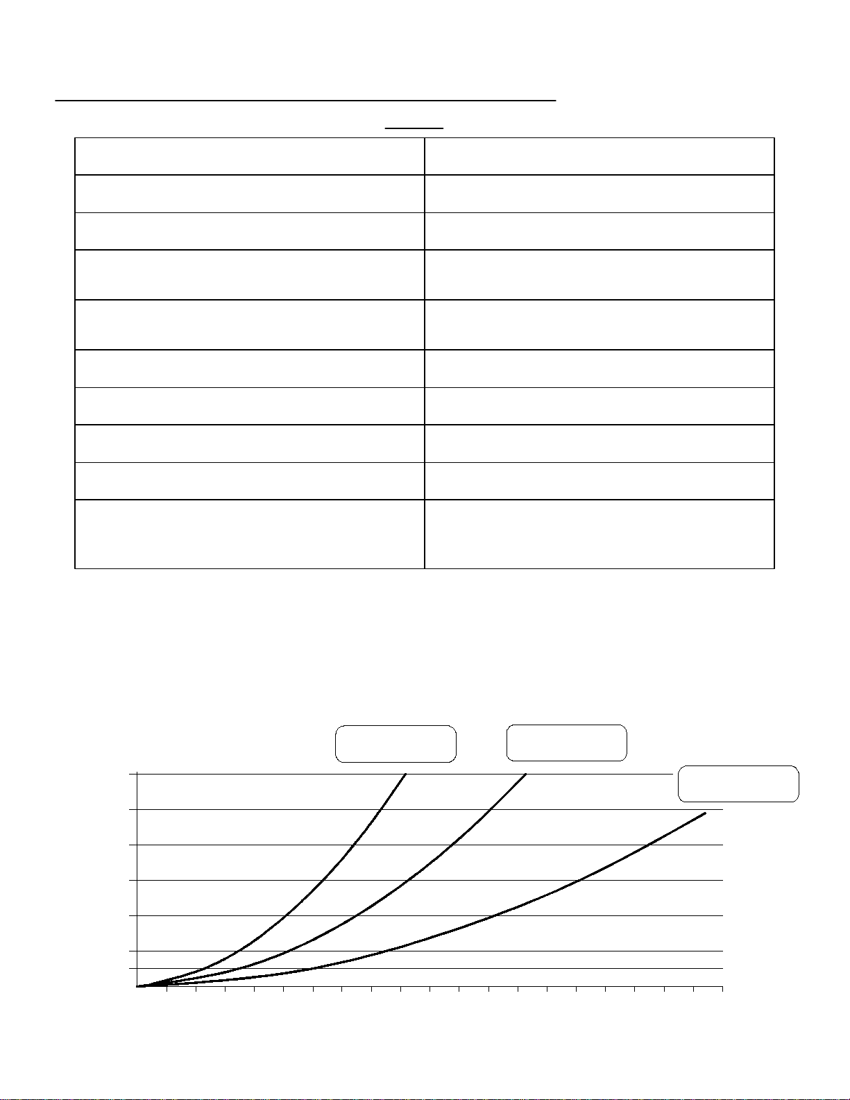
3. Maximum permitted variation in either supply pressure in order to control the mixed water supply
temperature to within ± 3°F. Excessive changes in supply pressures may cause changes in
mixed water supply temperature.
Mixed TemperatureMixed Temperature
of 140°F
60
50
40
30
20
Pressure Drop (psi)
10
5
of 120°F
Mixed Temperature
of 95°F
1234567891011121314151617181920
Flow (gpm)
Page 2
Page 3
Remove all components from the
package and check that all required
components are included. The required
components are: mixing device, cold
water tee, flexible metal connector and
thermostrip (see Figure 1).
This kit may have two flexible
connectors provided for water heaters
with top water course connections at 8
inch and 11 inch spacing. Use the
appropriate flexible metal connector.
Instructions
Mixing
device
Flexible metal
connector
Cold water tee
Figure 1
WATER CONNECTIONS
The mixing device, cold water tee, flexible metal connector and thermostrip are integral parts of the
water heater. This system improves hot water deliverability and must be installed. The integrated
appliance is designed for a maximum working pressure of 150 p.s.i. (1034 kPa). Refer to the
“Water Connections” section of the installation and operation instruction manual supplied with the
water heater for additional instructions.
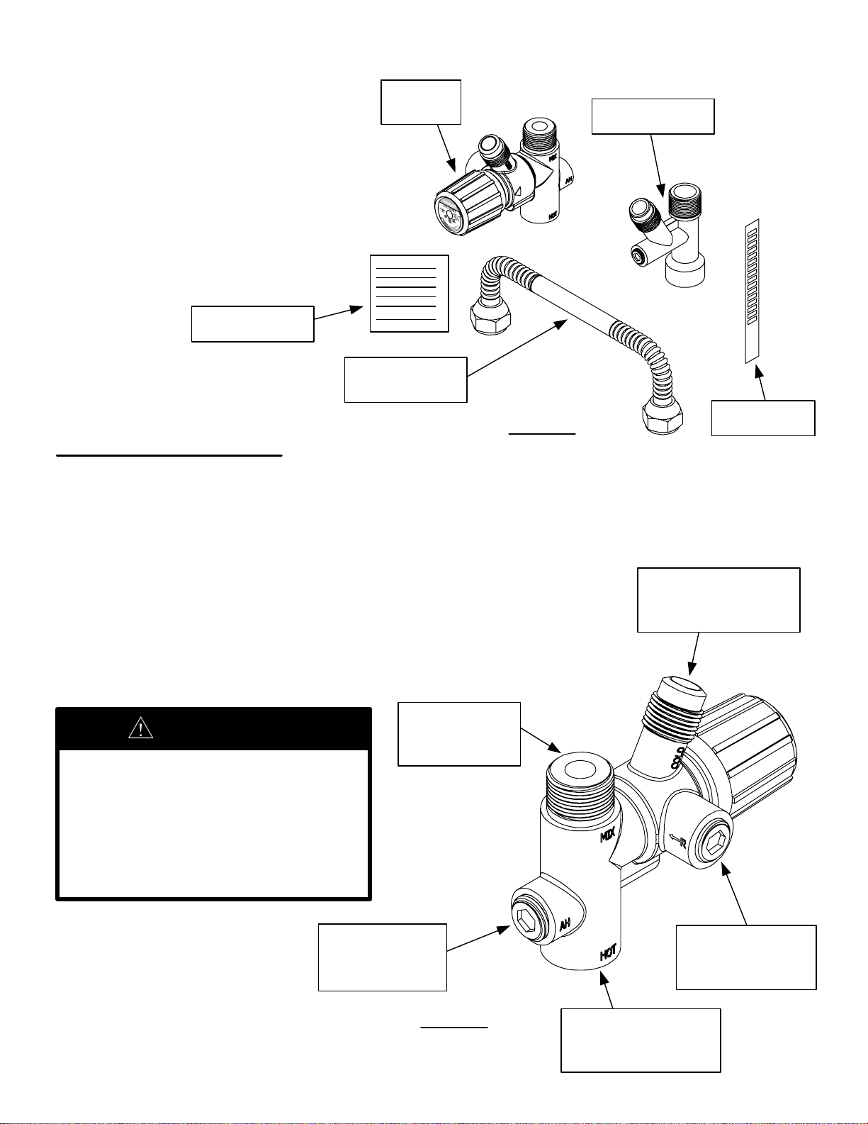
The mixing device is equipped with a ½” NPT alternate hot water
outlet that draws unmixed very hot water from the tank. This outlet
should be used if unmixed very hot water is needed at specific
fixtures (laundry, dishwasher, etc…). It is also equipped with a ½”
NPT optional recirculation inlet that must be utilized in conjunction
with a check valve if a recirculation loop is used (see Figure 2).
(MIX) ¾" NPT
WARNING
If recirculation loop water is returned
to the water heater at any location
other than the optional recirculation
inlet, unmixed very hot hot water is
exposed to the recirculation loop.
Do not return recirculation loop to
any other location other than “R”
inlet of the mixing device.
Mixed water
IMD Components
(COLD) Cold water
inlet from cold
outlet
Thermostrip
water tee
(AH) ½" NPT
Alternate hot
water outlet
Mixing Device
Page 3
Figure 2
(R) ½" NPT
Optional
recirculation inlet
(HOT) ¾" NPT Hot
water inlet from
water heater
Page 4

WATER CONNECTIONS CONTINUED...
The cold water tee is equipped with a ¼” NPT optional
cold water outlet that draws cold water prior to the water
heater (see Figure 3). This outlet may be used to
connect cold water to refrigerator ice makers or other
low flow applications.
Cold water outlet
to mixing device
¼" NPT Optional
cold water outlet
ASSEMBLY PROCEDURE
Figure 3
Cold water Tee
¾" NPT Cold
water inlet
¾" NPT Cold water
outlet to water heater
1. Twist and pull thread protectors with pliers or large regular
screw driver to remove them from flexible metal connector as
shown in Figure 4.
CAUTION
Do not damage flared connectors
or threads on connector nuts
when removing thread protectors.
Flare co nnectors
with thread
protectors
Flexible metal
connector
Figure 4
Flexible Metal Connector
Page 4
Page 5

ASSEMBLY PROCEDURE CONTINUED...
2. Install the cold water tee onto the cold water inlet of the
water heater. If installing on a water heater with 1" inlet
fitting, use 1" NPT to ¾" NPT brass reducer bushing and
brass nipples. Tighten until leak tight and facing the front of
the water heater as shown in Figure 5.
Cold water tee
Water heater
cold water inlet
Front of water
heater
Installing Cold Water Tee
3. Install the mixing device onto the hot water outlet
of the water heater. If installing on a water heater
with 1" outlet fitting, use 1" NPT to ¾" NPT brass
reducer bushing and brass nipples. Tighten until
leak tight and facing the front of the water heater as
shown in Figure 6.
Mixing device
Water heater
hot water
outlet
Figure 5
Front of water
heater
Figure 6
Installing Mixing Device
Page 5
Page 6

ASSEMBLY PROCEDURE CONTINUED...
Flexible metal
4. Install the flexible metal connector
to the mixing device and cold water
tee as shown in Figure 7. Tighten
flare connectors until leak tight.
Mixing device Cold water tee
At this time the IMD should be leak tight. Continue installation of potable water system as indicated
in the installation and operation instruction manual supplied with the water heater.
Flare connector
Figure 7
Installing Flexible Metal Connector
connector
Once potable water system has been completely installed, install the thermostrip on the mixed water
outlet pipe no more than 10 inches from mixing device as shown in Figure 8.
Thermostrip
(AH)
Alternate hot
water outlet
(R) Optional
recirculation
inlet
(MIX) Mixed
water outlet
Cold water inlet
Optional cold
water outlet
Check Valve
Figure 8
Installing Thermostrip
Page 6
Page 7

IMD CARE AND MAINTENANCE
WARNING
Hotter water increases the risk of scald injury. Scalding may occur within 5 seconds at a
setting of 140°F (60°C). Water temperature over 125°F (52°C) can cause burns or death
from scalds. Children, disabled and the elderly are at highest risks of being scalded.
Please feel the water before bathing or showering.
WARNING
SCALDING
This water heater can deliver scalding temperature water at any faucet in the system. Be
careful whenever using hot water to avoid scalding injury. By setting the thermostat on
this water heater to obtain an increased water temperature, you may create the potential
for scald injury. To protect against injury, you should install an ASSE approved
thermostatic mixing valve (a device to limit the temperature of water to protect against
scald injury via mixing hot and cold water supply) in the water system. This valve will
reduce point of discharge temperature in branch supply lines. This water heater was
shipped with an ASSE approved thermostatic mixing valve. Install this valve according to
the directions in the mixing device container. DO NOT OPERATE THIS WATER HEATER
WITHOUT AN ASSE APPROVED THERMOSTATIC MIXING DEVICE. If this water heater
was shipped without an ASSE approved thermostatic mixing valve, contact the
manufacturer.
APPROXIMATE
TIME/TEMPERATURE
RELATIONSHIP IN SCALDS
120°F More than 5 minutes
125°F 1 ½ to 2 minutes
130°F About 30 seconds
135°F About 10 seconds
140°F Less than 5 seconds
145°F Less than 3 seconds
150°F About 1 ½ seconds
155°F About 1 second
TEMPERATURE ADJUSTMENT
Prior to adjusting the IMD, the water heater must be operational and deliver hot water within the
Water Heater Outlet Temperature Range (100°F - 180°F) (38 - 82°C). Note that the water
heater thermostat is factory set at approximately 120°F (49°C) or lower. For proper operation,
the temperature setting on the water heater may be increased. Prior to measuring the Mixed
Water Supply Temperature, allow the water heater to recover from the thermostat adjustment.
Measure the Mixed Water Supply Temperature at the nearest faucet supplied by the integrated
mixing device. A flow rate of 1 to 1.5 gpm (4 to 6 L/min) is recommended.
An accurate temperature measuring device such as a thermometer must be used to ensure that
a suitable temperature of mixed water is achieved.
Allow the water to run until a steady temperature is reached. The amount of time necessary is
dependant on the outlet's location to the water heater.
Page 7
Page 8

TEMPERATURE ADJUSTMENT CONTINUED...
1. The Mixed Water Supply Temperature may require adjustment. The IMD is set at approximately
120°F when the arrow on the hand wheel and the arrow on the casting are aligned.
a. To Increase Mixed Water Supply Temperature: Depress and rotate the hand wheel
counter clockwise until the desired set point is reached (see Figure 9). Refer to thermostrip
temperature reading for desired set point (hot water must be flowing at a minimum of 1 gpm
to accurately read thermostrip). Ensure the hand wheel snaps back to the locked position
once desired set point is reached.
b. To Decrease Mixed Water Supply Temperature: Depress and rotate the hand wheel
clockwise until the desired set point is reached (see Figure 9). Refer to thermostrip
temperature reading for desired set point (hot water must be flowing at a minimum of 1 gpm
to accurately read thermostrip). Ensure the hand wheel snaps back to the locked position
once desired set point is reached.
2. Verify that the desired set point is reached by allowing an appropriate
amount of water to run from the nearest faucet supplied by the IMD.
Hand wheel
Rotate clockwise
to decrease mixed
water temperature
Depress
Adjusting Mixed Supply Temperature
Figure 9
CHECKING / SERVICING THIS DEVICE
Arrow on
casting
Arrow on
hand wheel
Rotate counter
clockwise to increase
mixed water
temperature
It is recommended that the IMD is checked annually to ensure proper system capabilities.
Where adverse water conditions are applied, more frequent intervals are recommended.
In checking the mixed water supply temperature, use the same faucet used in the initial
installation temperature adjustment.
There may be some variation in the water temperature from the IMD due to seasonal
temperature variations in the cold water supply.
If the water supply is of poor quality, the internal components may jam requiring an
additional filter or strainer to be fitted to the system. Contact a plumbing professional for
appropriate materials and installation.
Page 8
 Loading...