

Page 1
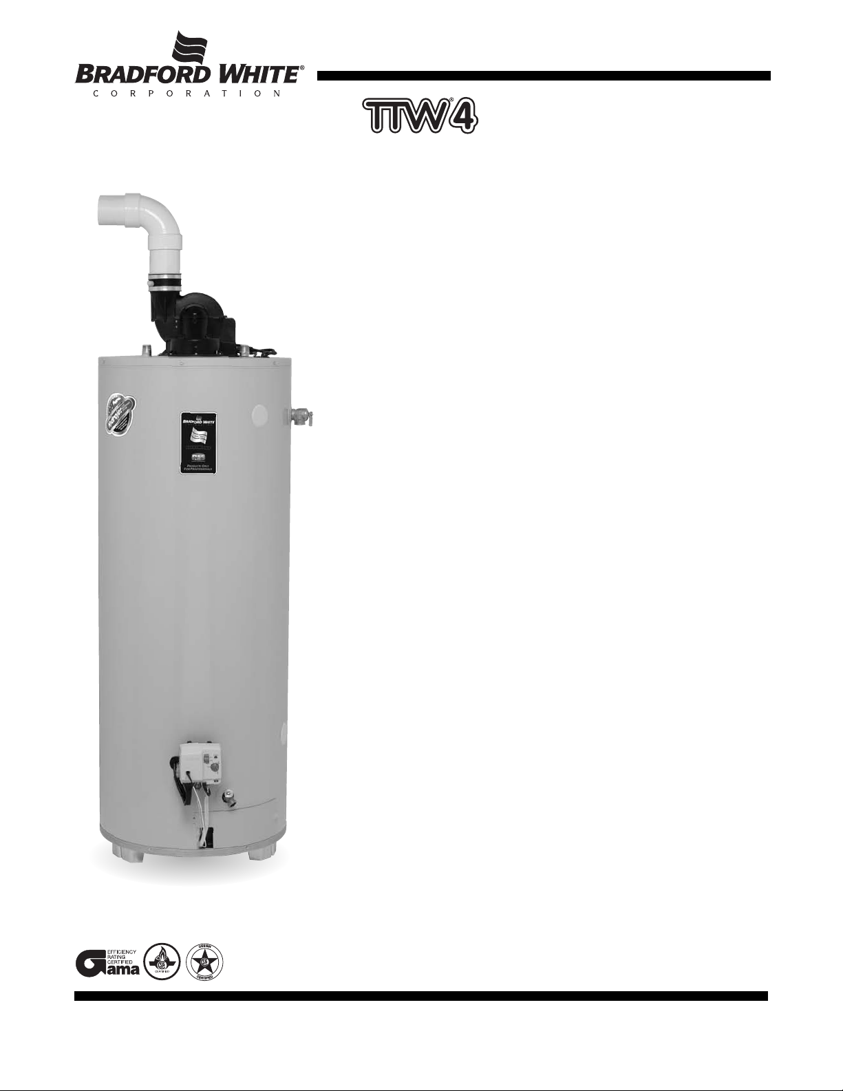
Light Duty Commercial Energy Saver Gas
Through-The-Wall Water Heaters
The TTW4 Models Feature:
■ Power Vented Heater—Designed for installations where atmospheric units
cannot be used. Exhaust gases are vented under positive pressure directly
out of the building through the wall or the roof.
■ Powerful Blower Motor—Our design has higher torque for greater
resistance to outside winds and the power to eliminate problems with difficult
venting situations. This significantly quieter motor runs cooler for a
considerably longer operational life.
■ Spark-to-Pilot Ignition System—Eliminates the constant burning pilot used
on other water heaters. This device results in savings of pilot gas during
standby periods (110 VAC required to heater).
■ PVC, ABS or CPVC Venting—Horizontal and vertical venting up to 60
equivalent feet for 3" pipe, and up to 90 equivalent feet for 4" pipe. See
TW4-65S-65B-3N
reverse side for specifics.
■ Vitraglas
corrosive effects of hot water by a ceramic porcelain-like coating. The
exclusive high silica ceramic lining provides a tough interior surface for our
water heater tank.
■ More precise temperature control—with an adjustable temperature up to
180° F. Not recommended for 180° F sanitizing.
■ Steel Tank—Heavy gauge steel automatically formed, rolled and welded to
assure a continuous seam for glass lining.
■ Side connections—Side tappings allow easy connection for space heating
applications.
■ Protective magnesium rod—Provides added protection against corrosion
for long trouble-free service.
■ Factory installed Hydrojet
sediment reducing device. Helps prevent sediment build up in tank. Increases
first hour delivery of hot water while minimizing temperature build up at top of
tank.
■ Factory installed Heat T
reduces heat loss in piping and eliminates the potential for noise generation.
■ Water Connections—3⁄4" NPT factory installed true dielectric fittings.
Extends water heater life and eases installation.
■ 2" Non-CFC Foam Insulation—Covers the sides and top of tank to save
energy by retarding loss of heat. Also increases jacket rigidity.
(The TW4-65S-65B-3N has 1" of foam insulation.)
■ Electronic Gas Control Valve—The integrated, immersion gas control valve
offers more precise temperature control for higher first hour delivery and also
allows water temperature adjustment without removing the cover. The control
is equipped with an LED display to aid in star
■ Brass Drain Valve.
■ T&P Relief Valve included
■ Stainless Steel Flue baf
absorbed in the lower portion of tank. Reduces air movement in the heater
during standby periods to retard heat loss up the flue.
■ Design certified by CSA International (formerly AGA and CGA).
®
Lining—Bradford White water heater tanks are protected from the
®
Total Performance System—Cold inlet
raps—
Design incorporates a flexible disk that
t-up and diagnostics.
fle—
Designed to maximize the amount of heat
355-B 0506
6-Year Limited Warranty on Component Parts / 6 or 10-Year Limited Tank Warranties.
For more information on warranty, please visit www.bradfordwhite.com
oducts installed in USA, Canada and Puer
For pr
copy of the warranty included with the heater.
TENTS:
ACTURED UNDER ONE OR MORE OF THE FOLLOWING U.S. P
MANUF
(B1)5,341,770; 5,660,165; 5,596,952; 5,682,666; 4,904,428; 5,023,031; 5,000,893; 4,669,448; 4,829,983; 4,808,356; 5,115,767; 5,092,519; 5,052,346; 4,416,222; 4,628,184; 4,861,968; 4,672,919; Re. 34,534.
OTHER U.S. AND FOREIGN PATENT APPLICATIONS PENDING. CURRENT CANADIAN PATENTS: 1,272,914; 1,280,043; 1,289,832; 2,045,862; 2,112,515; 2,108,186; 2,107,012; 2,092,105.
itraglas
V
®
and Hydr
®
ojet
e registered trademarks of Bradford White
ar
A
5,954,492; 5,761,379; 5,943,984; 5,081,696; 5,988,117; 6,142,216; 5,199,385; 5,574,822; 5,372,185; 5,485,879; 5,277,171;
®
Corporation.
©2006, Bradford White Corporation. All rights reserved. Printed in U.S.A.
to Rico. Some states do not allow limitations on warranties. See complete
Page 2
N
ATURAL GAS AND LIQUID PROPANE GAS
M
odel
Number
Capacity
65 65,000 22 3 22214
1
⁄2 603⁄4541⁄2 611⁄2 271⁄4121⁄2701⁄8 541⁄4
F
F
loor to
Space
Heating
R
eturn
in.
G
F
loor to
Space
Heating
O
utlet
in.
H
F
loor
to
Heater
T
op
in.
K
D
epth
in.
J
F
loor
to
Water
C
onn.
in.
Approx.
S
hipping
Weight
lbs.
E
F
loor
to
Gas
C
onn.
in.
A
F
loor to
Vent
Conn.
in.
D
F
loor to
T&P
Conn.
in.
C
V
ent
Size
in.
B
J
acket
Dia.
in.
Gal.
U.S.
Input
N
at.
BTU
63
Input
LP
BTU
Recovery
1
00°F Rise*
75 76,000
63,000
75,100 26 3 27714
1
⁄2 303⁄4567⁄8 581⁄4491⁄2111⁄2491⁄2663⁄874
TW4-50S-65B-3N
T
W4-65S-65B-3N
TW4-75S-76B-3N
T
W4-50S-65B-3N
TW4-65S-65B-3N
T
W4-75S-76B-3N
Model
Number
C
apacity
Liters
246 19 231
F
Floor to
Space
H
eating
Return
mm.
G
Floor to
Space
H
eating
Outlet
mm.
H
Floor
to
H
eater
Top
mm.
K
Depth
mm.
J
Floor
to
W
ater
Conn.
mm.
A
pprox.
Shipping
Weight
kg.
E
Floor
to
G
as
Conn.
mm.
A
Floor to
Vent
C
onn.
mm.
D
Floor to
T&P
C
onn.
mm.
C
Vent
Size
mm.
B
Jacket
Dia.
mm.
Input
Nat.
kW
18.5
Input
LP
kW
53
G
PH
I
mp.
Hour
Liters/
R
ecovery
56°C Rise*
2
84 22.3 276
1780
1
685
560
6
60
76
7
6
1380
1
260
320
2
92
368
3
68
1385
1
257
1543
1
445
1562
1
480
692
7
81
101
1
2622
62
M
eet or exceed ASHRAE 90.1b (current standard) C.E.C. Listed
8
0% Recovery Efficiency
4
8
54
Gal.
Imp.
62
4
0 65,000 60,000 66 22
7
⁄8
3
18014
1
⁄2 5
7512758
1
⁄41
2
1
⁄25
0
3
⁄46
3
61
73
5
8
182 219 1700 560 1290 320 368 1295 1448 1480 686 827617.619
53
N
at.
G
PH
G
as
N
at.
51
G
PH
I
mp.
61
48
L
P
G
PH
R
ec.
L
P
LP
238
Hour
Liters/
2
80
238
Nat.
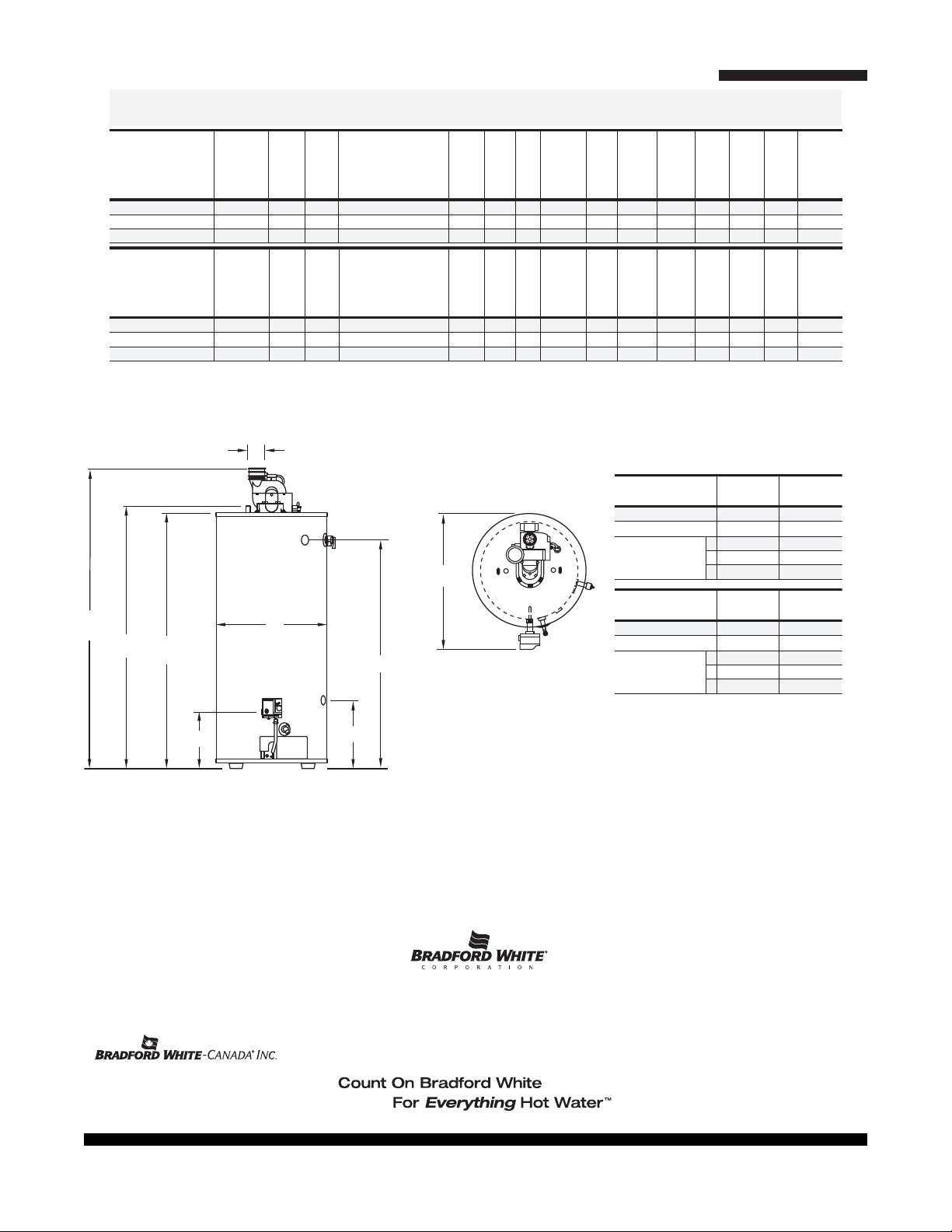
Light Duty Through-The-Wall Gas Water Heater
C
A
J
H
E
F
B
D & G
K
3" Vent Pipe
T
W4-50S-65B
TW4-65S-65B
TW4-75S-76B
TW4-50S-65B
TW4-65S-65B
TW4-75S-76B
6
0 ft.
7
ft.
55 ft.
50 ft.
45 ft.
5
0 ft.
7
ft.
45 ft.
40 ft.
35 ft.
M
ax. Equivalent Length
M
in. Equivalent Length
Number 1
of 2
90° Elbows 3
4" Vent Pipe
90 ft.
15 ft.
85 ft.
80 ft.
75 ft.
80 ft.
15 ft.
75 ft.
70 ft.
65 ft.
Max. Equivalent Length
Min. Equivalent Length
Number 1
of 2
90° Elbows 3
All propane heaters are equipped with a cast iron burner. To order a propane heater remove the suffix "B" and change the suffix "N" to "X".
For 10 year models, change suffix from “6” to “10”.
*Based on manufacturers rated recovery efficiency.
110 V.A.C. Required for Power Venting / 110 V.A.C. 60HZ 3.1 Amperes
All natural gas models meet SCAQMD Requir
General
All gas water heaters ar
All water connections are 3⁄4" NPT (19mm) on 11" (279mm) centers, all gas connections are 1⁄2" (13mm).
All models design certified by CSA International (formerly AGA/CGA), ANSI Z-21.10.1 and peak performance rated.
Dimensions and specifications subject to change without notice in accordance with our policy of continuous product improvement.
Suitable for W
Toxic chemicals, such as those used for boiler treatment, shall NEVER be introduced into this system. This unit may NEVER be connected to any existing
heating system or component(s) pr
Sales 800-538-2931 ●Fax 215-641-1670 / Technical Support 800-334-3393 ●Fax 269-795-1089 ●Warranty 800-531-2111 ●Fax 269-795-1089
355-B 0506
ements. Meets NAECA Requir
ements.
e certified at 300 PSI (2068 kPa) test pressure and 150 PSI (1034 kPa) working pressure.
ater (Potable) Heating and Space Heating
For U.S. and Canada field ser
International:
eviously used with a non-potable water heating appliance.
vice, contact your pr
Telephone 215-641-9400 ●Telefax 215-641-9750 / Fax on Demand 888-538-7833 / www.bradfordwhite.com
Sales / T
echnical Suppor
©2006, Bradford White Corporation. All rights reserved.
ofessional installer or local Bradfor
t
866-690-0961 / 905-238-0100 ●Fax 905-238-0105 / www
Ambler
, P
A
d White sales r
epresentative.
.bradfor
dwhitecanada.com
Printed in U.S.A.
 Loading...