

Page 1
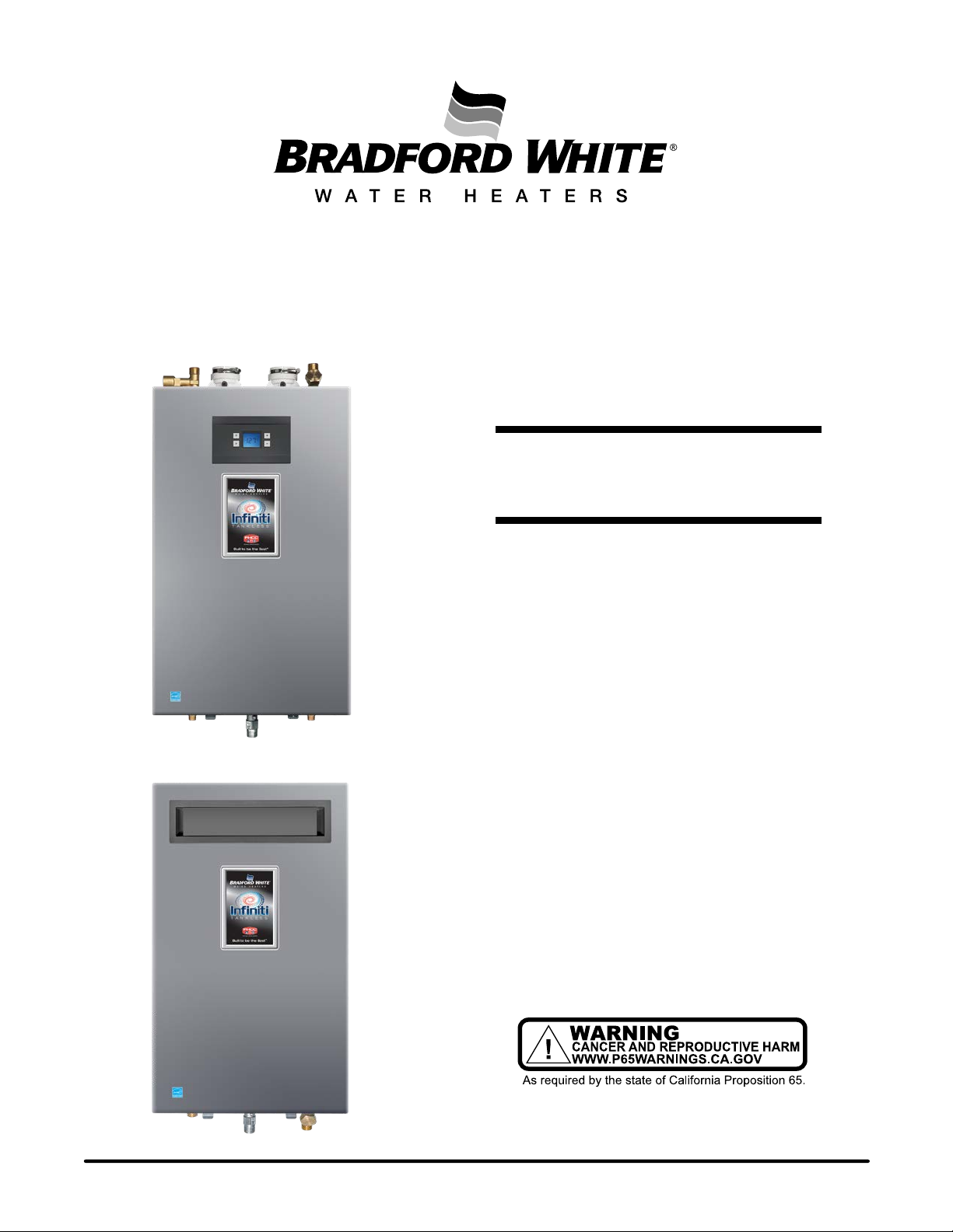
Infiniti® Series Tankless
(Condensing) Gas Water Heater
SERVICE
MANUAL
Troubleshooting Guide
and Instructions for Service
(To be performed ONLY by
qualified service providers)
(Indoor)
(Outdoor)
Models Covered
by This Manual:
Indoor Gas:
RTG-K-160-N1
RTG-K-199-N1
RTG-L-160-N1
RTG-L-199-N1
Outdoor Gas:
RTG-K-160-N2
RTG-K-199-N2
TRAINING AND SERVICE INFORMATION
This document is restricted to exclusive use
by the official service partners.
Indoor Propane:
RTG-K-160-X1
RTG-K-199-X1
RTG-L-160-X1
RTG-L-199-X1
Outdoor Propane:
RTG-K-160-X2
RTG-K-199-X2
Manual 238-53328-00B REV 6/21
Save this manual for future reference
Page 2

Table of Contents
1. INTRODUCTION ......................................................................................... 3
2. APPLIANCE DESCRIPTION ...................................................................... 3
2.1 APPLIANCE DESIGNATION ..................................................................................................... 3
2.2 AVAILABLE ACCESSORIES ..................................................................................................... 4
3. INSTALLATION............................................................................................ 5
3.1 APPLIANCE MOUNTING ON THE WALL .................................................................................. 5
3.2 WATER CONNECTIONS ......................................................................................................... 7
3.3 GAS CONNECTION ................................................................................................................ 8
3.4 APPLIANCE PERFORMANCE .................................................................................................. 9
4. COMPONENTS OVERVIEW ................................................................... 10
4.1 CONTROL PANEL FOR USER (INDOOR VERSION) ............................................................... 11
4.2 CONTROL PANEL INBUILT (OUTDOOR VERSION) ............................................................... 17
4.3 CONDENSATE SIPHON ........................................................................................................ 21
4.4 HEAT CELL .......................................................................................................................... 22
4.5 GAS MANIFOLD ................................................................................................................... 23
4.6 FAN ...................................................................................................................................... 27
4.7 GAS VALVE.......................................................................................................................... 28
4.8 HEAT EXCHANGER .............................................................................................................. 29
4.9 WATER VALVE ..................................................................................................................... 30
4.10 CIRCULATION PUMP (L-SERIES ONLY) ............................................................................ 31
4.11 WATER TEMPERATURE SENSORS ................................................................................... 35
4.12 BOX TEMPERATURE SENSOR .......................................................................................... 35
4.13 ELECTRODES ................................................................................................................... 36
5. WORKING PRINCIPLE / ELECTRIC MEASUREMENTS .................... 38
6. AFTER SALES SERVICE ......................................................................... 48
6.1 PCB REPLACEMENT: .............................................................................................. 48
7. MAINTENANCE ......................................................................................... 56
8. TROUBLE SHOOTING ............................................................................. 61
Page 2
2
Page 3
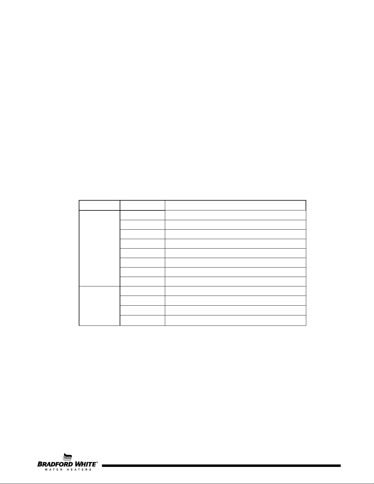
Segment
Model #
Description
RTGK160N1
160 KBTU/NATURAL GAS/INDOOR
RTGK199N1
199 KBTU/NATURAL GAS/INDOOR
RTGL160N1
160 LBTU/NATURAL GAS/INDOOR
RTGL199N1
199 LBTU/NATURAL GAS/INDOOR
RTGK199X1
199 KBTU/PROPANE/INDOOR
RTGK160X1
160 KBTU/PROPANE/INDOOR
RTGL160X1
160 LBTU/PROPANE/INDOOR
RTGL199X1
199 LBTU/PROPANE/INDOOR
RTGK199N2
199 KBTU/NATURAL GAS/OUTDOOR
RTGK160N2
160 KBTU/NATURAL GAS/OUTDOOR
RTGK199X2
199 KBTU/PROPANE/OUTDOOR
RTGK160X2
160 KBTU/PROPANE/OUTDOOR
1. Introduction
This manual is a complement to the instruction/operation manual delivered with the appliance, with
the main important technical details that are relevant for the official service partners and trainers
in the country.
2. Appliance Description
This appliance is a fan pressurized gas water heater offering a wide range of modulation and
installation advantages with both indoor and outdoor models available.
2.1 Appliance Designation
The designation allows the identification of the main characteristics of the units, especially when a report is
needed through Bradford White Tech Services.
Infiniti Tankless™ K and L Series
INDOOR
OUTDOOR
Table 1 – Appliance Identification
Page 3
3
Page 4
Page 4
Activation
Deactivation
T
box
≤ 5ºC / 41ºF
T
box
≥ 10ºC / 50ºF
2.2 Available Accessories
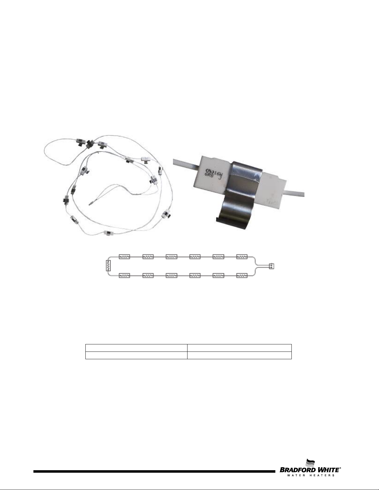
Anti-Freeze Kit
Allows the protection of the appliance against water freezing inside of its pipes / heat exchanger.
The anti-freeze kit can be used where ambient temperatures are as low as -30°F/-35°C for short
periods of time.
Additional measures must be taken to the surrounding pipes connected to the unit in case it is
installed in a place where freezing temperatures are constant.
The heating elements in the Anti-Freeze kit are protected by ceramics and are clipped to the copper
pipes.
Figure 1 – Anti-Freeze Kit
The kit includes 16 resistances for the indoor version and 13 resistances for the outdoor version,
which activate under conditions from table 2. Each resistance has +/- 16W of expected dissipated
power.
Table 2 – Anti-freeze activation conditions
4
Page 5
Requisite
Confirmation
Appliance is levelled and in the vertical position?
Delivered accessories are used accordingly?
Appliance is supported exclusively by the wall mounting and not by
hydraulic and/or gas connections?
3. Installation
The installation manual of each product must be checked and used by the installer to optimize and
leave the appliance in correct operation conditions.
Check Lists for Technicians/Installers:
3.1 Appliance Mounting on the Wall
Table 3 – Check List for Mounting
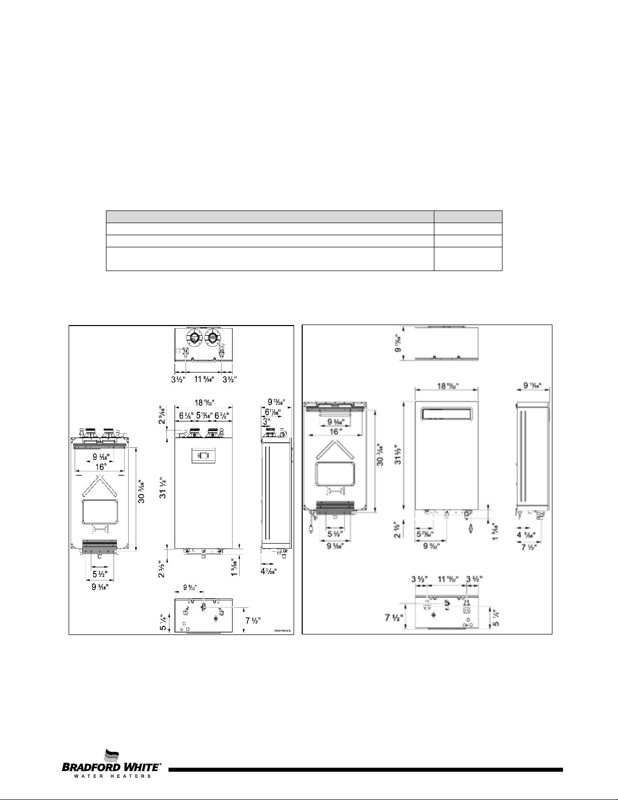
Figure 2 – Pre-installation distances for Indoor appliance (left) and outdoor appliance (right)
Page 5
5
Page 6
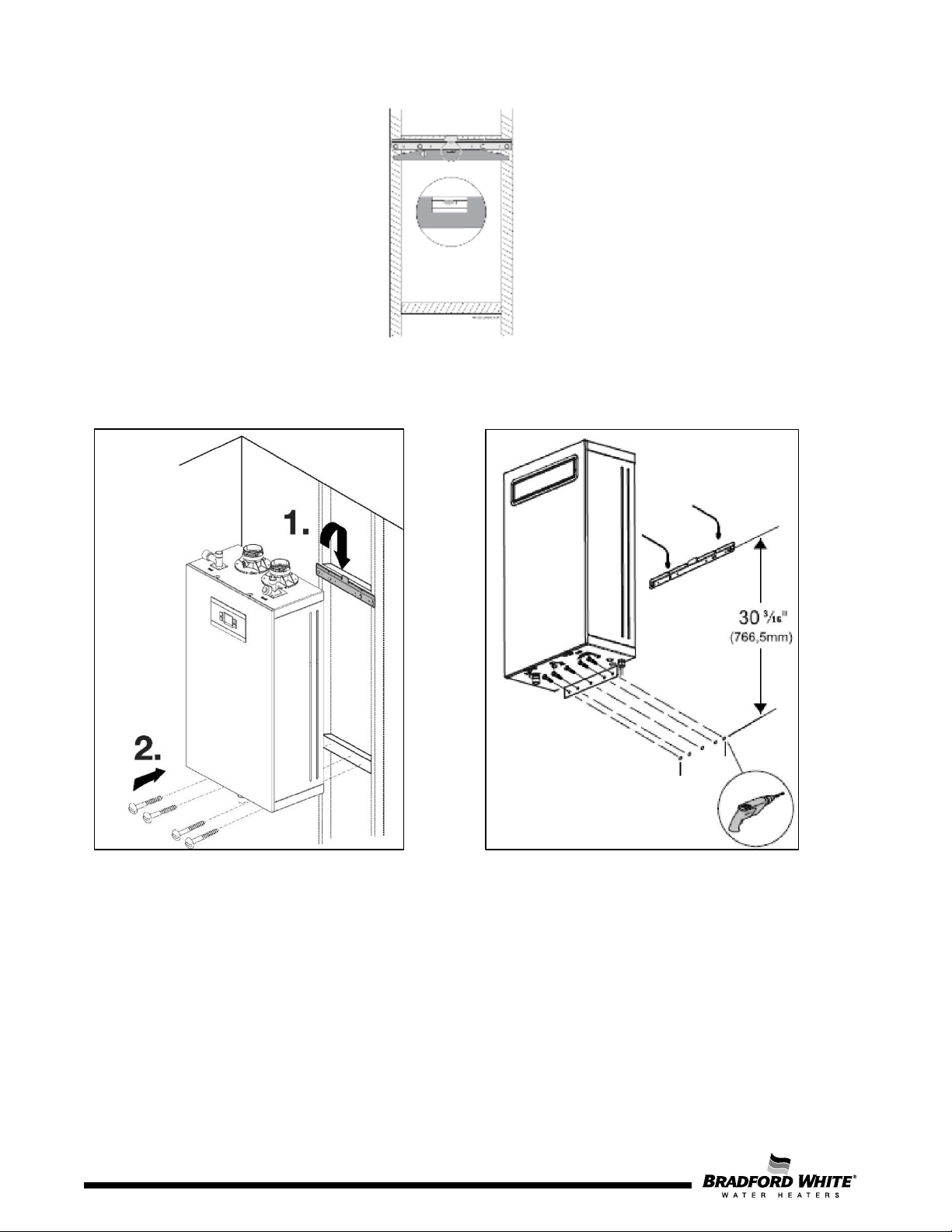
Figure 3 – Wall mounting preparation using supplied wall hung bracket
Figure 4 – Wall mounting for indoor appliance (left) and outdoor appliance (right)
Page 6
6
Page 7
Requisite
Observations
Confirmation
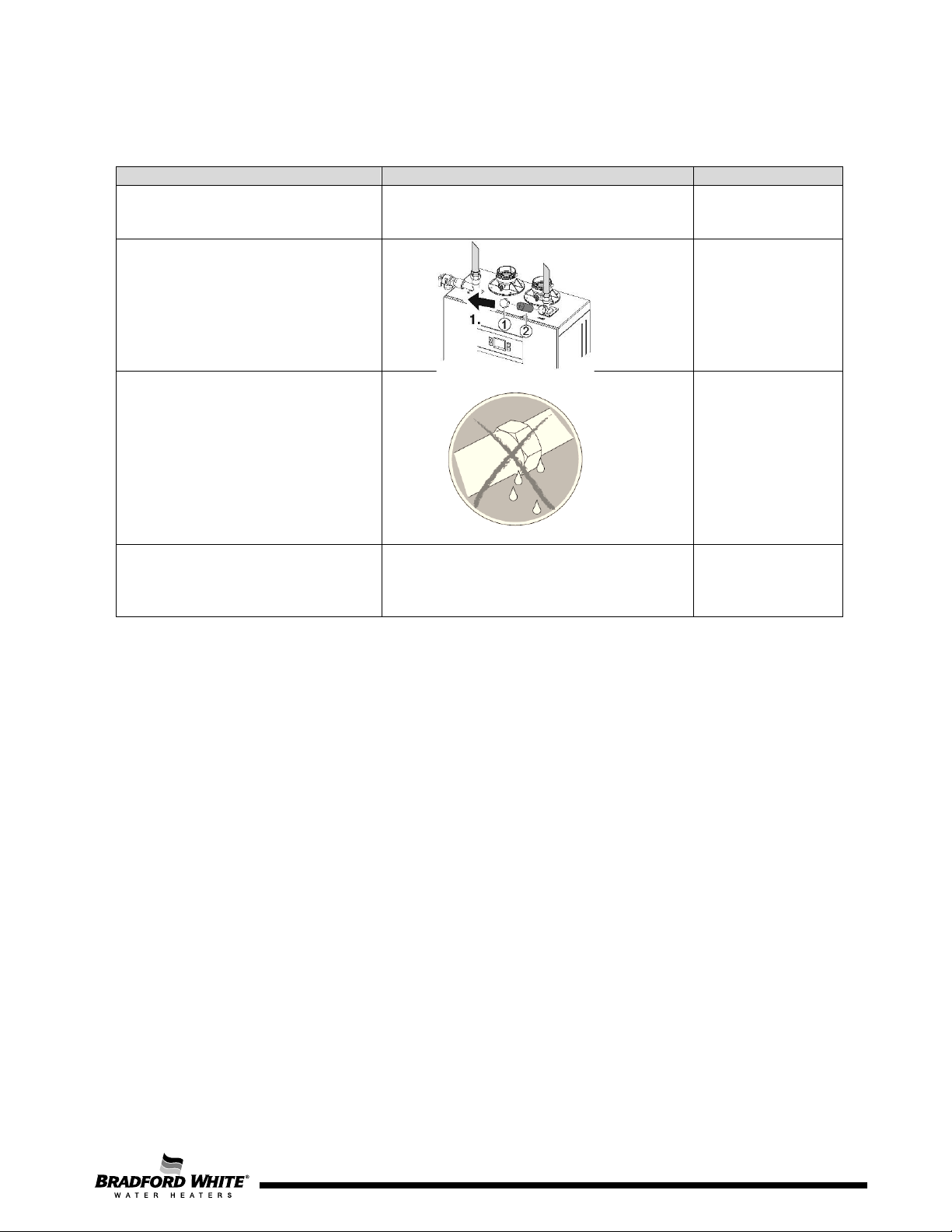
Water pipes were cleaned
the appliance?
- Minimum pressure: 1.2 bar / 18
PSI
3.2 Water Connections
before being connected to
Inlet water filter was checked
and is cleaned, ensuring the
necessary water flow rate?
Accessories for water
connections are adequate
and without water leak?
Water pressure and flow are
according to the appliance
specifications?
Table 4 – Check List for Water Connections
PSI
- Maximum pressure: 10 bar / 150
Page 7
7
Page 8
8
Requisite
Confirmation
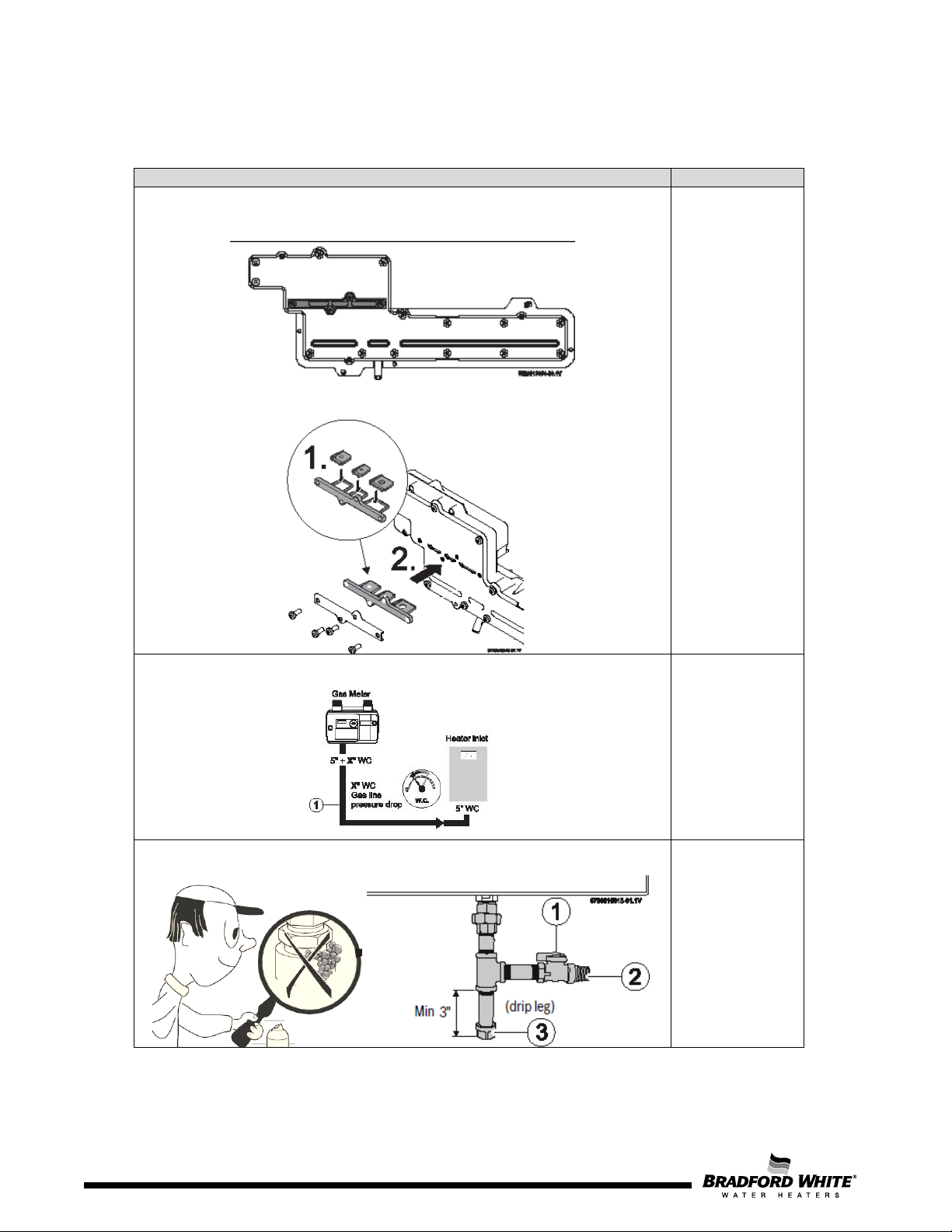
The appliance is suitable for the available gas type?
Pressure reducer and gas pipe are adequate for the required pressure and
Accessories for gas connection are adequate and according to the country
3.3 Gas Connection
Unit Supplied as NG (without gas flow restrictors)
Unit set up for LP (with gas flow restrictors)
gas flow? Refer to manual recommendations.
specification/standards?
Table 5 – Check list for Gas Connections
8
Page
Page 9
GAS
MANOMETER
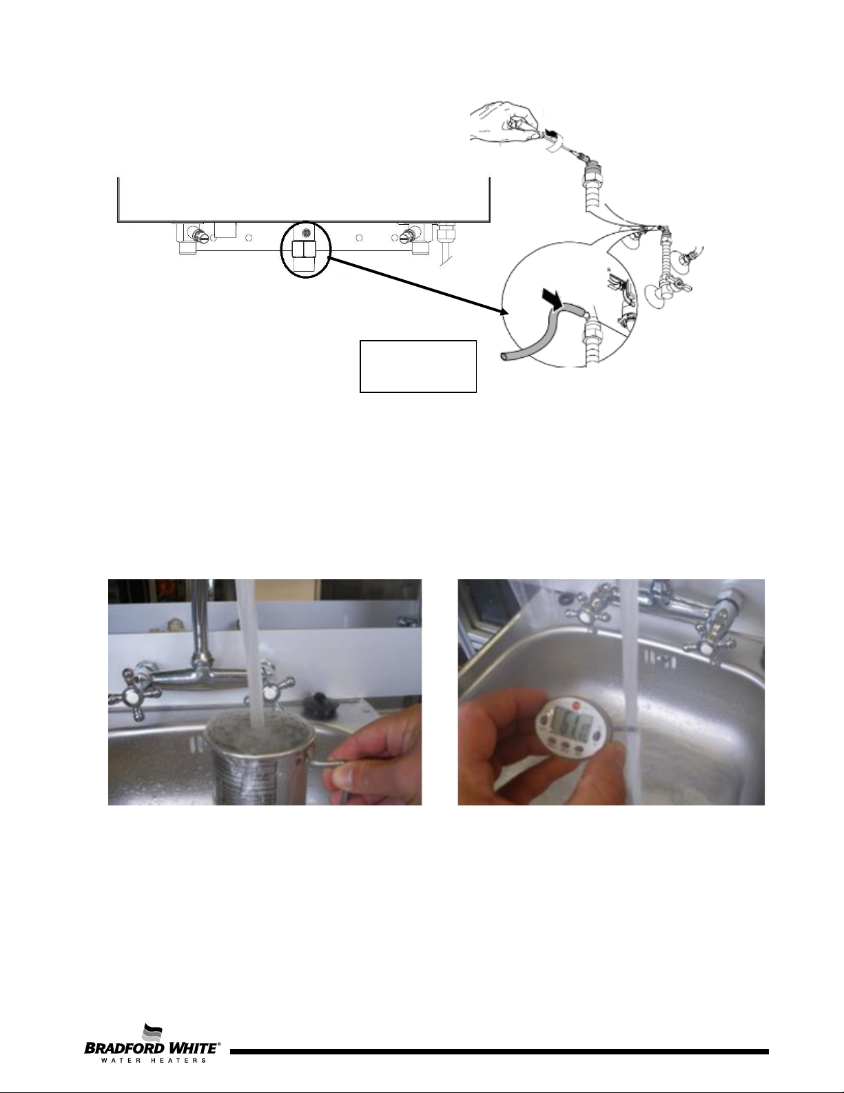
Figure 5 – Manometer pipe connection to measure static/dynamic gas supply pressure
3.4 Appliance Performance
Measure water flow and temperature increase to check temperature and instantaneous water flow,
assuring correct operation of the appliance.
Figure 6 – Use of Water Flow Meter and Thermometer
9
Page 10
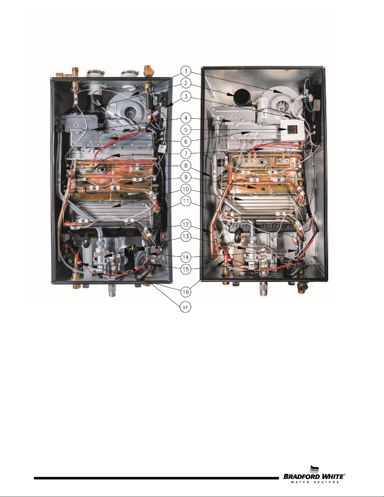
10
1 – Fan
9 – Primary heat exchanger
2 –
10 –
3 – Control unit
11 – Condensate collector
4 – Gas restrictor
12 – Bypass valve
5 – HMI for installer (outdoor version)
13 – Gas valve
6 – Manifold
14 – Water valve (Stepper motor+Flow sensor)
7 – Burner
15 – Temperature sensor (inlet water)
8 – Gas tube
16 – Temperature sensor (outlet water)
17–
4. Components Overview
Exhaust tube
Figure 7 – Internal View of Model – Indoor: L-Series (left) and Outdoor K-Series (right)
Secondary heat exchanger
Built-in recirculating pump (L-Series only)
10
Page
Page 11
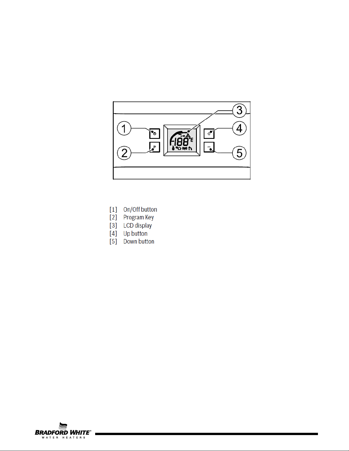
4.1 Control Panel for User (Indoor Version)
The control panel, located on the front cover of the appliance, allows the final user to control the
operations needed. The following figures show the overall control panel and the display icons,
respectively. See Table 8 for more display icon information.
Figure 8 – Control Panel on the Front Cover of the Appliance (Indoor Version)
11
Page 12
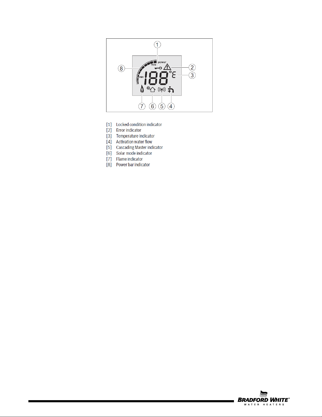
12
Figure 9 – Display LCD Description
Control Panel Operation:
Power:
• To start the appliance, press the On/Off button.
• To shut down the appliance, press the On/Off button again.
Reset Errors:
• Some error codes can be solved by resetting the appliance. To do this, press and hold the
On/Off button for more than 3 seconds. The appliance will initiate the start-up sequence.
Set Water Temperature:
• By default, the unit is set for 120 °F.
• Press the Up or Down button until you reach the desired temperature.
• Once the user has selected the desired temperature and would like to set this as the default
temperature, press the P button for 3 seconds. The selected temperature will blink. Once this
is completed, the default temperature is saved.
• If the desired temperature setpoint is above the limit of the appliance, the user must change
the Setpoint Limit (continue reading below).
12
Page
Page 13

Display
Description
P4
Information
P7
Gas Type
P9
Purge
SA
Settings
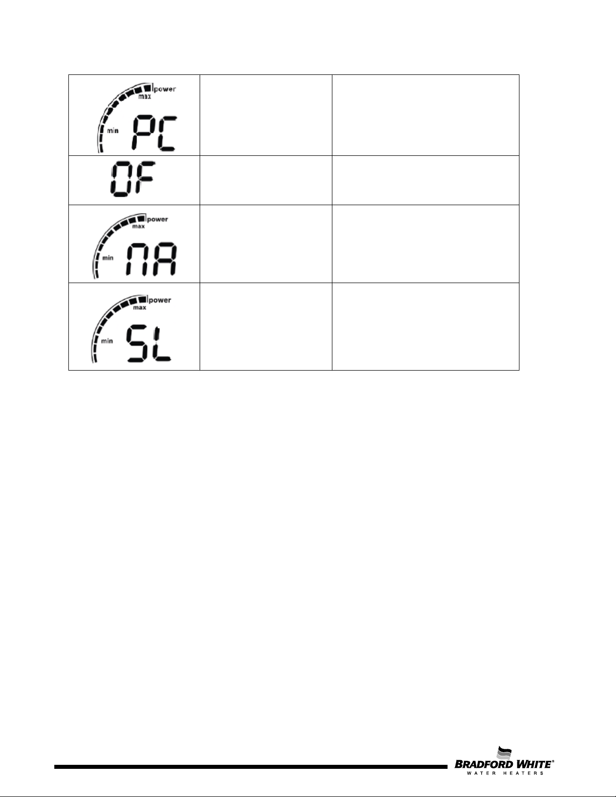
SL
Temperature Limit
PE
Appliance Type
PF
Bypass
PA
Actuator Calibration
IC
ICC
E
Exit
P0
L2 Gas Adjust
P1
Maximum Power
P2
Minimum Power
UC
Automatic Calibration
P3
Powerbus Address
Control Panel Sub-Menus:
To access the sub-menus, simultaneously press the P, Up, and Down buttons for 3 seconds. The
display should default to displaying P4. The available sub-menus are:
Table 6 – LCD Sub-Menus
To navigate the sub menus, press the Up or Down buttons. To enter a sub menu, press the P button. If
you would like to exit a sub menu, or the menu all together, navigate the Up or Down buttons until the
display shows E. Press the P button to Exit back to the previous menu, or back to the main display. Holding
the P button for 3 seconds or more will confirm a change. The display will blink while a change is being
saved.
Page 13
13
Page 14
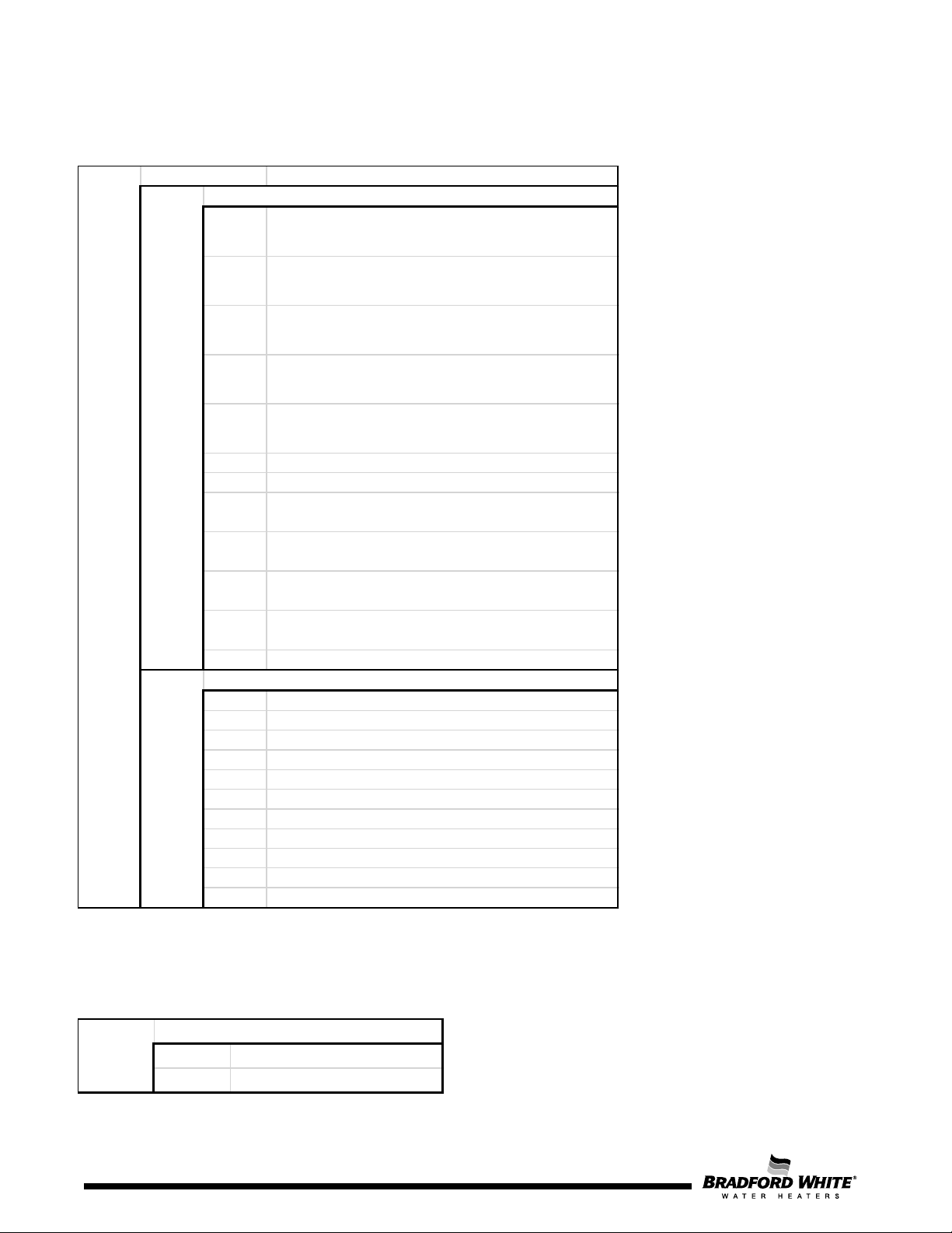
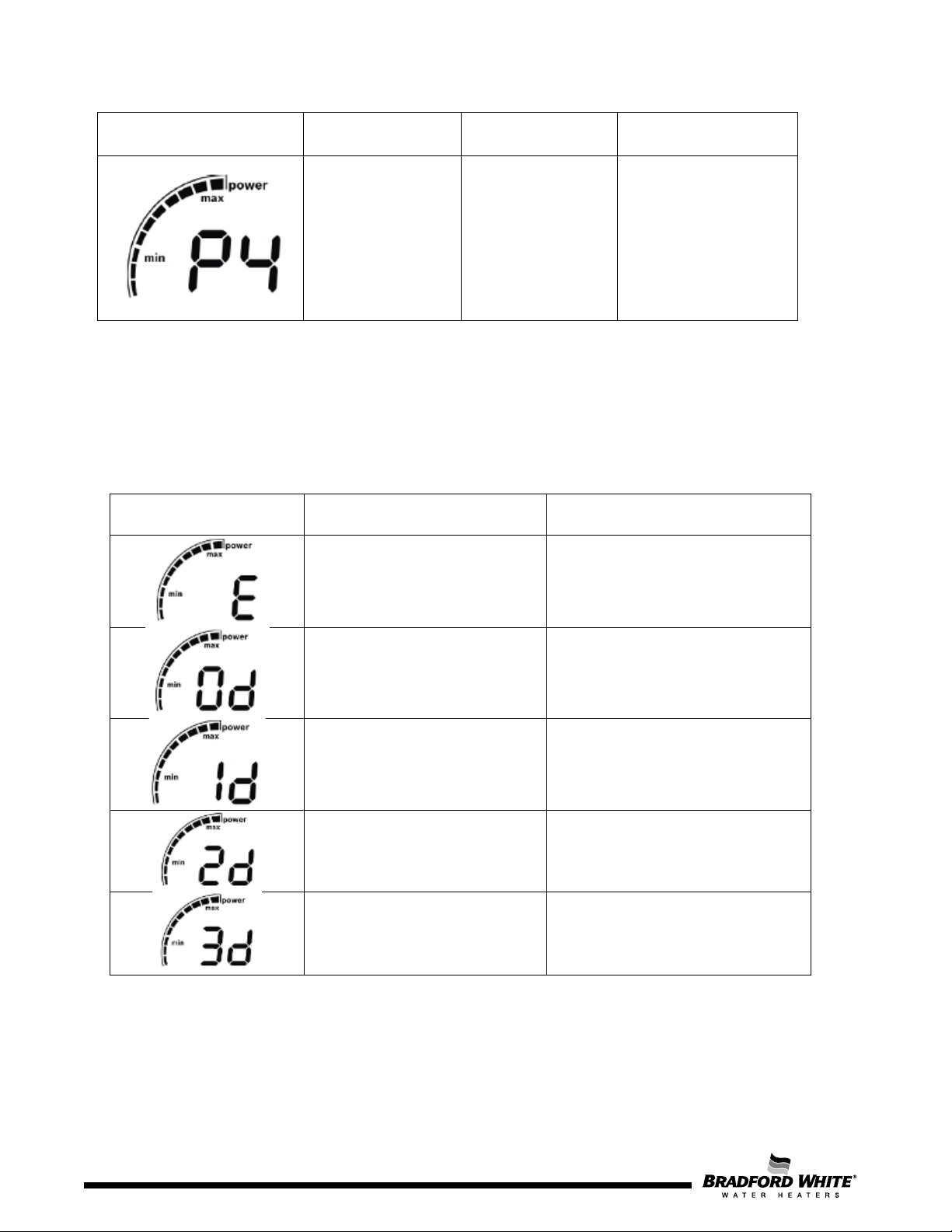
P4 - Information
0d
Chamber NTC - Water Temperature at exit of heat
exchanger
1d
Inlet NTC - Current temperature of the temperature
sensor of the water inlet pipe
2d
Outlet NTC - Current temperature of the temperature
sensor of the water outlet pipe
3d
Flow - Total water flow through the unit. Includes flow
through both the main and bypass valves
4d
Barometric Pressure - Current barometric pressure at
installation location
5d
Fan Speed - Current fan speed (Hz.)
6d
Output Power - Current burner power %
7d
SS Hex NTC - Temperature sensor of the flue gases
between the Primary and Secondary Heat Exchanger
8d
Exhaust Gas NTC - Temperature sensor of the flue gases
at the exhaust
9d
Ambient NTC - Current temperature inside the cabinet.
Sensor is located near the fan.
10d
External Tank - Current temperature on the external tank
(if connected)
E
Exit - (Return to P4 menu)
1F
First most recent error code
2F
Second most recent error code
3F
Third most recent error code
4F
Fourth most recent error code
5F
Fifth most recent error code
6F
Sixth most recent error code
7F
Seventh most recent error code
8F
Eighth most recent error code
9F
Ninth most recent error code
10F
Tenth most recent error code
E
Exit - (Return to P4 menu)
OD - Operation Data
FH - Failure History
P4
OD
FH
P7 - Gas Type
nA Natural Gas (NG)
LP Liquid Petroleum Gas (LPG)
P7
P4 – Information Menu: Displays informational data regarding the unit. This submenu can be useful for
diagnosing the appliance, as needed.
P7 – Gas Type Menu: This menu allows selection of the gas type for the appliance. Improper gas type will
affect appliance performance and can lead to unsafe operating conditions. To change the gas type, press
the Up and Down buttons to the correct gas type. Press the P button to set the appliance to the specific
gas type. See the Manifold section for more information on gas type conversion.
14
Page 15
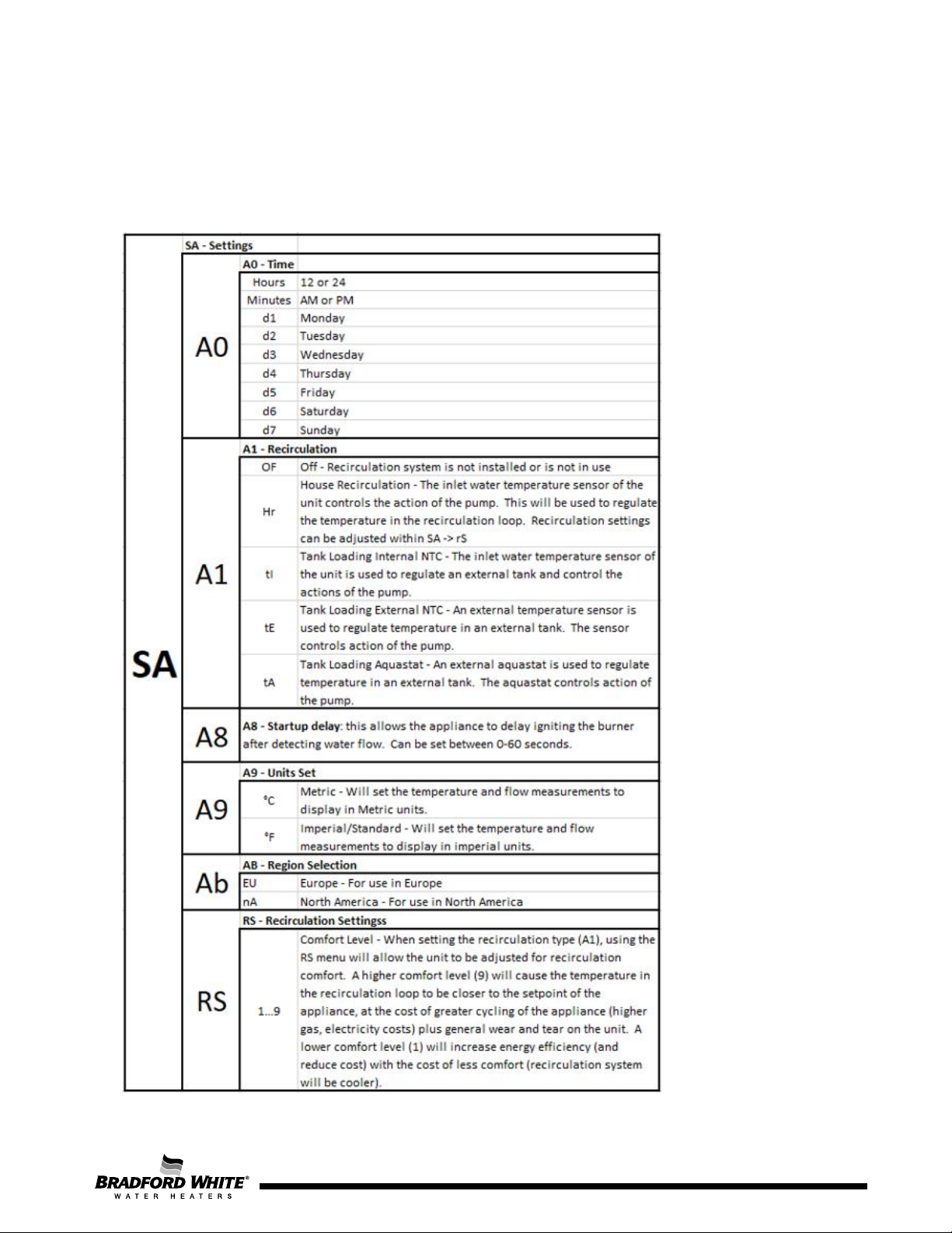
P9 – Purge: This menu allows the blower to run, purging the exhaust venting. To engage this function,
use the Up and Down buttons to select P9. Within 2-5 seconds, the fan should begin working. To exit this
function, use the Up and Down buttons to move to a different menu.
SA – Settings: This menu allows several different settings for the appliance to be changed, such as
recirculation loop, units (°F/°C), etc. A summary of menu options is as follows:
Page 15
15
Page 16
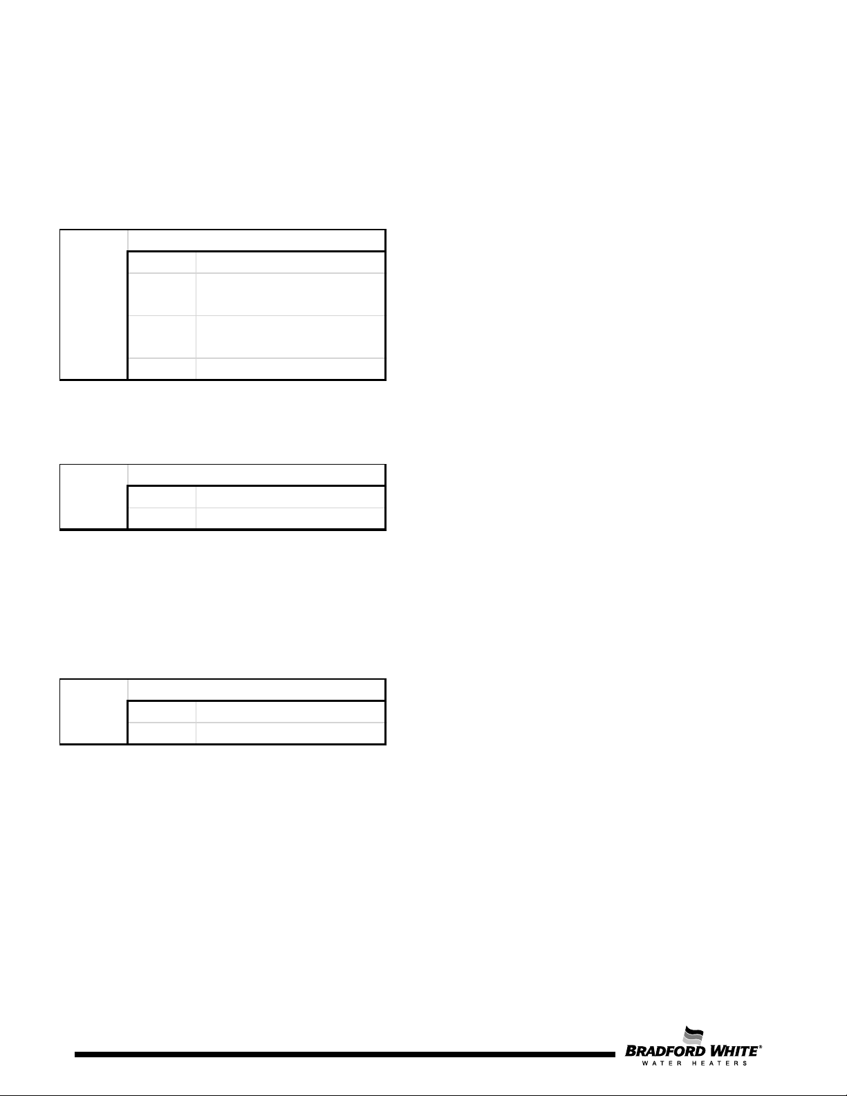
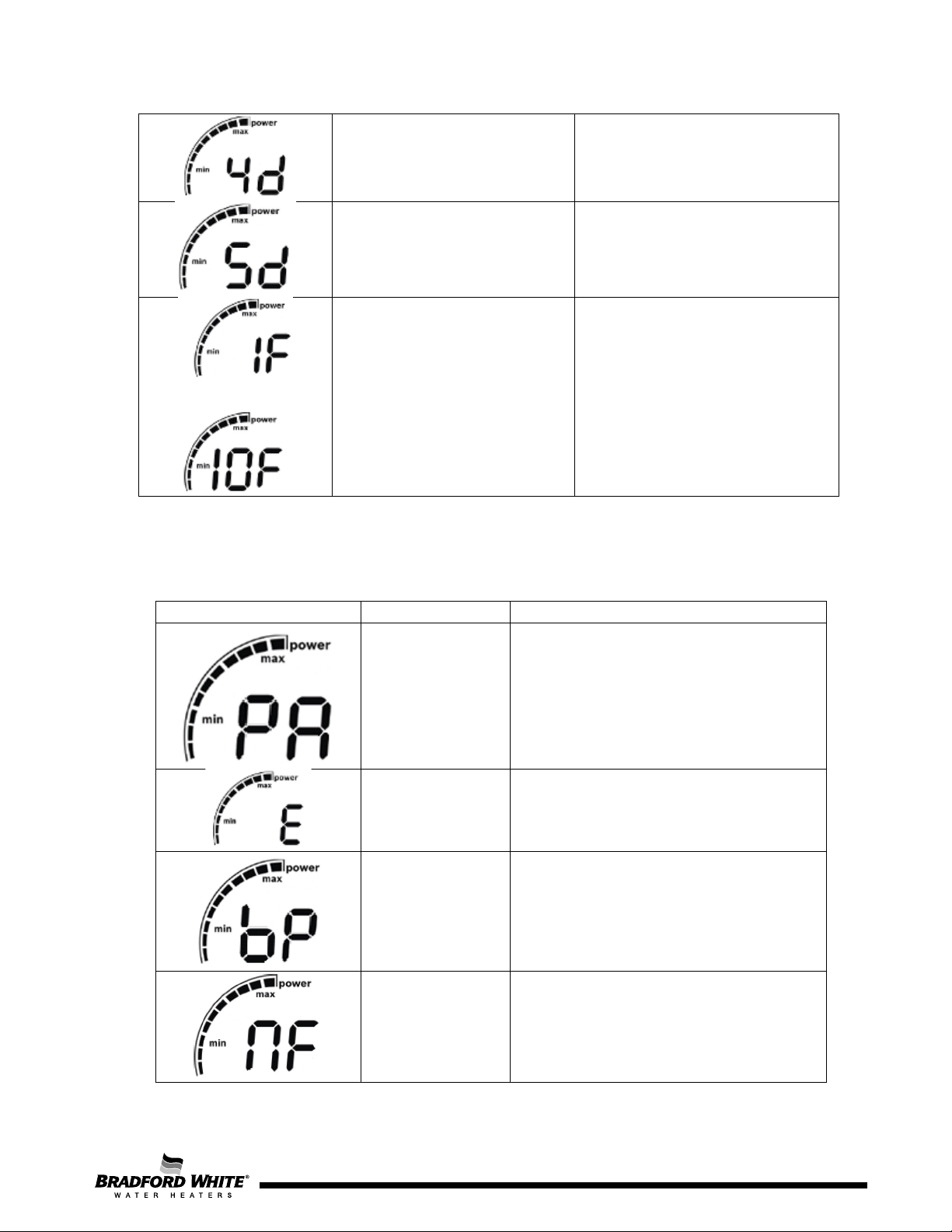
PE - Appliance Type
TP Appliance Type
AP
Appliance Power ( 160/199)
kBtu
nO
Appliance model (IN/OU:
indoor/outdoor)
E Exit
PE
PF - Bypass Activation
EN Enable
DI Disable
PF
PA - Actuator Calibration
bP Bypass Actuator Calibration
nF Main Water Actuator Cal.
PA
LM – Temperature Limit: This setting allows the maximum setpoint limit of the appliance to be set. The
maximum temperature for a residential model is 140 °F. To change the limit, access the SL menu, and set
the desired limit with the Up and Down buttons. You can also turn off the limit by selecting OF (off) in the
limit menu. Pressing the P button for 3 seconds will save the changes.
PE – Appliance Type: This menu allows changes to several options, including: appliance type, power, and
model. After initial setup, this menu should not be accessed.
PF – Bypass Activation: This menu allows the main bypass valve to be activated or deactivated. Normal
state is for this valve to be activated: allowing the bypass valve to function will let the appliance maintain
better temperature stability and overall optimized performance.
PA – Actuator Calibration: This menu controls access to the calibration of the two water valves. The main
valve controls overall water flow to the appliance: if water flow exceeds the heating capacity of the
appliance, the main valve will restrict water flow to allow the appliance to maintain temperature setpoint.
The Bypass valve allows colder inlet water to be blended with water from the heat exchanger, to create a
consistent outlet water temperature. Both calibrations require water to be flowing before beginning the
calibrations. Further details on the process of the calibrations can be found in this manual or the
Installation/Operation Manual.
IC – Ionization Correction: This menu controls the parameter for the ionization correction model. The
ionization control model is an auxiliary method for the appliance to determine air flow during operation.
Using this parameter allows greater reliability in operation. There are two different options for IC: on or off.
Default is on; there are no real applications where it would be beneficial for IC to be turned off. Ionization
control is a menu option in the P1 menu (see P1 menu table below); here it is default-set to off. Because
P1 is a manual calibration, it is best operating procedure to again leave the default setting.
E – Exit: This allows exiting from the main menu back to the home screen of the display. Scrolling to the
“E” option within the menu or submenu will always allow the user to move back to the previous menu.
P0 – L2 Gas Adjust: This menu allows for the verification of minimum power adjustment. There are two
different options for P0: on or off. The default setting is off. Again, it is best operating procedure to leave
the default setting.
16
Page 17
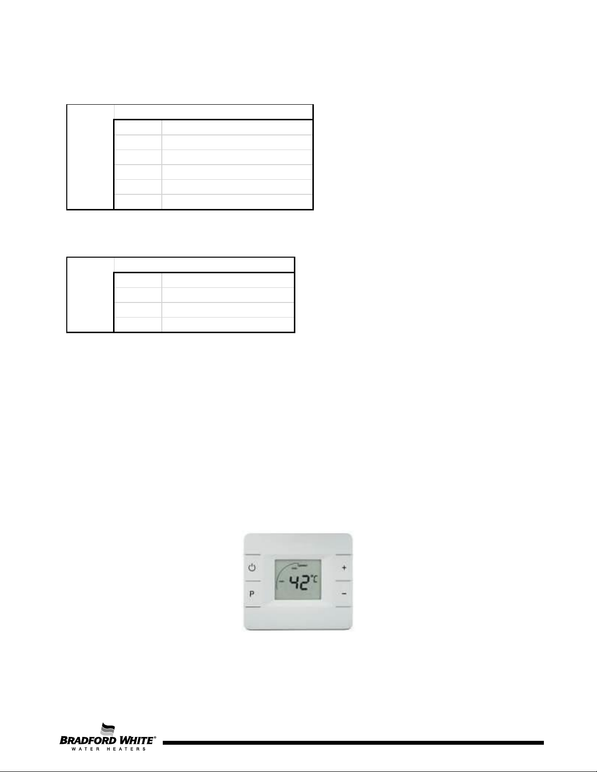
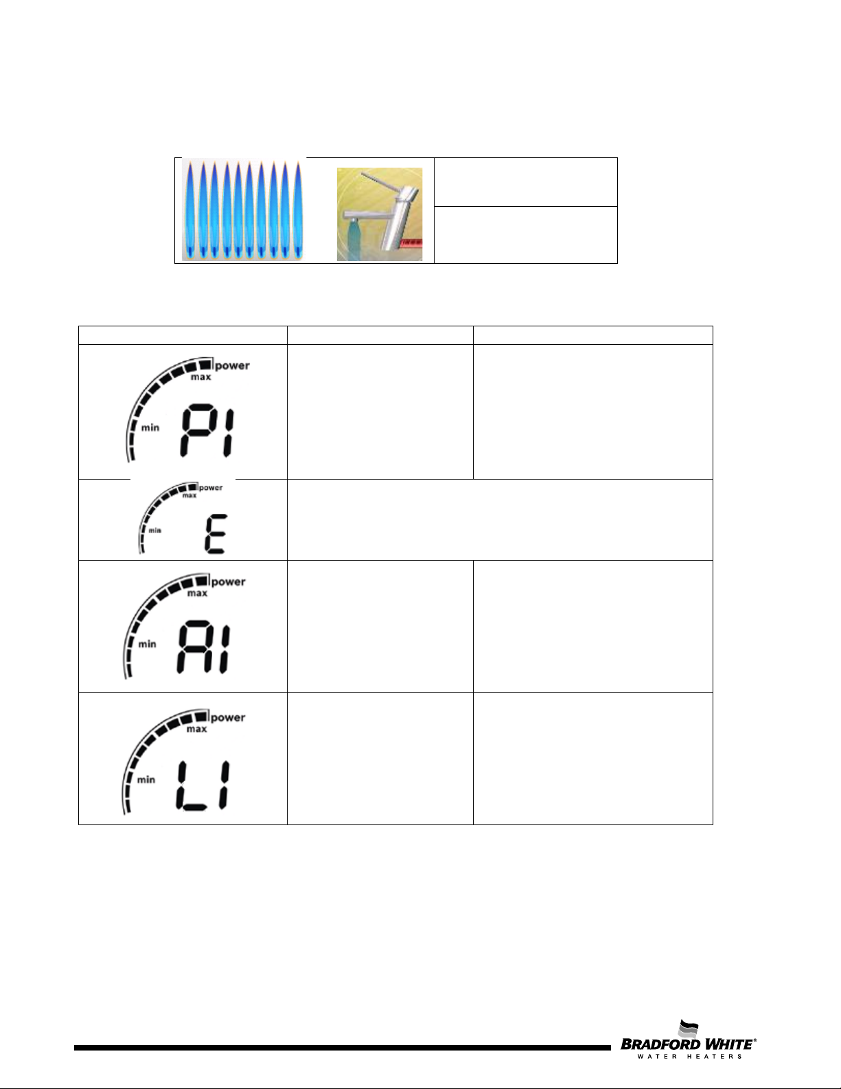
P1 - Maximum Power
A1 High Fire Air Adjustment
L1 High Fire Gas Adjustment
b1 Low Power Air Flow Calibration
rP Reset Parameters
IC Ionization Correction
E Exit
P1
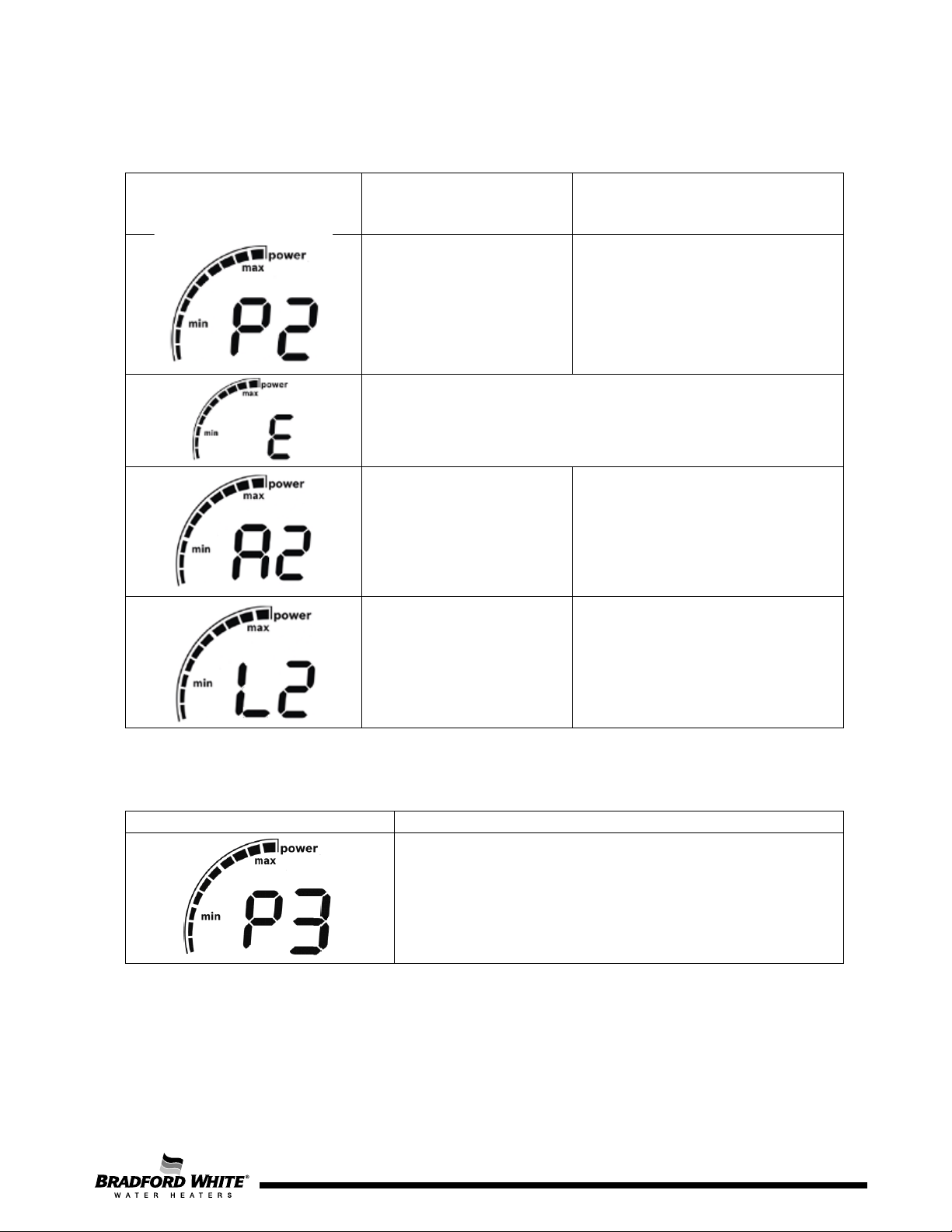
P2 - Minimum Power
A2 Low Fire Air Adjustment
L2 Low Fire Gas Adjustment
rP Reset Parameters
E Exit
P2
P1 – Maximum Power: This menu allows adjustment to the fuel/air ratio at maximum power. This is a
manual adjustment; before proceeding, read about the procedure in the Installation/Operation manual.
P2 – Minimum Power: This menu allows adjustment to the fuel/air ratio at minimum power. This is a
manual adjustment; before proceeding, read about the procedure in the Installation/Operation manual.
UC – Automatic Calibration: This menu begins the process of performing the appliance’s automatic
fuel/air ratio adjustment. After entering this menu, the display will show “01”, indicating the first step of the
adjustment. Do not perform the automatic calibration without first reading about it in the
Installation/Operation manual.
P3 – Powerbus Address: This menu allows the selection of a powerbus address for a wired remote control.
The default address is 20.
4.2 Control Panel Inbuilt (Outdoor Version)
The control panel, located inside the appliance, allows the installer or technician to perform all the
different operations needed during commissioning / diagnostic procedures, as described above in
the indoor section. The buttons and functionality of the control panel is the same between the indoor
and the outdoor models.
Figure 10 – Wired Control inside the Appliance (Outdoor Version)
17
Page 18
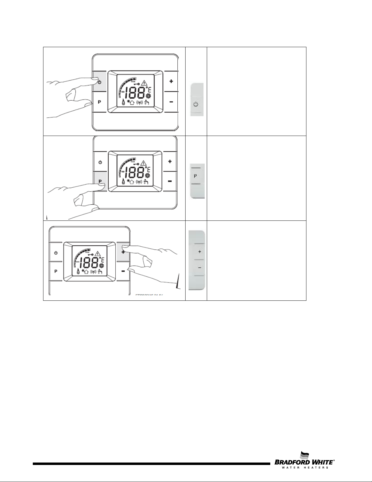
On / Off button
longer, errors are reset.
The main switch is assembled on
the PCB and disconnects the unit.
Anti-Freeze function is assured
even in the OFF position
When pressed for 3 seconds or
Program Button
Used to enter in to different
- “Enter” in service mode
- Scroll in the service mode menu
- Save value or adjust set values
- Save a temperature set (user)
Note:
services:
navigation on parameters inside
Table 7 – Control Panel Buttons
Selection button
Used to select temperature
values, adjustments and
the visualisation mode.
18
Page 18
Page 19
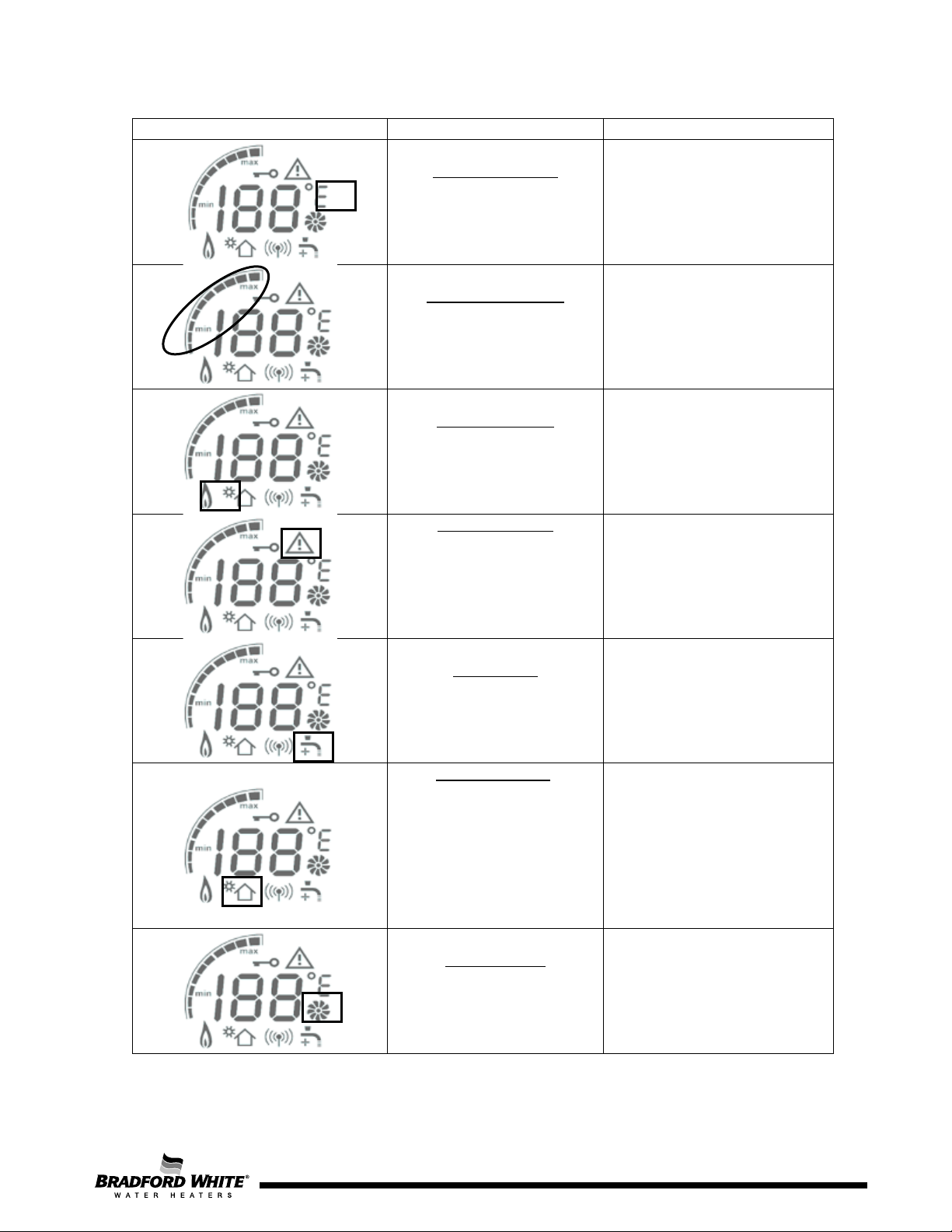
Symbol
Description
Observation
Warning symbol:
Solar application:
Temperature Unit:
ºC – default value
ºF – alternative value
Power bar indicator:
Indication of the current
operation power
Flame indication:
Indication of flame in the
burner
Combined with an error
indication / warning code
indicates a faulty
performance
Selection can be done by
changing default value on
service mode
Indicative Value (in %)
Note: each line corresponds to
10%
Symbol displayed when
ionization is detected - flame
presence
Tap symbol:
Indication of not enough
power to reach set point
Indication that the automatic
solar function is activated,
meaning that the appliance
is receiving pre-heated inlet
water, with no need for
In case symbol is displayed,
decrease (-) or increase (+)
flow accordingly
The symbol is displayed and
burner is shutdown when T in
is under following conditions:
T
≥ T
in
set
– 1K
burner to start
Fan operation:
Indication that the fan is in
operation
Table 8 – Display Symbols
Page 19
19
Page 20
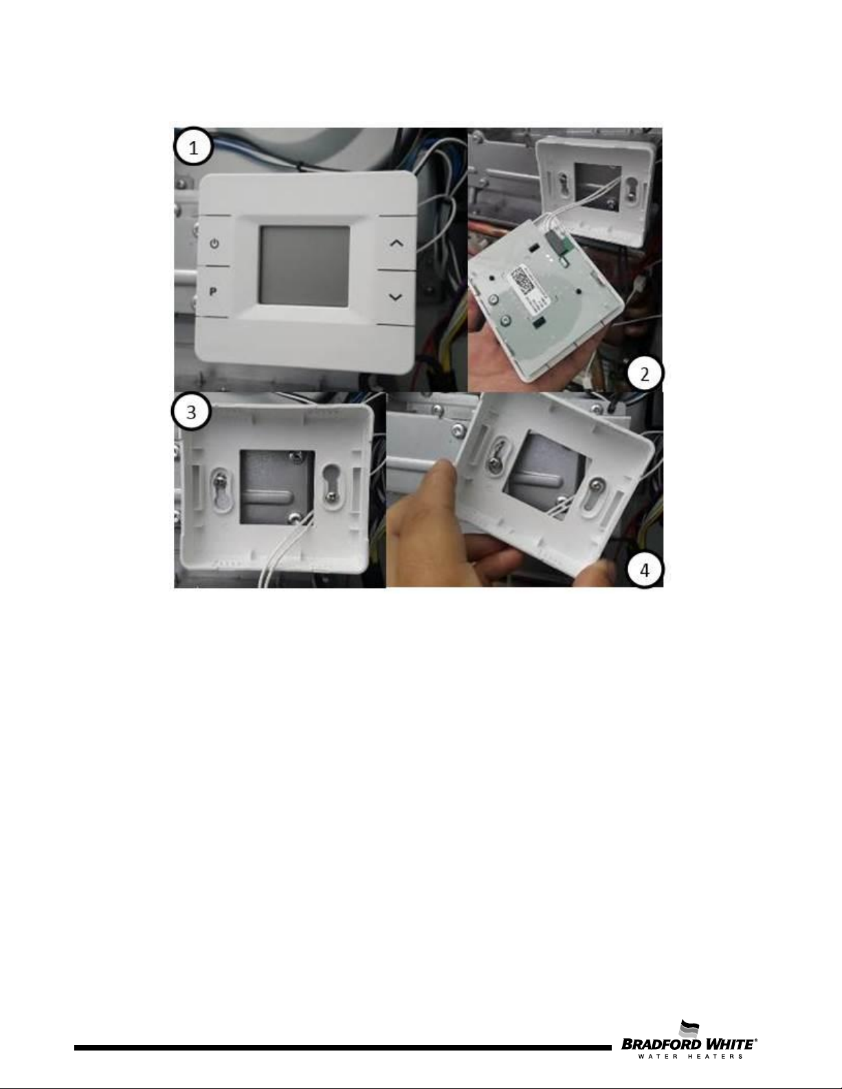
20
Figure 11 – Disassembling the Control Panel for Installer
To disassemble this HMI, the necessary steps are the following:
1. Pull the HMI (Remember that a cable is still connected.
2. Disconnect the cable.
3. Loosen the 2 screws.
4. Rotate the base of the HMI and pull it.
5. Remove the support of the HMI.
20
Page
Page 21
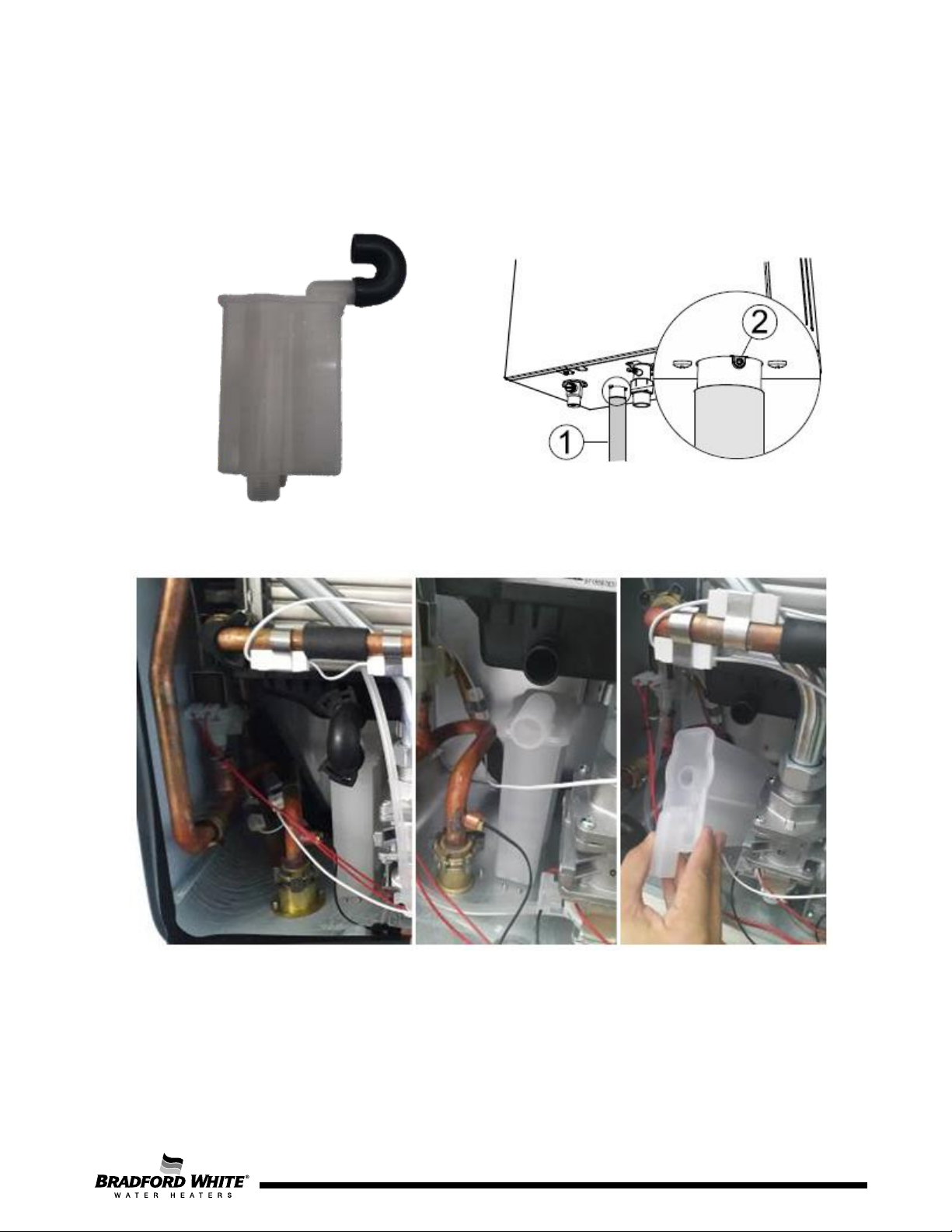
4.3 Condensate Siphon
The appliance includes a condensate siphon which stores condensate generated during operation from
the condensate collector below the stainless-steel condensing heat exchanger. The siphon must also
connect to an adequate PVC drainage pipe (1) to drain the acidic condensate once full. As this unit is a
high-efficiency appliance, condensate flow can be as high as 2 gallons per hour at full power.
Figure 12 – Condensate Siphon
Figure 13 – Disassembling the Condensate Siphon from the Unit
To disassemble the siphon from the metal box and heat cell the necessary steps are the following:
1. Pull the tube between the siphon and the condensate collector.
2. Remove the screws on the bottom of the appliance.
3. Pull the siphon out.
Page 21
21
Page 22
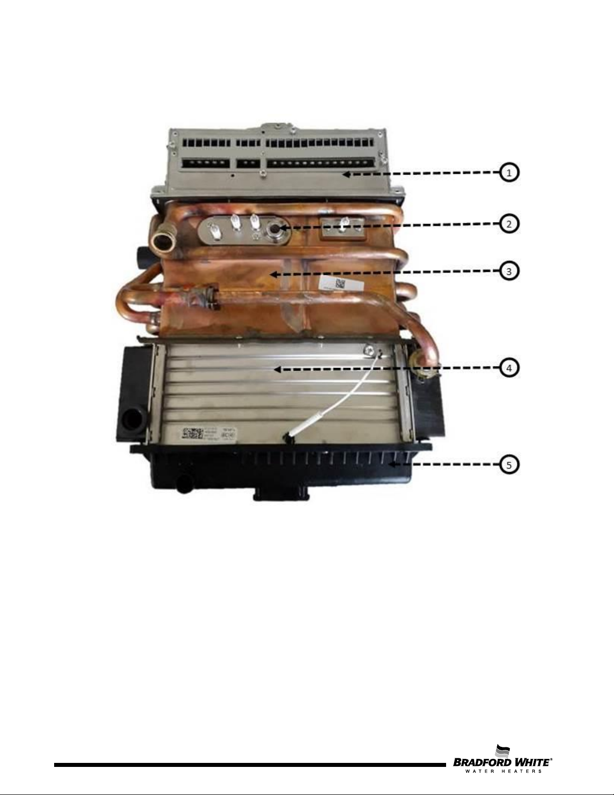
1 – Burner
4 – Stainless Steel Condensing unit
2 –
5 –
3 – Copper Heat exchanger
4.4 Heat Cell
The heat cell includes a heat exchanger with flame sight window, ignition and ionization electrodes,
condensing unit, and condensate collector.
To disassemble the heat cell from the metal box the necessary steps are the following:
1. Remove the condensate collector (2 screws)
2. Remove the control unit (2 screws and cables)
3. Loosen the gas tube on the manifold
4. Remove the 4 screws from the gas valve
5. Remove the clips between the heat cell and all the water tubes.
a. Cold water tube from the condensing unit
b. Hot water tube from the heat exchanger
22
Electrodes
Condensate collector
Figure 14 – Heat Cell
Page 22
Page 23
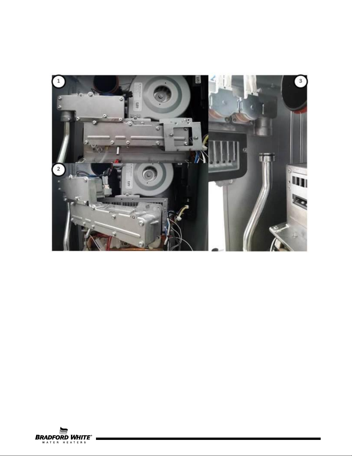
4.5 Gas Manifold
The gas manifold is a gas distribution pipe with integrated drilled injectors.
Figure 15 – Disassembling the manifold from the heat cell
To disassemble the manifold from the burner the necessary steps are the following:
1. Remove the fan
2. Disconnect the solenoids from the top left of the manifold
3. Disconnect the segmentation safety valves
4. Remove the HMI for installer (see figure 13). In the first picture the HMI is already removed
except its base.
5. Remove 4 screws from the manifold to separate it from the burner.
6. Loosen the screw from the gas tube.
7. Rotate and push up the manifold at the same time to remove it from the appliance
To assure a wide modulation range for the appliance, the manifold cover allows the gas supply to be
utilized across 3 different segments.
Page 23
23
Page 24
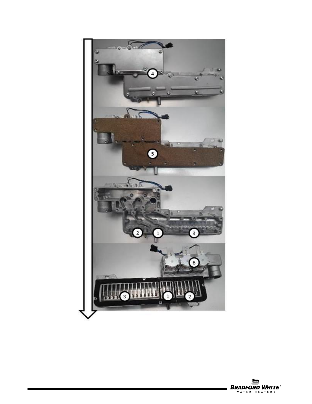
1 – Burner segment 1
4 – Gas restrictor seal
2 – Burner segment 2
5 – Gas seal
3 – Burner segment 3
6 – Segmentation safety valves
24
Figure 16 – Disassembling the Manifold
Page 24
Page 25
As shown in the previous figure, the manifold contains 3 solenoids valves (SV) that are responsible
for the release of gas in each burner segment. This allows the unit to have 6 burner level stages
according to the solenoid combination:
Stage 1 – SV 1
Stage 2 – SV 2
Stage 3 – SV1 + SV2
Stage 4 – SV3
Stage 5 – SV1 + SV3
Stage 6 – SV1 + SV2 + SV3
The manifold is only available as one spare part. However, for maintenance purposes it may be
required to open the manifold. The Gas Seal is made of cork and is not available as an individual
spare part.
For maintenance purposes the process of disassembling the manifold has the following steps:
1. The manifold is already separated from the appliance. If not, follow the steps in Figure 15.
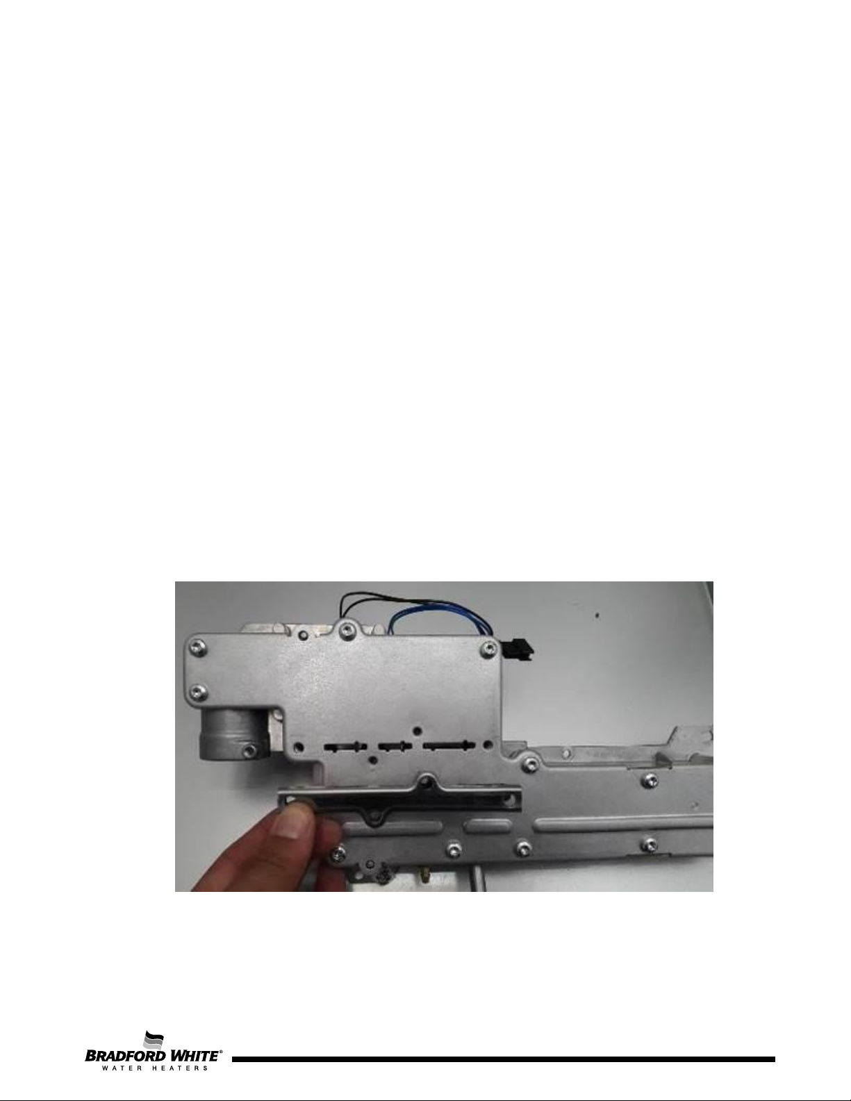
2. Remove the gas restrictor seal (4 screws) (see figure below)
3. Remove the front cover (12 screws)
4. Remove the cork seal
5. Remove the rubber seal from the reverse side of the manifold. Every time that the manifold
is disassembled, this seal must be replaced.
The new manifold allows the installer or technician to easily convert the appliance between natural
gas (NG) and Liquid Propane Gas (LPG). The appliance comes factory installed in NG configuration,
so if the unit is being used in a NG application, no additional modification is necessary. To operate
the unit with LPG, a gas restrictor must be installed, as detailed in the following figures.
Figure 17 – Gas Restrictor Seal on the manifold (unit set up for natural gas operation)
Page 25
25
Page 26
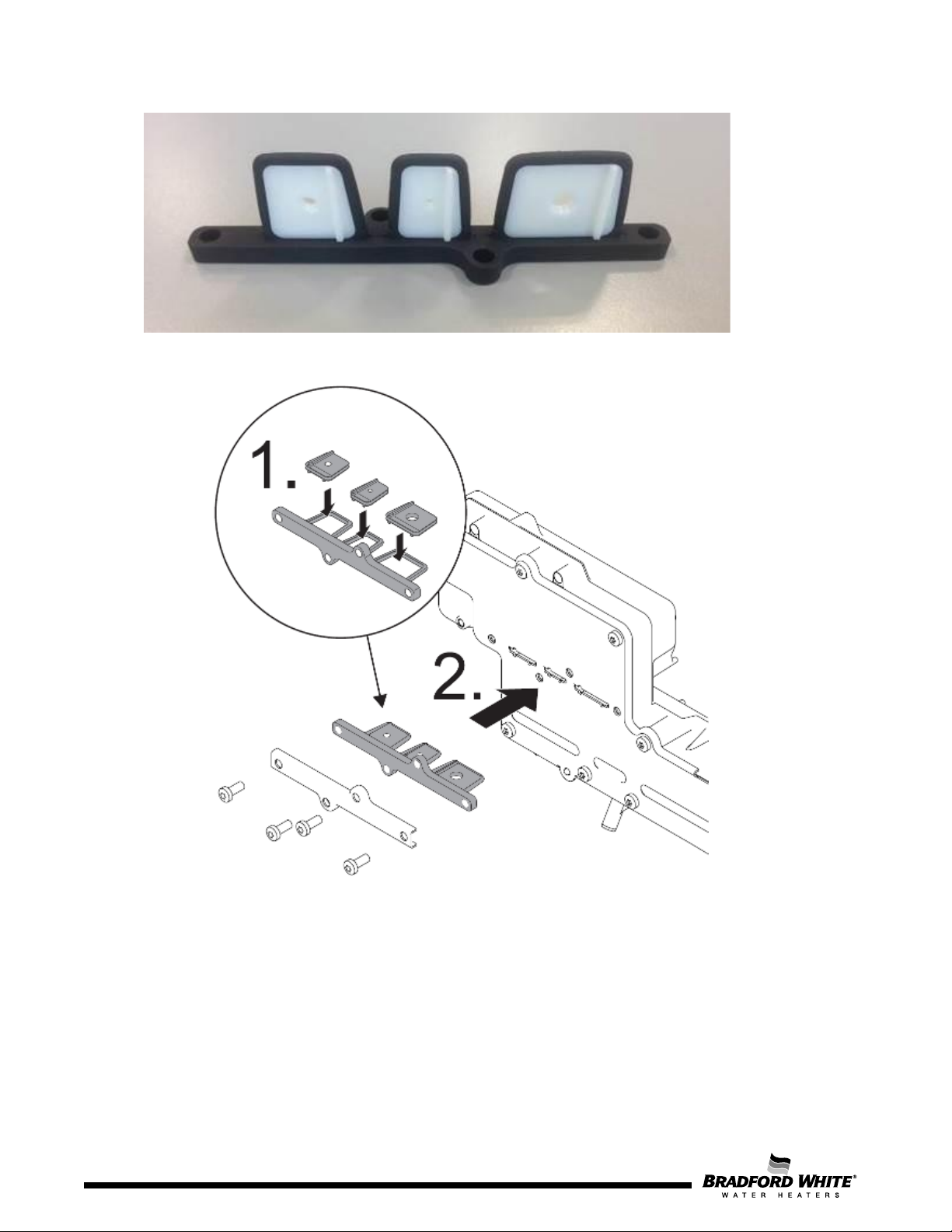
Figure 18 – Gas Restrictor Diaphragm for Propane Operation
Figure 19 – Gas Conversion Procedure for LPG Operation
For gas restrictor conversion, the manifold doesn’t need to be disassembled. The steps for restrictor
conversion are:
1. Disassemble the gas restrictor seal by removing the 4 screws.
2. If the appliance is working with NG, there is no restrictor inside. If the appliance is working with
LPG, there is a rubber diaphragm with 3 restrictors.
3. Remove the diaphragm if the objective is to convert the appliance from LPG to NG or install the
diaphragm if the objective is to make the conversion from NG to LPG.
26
Page 26
Page 27
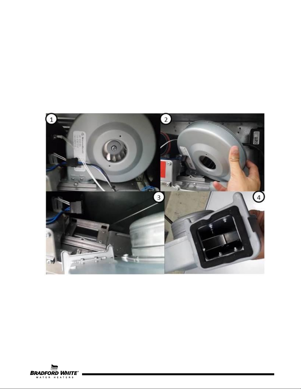
4.6 Fan
The control unit monitors the primary air flow to the burner by varying the fan motor power supply
voltage (DC), ensuring a correct variable speed according to the output needed.
The fan motor provides an additional control signal to enable/disable operation and the speed of
the fan is measured by the feedback signal provided by the fan’s motor. The signal consists of a
square wave with a frequency proportional to the speed of the fan.
Additionally, this system allows the appliance to detect the size of the installed vent pipes and
adapt the fan to the exhaust needs.
Figure 20 – Disassembling the Fan
Disassembly of the fan does not require removing the control unit. The steps for fan removal are:
1. Disconnect the gas sensor.
2. Disconnect the segmentation safety valves.
3. Remove the front screw.
4. Remove the fan paying attention to the fan base (the fan is trapped on the back).
Page 27
27
Page 28
Page 28
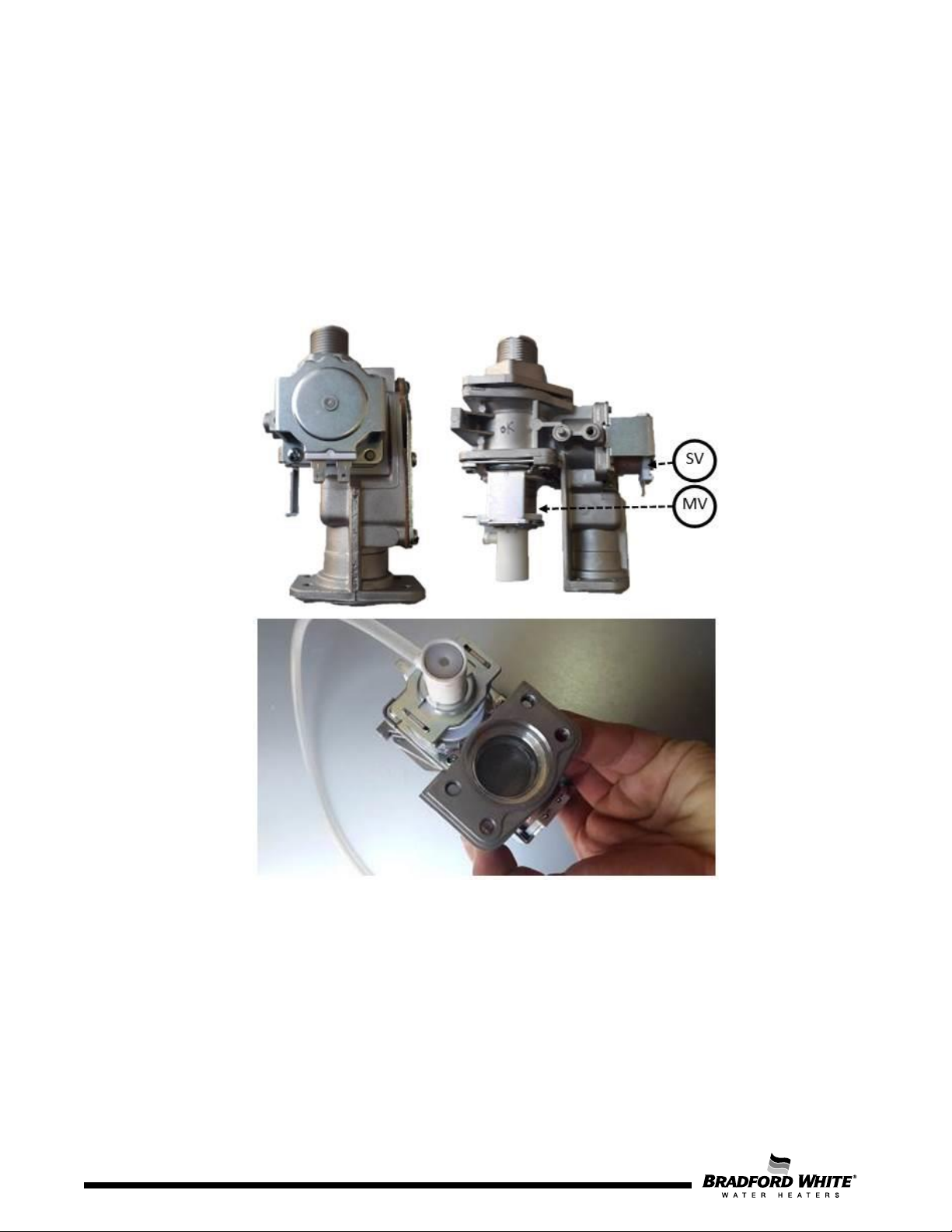
4.7 Gas Valve
It is possible to control gas flow to the burner by the modulating gas valve (MV) in addition to the
control unit. The gas valve is composed of an additional solenoid identified as safety valve (SV1)
releasing the modulated gas to and from the solenoid gas valve.
Safety Solenoid Valve
The safety valve (SV) is the first safety element that releases gas to the burner. The second safety
level elements are the solenoid valves in the gas manifold of the burner. They release gas to the
first, second, and third burner segments, respectively, acting as safety and segmentation valves.
Figure 21 – Gas Valve View
Modulating Valve
Mechanical modulated valve
The gas flow (thermal load) is automatically modulated to ensure the correct outlet water
temperature, even under water flow or inlet temperature variations.
To disassemble the gas valve, the necessary steps are the following:
1. Release the nut on the gas tube.
2. Remove the 4 screws on the buttons of the appliance.
28
Page 29
29
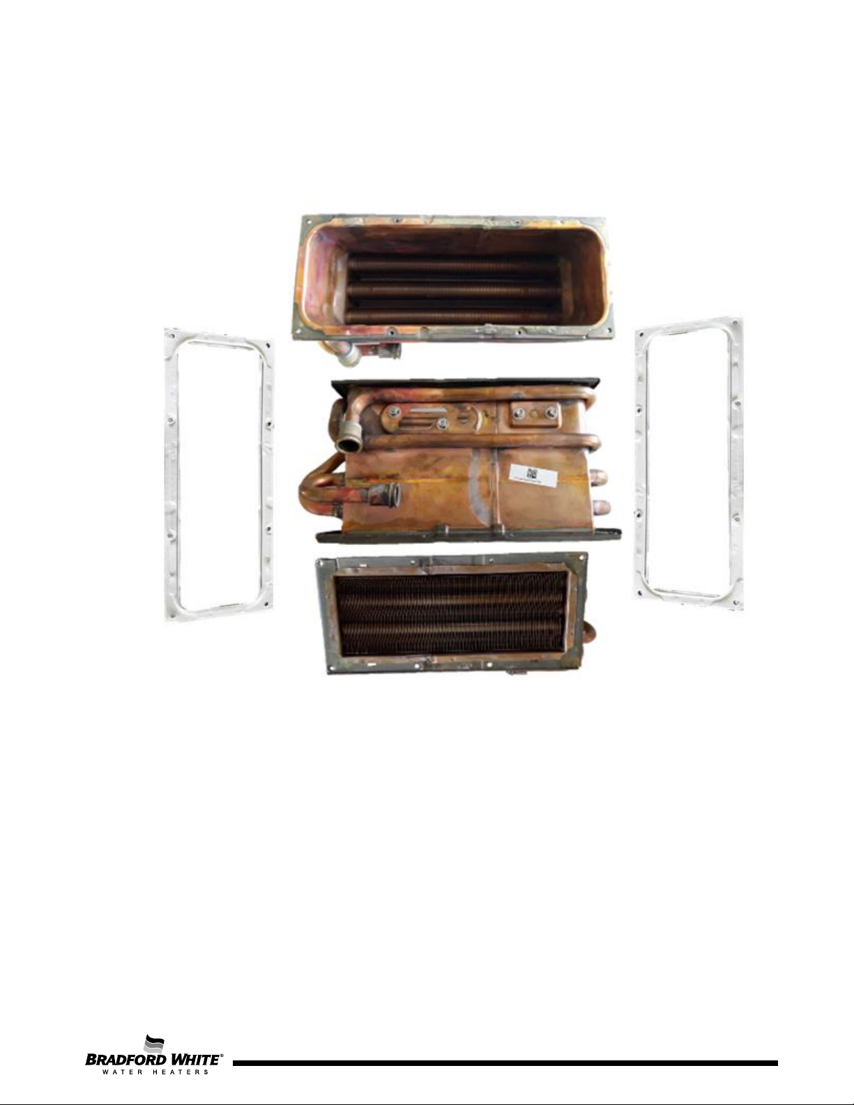
4.8 Heat Exchanger
The copper heat exchanger has different size and fin amounts according to the appliance model (160
or 199). This configuration ensures the sealed heat transfer from the flame heat to the water that
flows through the copper pipes.
Figure 22 – Heat exchanger
To disassemble the heat exchanger from the entire heat cell the necessary steps are the following:
1. Disassemble the heat cell from the appliance (See Section 4.4)
2. Remove burner (8 screws). Remove condensing unit (8 screws).
3. The seals must be always replaced when the heat exchanger is disassembled.
Page
29
Page 30
Flow (g/min)
7.13
6.34
4.75
3.69
2.64
2.11
1.05
0.52
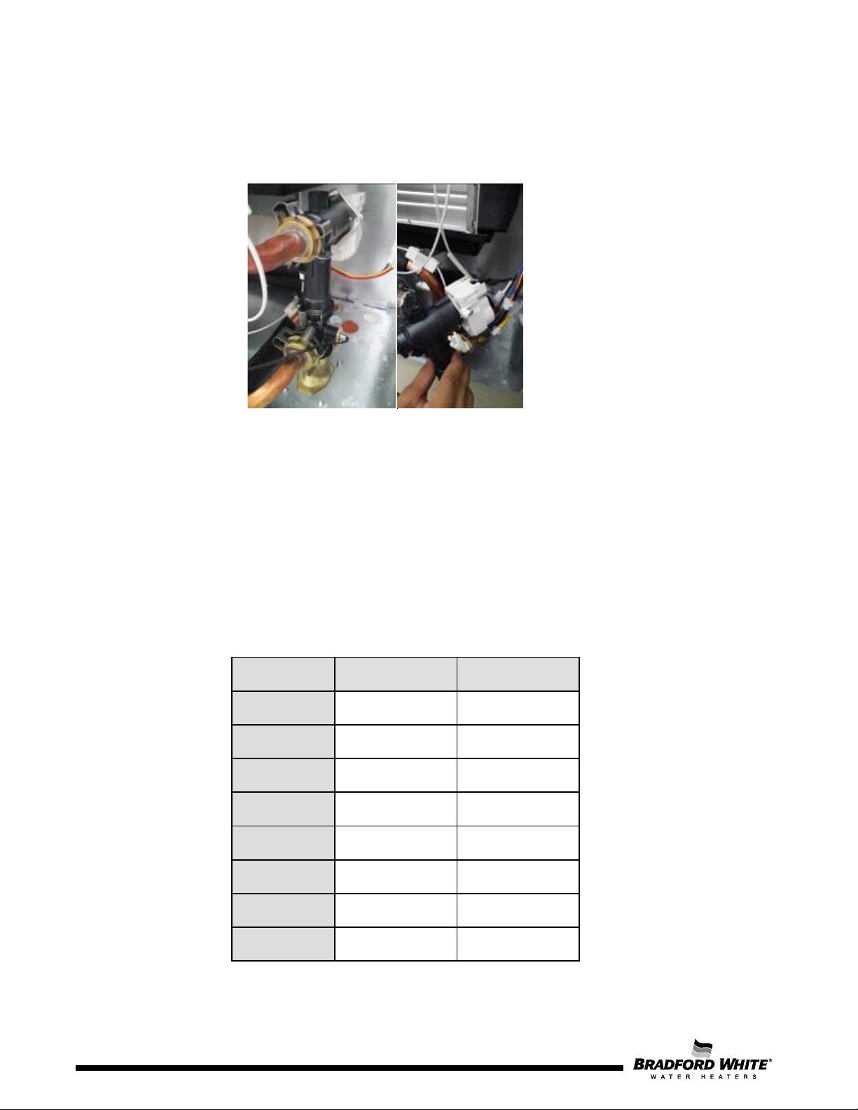
4.9 Water Valve
The inlet water valve contains the flow sensor responsible for the flow rate detection and a motor
stepper responsible for the maximum water flow control through the unit.
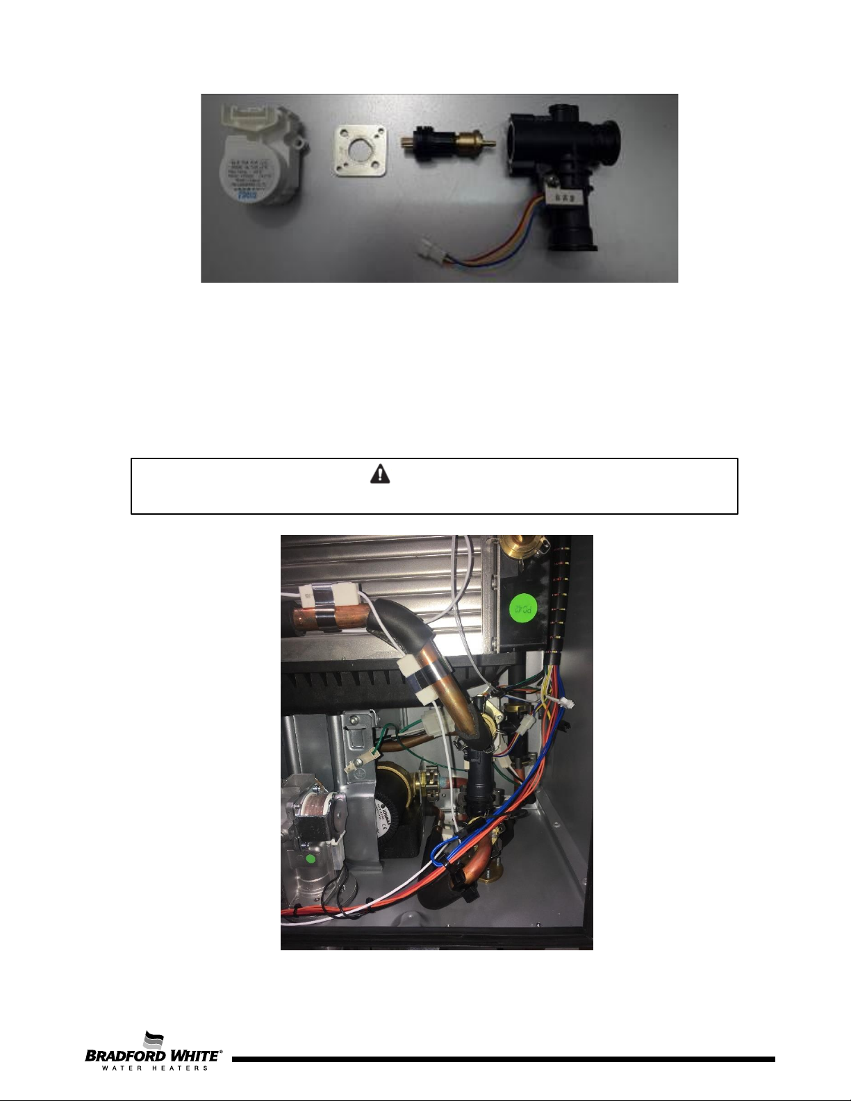
Figure 23 – Inlet Water Valve
Water flow is measured by a turbine flow sensor that is fed by a DC signal and gives a feedback
signal proportional to the measured water flow (see Table 9).
• Minimum Flow rate to start up the appliance: 0.45 gpm (1.7 l/min)
• Flow rate to shut off the appliance: < 0.5 gpm (1.8 l/min)
In case Q > min start up flow following P
• If Pout > Minimum Power, the appliance will run with the calculated minimum water flow, in order
to reach the set point with a temperature stability of +/- 2ºF (+ / - 1ºC);
• If P out < Minimum Power, the T out is assured by a pulsating burner mode + cold water mixing
(easy minimum).
Flow [l/min]
27
24
18
14
10
8
4
2
Table 9 – Water Flow Sensor Values
verification occurs:
out
Frequency [Hz]
108
96
72
56
40
32
16
8
30
Page 30
Page 31
WARNING
Figure 24 – Inlet Water Valve Composed by a Motor Stepper (left) and a Flow Sensor (right)
In order to disassemble the water valve, it is necessary to remove the clips attaching the valve to the
water piping. Note that the motor stepper and the flow sensor are one only spare part. However, for
maintenance purposes it may be required to open the water valve.
4.10 Circulation Pump (L-Series only)
The circulation pump is responsible for recovering the home re-circulation loop to minimize wasted water
and increase user comfort.
Before performing any service, ensure the power is disconnected from the appliance.
Figure 24 – Circulation Pump
Page 31
31
Page 32
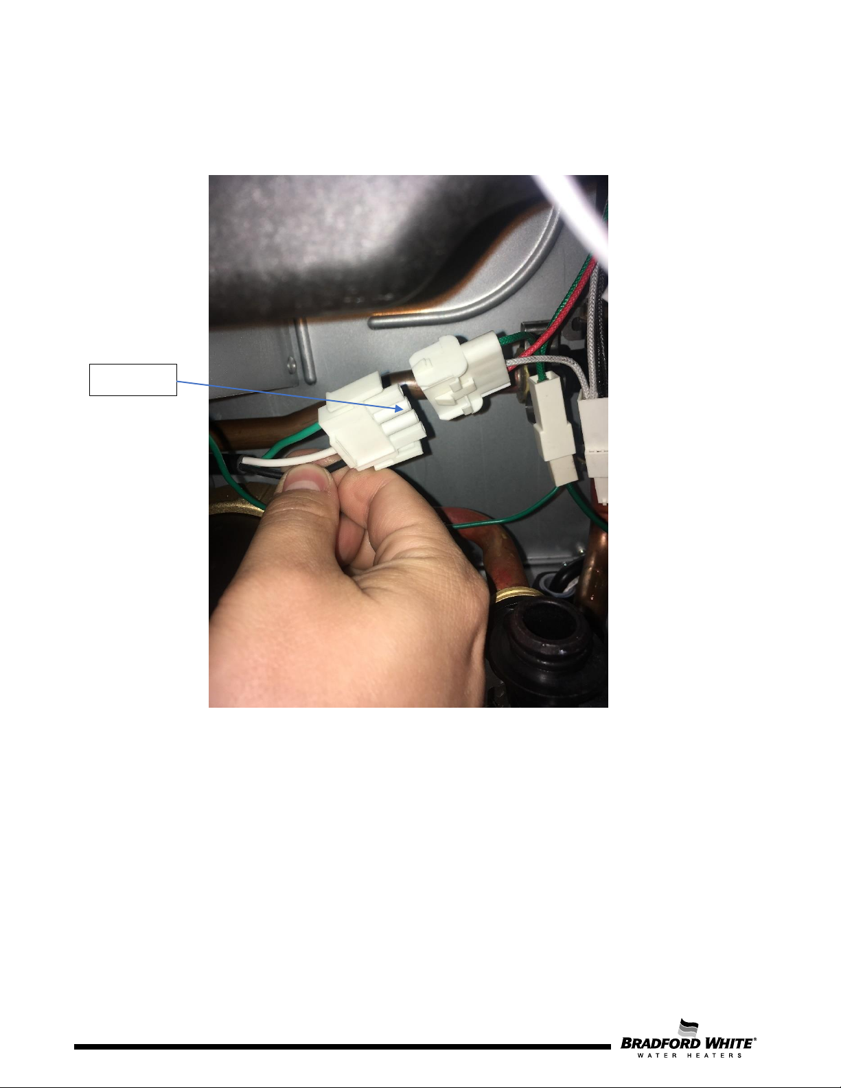
Disconnect
Removing Circulation Pump for Servicing
1. Remove the Water Valve prior to pump service (refer to Section 4.8). Once the Water Valve has
been removed, disconnect the pump harness.
Figure 26 – Step 1: Disconnect Wire Harness
32
Page 32
Page 33
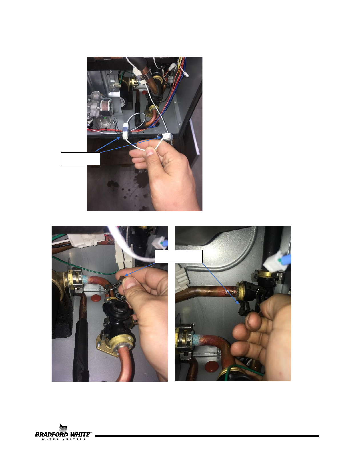
Figure 26 – Step 2: Unclip Anti-Freeze
Resistors
Figure 27– Step 3: Remove the clips holding in the pump outlet and inlet pipes.
Unclip Both
Remove Clips
2. Remove clips holding the anti-freeze resistors, then remove the anti-freeze heaters from the
water pipes as shown below.
3. Remove the clips holding in the pump outlet and inlet pipes.
Page 33
33
Page 34
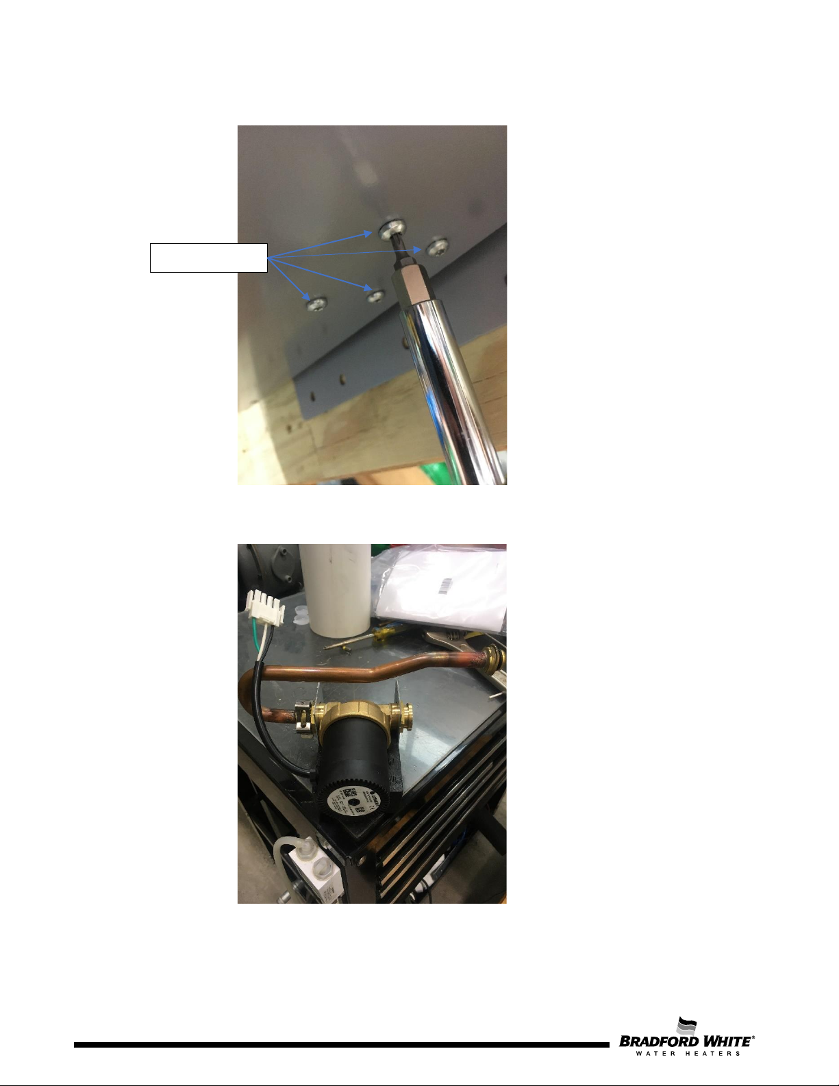
Remove Screws
4. Using a T20 Torx driver, remove the 4 screws holding the pump bracket.
Figure 28– Step 3: Remove 4 Screws
5. Finish disconnecting the pump inlet pipe and remove the circulation pump from the cabinet.
6. Service circulation pump as necessary. Reverse Steps 1-5 to reassemble circulation pump once
servicing is complete.
34
Page 34
Page 35
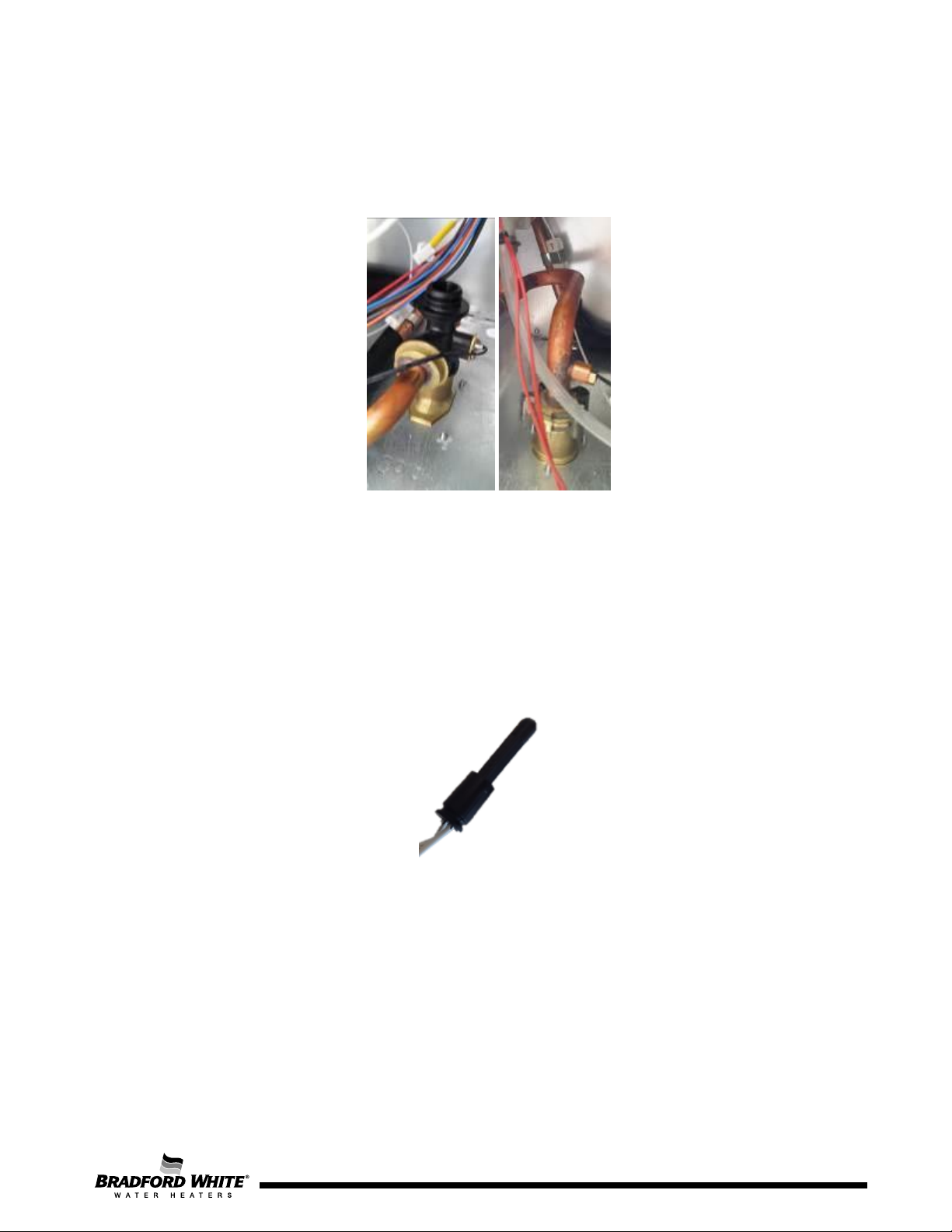
4.11 Water Temperature Sensors
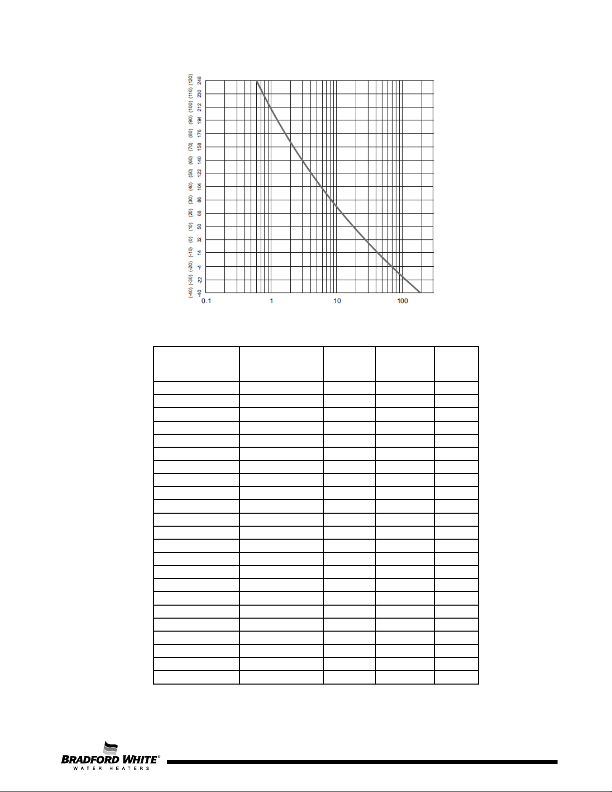
The outlet and inlet water temperature is measured by a 10kΩ NTC (See Table 13). Both NTC are
equal, but connected to different cable colors (blue wires to inlet water / red wires to outlet water).
Figure 29 – Outlet Water Temperature Sensor (left) and Inlet Water Temperature Sensor (right)
4.12 Box Temperature Sensor
The Box air temperature is measured by a 220kΩ NTC (See table 12) and is assembled on the
control unit back panel, in order to monitor the temperature inside of the sealed box.
Figure 30 – Box Air Temperature Sensor
Page 35
35
Page 36
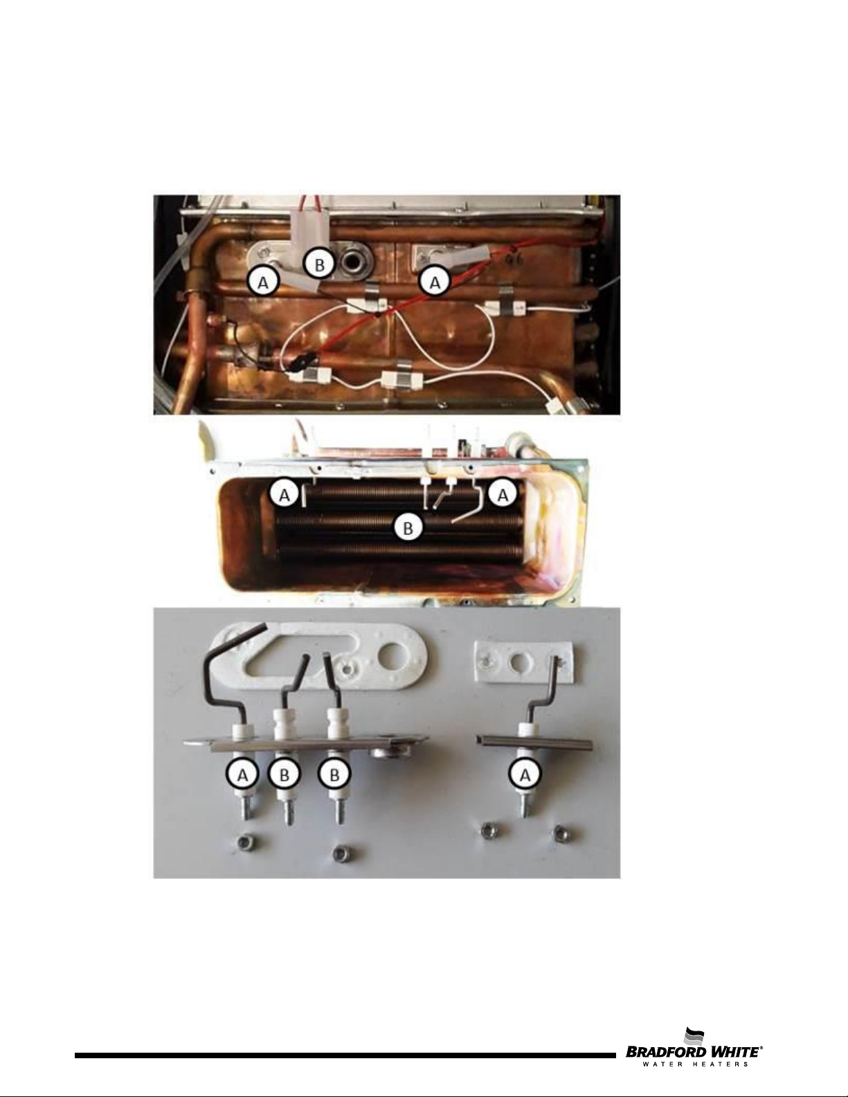
A -
Ionization electrodes
B -
Ignition electrodes
4.13 Electrodes
The spark generation is started immediately before opening the gas valve and stopped when
ionization is sensed. The flame is sensed through an ionization electrode, and detection is granted
for ionization currents greater than 0.5 micro-amps (µA).
36
Figure 31 – Electrodes Overview
Page 36
Page 37
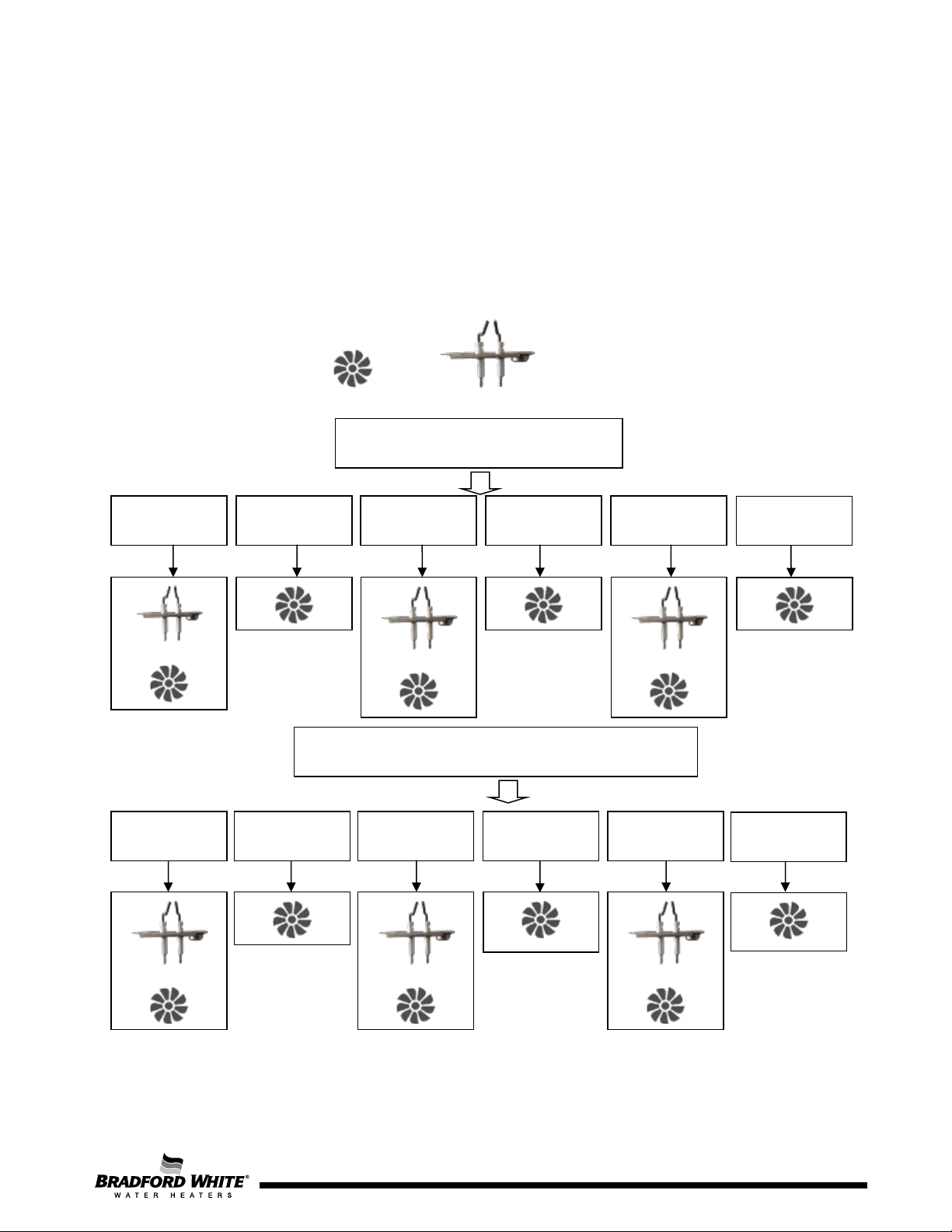
1st & 2nd Ignition Sequence
Safety Time = 23 sec
1st Attempt
(3 sec)
Purge Period
(3 sec)
2nd Attempt
(3 sec)
Purge Period
(3 sec)
3rd Attempt
(3 sec)
Post Purge
(8 sec)
3rd Ignition Sequence Safety Time of 15 sec + 30 sec
1st Attempt
(3 sec)
Purge Period
(3 sec)
2nd Attempt
(3 sec)
Purge Period
(3 sec)
3rd Attempt
(3 sec)
Post Purge
(30 sec)
Ignition Electrode
To prevent harder than necessary ignition cycles and to ensure the correct gas supply and burner stability
conditions, the following situation is verified during the safety time period.
During each ignition attempt, the system monitors the ionization signal; this signal drives the start of
normal operation. However, in the case where the ionization signal is not detected during the ignition
sequence, the failure code EA will flash on the display. When this occurs, a non-volatile lock-out is
activated, and only a manual reset will allow the system to resume normal operation. Finally, if the
ionization signal is interrupted during normal operation, the ignition sequence shown below is re-started.
Fan Ignition spark
+
+
+
+
+
+
Page 37
37
Page 38
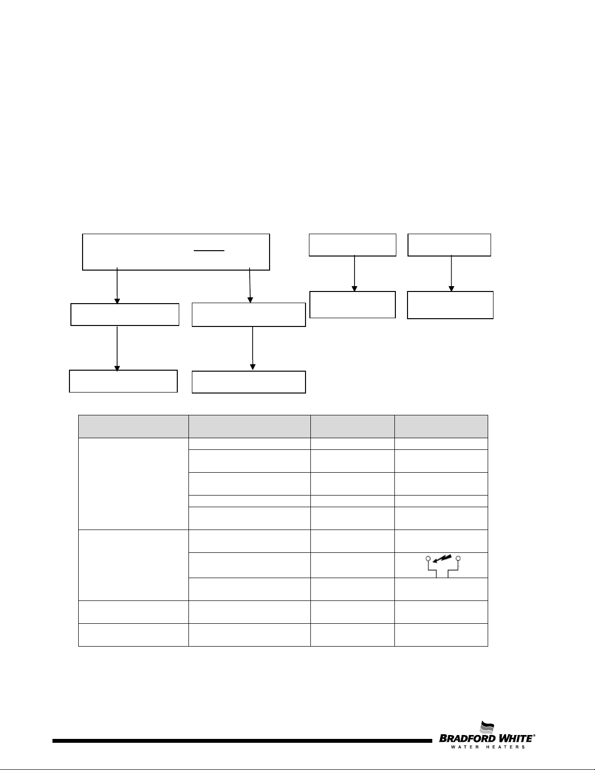
Connection to
the control unit
Flow Sensor
Input
ON
120 V
60 Hz
Thermal fuse with
continuity
Ionization reading
Input
0 µA
Ohm Value inside
range
Turbine detects water
flow
Frequency value
to control unit
electrodes
Gas valve solenoid
activation
Ionization detection
(spark stops)
Safety devices monitor
operation
Water Flow Calculation
Procedure
Water Flow = Power
(T
set
– T in)
Flow ≥ 0.45
Burner ON
Flow < 0.45
Burner OFF
Burner On
Solar Mode Operation
Burner Off
T in ≥ T
– 1ºC
T
< T set
Ionization Electrode
Flame is sensed through an ionization electrode, and detection is granted for ionization currents higher
than 0.5 µA. The two ionization electrodes are spaced to allow flame detection on both sides of the
burner.
5. Working Principle / Electric Measurements
Water Flow Detection and Solar Mode Operation
out
set
Operation Action
Standby
(Inputs signals must
be within expected
limits)
Hot Water Demand
(tap opening)
Flame on main burner
Hot Water Delivery
Electrical plug connected Input
Temperature sensors OK Input
Table 10 – Minimum Operation Conditions Signals
Spark to ignition
Result
AC
Input Contact closed
Input
Output
Output 13 V DC
Input I > 0.5 µA
Input
Page 38
38
Page 39
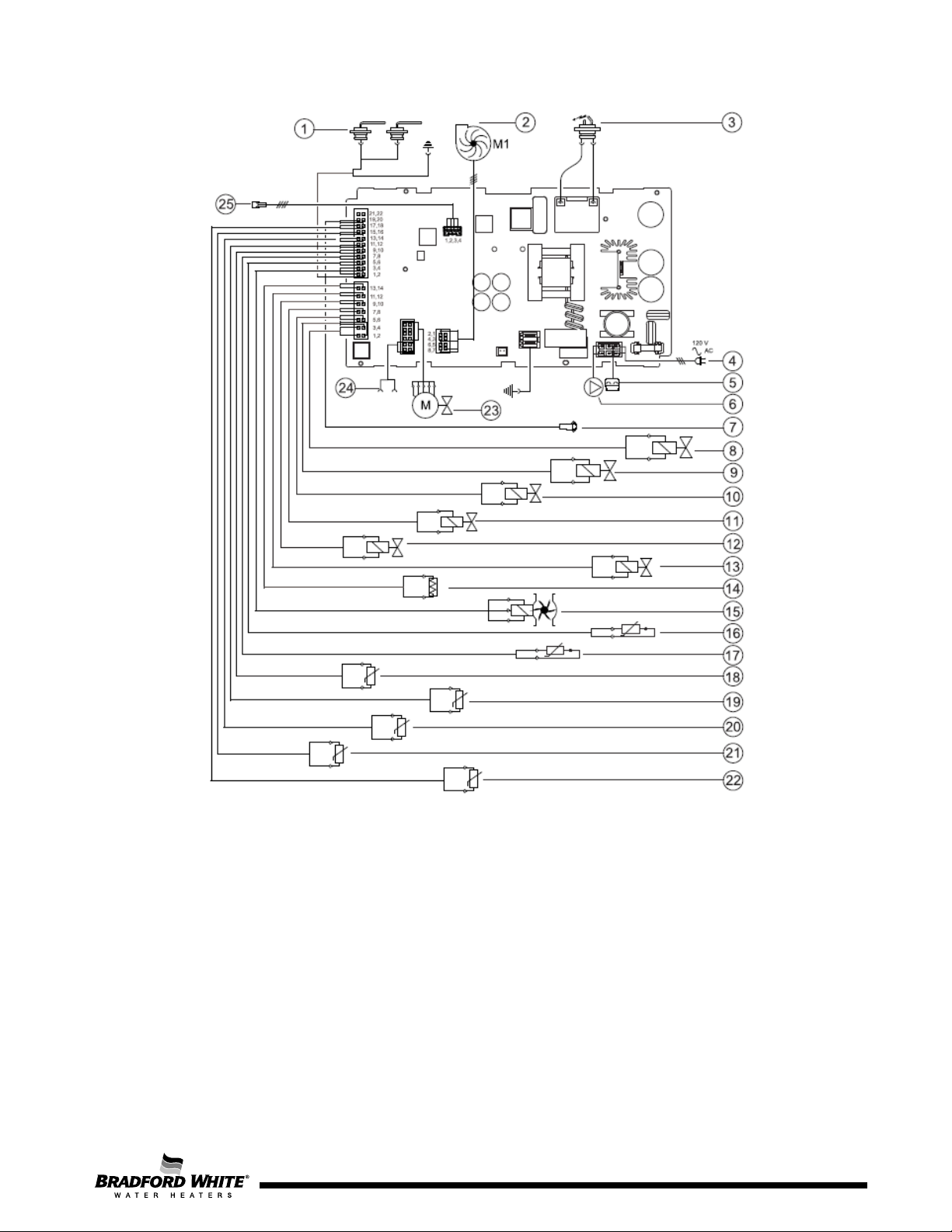
[1] Ionization sensor
[13] Thermofuse
[25] Connection for Recirculation Pump
[2] Fan
[3] Ignition electrode
[4] Power supply
[5] Connection for anti freeze kit
[6] Connection for remote control
[7] Gas valve - Modulation
[8] Water bypass valve
[9] Manifold solenoid 3
[10] Manifold solenoid 1
[11] Manifold solenoid 2
[12] Gas valve – Safety Solenoid
[14] Water flow sensor
[15] Exhaust temperature sensor
[16] Exhaust temperature sensor in heat exchanger
[17] Water outlet bypass temperature sensor
[18] Cabinet air temperature sensor
[19] Heat Exchanger outlet temperature sensor
[20] Water inlet temperature sensor
[21] Water outlet temperature sensor
[22] Water valve stepper
[23] Cascading in/Out
[24] Touch control display
Figure 32 – K Series Electric Wiring Diagram
Page 39
39
Page 40
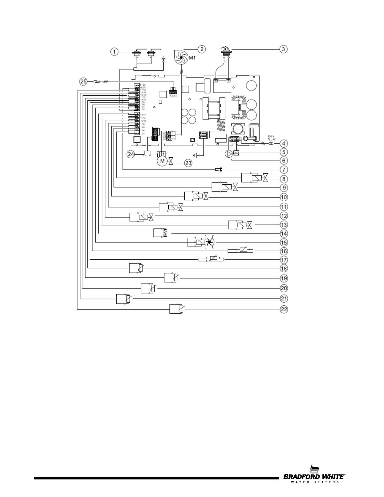
[1] Ionization sensor
[13] Thermofuse
[25] Connection for Recirculation Pump
[2] Fan
[3] Ignition electrode
[4] Power supply
[5] Connection for anti freeze kit
[6] Connection for remote control
[7] Gas valve - Modulation
[8] Water bypass valve
[9] Manifold solenoid 3
[10] Manifold solenoid 1
[11] Manifold solenoid 2
[12] Gas valve – Safety Solenoid
[14] Water flow sensor
[15] Exhaust temperature sensor
[16] Exhaust temperature sensor in heat exchanger
[17] Water outlet bypass temperature sensor
[18] Cabinet air temperature sensor
[19] Heat Exchanger outlet temperature sensor
[20] Water inlet temperature sensor
[21] Water outlet temperature sensor
[22] Water valve stepper
[23] Cascading in/Out
[24] Touch control display
40
Figure 33 – L Series Electric Wiring Diagram
Page 40
Page 41
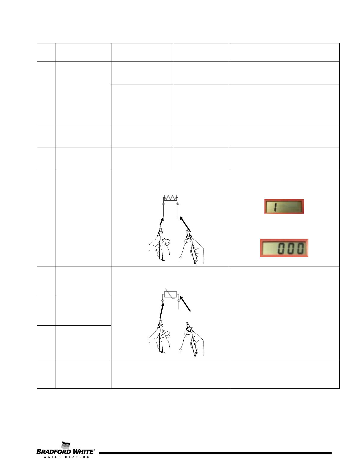
Component
Description
Measuring Wire
Colors
When replaced by a new spare part,
in PA (Actuator) menu of display.
When replaced by a new spare part,
in PA (Actuator) menu of display.
Multimeter for Resistance Measurement R (Ω)
ID
Red-Blue GND
14 Water Flow Sensor
Yellow-Blue GND
(pulse frequency ~Hz)
Water Valve Stepper
22
8 Bypass Water Valve Red – Red 0 v to 24 V dc
13
Motor
Thermal Fuse
(actuation
temperature:
237ºF / 114ºC)
Black – Red
White cable – White cable
Value Remarks
5 VDC Control power
≈ 2.5 to 2.9 V
or
5 V dc
DC
On: ≥ 0.45 gpm (1.7l/min)
Note: See Table 9 to check
correspondence between water flow and
frequency signal.
calibration is needed using MF parameter
calibration is needed using bP parameter
Circuit Open – Not Ok
(infinity – no continuity)
Circuit Closed – Ok
(0 Ohm – continuity)
19
21
20
18
Heat Exchanger
temperature NTC
Outlet water
temperature NTC
Inlet water
temperature NTC
Air Box
temperature NTC
10 kΩ NTC
220 kΩ NTC See corresponding values in Table 12.
Table 11 – Electric Values
See corresponding values in Table 13.
Page 41
41
Page 42
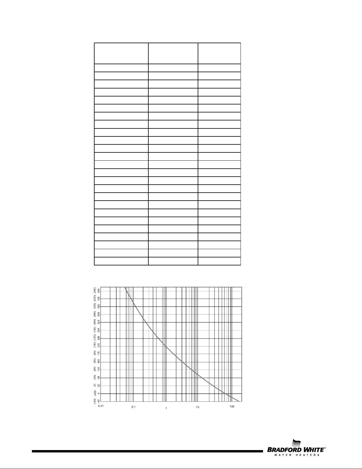
Operating
(ºC)
Operating
(ºF)
-10
14
1373
-5
23
1034
0
32
784.7
5
41
600
10
50
462.1
15
59
358.4
20
68
279.9
25
77
220
30
86
174
35
95
138.5
40
104
110.9
45
113
89.24
50
122
72.24
55
131
58.78
60
140
48.08
65
149
39.51
70
158
32.63
75
167
27.07
80
176
22.56
85
185
18.88
90
194
15.87
95
203
13.39
100
212
11.34
105
221
9.642
110
230
8.228
Temperature
Temperature
Resistance
(KΩ)
Table 12 – NTC Resistance Values for Air Box NTC
Figure 34 – Diagram for Combustion NTC’s
42
Page 43
Operating
(ºC)
Operating
(ºF)
R
(KΩ)
0
32
30.34
30.4
36.47
5
41
23.674
25.902
28.129
10
50
18.617
20.247
21.878
15
59
14.749
15.95
17.151
20
68
11.768
12.657
13.547
25
77
9.454
10.115
10.777
30
86
7.644
8.138
8.632
35
95
6.218
6.589
6.959
40
104
5.089
5.367
5.646
45
113
4.188
4.398
4.608
50
122
3.466
3.624
3.782
55
131
2.883
3.002
3.122
60
140
2.41
2.5
2.59
65
149
2.009
2.092
2.175
70
158
1.683
1.759
1.835
75
167
1.416
1.486
1.555
80
176
1.197
1.26
1.323
85
185
1.016
1.074
1.131
90
194
0.866
0.918
0.97
95
203
0.741
0.788
0.836
100
212
0.637
0.68
0.722
105
221
0.549
0.588
0.627
110
230
0.475
0.51
0.545
Figure 34 – Diagram Water NTC
Temperature
Temperature
R min
(KΩ)
nominal
R max
(KΩ)
Table 13 – NTC Resistance Values for Water Temperature NTC’s
43
Page 44
Page 44
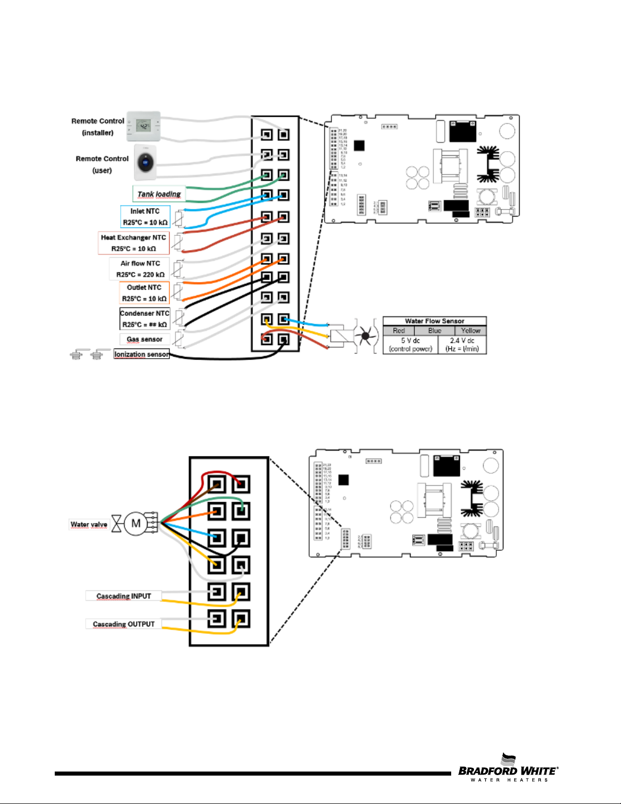
The following pictures show cable location in each connector on the PCB (printed circuit board):
Figure 35 – Sensor Connector with 22 pins
Figure 36 – Water Valve and Cascading System Connector with 12 pins
44
Page 45
Component
Description
Multimeter in position for
µA
~ 0 – 45 V
~ 10.8 – 13.2 V
Mechanically
valve (MV1)
Main safety solenoid
valve (SSV)
~ 20.4 – 24 V DC (open)
Resistance ~ 120 Ω
Solenoid valve
(SV1)
~ 12 – 13 V DC
Resistance ~ 105 Ω
Burner Manifold
Segment 1
Solenoid valve
(SV2)
~ 12 – 13 V DC
Resistance ~ 105 Ω
Burner Manifold
Segment 2
Solenoid valve
(SV3)
~ 12 – 13 V DC
Resistance ~ 125 Ω
Burner Manifold
Segment 3
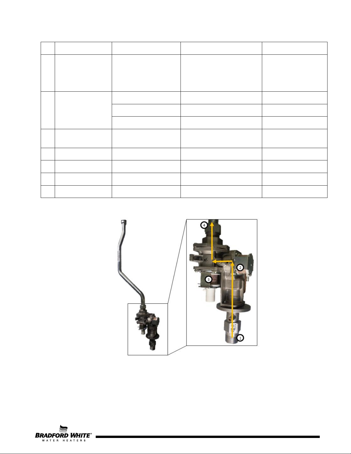
2 – Safety valve (SV1)
4 – Outlet gas
ID
Ionization electrode White wire to ionization
1
Measuring Wire Colors Value Remarks
electrode
Brown-Blue GND
2 Combustion fan
Red-Blue GND
Yellow-Blue GND DC~V (pulse frequency ~ Hz) Feedback from hall sensor
7
modulated
12
10
11
9
Red-Black
Black-Black
Blue-Blue
Black-Black
White-White
Table 14 – Component Electrical Measurements and Values
1 - Gas inlet 3 – Modulation valve (MV1)
current measurement, with
scale for µA range of values
Ionization current > 0.5
DC
~ 4 – 12 V
DC
Resistance ~ 80 Ω
Figure 37 – Gas Valve Solenoids
DC
Note: Cables connected
in series between
ionization cable from
control unit and
electrode.
Supply power
Control power
Modulation Valve
Inlet Safety Valve
Page 45
45
Page 46
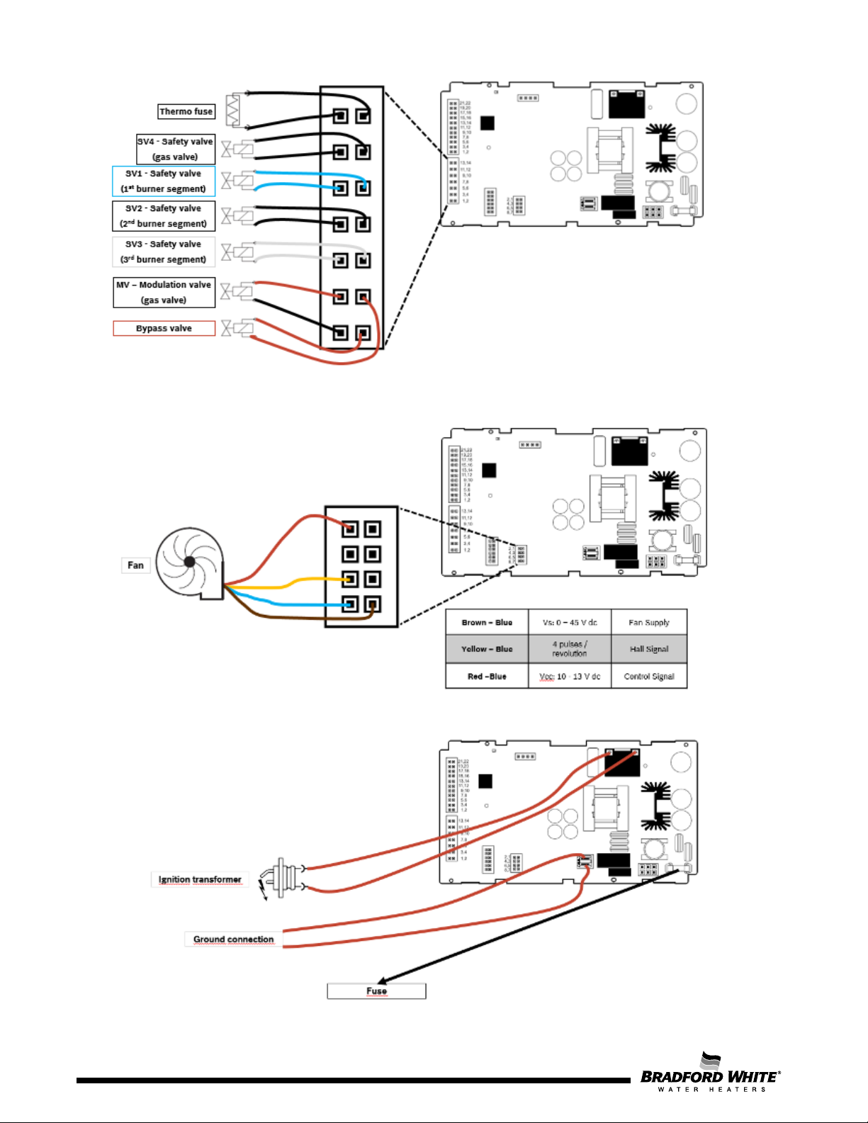
Figure 38 – Gas and Bypass Valve Connector with 14 pins
Figure 39 – Fan Connector with 8 pins
46
Figure 40 – Ignition Transformer
Page 47
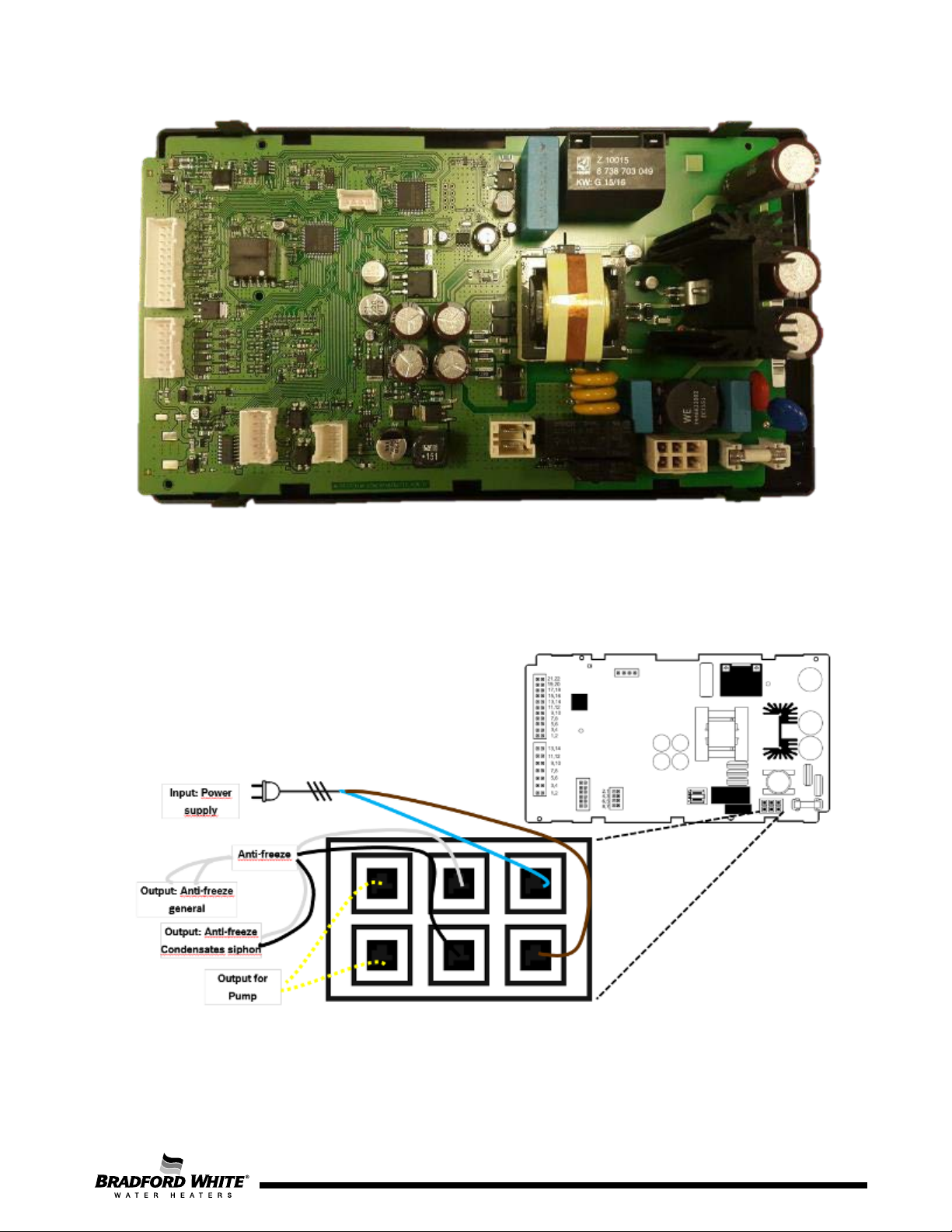
Figure 41 – Inside View of the Control Unit
Figure 42 – Power supply and anti-freeze connector with 6 pins
47
Page 48

Page 48
Mode
Parameter
Setting
P1 (Max Power)
A1
L1
P2 (Min Power)
A2
L2
6. After Sales Service
In order to ensure a correct start-up of the appliance and a correct function after any
intervention on the appliance, the service manual must be read and main recommendations followed
to avoid wrong diagnostic / components replacement and premature failures.
To ensure correct start-up of the appliance and correct function after any maintenance
procedures, the service manual must be read and fully followed to avoid incorrect diagnostics and prevent
incorrect component replacement or premature failure of components or the appliance.
6.1 PCB Replacement:
When replacing the control unit, configurations need to be checked and set accordingly. Not
following precautions will result in potential wrong operation of the unit with abnormal combustion,
noise and temperature instability.
Attention:
Control units are supplied as spare part with the following default values:
• NG = Natural Gas (setting visible in P7)
• Indoor Model (visible in PE – nO)
Recommended Procedures:
st
– Combustion Parameters Registration:
1
- Take note of P1 / P2 combustion adjustment values (settings memorized in factory
regulation);
nd
– PCB replacement
2
- Switch off the electrical supply.
- Unscrew fixation screw of PCB.
- Disconnect the connectors in PCB.
48
- Reassemble all the connections.
Page 49
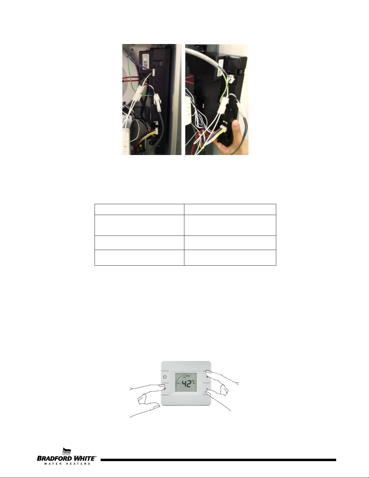
Question
Options
USA
Europe
160 kBTU
199 kBTU
Commercial
Figure 43 – Confirmation of HMI Configuration (gas type)
rd
– Configuration of the New PCB
3
- Switch ON electrical supply.
- Follow configuration tips in HMI.
Region Selection
eV
Appliance Power
Type
Residential
4th Combustion Parameters Configuration
- Confirm P7 = NG or change it to LPG in case of unit operating with Propane.
- Confirm nO (in PE) = Indoor or change it to Outdoor in case of outdoor unit.
- Insert manually the values taken from previous PCB (the default setting in A1 / L1 / A2 / L2 =
20).
Attention:
Procedure to enter in Service Mode (only for outdoor units with inbuilt internal HMI):
From this position and using the selection buttons “+” and “-“, different service modes can be
assessed.
Figure 44 – Service Mode Entry Procedure
49
Page 50
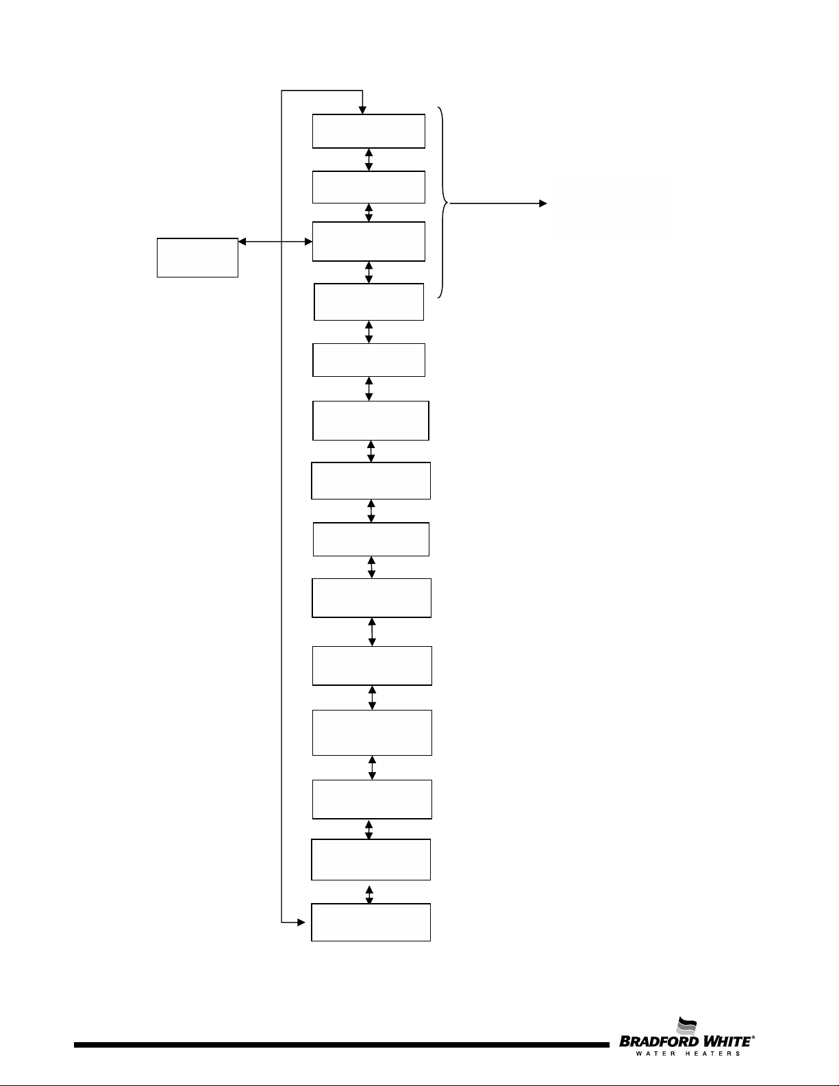
P1
Maximum Power
P2
P3
P4
Information
P5
P6
P7
Gas Type
Set point
P0
(not used)
P8
See Combustion - gas
P9
PA
components
PC
U1
U2
Table 15 – Service Mode Parameters List (1st level)
power adjustments
section for more
details
Minimum Power
Normal Mode
Connectivity
Start-up Delay
Units Set
Backlight control
Purge mode
Calibration of
Cascading mode
Auto Adjust L1
50
Auto Adjust L2
Page 50
Page 51
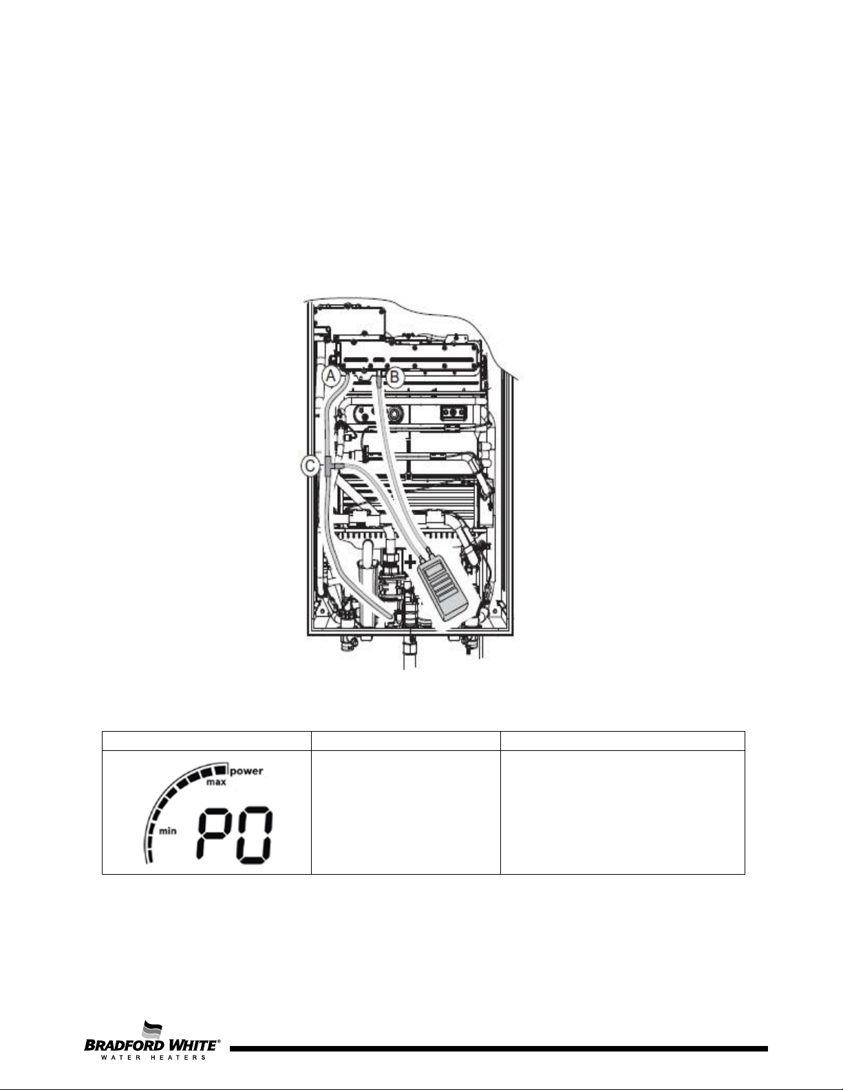
Combustion – Gas Power Adjustment Parameters
Technician Level
Comments
B) Gas Pressure
- P
burner
A) Fan Pressure
- P
air
C) Pressure Tee
(Field Supplied)
The adjustment of the appliance for minimum (P2) / maximum (P1) power operation may be needed
under the following conditions:
- Gas valve replacement – run the U1 and U2 to find L1 / L2 values according characteristic of
new gas valve;
- Fan replacement – use flue gas analyzer as described in manual to find correct setting of A1 /
A2 (air flow);
The following image indicates the 2 measurement points to be used:
Measurement Point
Measurable values:
Figure 46 – P1 / P2 deltaP Measurement Points
Measurement Point
Measurable values:
The P1 mode can be accessed in the service mode, depending on the adjustment and/or
confirmation need.
Range of value in control unit is from
NOT USED
Spare part default setting is 20
Table 16 – P0
0 to 40
Page 51
51
Page 52
Maximum Power Adjustment
Technician Level
Comments
To keep the appliance in P1 (maximum power adjustment), it is important to assure a minimum water
flow, otherwise the appliance will jump automatically to P2 (minimum power).
160 kBTU: > 3 GPM
199 kBTU: > 4 GPM
Table 17 – Minimum Water Flow Needed to Keep P1
Maximum power burner
adjustment after repairs /
maintenance / gas
conversions
P1 contains the fan speed setting
(A1) and gas power (L1) at
maximum power
(depends on gas type / model)
When P1 is visible, press “P” and enter in the 2nd level accessing
“E” for enter and/or exit P1
Adjustment of air flow
without change gas
conditions
Adjustment of gas flow
without change air
conditions
Range from 0 to 40
Spare part default setting is 20
Range from 0 to 40
Spare part default setting is 20
Table 18 – P1 Sub-Menus
Values in P1 mode are settled according to the appliance selection and gas type from factory. To
check default value or to change parameter, press “Program” button when inside of P1.
52
Page 53
Minimum Power
(Minimum gas and water flow)
Remote control registration
Comments
The P2 mode can be accessed in the service mode, depending on adjustment and/or confirmation
need.
adjustment
Technician Level Comments
Minimum power burner
adjustment after repairs /
maintenance / gas
conversions
When P2 is visible, press “P” and enter in the 2nd level accessing
“E” for enter and/or exit P1
Adjustment of air flow
without change gas
conditions
Adjustment of gas flow
without change air
conditions
P2 contains the fan speed setting
(A2) and gas power (L2) at
maximum power
(depends on gas type / model)
(depends on gas type / model)
Range from 0 to 40
Spare part default setting is 20
Range from 0 to 40
Spare part default setting is 20
Table 19 – P2 Sub-Menus
Not used
Table 20 – P3
53
Page 54
The access to the data visualization mode, is made by entering first in the “service mode” and then,
Diagnostic mode and
visualization mode
This mode helps the
This mode helps
Main recommendation
Sequence of
Parameters in P4
scrolling to the parameter “P4” of the adjustment mode.
Installer Level Technician Level Comments
installer in the
startup to check
parameters such as
water flow through
the appliance and
inlet / outlet
temperatures
Table 21 – P4
By pressing the “P” button while the display shows “P4”, the LCD will enter into visualization mode
and will show “E”, meaning “Exit” from the visualization mode. By pressing “P” button again, the LCD
will show “P4”, i.e. the visualization mode has been exited.
After entering into data visualization mode (showing “E”) and then pressing “+” or “-” button, the
parameter and failure visualization fields can be selected as shown in Table 22.
Comment Value / Unit
Entry / Exit of visualization mode
the technician to
find some
information useful
to adjust and to
check functionality
of the appliance.
is to perform always a
check on the last 10
failures in memory in
order to analyze
eventual problems in
installation that might
need to be corrected
Possible change of set point
without leave service mode and
perform any needed control
Temperature indication
Inlet water temperature
Temperature indication
Hot water temperature
Water flow indication
l/min (±0.5l/min)
ºC or ºF
Temperature read by inlet sensor
ºC or ºF
Temperature read by outlet sensor
ºC or ºF
Indicates water flow measured by
the turbine (l/min or gal/min.)
Page 54
54
Page 55
Components Calibration
Technician Task
Comments
Not existing
Temperature of air in room
sealed box
until
Last 10 Failures for diagnostic
purposes
Table 22 – Visualization Mode Parameters
Temperature read by box sensor
ºC or ºF
Failure 1 is last failure occurred
Failure 2 occurred before Failure1
Failure 3 occurred before Failure2
Failure 4 occurred before Failure3
Failure 5 occurred before Failure4
Failure 6 occurred before Failure5
Failure 7 occurred before Failure6
Failure 8 occurred before Failure7
Failure 9 occurred before Failure8
Failure 10 occurred before Failure9
The following parameter is only applicable when correspondent component is replaced in field.
Only applicable
when components
are replaced
Allows the technician to calibrate
components operation range after a
replacement
Entry / Exit
parameter
Open tap with flow of 5 to 6 l/min or 1.2 to
Calibration of
bypass
1.6 gal/min. The calibration will be done by
itself while calibration of by-pass valve is
being done and successful calibration will
be confirmed on the display
Calibration of
motorized water
valve (stepper
motor)
Open hot water tap in any flow rate and
automatically the unit will close the water
flow and start opening slowly for calibration
Table 23 – PA Sub Menus
55
Page 56
This mode allows the installer to
Cascading Mode
Parameter
configurate the units to operate in
cascading (optional kit with cable
required)
Deactivation of cascading
mode
Selection as Master
Selection as Slave
Table 24 – PC
Press “P” for > 3 sec to define unit as
Master (only 1 unit in system)
Press “P” for > 3 sec to define / confirm
unit as slave
7. Maintenance
To ensure continued efficient operation of the appliance, checking and servicing the appliance at
regular intervals is recommended. The frequency of servicing depends on the individual
installation conditions and use profile, but in general, once a year should be adequate. Any
maintenance work in the appliance must be carried out by a competent person such as a
registered and competent technician. Before any service operation, turn off the gas supply at the
main gas service valve upstream. Carry out the maintenance procedure as described in the
manual.
The service partners have all necessary accessories and tools for maintenance tasks.
56
Page 57
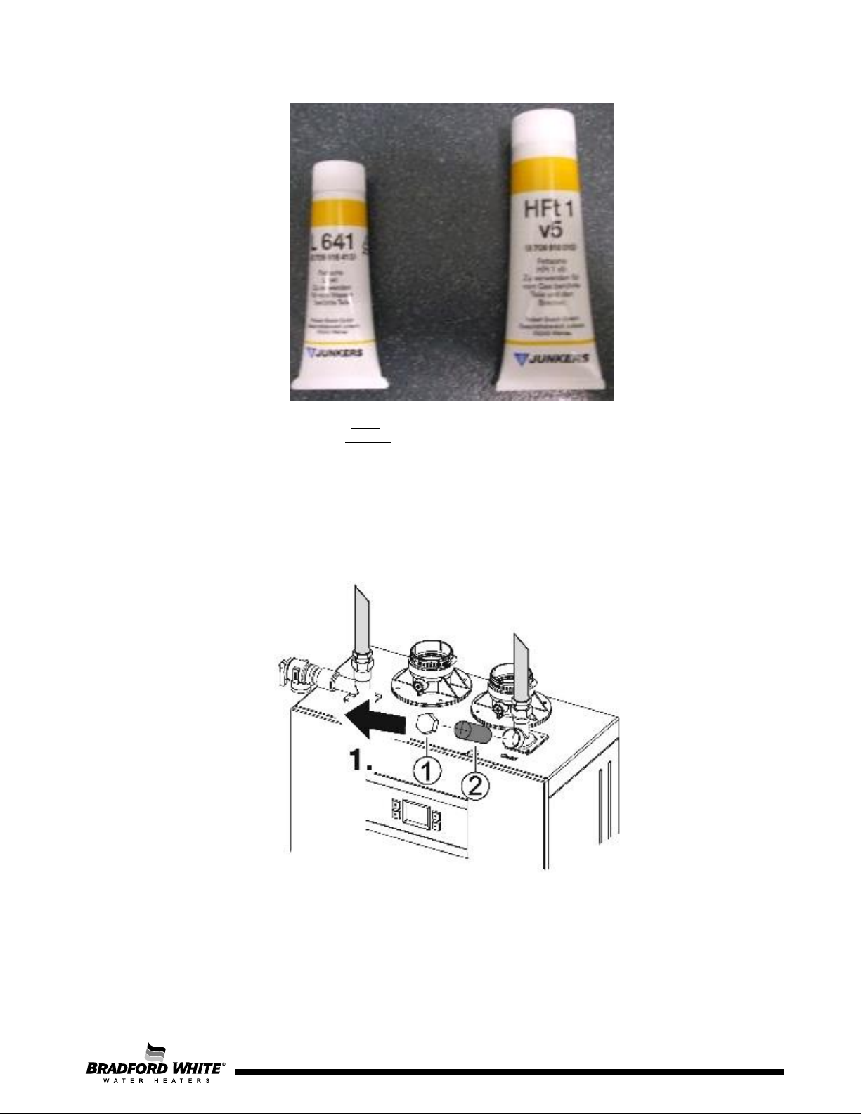
L641 – O-rings in contact with water
HFt1 v5 – Gaskets in contact with gas
Figure 47 – Recommended Lubricants for Connections
Cleaning the Filter
For the cleaning of the filter, first loosen the nut (1), then remove the filter (2) that is fixed in the body
of the inlet water valve. Clean the filter with water and / or air pressure. Assembly is reverse of
disassembly.
Figure 48 – Water Filter Removal
Inspect and clean the heat exchanger when needed. To remove the heat exchanger, begin by turning
off the cold-water supply to the unit. Open the taps to release any remaining water pressure and
drain the appliance.
57
Page 58
Page 58
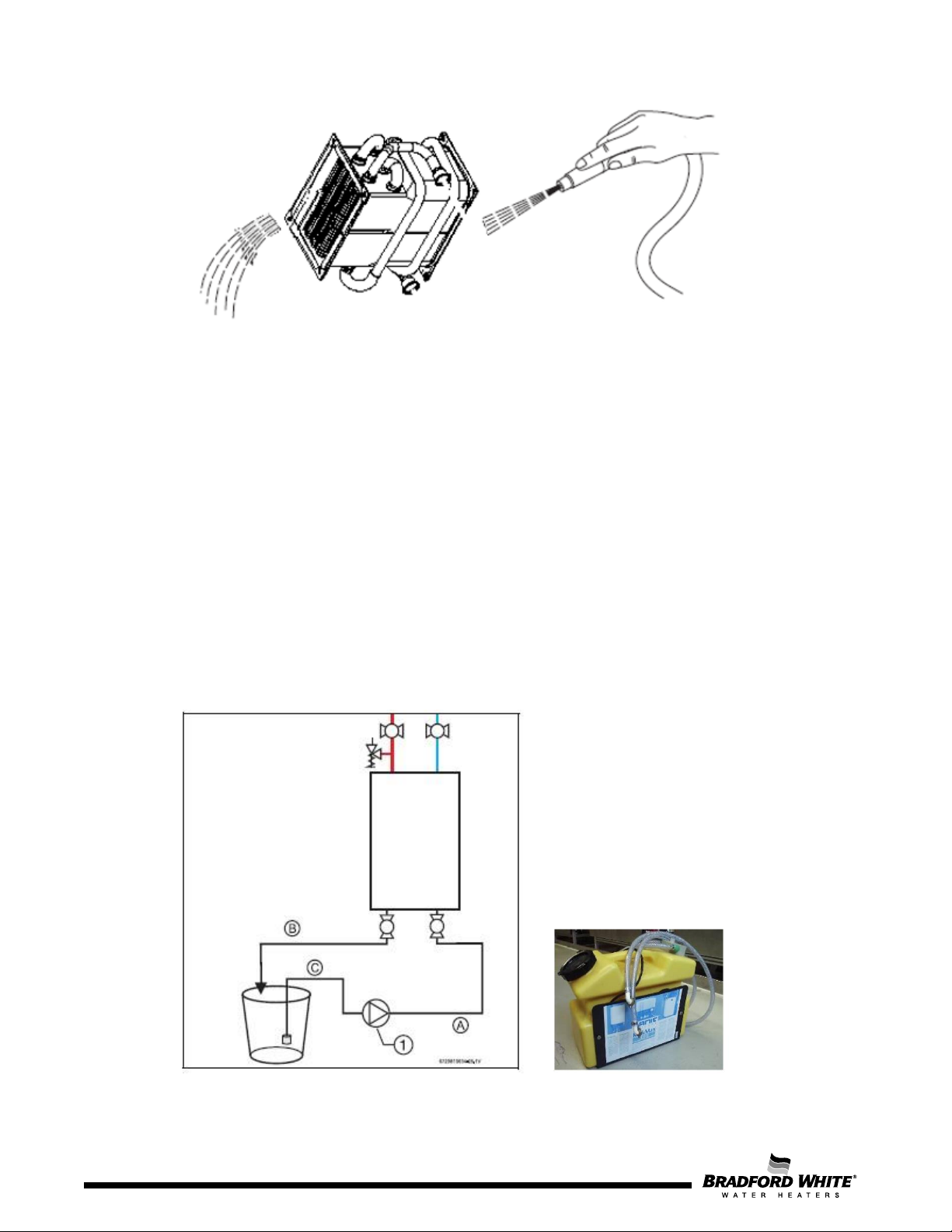
Figure 49 – Heat Exchanger Cleaning
Heat Exchanger Fin Coils
Inspect the heat exchanger fin coils for soot build-up or blockage. If there is evidence of soot build-up or
blockage, the heat exchanger should be removed by a professional and cleaned thoroughly. Soot is an
indication of incomplete combustion and a clear sign of a serious problem. Venting, gas pressure, and
flue gases should be examined to determine the cause of the problem. Damage to the water heater
caused by incorrect installation or adjustment are not covered by the manufacturer's warranty
Take care not to damage the seals that ensure tightness between the heat exchanger, the heat cell,
and collector and ensure correct clearing and alignment of the fins.
In hard water regions it may be necessary to descale the heat exchanger body, using a proper
descaler. Fill the heat exchanger with the descaling solution and let it act until the solution stops
bubbling. Drain and thoroughly wash out the exchanger with clean water.
Warning: Acid/water solutions must be used with extreme caution. Take care not to splash on to the
skin or into the eyes. Wash any affected areas with large amounts of cold water and seek medical
advice.
58
Figure 50 – Heat Exchanger Descaling
Page 59

Page 59
Descaling Using a Pump
▶ Disconnect the electrical supply from the water heater.
▶ Shut off the water supply to the water heater.
▶ Open hot water taps to drain and relieve pressure from the plumbing system.
▶ Shut off hot water valve to the water heater.
▶ Connect a line (A) from the outlet of the circulating pump (installer supplied) to the inlet drain
connection on the water heater.
▶ Using another line (B), connect the outlet drain connection of the water heater. Route the other end
of this line into a descaling reservoir.
▶ Using a 3rd line (C) from the descaling reservoir, connect to the inlet side of the circulating pump.
Install a filter on the end of the line in the descaling reservoir.
▶ Make sure all connections are water tight.
▶ Fill the descaling reservoir with descaling solution so both lines inside are submersed. We
recommend a straight white vinegar solution. If using a commercial descalant, refer to the
manufacturer's instructions for proper dilution ratio.
▶ Ensure both drain connections are open.
▶ Operate the circulating pump.
▶ Make sure there are no leaks and the solution is flowing from the descaling reservoir through the
heater and returning to the reservoir.
▶ Run the solution through the heater until the solution returning to the descaling reservoir comes out
clear. (Changing to a fresh solution may be necessary during this process).
▶ Disconnect all lines and drain all solution from heat exchanger. Properly discard the solution.
▶ Close the inlet drain connection.
▶ Position a container below the outlet drain connection and connect the cold-water supply. Open the
cold-water supply shutoff valve and flush the heat exchanger with clean water.
▶ Close the cold-water shutoff valve and reconnect hot water supply to the water heater.
▶ Close the outlet drain connection.
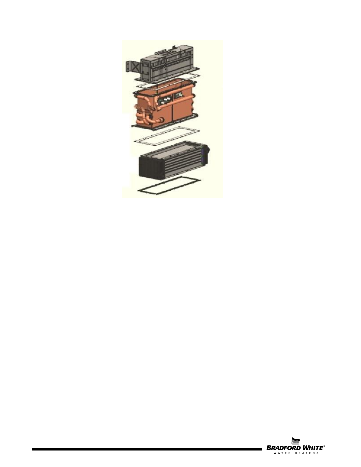
Re-assemble the heat exchanger ensuring its correct position on the two support hooks in the
appliance back plate, good conditions of seals and tightness between heat exchanger, collector and
burner.
59
Page 60
Page 60
Figure 51 – Heat Exchanger
Replacement of Parts
Any service work must be carried out by a competent person such as the technician indicated by the
after sales organization. Before any service operation, turn off the gas supply at the main gas service
valve.
When replacing components, always use the supplied gaskets / sealings provided with the parts and / or
always order the maintenance kit.
60
Page 61
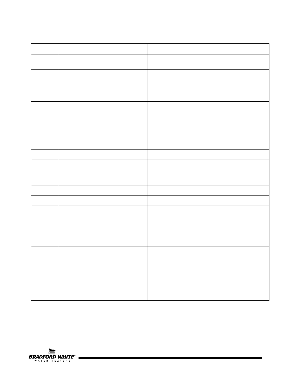
Display
Description
Solution
Either cold or hot water temperature
sensor fault
The appliance automatically regulates the performance of
concentric vent.
The appliance is protected against overheating.
limit.
External Tank temperature sensor is not
fault.
Check temperature sensor and associated connections.1) 2)
loading application is not in use
A3
Flue gas temperature sensor fault.
Check connections or replace sensor.
A4
Cabinet air temperature sensor fault.
Check connections or replace sensor.
Primary or Secondary heat exchanger gas
temperature sensor fault.
A6
Inlet water temperature sensor fault.
Check connections or replace sensor.
A7
Heat exchanger temperature sensor fault.
Check connections or replace sensor.
A8
Outlet water temperature sensor fault.
Check connections or replace sensor.
Incorrect output power. Hot water
LP).
▶ Perform calibration in submenu bP in PA
▶ Close and open a hot water tap.
C8
Main Water valve disconnected
Check water valve connections
C9
Barometric pressure sensor fault
Replace electronic control unit
8. Trouble Shooting
A0
A1
AA
A2
A5
Temperature inside the cabinet is above
158 °F.
Flue gas temperatures above 356 °F after
the primary heat exchange and/or 176 °F
at the exhaust sensor.
installed properly. Temperature sensor
Check temperature sensors and associated connections.
the appliance to avoid overheating.
▶ External air temperature is above 140 °F.
▶ Check for flue leakage inside the appliance or in
▶ Descale appliance. 1)
▶ Check if inlet water temperature is above maximum
▶ Check SA-A1 menu in HMI and select OFF if tank
Check connections or replace sensor.
temperature sensor is not installed
A9
C5 Fault in the bypass valve.
C7 Fan not working
properly. Incoming gas pressure too low
(below 3.5" W.C. for NG or 8" W.C. for
▶ Check incoming gas pressure.1)
▶ Check hot water temperature sensor.
▶ Check manifold solenoids are operating
▶ Check bypass valve connections.
▶ Check fan connections.
Page 61
61
Page 62
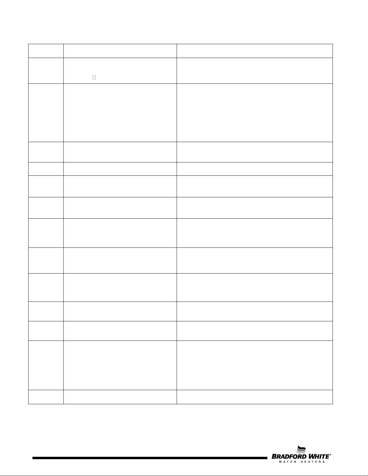
Display
Description
Solution
Air in the water circuit (commissioning).
specified ( 9.24GPM).
CF
- Vent blockage during operation (Flue
Excessive flue vent pressure.
Flow sensor does not detect water
recirculation.
Check pump and connections.
▶ Check recirculation circuit for any blockage.
E0
Internal Failure in ECU
Flow sensor does not detect water recirculation.
▶ Check sensor resistance.
▶ Check sensor resistance.
▶ Check sensor resistance.
Copper heat exchanger gas temperature
the appliance is locked.
To unlock, reset the appliance by touching the ON/OFF
▶ If the problem persists replace ECU.
Error during ionization test. ECU internal
error.
Thermofuse open. Temperature above 237
°F.
▶ Check Air/Gas flow adjustment.
EC
Partial ionization loss 5 times.
▶ Check the gas supply pressure.1)
CA
C1
CE
C3
E1
E3
E4
Water flow above maximum value
vent outlet or air vent inlet). Insufficient
combustion air.
- Air flow insufficient for start-up (Before
flame ignition).
- Flue outlet vent blockage (exhaust
pressure above siphon water column).
Hot water temperature sensor detects
overheating (> 194 °F).
Flue gas temperature sensor detects high
temperature (> 194 °F).
Temperature inside the cabinet is above
194 °F.
▶ Disconnect the appliance and purge hydraulic circuit.1)
▶ Check that water pressure does not exceed 150 psi.
▶ Remove blockage from the exhaust/intake vent.
▶ Check room air inlet requirements. See Chapter 4.7.
▶ Reset the appliance.
▶ Let the appliance cool down and try again.
▶ Let the appliance cool down and try again.1)
▶ Check for flue gas leakage inside the cabinet.
▶ Let the appliance cool down and try again.1)
E5
E7 Internal error
E8
E9
EA
sensor detects temperature above 392 °F,
Flame not detected. Ionization loss 9
consecutive times.
Descale appliance.
▶
button for 3 sec.
ECU may need to be replaced.
Replace thermofuse cable.
▶ Check the gas supply pressure.
▶ To unlock, reset the appliance by touching the ON/OFF
button for 3 sec.
▶ If the problem persists check the ignition electrode or
the ionization electrode.
Page 62
62
Page 63
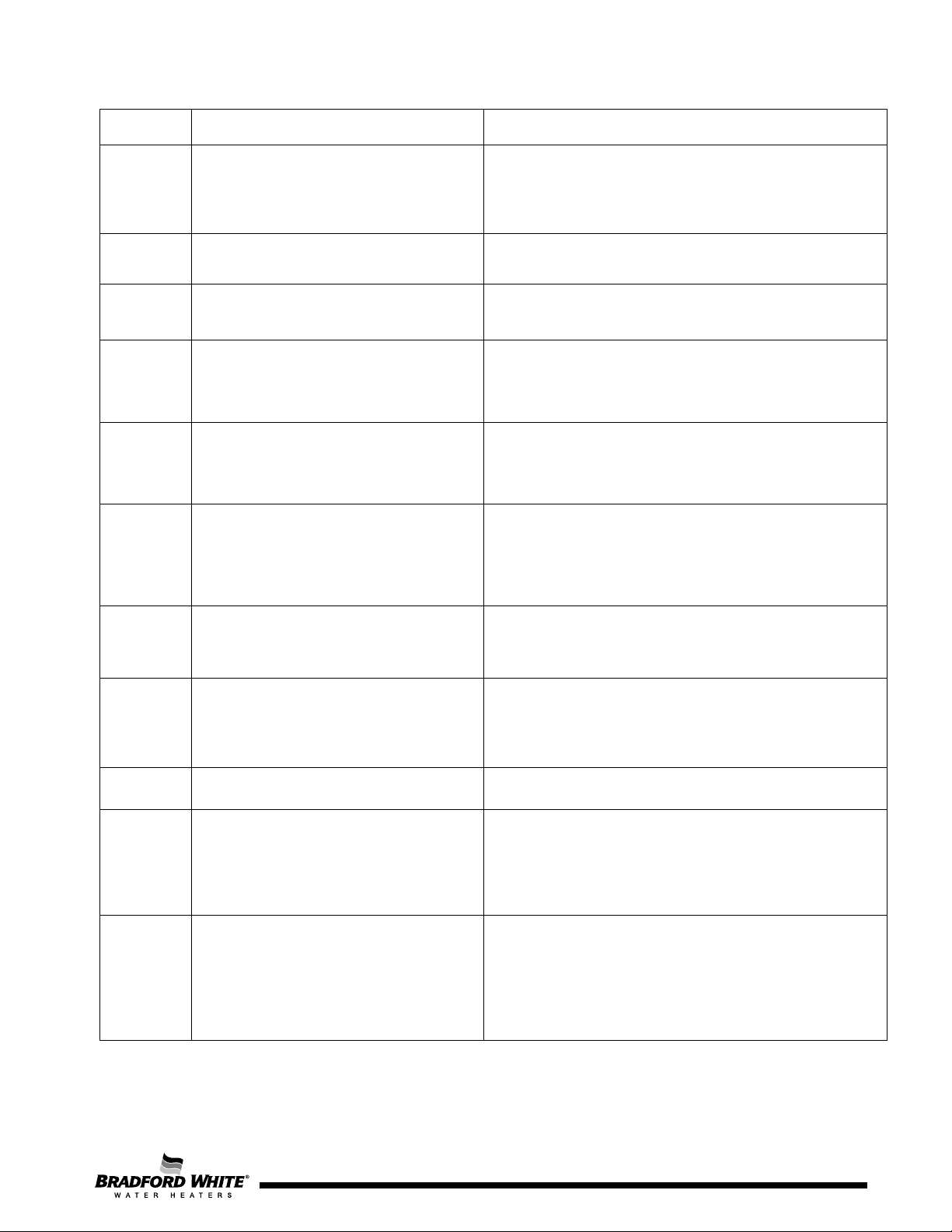
Display
Description
Solution
the ionization electrode.
Modulating gas solenoid valve
disconnected.
▶ Liquid propane gas appliance supplied with NG.
To unlock, reset the appliance by touching the ON/OFF
Check the electrodes and the cable.1)
Check connections.1)
button for 3 sec.
off valve electric circuit.
FC
Buttons touched for more than 30s.
Release the button.
Check that gas supply is the same as appliance gas
Operation manual).
Check that gas supply is the same as appliance gas
manual). Decrease A1 or A2 air adjustment parameter.
▶ To unlock, reset the appliance by touching the ON/OFF
button for 3 sec.
▶ If the problem persists check the ignition electrode or
EE
EF Wrong gas type.
F2 ECU internal error
F3 Memory failure
F7 A flame is detected before gas valve open.
F9 Safety gas solenoid valve disconnected.
FA
Fault in the main gas shut-off valve or gas
manifold shut-off valve.
▶ Check valve connection.
▶ Natural gas appliance supplied with liquid propane gas.
▶ To unlock, reset the appliance by touching the ON/OFF
button for 3 sec.
▶ If the problem persists replace ECU.
▶
button for 3 sec.
▶ If the problem persists replace ECU.
▶
▶ To unlock, reset the appliance by touching the ON/OFF
button for 3 sec.
▶ If the problem persists replace ECU.
▶
▶ To unlock, reset the appliance by touching the ON/OFF
▶ Main gas shut-off valve or gas manifold shut-off valve
stuck/locked.
▶ Check main gas shut-off valve and gas manifold shut-
High Pitch
Noise
Low Pitch
Noise with
Vibration
Combustion flame with gas in excess or
lack of air (combustion adjustment is rich).
Combustion flame with air in excess or
lack of gas (combustion adjustment is
lean).
▶
type (NG or LP).
▶ Check appliance CO2 adjustment (excessive CO2, see
table 19 or 20 located inside your Installation and
▶
type (NG or LP).
▶ Check gas pressure supply (gas pressure too low).
▶ Check appliance CO2 adjustment (low CO2, see table
19 or 20 located inside your Installation and Operation
Page 63
63
Page 64

©2021, Bradford White Corporation, USA. All rights reserved.
www.bradfordwhite.com
General Contact
800-523-2931
General Contact
866-690-0961
For field service, please contact your professional installer or
United States
Canada
International
General Contact
Technical Support
Email
Warranty
Email
Service Parts
Email
Technical Support
Email
Warranty
Email
Orders
800-334-3393
800-531-2111
800-538-2020
800-334-3393
800-531-2111
Orders
local Bradford White sales representative.
 Loading...