

Page 1
PDV(S,T) MODEL SERIES AND INDUCED DRAFT (D80T725,
D65T625) MODEL SERIES WATER HEATERS WITH
HONEYWELL INTEGRATED CONTROL SYSTEM
SERVICE
MANUAL
Troubleshooting Guide
and Instructions for Service
(To be performed ONLY by qualified service providers)
Manual 48061A
PDV80S150
PDV802200
PDV80S250
PDV100S150
PDV100S200
PDV100S250
PDV80T300
PDV100T360
D80T725
D65T625
(PDV80S Shown)
Save this manual for future reference
Page 2

Table of Contents
Page PDV Service Procedure
Introduction 4 - - Tool required for service 4 - - Sequence of Operation 6 - - Troubleshooting 7 - - Thermostat Circuit Testing 24 PDV24-I
Pressure Switch Testing 27 PDV24-II
Pilot Operation Testing 30 PDV24-III
Main Burner Operation Testing 33 PDV24-IV
Main Burner & Pilot Removal & Inspection 35 PDV24-V
Control Board Replacement 40 PDV24-VI
Flue Baffle Removal & Inspection 41 PDV24-VII
Anode Removal & Inspection 42 PDV24-VIII
Generic Parts List - PDV-S 43 - - Generic Parts List - PDV-T 46 - - Generic Parts List - Induced Draft Models 49 - - Gloss a ry of Term s 52 - - -
2
Page 3

FEATURES OF PDV-S MODEL SERIES
Power vented direct vent design, uses a blower to vent the flue produc ts to t he outside and pull combustion air in
from outside the building
Independent Venting - Exhausts flue products and supplies c om bus tion air through two separate 3" or 4" PVC,
CPVC or ABS pipes. Maximum venting distanc e of 40 f t. wi th one 90 degree elbow for each pipe in 3". The
250,000 Btu/hr. model vents with 4" PVC, CPVC, or ABS only. Maximum vent length is 55 feet with one 90
degree elbow in 4" pipe (each pipe) for all models.
Electronic ignit ion - Pilo t is automatically lit and monitor ed by the Honeywell Integrated Ignit ion Control system.
Main burners light from the pilot. Pilot and main burners shut off at the end of each water heating cycle.
Electronic thermos tat and LCD Dis play - Accur ately monitors the tank temperat ur e and the setpoint is easily
adjusted by using the temperature UP and DOWN buttons on the display on the control box cover.
FEATURES OF PDV-T MODEL SERIES
Power vented direct vent design, uses a blower to vent the flue produc ts to t he outside and pull combustion air in
from outside the building
Co-axial Venting (pipe inside a pipe) - Combustion air enter s from outs ide the building through an oute r pip e and
exhausts flue product s thr ough the inside pipe. May be vertically or hor iz ontally vented with a maximum venting
distance of 19'-6" (19 feet, 6 inches) with one 90 degree elbow.
Electronic ignit ion - Pilo t is automatically lit and monitor ed by the Honeywell Integrated Ignit ion Control system.
Main burners light from the pilot. Pilot and main burners shut off at the end of each water heating cycle.
Electronic thermos tat and LCD Dis play - Accur ately monitors the tank temperat ur e and the setpoint is easily
adjusted by using the temperature UP and DOWN buttons on the display on the control box cover.
FEATURES OF INDUCED DRAFT MODELS
High Capacity power vente d desi gn, uses a blower to pull the flue products out th e water heater. Designed to
vent vertically through 8 inch diameter type B venting system. Uses room air for combustion.
Electronic ignit ion - Pilo t is automatically lit and monitor ed by the Honeywell Integrated Ignit ion Control System.
Main burners light from the pilot. Pilot and main burners shut off at the end of each water heating cycle.
Electronic thermos tat and LCD Wat er Heater Control Display - Accurately mon itors the tank temperature and the
setpoint and is easily adj us ted by us ing the temperature UP and DOWN buttons on the dis play on the control box
cover.
FEATURES OF HONEYWELL INTEGRATED CONTROLS SYSTEM
Attractive digital water heater display on control panel for setting and displ ay ing the temperature
setpoint. Pressin g temper ature up and down buttons changes the temperature setpoint. Same
water heater display used on all models. Temperature format may be displayed in degrees F or
degrees C.
Single control board with plug in wir ing controls temperature, ignition, and blower operation.
Reduced number of parts for ser v ic ing and wir ing.
Plug in wiring reduces chance of miswiring.
Water heater display will show diagnostic codes in the event the water heater needs servic ing.
Aids in diagnosing and servicing the water heater.
Water heater display can show previous error code history to further aid in servicing the water
heater.
3
Page 4

Introduction
It is intended for this manual to be used by qualified service personal for the primary purpose of
troubleshooting analysis and repair of the Bradford White PDV & Induced Draft Series Water
Heaters. Understanding the sequence of operation section of this manual will contribute greatly to
troubleshooting this product.
Troubleshooting begins by noting the error code, if any, on the water heater control display and
finding the section in this service manual for diagnosing the problem for this error code. This step
by step procedure beginning on page 5 will direct the service provider to a series of test
procedures to determine root cause of failure.
Contact Technical support immediately if diagnosis is not determined using the methods described
in this service manual.
Tools Re quired fo r Ser v i ce
Manometer: Two types available, a liquid “U” tube type or a digital (magna-helic)
type. This device is used to measure gas and/or air pressures and
vacuum.
Multi-Meter: A digital type is strongly recommended. This device is used to measure
electrical values. The meter you select must have the capability to
measure volts AC, volts DC, Amps, micro-amps and ohms.
Thermometer: Used to measure water temperature. An accurate thermometer is
recommended.
Water Pressure Gage: Used to measure water supply pressure. Also used to determine tank
pressure by adapting to the drain valve of the heater.
Jumper Leads: A length of wire (12" min.) with alligator clip at both ends.
Various Hand Tools: Pipe wrench, channel locks, open end wrench set, 12" crescent wrench,
Allen wrench set, torx bit set, screw drivers (common & phillips), long
reach (12") magnetic tip phillips head screw driver #2 tip, ¼" nut driver,
pliers (common & needle nose), socket set including a 1-1/16 deep well
socket, wire cutters, wire strippers, wire crimpers, torpedo level, small
shop vac, step ladder, and flashlight.
4
Page 5
Specifications
Power Supply
Current Draw
Gas Supply Connection
Approved Gas Type
Gas Pressure (Nat. & L.P.)
Venting System
Dedicated 120 VAC, 60 Hz., 15 A
Less than 5 Amps
PDV-S & PDV-T MODELS: 3/4" NPT Minimum connec tion to gas valve.
INDUCED DRAFT MODELS: 1" NPT Minimum conncec tion to gas valve.
Schedule 40 black iron pipe recommended for all models.
Natural or Propane. Gas supply must matc h the gas type listed on the
water heater rating labe l.
Manifold Pressure : 4.5 " w.c . nat ur al gas , 10. 0" w.c. L.P.
Gas Supply Pressure: At least 1" above manifold pressure with water heater
operating, 14" w.c. maxim um
PDV-S MODELS:
Power vented through either 3" or 4" diameter PVC, CPVC, or ABS pipe for
150,000 or 199,999 Btu/hr . models, 4" only for 250,000 Btu/hr . m odels .
Refer to the installation instruction manual for further information on venting
lengths and installa tion requirements.
PDV-T MODELS:
Power vented through Co-axial Venting (pipe inside a pipe) - Combustion air
enters from the outside the building through an outer pipe (200m m diam .)
and exhausts flue produ cts through the inside pipe (130mm diam.) . Ref er to
the installation instruction manual for further information on venting lengths
and installation req uir em ents.
Minimum Clearance for Serv ic ing
Maximum Water Supply Pressure
Thermostat Sensor(s)
Control Board
Control Display
Transformer
Pilot
INDUCED DRAFT MODELS:
Connect 8” vent to blower vent col lar for venting through a chimney or type
B vent only. Vertical venting only.
30" Front Clearance, 16" Top, 2" Sides and Rear
150 PSI
Redundant thermister with 11,900 + or - 0.5% ohms resistance at 70 deg. F.
Sensor inside well for lower se ns or . PDV-T model s er ies and Induced Draft
models also use an upper sensor (dua l sen so rs fo r thes e mod els ) .
Honeywell Integrat ed Control Board for Temperature Control, Induced Draft
Blower, and Ignition Control Functions. Operates on 24 volts AC current
from transformer. Single s ens or boar ds for PD V-S mod els and dual s ens or
boards for PDV-T models and Indu ce d Dra ft model s .
Honeywell LCD Control Display with Temperature Setpoint, Format, and
Error Code Display in User Mode, Diagnostic Functions in Service Mode.
Communicates with Contr ol B oar d. 24 volts AC. Same control display used
on all models.
120 VAC Primary, 24 VAC Secondary, 40 VA
Intermittent Pilot with Spark Electrode and Flame Sensor monitored by
Control Board
Induced Draft Blower
PDV-S MODELS: 115 VAC, 60 Hz., 4.3 Amps.
PDV-T MODELS AND D80T725, D65T625: 115 VAC, 60 Hz., 3. 6 Amps.
5
Page 6
Sequence of Operation
1 Thermostat calls for heat:
.
The relay closes on the control boar d, sending line voltage (115-120 volts) from “inducer” term inals #5 and 3 on the
control board to the induced draft blower.
The blower starts and when sufficient vacuum is achieved, the pressure switch closes and completes the 24 volt
2
circuit between termi nals 1 and 3 on the Cont r ol Pl ug to t he the board, allowing the ignition s equence to proceed.
The blower “purges” any remaining combustion products from the prev ious c y cle for 15 seconds before allowing the
pilot to light. This is the pre-pur ge per iod of the ignition cycle.
3
Trial for ignitio n (thr ee 90 s ec ond ignition trials, with 75
second pauses between trials).
Control Board simultaneously sends:
1. 24 volts from control pin terminal #8, to “MV/PV”
terminal of gas valve (common terminal).
2. 24 volts from control pin terminal #2, to “PV”
terminal of gas valve to establish
gas flow at pilot.
3. Low current high voltage from “ sp ar k”
terminal, to generate spark at the pilot and
ignite pilot gas fl o w .
4. Pilot flame proving si gnal ( m eas ur ed in
micro-amps). from the “sense” terminal, to
prove pilot flame.
4
Once pilot flame is proven, sparking will stop.
Once sparking stops, 24 volts is sen t from c ontrol pin
5
terminal #5 on control board, to “M V” te rminal on gas valve
to establish main burner gas flow. Main burners ignite from
the pilot flame.
The control board consta ntly monitors pilot flame thro ugh
the flame sensor rod. If pilot flame is los t, pilot and main
burners are shut down. Afte r a 75 second inter-purge
period, the control will attempt to re-light the pilot beginning
at sequence 3 above.
Main burner fires until th e therm os tat is satisfied. The contro l
7
board interrupts 24 volt s through the gas valve circuit. Pilot
and main burners are turned off.
8
The induced draft blower shuts off 5 seconds after the
gas valve closes. This is the post-purge period.
LOCKOUT CONDITION
Control board will go into “Soft Lockout” if the pilot cannot be lit
after 3 ignition trials. The water heater display indicates a lockout
condition by showing an er ror code number (62 or 63) with
“Service Needed” in the display window. Refer to error codes in th e
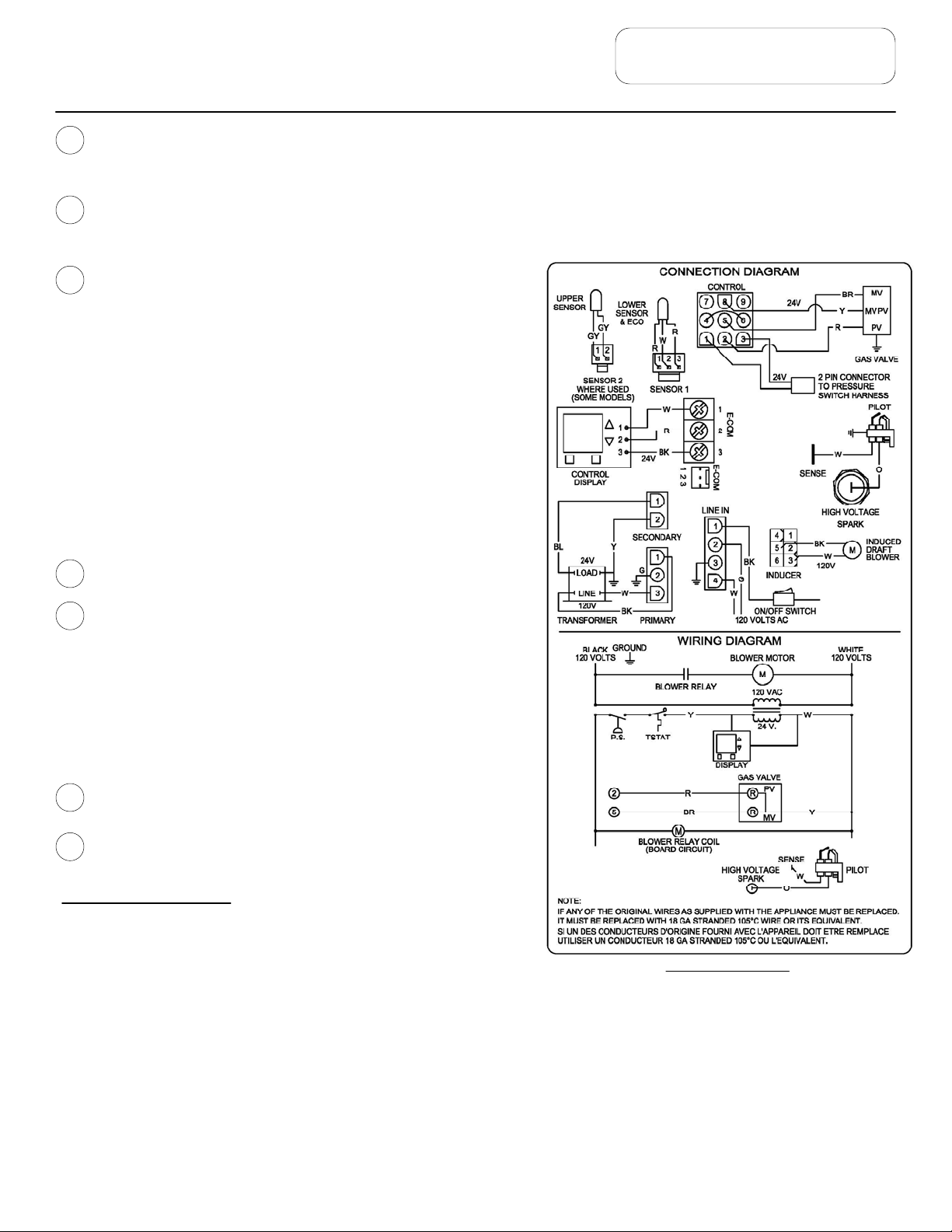
WIRING DIAGRAM
diagnostic sect ion of this Service Manual. In a “Soft Lock out” c ondition,
the control will wai t for 60 m inutes and then make 2 more attempts to light the pilot and establish the main burner s .
Soft lockout res et is ac co mp lis hed by depr es s ing the lower right button under “Res et” for 3 seconds.
If the water heater should reach 200 degrees F, then the high lim it control will shut off the burners and the water heater will
go into a “Hard Lockout”. Error code 65 will be shown in the water heater display. The control can only be reset in the
“service mode”, which is detailed in the next section of this Service Manual.
If the exhaust or intak e term inals become blocked during operation or if the blower motor fails, the pressure switch will open
and error code 29 will appear in the display. When the condition is corrected, the error code will disappear and the water
heater will resume normal operation. No resetting of the control display is needed for t he pr es su re switc h er ro r code.
6
Page 7
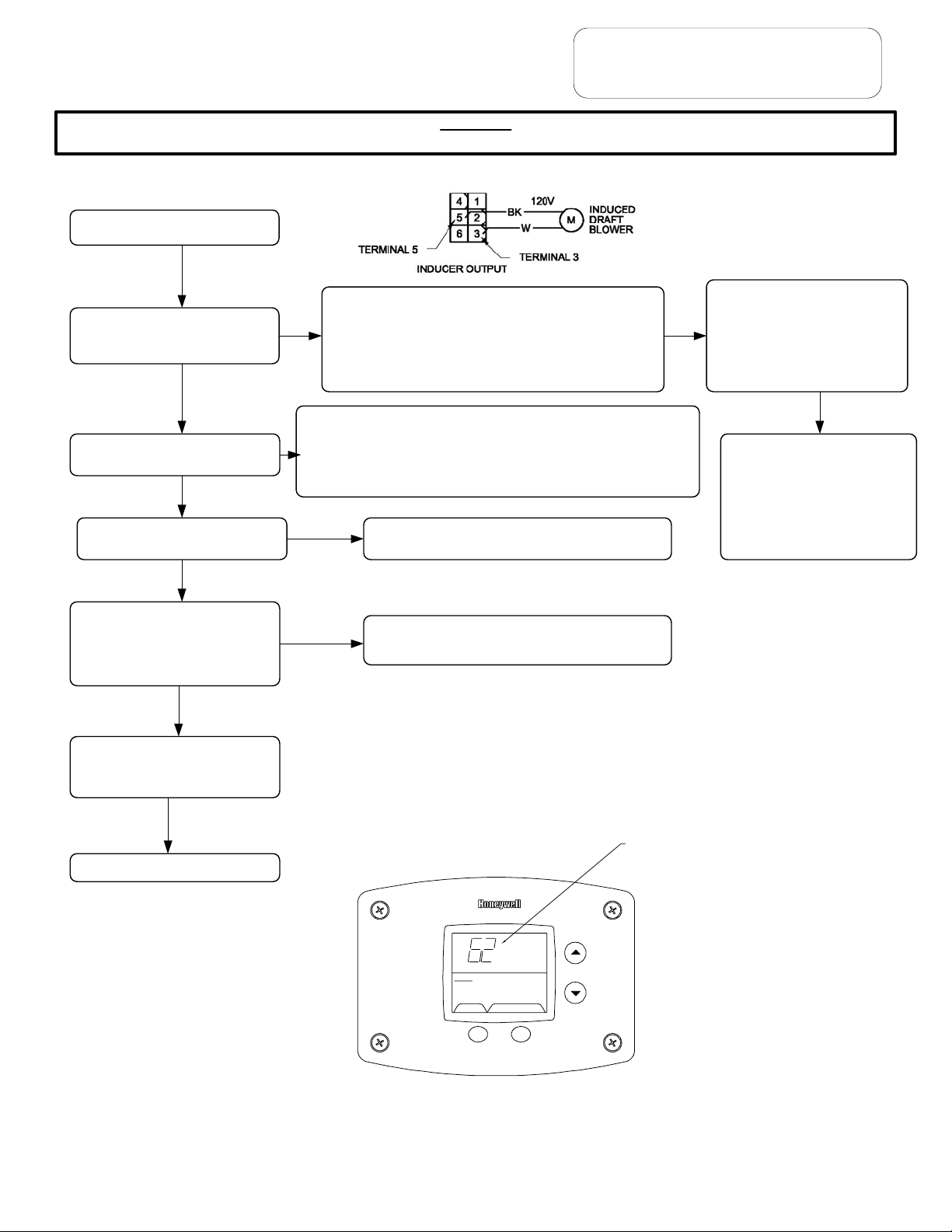
CAUTION
Use Caution Not to Damage Connectors when making Voltage Measurements or Jumping Terminals
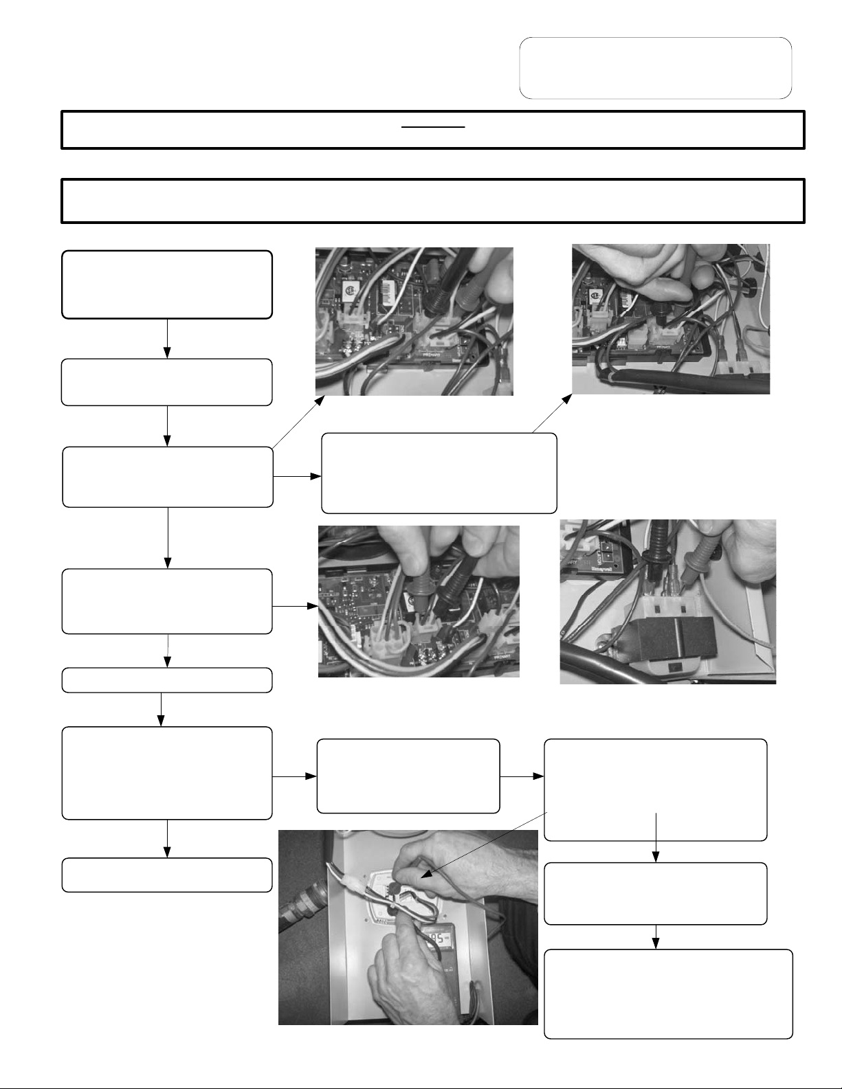
Water Heater Fault: Wate r hea ter does not operate
Display Error Code: Water heat er dis play does not operate - blank display
Check main power supply to wat er
heater - fuse, circuit breaker, plug
receptacle, line cord or wiring to
water heater.
Check to make sure switch on top of
control panel is in the ON position
Checking line voltage to board.
Pins to black and white wires.
Verify Primary and Secondary
voltage at the control board.
Voltage at primary pins 1&3 should be
110-120. If not, check Line In pins 1&4.
Check line cord with volt meter.
Replace line cord if defective.
TROUBLESHOOTING
Checking primary voltage to
transformer from board. Pins to
black and white wires.
If there is not 24 volts at Secondary
pins on the control board, check
transformer. Replace transformer
or wire harness.
Switch on power.
Does water heater display operate?
Does the induced draft blower start
to operate? Increase thermostat
setting if tank is warm.
N
See next page
Checking secondary voltage from
transformer. Pins to blue and yellow
wires.
N
Check wire connections of
board to display. See
illustration.
Checking transformer voltage, front
terminals are 24 volts, rear terminals
are 120 volts.
With the control cover tilted down,
measure the voltage between red and
black wire pin connections to display.
Voltage should be 24 volts AC
measured at the back of the Control
Display.
If no voltage at Display, check wire
harnesses and voltage at E-com
screw terminals on the Control Board.
Replace control display if voltage is
present at back of display pin terminals
(see photo at left). Replace control board if
no voltage is present at E-com terminals
(1&3 and 1&2) to the control display.
7
Page 8
TROUBLESHOOTING
CAUTION
Use Caution Not to Damage Connectors when making Voltage Measur ements or Jumping Terminals
From previous page
Does induced draft blower
operate?
Y
Is there pilot flame?
Y
Does Main Burner operate?
Y
Does burner continue until
thermostat set point is reached?
See setting display in Service Mode
and disp la yi ng temper at ur e
sensors.
Y
Error code #29 on display. Measure voltage at the pin
terminals on the control board between the black and white
N
wires to the blower (terminals 5 and 3 on the “inducer”
output on the board, see imag e above). Make sure the
control display shows “heating” in the status mode.
Increase the setpoint, if it does not show “heating”. Is there
110-120 volts to the blower harness?
Error code #29 on display. Pressure swi tch did no t close. Check for
N
blocked intake or exhaust ve nts, dampe r stuck clo sed, or excessive
vent l ength. See section on “Checking Pressure Switch”. If pressur e
switch closes, and error code 62 appears on control display, pilot is not
lighting or staying lit during the i gnition cycle. Proceed to the s ection
“Pilot Operation Testing”
N
Error c ode #62 on d is play . Se e pil ot ligh ts, n o flam e
signal in the section for “Pilot Operation Testing”
N
Error code #63 on d isplay. See M ain Burner short
cycles in the section under “Main Burner O peration
Testing”
Replace control board if display
shows “heating” and no voltage is
N
present to the blower harness.
Make sure there are no codes for
the temperatur e sensors
(following sections) before
replac in g control boa r d.
If there is voltage from the
control board to the blower wire
harness? Check the voltage at
the connection to the blower.
Replace wire harness if there is
no voltage to the b lower.
Replace blower, if there is
voltage to the blower.
Blower Stops shortly after burners
shut off.
Y
Syste m ok ay
Service Needed
Status
SELECT Lockout RESET
Example of error code shown on control display.
8
Error Code Shown
in Water Heater Display
Page 9
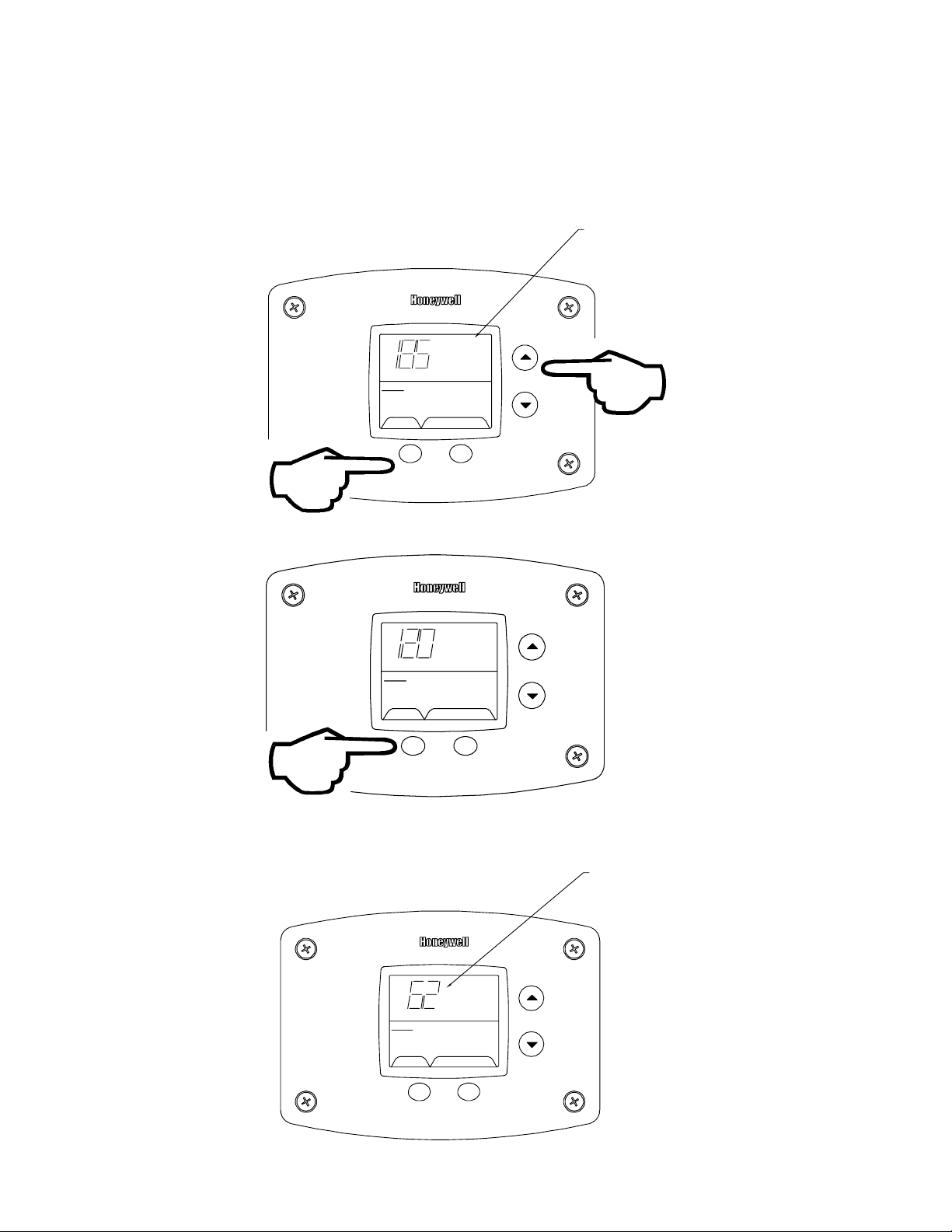
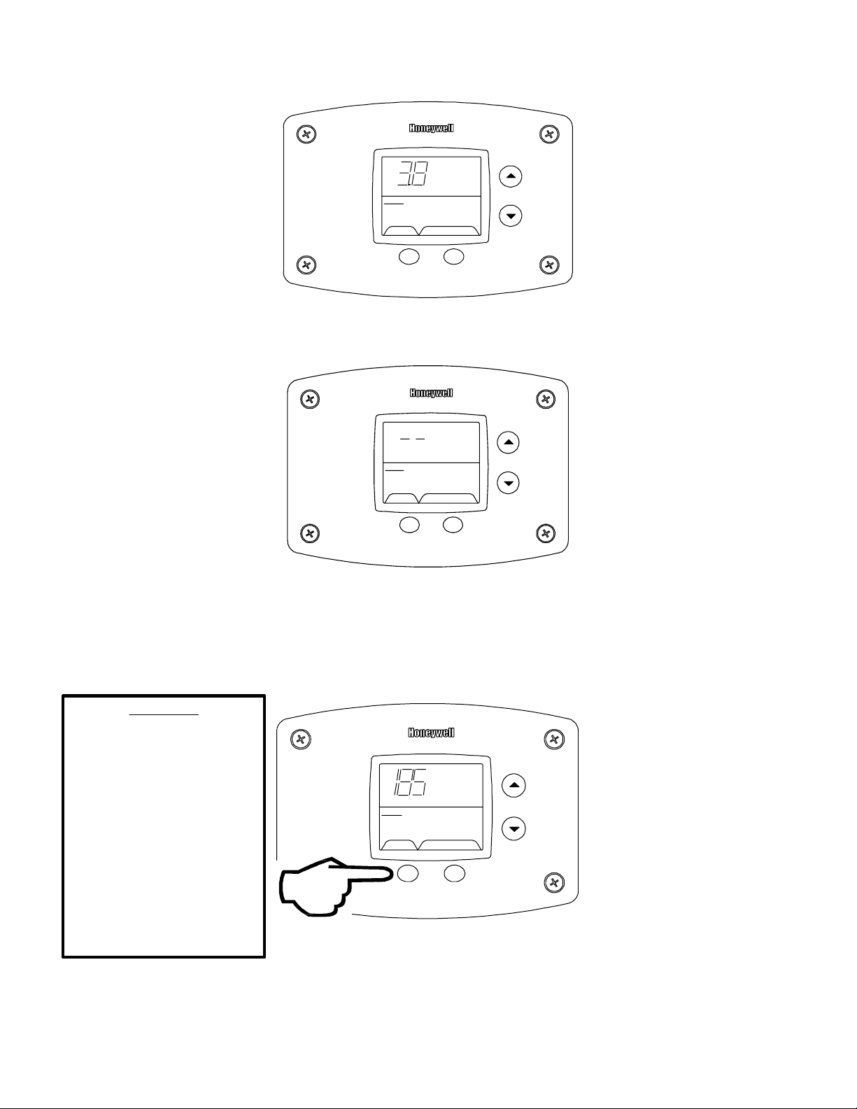
ACCESSING SERVICE MODE ON THE WATER HEATER DISPLAY (FOR SERVICE PERSONNEL ONLY)
e
r
The display has a “service mo de” for ch anging the maximum setpoint and acce ssing information in aiding ser v ic ing of the
water heater. This procedur e is for s er v ic e and ins tallation personnel only . To enter the Service Mode, follow the steps
illustrated bel ow:
Step 1: Press “Select” and “Temperature Up” buttons together and hold for 3 seconds until “Max Setpoint” is shown in the
display.
"Max Setpoint”
next to Temperature
Setpoint value.
Max
Setpoint
idle
Operational
Statu
s
SELECT SET
Step 2: Pressing “Sel ec t” button will change display to next mode
Wate
°F
Temp
idl
Operational
Status
SELECT SET
The following is the sequence of modes available in “Service Mode” by pressi ng the “Sel ect” button:
Error Code Number (Displ ay /Reset). This is only shown if there is an operating error in the “User Mode”.
Error Code Shown
in Water Heater Display
Status
Service Needed
SELECT Lockout RESET
9
Page 10
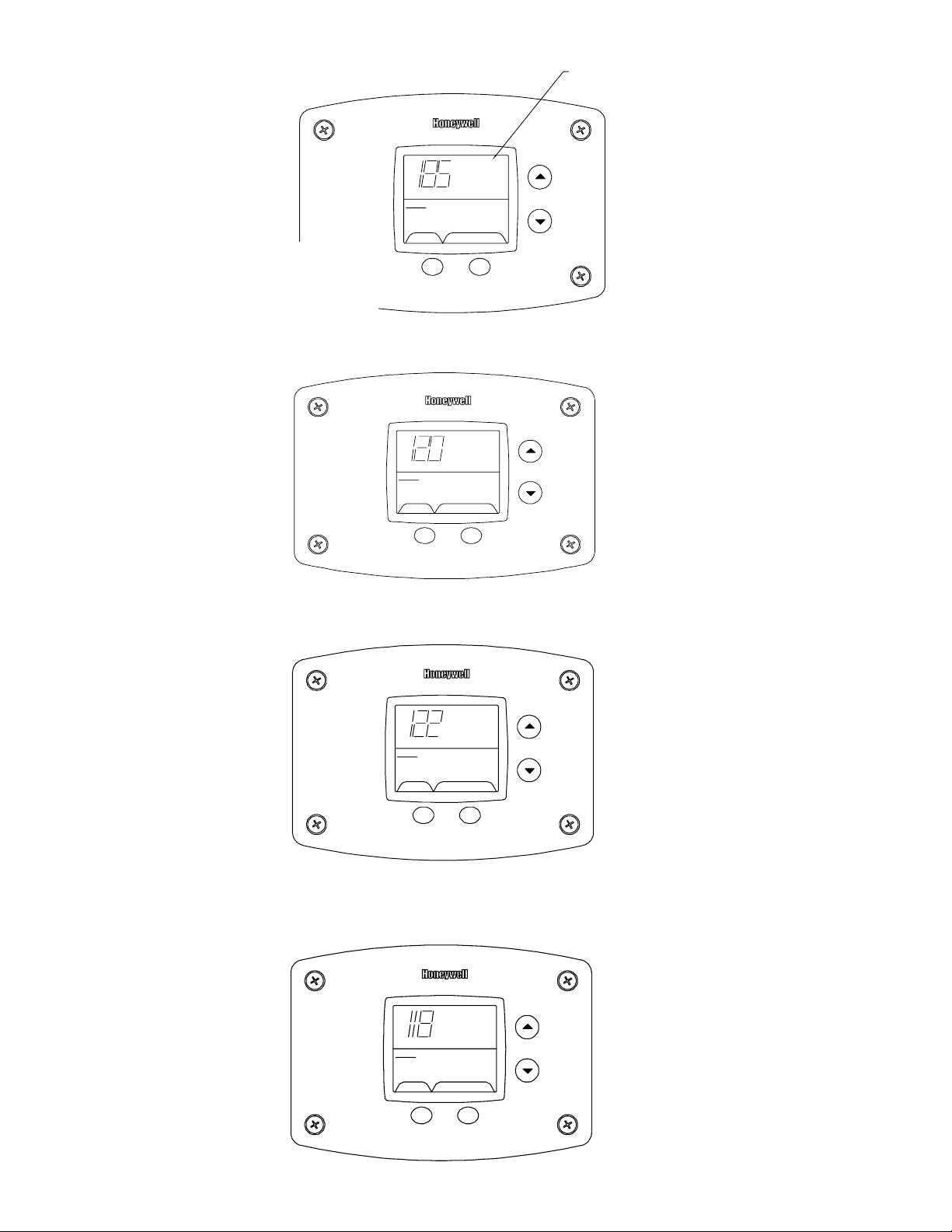
1. Max Setpoint (Display/Change)
e
e
t
°F
Setpoin
idl
Operational
Stat us
SELECT SET
Max
Max Setpoint val ue in
Water Heater Display
2a. Water Temperature Aver age (D is play s av er age if there are two sensors - sensor temperature displayed if single
&
sensor is used).
Water Temp
°F
idle
Operational
Status
SELECT SET
2b. Water Temperature - Upper Sen so r (Displays if there is an upper sensor - some model s)
°F
idl
Operational
Status
Upper Sensor
SELECT SET
2c. Water Temperature - Lower Sen so r (Displays if there are two sensors)
°F
idle
Operational
Status
Lower Sensor
SELECT SET
10
Page 11
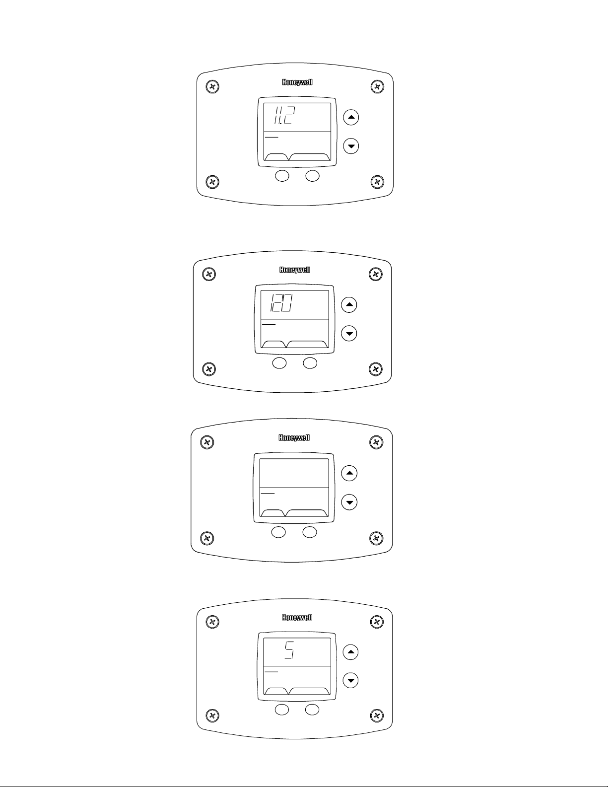
3. Flame Current of Pilot Flame Sens or (Di sp l ay s only in the Heat ing Cy c le)
e
4. Setpoint (Display/Change)
5. °F/°C (Display/Change)
Operational
µA
Flame Current
Heating
Status
SELECT SET
setpoint
°F
idle
Operational
Status
SELECT SET
setpoint
°F/C°
°F
idle
Oper ational
Status
SELECT SET
6. Differential (Display only - shows the differential of the thermostat)
Differential
°F
idl
Operational
Status
SELECT SET
11
Page 12
7. Software Version (Display only )
idle
Operational
Status
SELECT SET
Soft
8. Error Code History (Displ ay s if there are present error codes or up to 10 previous er r or code s). Water Heat er
Display will show a “--“ if there are no error codes.
idle
Operational
Status
SELECT SET
To change the Maximum Setpoint Limit ( Ma x Setp oi nt ) for the te mperature setpoint:
Step 1: In service mode press the “Selec t” button until “Max Setpoint” is displayed.
WARNING
Setting the water temperature
to the ma ximum se t point ca n
result in scalding hot water
delivered to t he faucets. It is
highly recommended that the
maximum setpoint be adjusted
Status
idle
Operational
Max
°F
Setpoint
to the lowest temperature
possible for the needs of the
SELECT SET
installation. Make sure the
water heater control displa y is
not in a public ar ea that can
result in the temperature
settings being improperly
adjusted.
12
Page 13
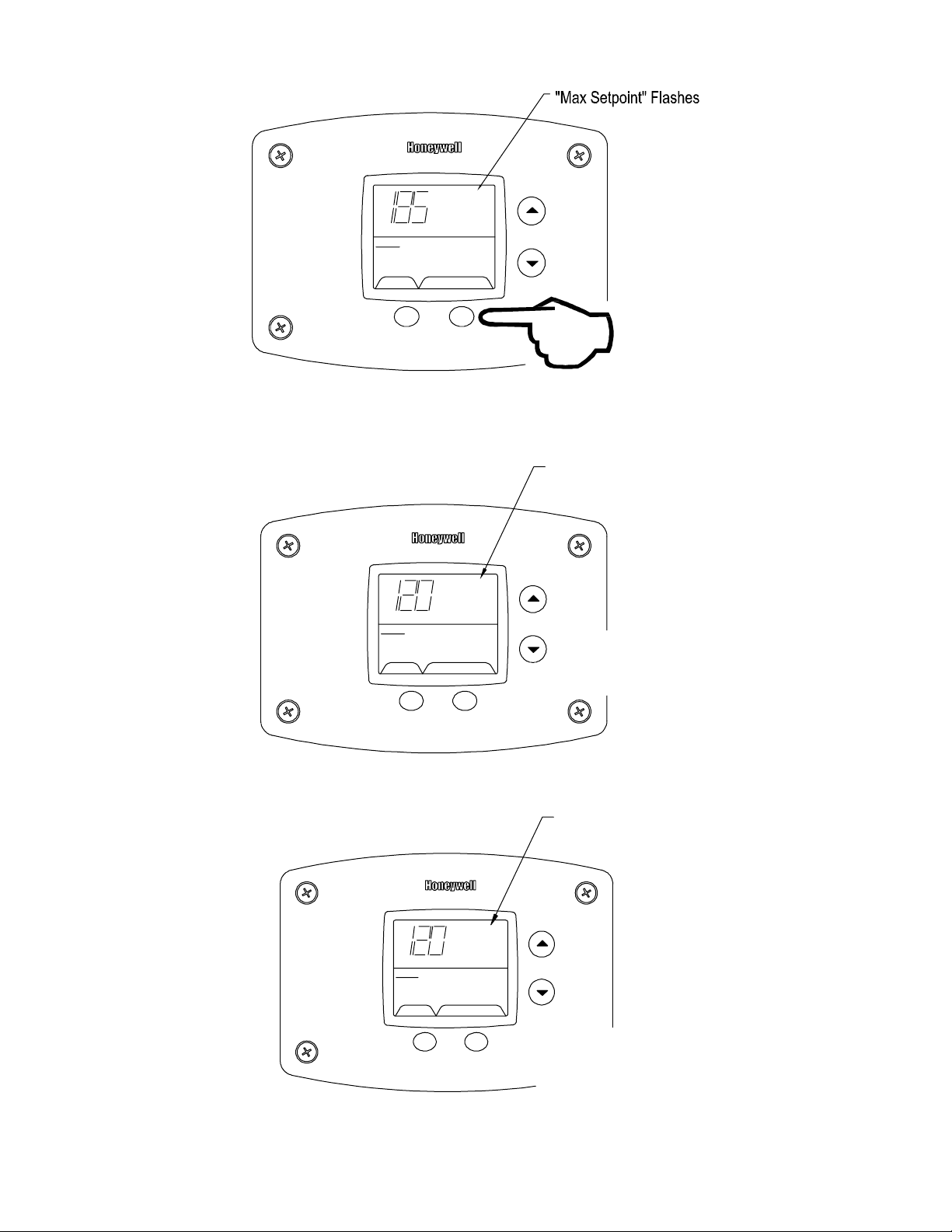
Step 2: Press “Set” button t o enter s ett ing mode. “Max Setpoint” will flash to indicate setting mode.
Max
°F
Setpoint
idle
Operational
Status
SELECT SET
Step 3: Press the “UP” or “DOWN” buttons to change the maximum setpoint value. This will limit the maximum setpoint
the user can select. Note: The maximum setpoint is approximately 180° F.
"Max Setpoint" continues to flash
while making adjustments
Max
°F
Setpoint
idle
Operational
Status
SELECT SET
%
Step 4: Press “Set” button to confirm new “Max Setpoint” value and stop setting mode.
Max
°F
Setpoint
idle
Operational
Status
SELECT SET
"Max Setpoint" stops flashi ng
%
13
Page 14
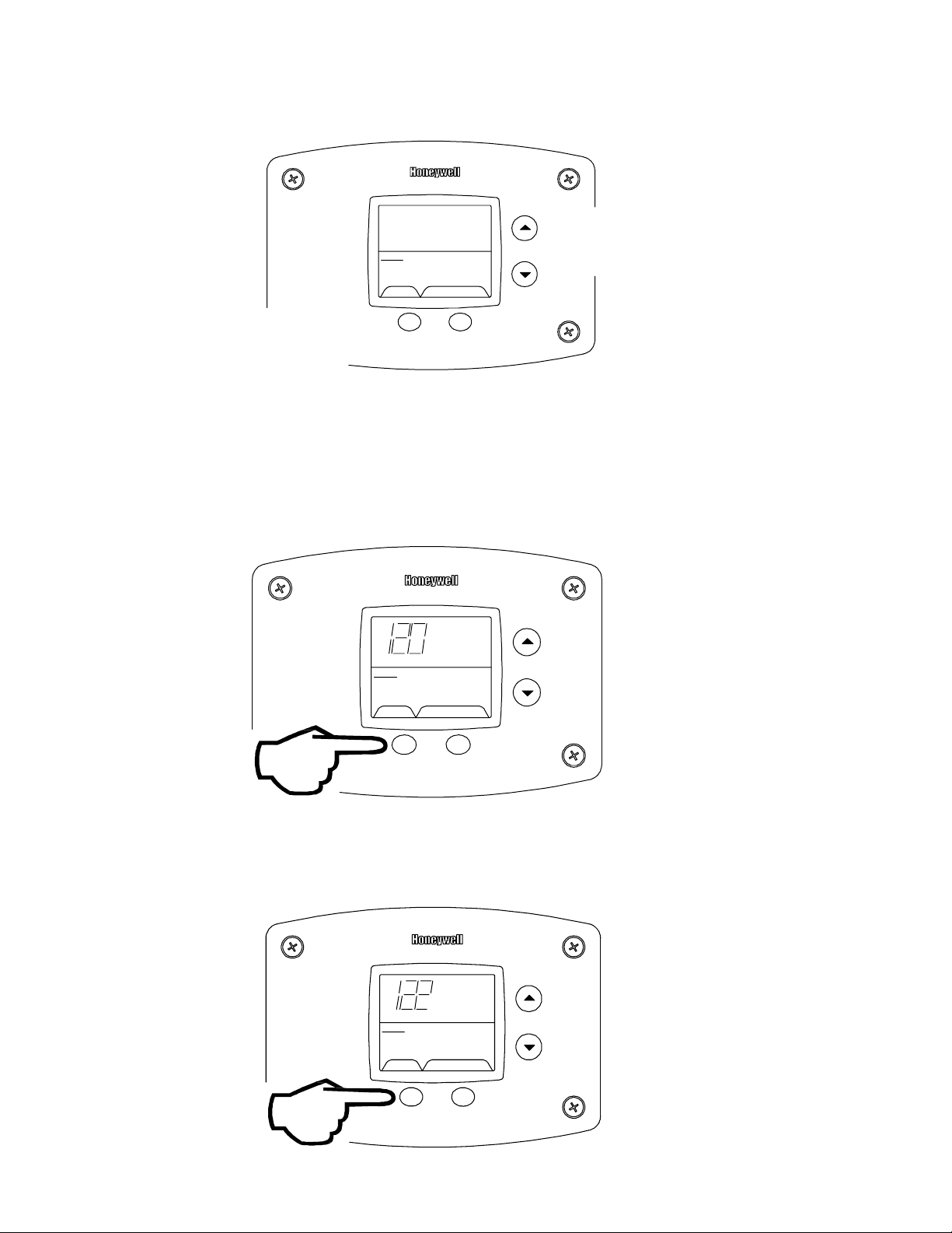
Step 5: 30 Seconds after the last button pr es s , th e Wate r Heater Dis play will go back to “User Mode”. It will read “Max
e
Setpoint” without sh owing a temperature value if the temper ature setpoint is at the maximum sett ing. The Water
Heater Display can be set back to the “User Mode” immediately by pressing both the “Temperature Up” and “Select”
buttons together for 3 seconds.
Max
Setpoint
idle
Operational
Status
SELECT SET
&
Display of Water Temperature:
Step 1: In Service Mode, Press the “Selec t” button until “Water Temp” is dis play ed in the upper right section of the
water heater display . For water heat er s usi ng two t emp erature sensors in the tank, this will be the average reading
between the two sensors. For water heaters using a single sensor, this is the reading for the sensor.
Exiting Service Mode
Water
°F
Temp
idle
Operational
Status
SELECT SET
Upper Sensor
%
Step 2: For water heaters using two t emp er ature sensors, pressing the “Se lec t” button again displays the Upper
Sensor temperature re ading. “Upper Sensor” will be display ed in the lower right side of the status window of the
water heater display.
°F
idl
Operational
Status
SELECT SET
Upper Sensor
14
Page 15
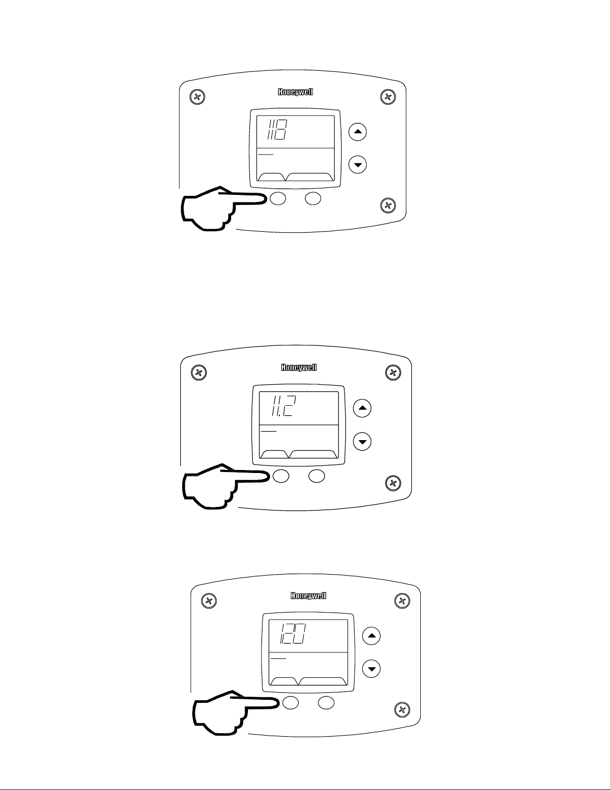
Step 3: For water heaters using two temperature sensors, press ing the “Select” button again dis play s the Lower Sensor
temperature readi ng. “Lower Se ns or ” wil l be dis play ed in the lower left side of the status window of the water heater
display.
°F
idle
Operational
Status
Lower Sensor
SELECT SET
To Display Flame Sense Current of the Pilot Flame Sensor:
The pilot flame sense current is avai lable only when the burners are in operat ion. Step 1: Make sure the status displays
“Heating” or draw enough hot water to start the burners. Step 2: Enter the “Service Mode” described previously. Step 3:
Press the “Select” button until a number value is displayed wit h “Flam e Cur r ent” to the right of the number. The value
displayed is in microamps (µA).
Flame
Current
Operational
µA
setpoint
°F
Heating
Status
SELECT SET
To Display and Change Temperature Setpoint:
Step 1: In “Service Mode” press the “Select” button until “Setpoint” is shown in the water heater display
idle
Operational
Status
SELECT SET
15
Page 16
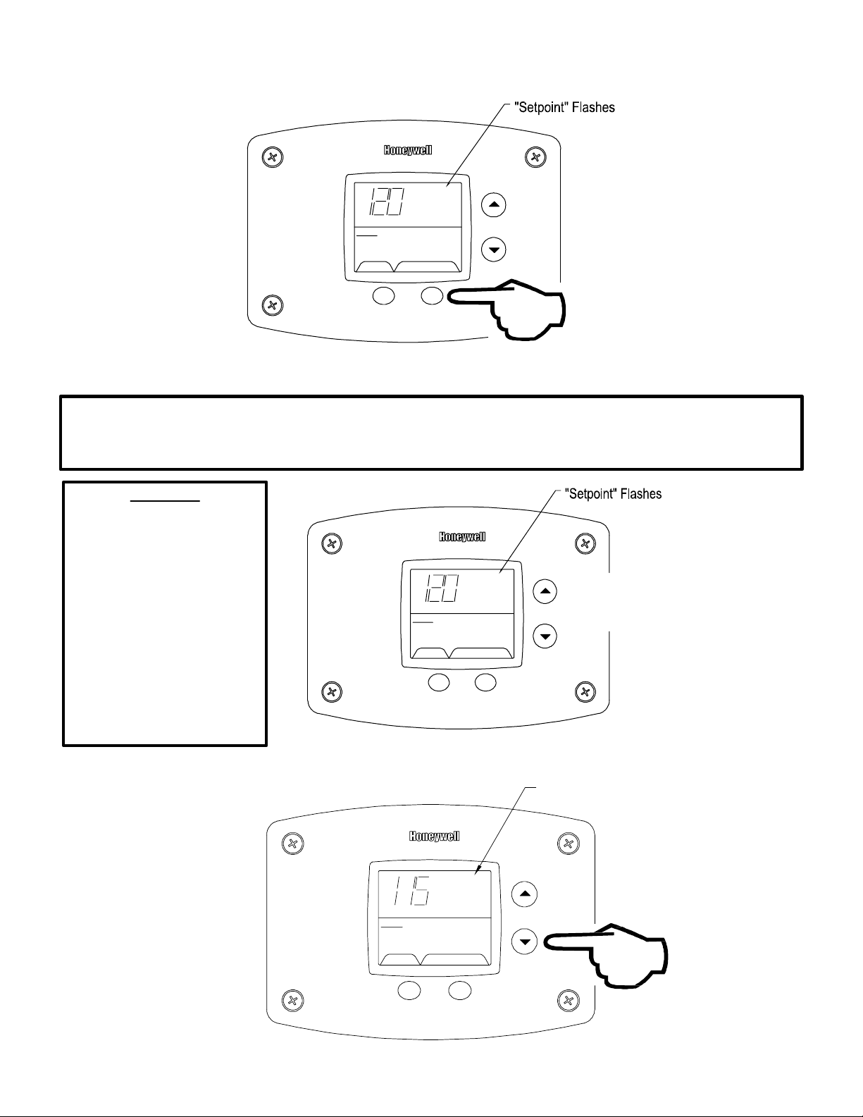
Step 2: Press the “Set” button to enter the setting mode. “Setpoint” will fl as h in the wat er heater display.
TSET
setpoint
°F
idle
Operational
Status
SELECT SET
Step 3: To raise the temperature setpoint, press the “Temperatur e Up” butt on until the desired temperatur e is sho w n on
the water heater display.
NOTICE
The maximum temperature that can be set in the Water Heater Display is limited to the “Max Setpoint” described
previously. To change the “Max Setpoint”, refer to the procedure “To Change the Maximum Setpoint Limit…"
described prev ious ly under “ Acces s ing the Service Mode on the Water Heater Display ”.
WARNING
Setting the water temperature
to the ma ximum se t point ca n
result in scalding hot water
delivered to t he faucets. It is
highly recommended that the
maximum setpoint be adjusted
to the lowest temperature
possible for the needs of the
installation. Make sure the
water heater control displa y is
not in a public ar ea that can
result in the temperature
settings being improperly
adjusted.
Step 4: To lower the temperature set point, press the “Temperature Down” button until the desired temper ature is shown
on the water heater display.
setpoint
°F
idle
Operational
Status
SELECT SET
setpoint
°F
%
"Setpoint" Flashes
idle
Operational
Status
SELEC
16
Page 17

Step 5: When the desired setpoint is reached on the water heater display, pres s the “Se t” button to confirm the new
setpoint. “Setpoin t” stops flashing in the water heater display .
setpoint
°F
idle
Operational
Status
SELECT SET
To Display and Change Temperature Format (°F/°C):
To Change Temperature Format in Display f rom °F to °C or °C to °F:
Step 1: While in “Service Mode”, pr es s “Selec t” button until “°F/°C” is shown in t he upper r ight portion of the water heater
display.
°F °F/C°
idle
Operational
Status
SELECT SET
Step 2: Press “Set” button to change temperature format. “°F/°C” symbol will flash in the water heat er dis play .
°F °F/C°
idle
Operational
Status
SELECT SET
17
Page 18

Step 3a: Press “Temperature Up” button to change temperature format to °C
°F/C°
°C
idle
Operational
Status
SELECT SET
%
Step 3b: Press “Temperature Down” button to change temperature format to °F
°F/C°
°F
idle
Operational
Status
SELECT SET
Step 4: Press “Set” button t o confir m °F or °C forma t. °F/°C wil l stop flashing
°F
°F °F/C°
idle
Operational
Status
SELECT SET
18
Page 19

Step 5: Pressing “Se lec t” button will return display to setpoint in format selected (°F or °C) immediately
°F
idle
Operational
Status
Lower Sensor
SELECT
Error Codes and Error History Display:
If there is an operating problem with the water heater, an error cod e numb er will appear on the water heater display with
“Service Needed” to the rig ht of the “Status” indicator. The error cod e label is loc ated under the Water Heater Display
and the following section in this Service Manual explains the err or code s with co rrective actions to repair th e water
heater.
SET
Example of Error Code in the Display
idle
Service Needed
SELECT
SET
Error Code History:
In “Service Mode” pressing the “Select” button after the “Software Version” (item 8 in the previous ly described sequence
of service modes) will show an error c ode his tory, if there have been any previous oper ating problems with the water
heater. If the display shows --, there is not a current error code.
The Water Heater Display will provide up to 10 previous error codes. The oldest error code will be stored in code index
#1 and the most recent in code index #10.
19
Page 20

To view previous error codes:
T
Step 1:
In “Service Mode press the “Select” button until the next display after the “Software Version”. If there are no current
error codes, the display will s how -- .
°F
idle
Operational
Status
SELECT SET
Step 2:
Press the “Temperatur e Down” butt on to select the error code index, star ting with the most recent error code “10”.
idle
Operational
Status
SELECT SE
%
Step 3:
Press the “Select” but ton to view the error code for “code 10”. If there is a number displayed, note what the number is.
The label next to the water heater display will identify the code number. If no number is displayed with onl y a “--“ in the
water heater display, then there has not been an error code for error code index 10.
idle
Operational
Status
SELECT SET
20
Page 21

Step 4:
Press the “Temperature Down ” button to change to the previous code inde x, co de #9.
idle
Operational
Status
SELECT SET
%
Step 5:
Press the “Select” button for c ode index #9 to view if there are any code numbers.
idle
Operational
Status
SELECT SET
Step 6:
Continue pressing the “Temperature Down” button to change to the next error code index and press “Select” to view the
error code number, if any, for that index num ber . Continue on to index #1, the oldest error code index. The water
heater display will stor e up to 10 erro r codes with the oldest code starting in code index #1 with the most recent code in
code index #10.
Step 7: 10 seconds after the last button pr es s , th e Wate r Hea ter Dis play will revert back to the current error co de
display. To exit Service Mode, either wait 30 seconds or press Tempera ture Up button and Select Button for 3 seconds .
setpoint
°F
idle
Operational
Statu
s
SELECT SET
%
&
Exiting Service Mode
21
Page 22

ERROR CODE DEFINITIONS
If the water heater has an operating problem, there will be a number in the water heater display with
“Service Needed” shown below the error code number. Note the error code and the def inition in the
chart below. This label appears on the control box under the water heater disp lay . The following
sections will provide instructions for servicing each error code.
22
Page 23

WARNING
The following procedure is for service and installation personnel only. Resetting lockout
conditions without correcting the malfunction can result in a hazardous condition.
If an error code is display ed (e xcept for #4, low flame sense current), the wat er heater will be in a “lockout condition”
with the water heater dis play s howing the error code number and “Servic e Needed” in the status section of the
display window. Error code s 62 (max im um number of retries detected) and 63 (maxi mu m number if ignition
recycles detected) are “Soft Lockouts” in which the control can be reset in the “User Mode” by pressing the lower
right button under “Lo ckout Reset” shown in the lower right por tion of the display. The control will also go t hr ough 3
attempts to relig ht th e bur ner s every hour in the soft lockout condition.
Status
Service needed
SELECT
Lockout RES ET
Error Code Shown in
Water Heater Display
Press for 2 seconds
%
All other error codes will put the water heater into a “Hard Lockout ” condition, in which the water heater will not
operate and cannot be res et in t he “User M ode” . To reset a hard lockout, first enter the “Se rvice Mode” described
earlier by pressing both the “Temperature Up” and “Select Buttons” at the same time for 3 seconds. Then press the
lower right butto n under “L oc ko ut Reset” in the water heater display and hold for 3 se co nds .
Resetting Error Codes in Hard Lockout Condition
Error Code Shown in
Water Heater Display
Status
SELECT SET
&
Step 1: Press for 3 seconds
to enter service mode.
Service Needed
%
23
Status
Service Needed
SELECT Lockout RES ET
Step 2: Press for 3 seconds to
reset control in service mode.
Page 24

DANGER
120 volt exposure. To avoid personal injury,
use caution while performing this procedure.
SERVICE PROCEDURE PDV24-I
Thermostat Circuit Testing
CAUTION
Be Careful When Making Voltage
Measurements or Jumping Terminals
Not to Damage or Deform Connectors or
Connector Pins.
Condition: Water Heate r Not Oper at in g
Display shows error code “31” (Upper Sensor
Readings Faulty) or error code “32” (Lower Sensor
Readin gs Fa u l ty )
Unplug or disconnect electrical power to the water heater
Check continui ty of wire h arness to affected sensor. Meas urement
of ohmeter should be close to 0 ohms. Replace wire ha rness if high
resistance is measured (over 0.5 ohms) Check wires for intermittent
connections, sho rts, frayed insulation. Replace if necessary
If wire harness checks out O.K., check sens or resista nce detailed in
the section for test ing sensor resistance. Repl ace the upper or
lower se nsor as indi cated by error code number.
Turn pow er on to water heater.
Run water heater through heating cycle and ver ify prop er operation.
Sensor temperat ure can be v iewed when burner shuts off (see
section on viewing the display in “Service Mode”.
Condition: Water Heat er Not Op erat ing
Display shows error code “65”
High Water Temperature (over 200 deg. F)
Measuring upper
sensor resistance
through wire
harness
(disconnected at
control board).
Checking
continuity of
upper sensor wire
harness.
Removing lower
sensor from well.
Held in place by a
clip fastened to
well shoulder.
WARNING
Do not reset the display from th e hard loc kou t
state without correct ing the cause of the
overheating condition
Turn power “OFF”.
Draw water to cool tank below 120 deg. F
Check lower sensor. Is the sensor fully inserted into the well?
Sensor is held in place with a clip fastened to the well (see photo )
Check lower sensor wire making sure it is not damaged or has
breaks in the wire insulati on. Check upper harne ss wires to up per
sensor , if us ed (s om e mod el s ) .
24
N
Y
If sensor clip is damaged
replace clip. Replace lower
sensor if damaged.
Check Sensor Resistance
(See Sensor Resistance
Testing, follow ing sectio n)
See next page
Page 25

Do not operate water heater without verifying that the overheating condition has been corr ected.
Condition: Water Heate r Not Oper at in g
Display shows error code “65”
High Water Temperature (over 200 deg . F)
Continued
SERVICE PROCEDURE PDV24-I
Thermostat Circuit Testing
WARNING!
Once cause of overheating condition has been diagnosed
and corrected, the control may be reset
Reconnect and sw i tch on power to t h e wa te r hea ter.
Enter se rvice mode on the water heater display (see illustration)
Press button under “Lockout Reset” and hold fo r 3 seconds.
Set thermostat to the desired setting.
Water heater should start.
Monitor temperat ures for one complete heating cycle making
sure the maximum tank temperature remains well below 200 deg. F
25
Page 26

Conditions: Upper or Lower Sensor R eading
Faulty, High Water Temperat ure, or suspect
thermostat is not accurate.
Sensor Resistance Testing
Upper Sensor
1. Determine resistan ce val ue of upper s ensor using an
ohmeter. Test across grey wire s.
2. Draw quart of water off T&P valve. Using a thermometer,
determine water temperature.
3. Use table below to verify correct resistance per water
temperature measured.
Lower Sensor:
1. Determine resistan ce val ue of lower s ens or . Test across
center wire (common) to each outside wire. Resistance of both
thermistors in the lower sens or sh ould be close to each other.
If the resistance values for both thermistors are not close to
each other, replace the lower se ns or . The dual ther m is tors ar e
used to provide high limit protec tion in case the thermostat
circuit fails to shut off the wat er heater.
2. Draw quart of water off Drain Valve. Using a thermometer,
determine water temperature.
SERVICE PROCEDURE PDV24-I
Thermostat Circuit Testing
Upper thermister location
(applicable models)
Checking resistance of
upper sensor
Lower thermister
acces s lo ca t e d ins ide
control box.
3. Use table below to verify correct resistance per water
temperature measured.
Are readings
correct?
Check harness
continuity.
Continuity okay?
Replace
control board
Example: If water temperature is 84°F, then the resistance through the sensor would be 8449 (se e shaded ar ea).
N
Y
N
Y
Replace
thermister
Replace
harness
Be Careful When Making Resistance
Measurements Not to Damage or
Deform Connectors or Connector Pins.
Sensor Resistance at Various Temperatures
NOTE: Sensor resist ance incre ases as th e temper atur e falls.
°F012345678 9
40 26109 25400 24712 24045 23399 22771 22163 21573 21000 20445
50 19906 19383 18876 18383 17905 17440 16990 16553 16128 15715
60 15314 14925 14548 14180 13823 13477 13140 12812 12494 12185
70 11884 11592 11308 11032 10763 10502 10248 10000 9760 9526
80 9299 9078 8862 8653 8449 8250 8057 7869 7685 7507
90 7333 7165 7000 6839 6683 6531 6383 6238 6098 5961
100 5827 5697 5570 5446 5326 5208 5094 4982 4873 4767
110 4663 4562 4464 4368 4274 4183 4094 4006 3922 3839
120 3758 3679 3602 3527 3453 3382 3312 3244 3177 3112
130 3048 2986 2925 2866 2808 2752 2697 2643 2590 2538
140 2488 2439 2391 2344 2298 2253 2209 2166 2124 2083
150 2043 2004 1966 1928 1891 1856 1820 1786 1753 1720
160 1688 1656 1625 1595 1566 1537 1509 1481 1454 1427
170 1402 1376 1351 1327 1303 1280 1257 1235 1213 1191
180 1170 1150 1129 1110 1090 1071 1053 1035 1017 999
190 982 965 949 933 917 901 886 871 857 842
200 828 814 801 788 775 762 749 737 725 713
Checking resistance of
lower se nsor (cen ter and
outsid e pi ns )
CAUTION
In Degrees F
26
Page 27

DANGER
120 volt exposure. To avoid personal injury,
use caution while performing this procedure.
SERVICE PROCEDURE PDV23-II
Pressure Switch Testing
CAUTION
Be Careful When Making Voltage
Measurements or Jump ing Terminals
Not to Damage or Deform Connectors or
Connector Pins.
Condition: Blower operates, burners not lit.
Display shows error code “29” (Pressure Switch
Failed to Close).
Connect a digital manometer to the tubing fo r the pres sure
switches and determ ine the aver age r eading. See t able at
right for pressure switch settings and minimum readings
required. Is the p ressure swit ch reading at least 0.20 "
above the swit ch reading for the model tested ( s ee chart at
right)?
Check intake and ex haust vent terminals out side the
building. Is there any blockage from debris (leaves, ice,
snow, paper, etc.). If so, clear intake or exhaust vent
termin als. Pressur e switch sh ould close an d the burner s
should fire.
Check the total equivalent vent length by adding up the
total number of elbows and th e str aight lengths of vent pipe
for the intake and exhaust pipe (or coaxial vent pipe for
PDV-T model se ries). See table at right f or maximum
distances. If the venting distance is excessive, reduce the
number of elbows or route the vent ter minals to a shorter
distance outside the building.
If the vent ing system a nd vent termi nals are O.K. , but the
pressure switch reading is still low, check the pressure
switch tubi ng to make sure there are no small holes or
kinks. Make su re there are n o drops of cond ensate in t he
tubing. Check the pressure switc h tubing connection fitting
and pressure tap to make sure it is not clogged with dirt.
Blow through tubing to verify that the pressure taps and
tubing are clear and not leaki ng.
Minimum Differential Dual Tap Pressure Switch Settings:
(Contacts open)
PDV80S,100S-150 models: -2.00" w.c.
PDV80S,100S-200 models: -1.20" w.c.
PDV80S,100S-250 models: -2.00" w.c.
PDV80T300 models: -1.20" w.c.
PDV100T360 models: -0.60" w.c.
Note: During normal hot running conditions, the
pressure switch readings shou ld be at least 0.20 " higher
than the above readings where the pressure switch will
open.
PDV80,100S-150,200 Mod els with 3" PVC vent: Maximu m
Distance of 40 feet with one 90 deg. elbow for intake or
exhaust (subtract 5 feet for each additional elbow).
For venting with 4" PVC vent: Maximum distance of 55 feet
with one 90 deg. elbow for intake or exhaust (subtract 5
feet for each additional elbow).
PDV80S,100S-250 Mod els with 4" PVC ven t: Maximum
distance of 55 feet with one 90 deg. elbow for intake or
exhaust (subtract 5 feet for each additional elbow).
PDV80T300, PDV100T360 Models with coax ial vent ing
system: Maximum venting distanc e of 19 feet 6 inches
with one 90 deg. elbow. Each additional elbow reduces
the venting distance by 39".
See installation instruction manual s supplied with the
water heater for further details on proper venting
installations.
PDV-S MODELS: Check the vent safety thermal switch
near the outlet of t he blower (see photo at right) . Press the
red reset button. (See photo on next p age). If you feel a
slight click, the t emperature was excessi ve and the switch
opened. C heck t o be sure the bur ner acces s screws are
tight and the gasket is in good condition (see section on
servicing the burner s)
If the pressure switch readings are at least 0.20" w.c.
above the ab ove pressure s witch setti ngs for the installed
model an d the swi tch does n ot close, then repla ce the
pressure switch with the same setpoint.
Checking pressure switch contacts.
Contacts are open if blower is
operating and there is 22-26 volts
measured between the two contact s
(as in photos)
27
Page 28

DANGER
120 volt exposure. To avoid personal injury,
use caution while performing this procedure.
PDV(S & T) Models Vent Safety Switch (PDV-S Models Only)
Red reset button
SERVICE PRO C EDURE PDV24-II
Pressure Switch Testing
CAUTION
Be Careful When Making Voltage
Measurements or Jumping Terminals
Not to Damage or Deform Connectors or
Connector Pins.
Check pressure switch tubing to the pressure switch. Make
sure tubing does not have kinks, holes, condens ate, or dirt
blocking air pressure to the switch. The tubing to the
blower tap attaches to the - (minus) tap on the pressure
switch.
Induced Draft Models (D80T725 & D65T625):
Vent safety thermal switch on PDV-S blow er. Depress red
reset button in center of switch . If a slight click is felt, switch
opened. Check for loose or leaking burner access panel (se e
section on servicing burne rs)
Induced Draft Models use a single tap pressure switch to
measure vacuu m in the flue collect or. The pressure
switch is located inside the control box (see photo to left).
Connect a digital manometer to a tee in the pressure
switch tubi ng and measure t he vacuum wit h the blower
operating. The vacuum should be in the range of -1.70"
to -2.10" w.c. The pressure switch contacts will open at
-1.25" and close by -1.40" w.c. If the vacuum is below -
1.50", check to make sure the fl ue damper is fully open
when the blower is operating. Make sure the damper and
rod are not binding. Make sure there are no restrictions
in the venting system and that is at least 8" in diameter.
Venting is for vertical gravity venting only. Insure that
there is sufficient combustion air to the utility room.
28
Page 29

DANGER
120 volt exposure. To avoid personal injury,
use caution while performing this procedure.
Condit i on: Blowe r do e s no t op er a te , burners not lit.
Display shows error code “29” (Pressure Switch
Failed to Close ).
With a voltmeter, check to make sure the “line in” connection
to the control bo ard has 11 0-120 volt s. Make sur e the
secondary plug from the transformer to the board has 24
volts at the yellow and blue wire pin terminals (see photos to
right).
Make sure the water heater control display shows “Heating”
in the status window. Raise the setpoint if needed. If there
is no call for heat and the setpoint is well above the tank
temperature, refer to the thermostat troubleshootin g and
replacement section.
If the water heater control display sho ws “Heating” and the
blower is off, Error code 29, then check the voltage output at
the blower plug on the board. Should read 110-120 volts
between the black and white wires to the blower (terminals 5
and 3 on the inducer output on the control board, see
illustration to the right).
If there is voltage between the black and white wires to the
blower plug on the board, then check the voltag e at the
blower connection on the blower (se e photo at right). If no
voltage is present, replace the wire harness. If there is 110120 volts, replace the blower.
SERVICE PRO C EDURE PDV24-II
Pressure Switch Testing
CAUTION
Be Careful When Making Voltage
Measurements or Jumping Terminals
Not to Damage or Deform Connectors or
Connector Pins.
Checking line voltage to board.
Pins to black and white wires.
Checking secondary
voltage from transformer.
Pins to blue and yellow
wires.
Condit i on: Blowe r do e s no t op er a te , burners not lit.
Display shows error code “2” (Pressure Switch
Failed to Open - Stuck Closed).
Disconnect power and remove the pressure switch cover
(previous phot o-PDV models). Disco nnect wires on the
pressure switch. Measure continuity on the pressure switch
terminals with an ohmeter. If there is continuity, the pressure
switch is stuck closed. Make sure pressure switch has not
been bypassed (jumpered). The control will not operate with
a jumpered pressure switch.
If press ure switch contacts ar e stuck clos ed, check t he
pressure switch tubing for conde nsate, dirt, or kinks. If the
tubing is O.K., replace the pressure switch with the same
setting.
Reconnect power. Verify
proper operation.
If there is no voltage on the contr ol boar d to t he blower
plug and the control display shows “Heating”, then
replace the contr ol boar d.
Checking line voltage at the
blower wire harness connection
on blower.
29
Page 30

DANGER
120 volt exposure. To avoid personal injury,
use caution while performing this procedure.
Condition:
Pilot will not light or stay lit,
Error codes 62, or 63 shown on Water
Reset control by pressing the lower
display for 3 seconds. Does control
board start ignition sequence and
start sparking (sparking noise at pilot
Heater Display
right butt o n un de r “re s et” on the
or at boar d)
N
Replace control board
SERVICE PROCEDURE PDV24-III
Pilot Operation Testing
CAUTION
Be Careful When Making Voltage
Measurements or Jumping Terminals
Not to Damage or Deform Connectors or
Connector Pins.
Checking for 24
volts output to
pilot valve
(yellow an d red
wire pin
terminals on
control board
“con trol” plug.
Y
Is there spark at the pilot?
Y
Is there 22-27 volts AC out put across
terminal pins 8 & 2 on “Control” plug
of Contr ol B o ard ? Care fu ll y ins ert
meter probe in wire plug to check pin
terminals. Make sure control is in the
trial for igni tion sequen c e (se e
sequence of operation).
(see photo at top of page)
Y
Is there 22-27 volts AC input across
wire leads
“MV/PV” & “PV”
at Gas Valve?
(see ph oto to the right)
N
Check wire harness for damage or
loose connections. Repair or replace
as needed.
Turn on power to t he water heater
and verify proper operation
N
N
Y
Loose or damaged ignition wire
Loosen pilot tubing connection at
the gas va lv e and soap test.
Is there pilot gas flow out of the
gas valve? See pilot illustration
Tighten pilot tube connection at
the gas valve. Check incoming
gas pres su r e to water heat e r. if
Checking MV
pin terminal to
gas valv e w ire
harness for 24
volts output to
gas valv e du r in g
heating cycle
(pilot must be lit
with no
sparking).
Check for:
Grounded pilot electrode
Damaged pilot.
Replace control board.
Y
for pilot inspe ct io n.
N
okay, replace gas valve
Check across “MV/PV” & “PV” Wire
leads to gas valve
Check for clogged or kinked pilot
tube, clogged pilot orif ice. Clean
or replace as needed.
(see pho to below)
Pilot
Orifice
7//16"
ferrule
Nut
Aluminum
Pilot Tubing
Flame
Rod
Ceramic
Insulators
Ignition
Wire
Flame Sense
Wire
30
Page 31

SERVICE PROCEDURE PDV24-III
Pilot Operation Testing
Error code 57: Flame Rod Shorted
Condition:
to Ground
Disconnect power. Shut off gas
supply to water heater. Slide out
burner assembly. See section on
removing pilot and main burner
assembly.
Make sure pilot shield
clears flame sense rod
Check to see if pilot shield is touching
pilot flame sensor or flam e sensor
touching pilot hood. Bend shield to
prevent interference.
Check pilot flame sense wire for
broken insulat ion. Replace pilot if
defective
Reinstall pil ot and burner assembl y .
Reconnect gas li ne union, turn on
gas. Reconnect power and verify
proper ignitions.
31
Page 32

DANGER
120 volt exposure. To avoid personal injury,
use caution while performing this procedure.
SERVICE PROCEDURE PDV24-III
Pilot Operation Testing
CAUTION
Be Careful When Making Voltage
Measurements or Jumping Terminals
Not to Damage or Deform Connectors or
Connector Pins.
Pilot lights, no or low flame signal. Control
Condition:
Display shows “4” or “62” for Error Codes
(Service Needed) . C ontrol continues to spark
until system “Lock Out”.
Main burner will not light.
Check for loose or damaged flame sense
lead from pilot to module. (see illustration to
the right). Is flame sense lead okay?
Y
Check for loose or damaged ground wire(s)
from gas valve to control board. Check
continuity of wires with ohmeter. Are ground
wires okay?
Y
Check ve nting conditions
(vent length & number of el bows)
Is vent system okay?
Y
Is heater condensing causing pilot
interruption?
N
The microamp output of the pilot may be
checked by entering “Service Mode” on the
water heater display and pressing “Select”
until the flame current is shown. The control
must be in the heating mode with the pilot lit
to display a reading. See section on
accessing service mode on the water heater
display.
Meter
Heating
Status
SELECT
Probe
Operational
Flame rod
µA
Flame C urr ent
SET
N
N
N
Y
Repair wire lead
or replace pilot.
Repair ground
wire(s) or replace
as needed.
Correct improper
venting condition.
Make s ure pilot shield is in
place an d not bent or damaged
(refer to secti on on main burner
and pilot assembly) .
Determ ine cause for
condensing and correct.
Under sized water heater or
high demand periods
NOTE:
Check co ntinuit y of fla m e sense
lead to flame rod . If no
conti nu ity, clean pilot flame rod
or replace pilot. Check pilot
flame appearance - if weak
check f or clogged pilot orifice,
bent pilot tubing, or low inlet
gas pressure.
(see ab ov e ill us tr a tion)
Multi-m e ter se t
to check
continuity.
Meter
Probe
Checking pilot flame sensor wire and flame
rod for con tin uity.
Pilot f lame sensor microamp output
shown in display using service mode.
Pilot must be lit to get reading.
Micro-amp readings
0.000 Micro Amp = Replace control board or pilot if w ire is
damaged.
1.0 micro amp or less = Clean pilot flame rod or re place pilot.
32
Page 33

DANGER
120 volt exposure. To avoid personal injury,
use caution while performing this procedure.
Condition:
Display shows “Heat ing” under temperat ure
Main burner will not light,
setpoint.
Tank is cold.
Is Pilot lit?
Y
Does control board continue to spark wi th
pilot lit?
See “pilot will not light”
N
Y
in “Pilot Opera tion
Testing” section.
See “Pi lot lights, no flame signal” in
“Pilot Operation Testing” section.
SERVICE PROCEDURE PDV24-IV
Main Burner Operation Testing
CAUTION
Be Careful When Making Voltage
Measurements or Jumping Terminals
Not to Damage or Deform Connectors or
Connector Pins.
Checking MV & MV/PV control plug
pins to gas valve for 24 volts output
during heating cycle (pilot must be
lit with no sparking).
N
Disconnect control wire harness from
“Control” plug of control board.
Is there 22-27 volts AC across
pin terminals 5 & 8? Refer to wi ring
diagram
(also see photo )
Y
Reconnect control plug
to control board.
Disconnect brow n wire lead from
“MV” terminal of gas valve.
Is there 22-27 volts AC across
brown wire lead & ground
N
Check wire harness for damage or loose
connect ions. Repair or replace as needed.
NN
Y
Be sure control display is showing “Heating”,
pilot is lit and cont rol is not sparking .
Recheck voltage across control board
pin terminals 5 & 8 ((MV & MV/PV)
Is voltage present?
Y
Brown wire disconnected
from “MV” terminal of gas
valve
Check incoming gas
pressure to gas valve. if
okay,
replac e ga s valve.
Replace control board.
Ground lug of
gas valv e
33
Checking main valve (MV) volt age to gas va lve.
Page 34

DANGER
120 volt exposure. To avoid personal injury,
use caution while performing this procedure.
SERVICE PROCEDURE PDV24-IV
Main Burner Operation Testing
CAUTION
Be Careful When Making Voltage
Measurements or Jumping Terminals
Not to Damage or Deform Connectors or
Connector Pins.
Condition:
Main burner short cycles.
Contr ol D is pl ay may show err o r
code “63, 57, or 4” and be in
“Soft Lockout” state.
Check gas (line) pressure to the
water he ater.
Minimu m line pressure should be
5.5" W.C.
Is gas pres sure within proper
specif ication? (see photo at right)
Y
Check venting conditions.
(blocked intake or exhaust
termina l, excessive vent lengt h,
or number of elbow s )
Verify pressure sw itch is not
cycling (see “Pressure Switch
Testing”.
Is vent system okay?
Y
Is there sufficient combustion air
being supplied to the water
heater?
Y
Determ ine cause of
N
pressure and correct.
N
N
Correct improper
venting condition.
PDV(S&T) MODELS : Check
intak e piping and terminal.
INDUCED DRAFT MODELS:
Make sure there is sufficient
air supply to utility room.
Line gas
pressure port
incor rect gas
Manifold
Pressure Port
Connect hose barb to manifold
pressure port, then connect
monometer to measure gas manifold
pressure.
Check for unstable pilot flame or oxidized
flame rod on pilo t causing w eak pilot
signal. Make sure pilot shield is in place
and does not touch pilot flame sensor.
(see “pilot inspection”)
Check burner tube s for scale or
debris build-up. Clean burner(s)
as necessary.
(see “main burner inspection”)
Check tank flues for blockage or
debris build-u p causing
restriction.
(see “flue baffle inspection”)
34
Page 35

SERVICE PROCEDURE PDV24-V
Main Burner & Pilot
Removal and Inspection
WARNING
Water Heater components may be HOT when performing the following steps in this
procedure. Take necessary precaution to prevent personal injury.
PDV (S&T) MODELS
Step 1: Remove burner box cover screws
PDV-S MODELS
(Hinged Door)
PDV-T MODELS
(Removable Door)
Step 2: Open Burner Box Cover
Step 3: Disconnect Pilot Fit ting from
Burner Box
Step 5: Disconnect and Remove Gas
Valve
Step 4: Disconnect gas valve wir es and
pilot tube
Step 6: Remove pipe flange plate from
Burner Box
35
Page 36

SERVICE PROCEDURE PDV24-V
Main Burner & Pilot
Removal and Inspection
WARNING
Water Heater components may be HOT when performing the following steps in this
procedure. Take necessary precaution to prevent personal injury.
PDV (S&T) MODEL S
Step 7: Remove manifold bracket screws
Step 9: Slide manifold out through side
flange opening in Burner Bo x
PDV-S MODELS
Step 8: Remove manifold from Bu rn er s
Step 10: Disconnect Pilot Tube Fitting
from inside Burner Box
PDV-T MODELS
Step 11: Remove screw fastening burner
to burner box/burner shr oud.
Step 12: Disconnect Pil ot wires from
control board and remov e from Control
Box
36
Page 37

SERVICE PROCEDURE PDV24-V
Main Burner & Pilot
Removal and Inspection
WARNING
Water Heater components may be HOT when performing the following steps in this
procedure. Take necessary precaution to prevent personal injury.
PDV (S&T) MODEL S
Step 13: Pull pilot wires through burner
box
Step 15: To remove pilot, remove pilot
bracket screws
Step 14: Slide out burner as s em bly
Step 16: Slide pilot assembly to back of
burner rack
Step 17: Pilot removal for servicing.
37
Page 38

SERVICE PROCEDURE PDV24-V
Main Burner & Pilot
Removal and Inspection
WARNING
Water Heater components may be HOT when performing the following steps in this
procedure. Take necessary precaution to prevent personal injury.
INDUCED DRAFT MODELS
Gas Valve
Contr ol Knob
Main Burner Removal
Gas Valve
Step 1. Disconnect (un-plug) water heater from
electric al s upply .
Step 2. Turn “OFF” gas supply to water heater.
Step 3. Rotate gas valve control knob to the “OF F” pos ition
(see photos at right).
Wire Lead s
Burner Rack
Mounting
Screw
Step 4. Disconnect Gas supply line from the gas valve.
Step 5. Disconnect wire leads from gas valve
(see photos at right).
Pilot Flame Sense
Wire (White)
Step 6. Disconnect white flame sense wire & orange ignition
wire from Control Board (see photos at right).
Step 7. Remove the two burner rack mounting screws (see photos).
Step 8. Slide complete burner rack out from water heater
(see photos below).
Step 9. To install burner, reverse above pr oc edure.
Step 10. Check for gas leaks and verify proper operation.
Burner Rack
Mounting
Screw
Pilot spark wire
(Orange)
Pilot Draft
Shield
38
Page 39

PDV (S&T) AND INDUCED DRAFT MODELS
Pilot Burner Removal
Step 1. With burner rack removed from heater, disc onnect
pilot tube connect ion from gas val ve
Step 2. Remove the two pilot burner mounting screws
securing the pilot and pilot sh ield in place.
Step 3. Remove pilot shield and pilot from burner rack.
Step 4. To install pilot burner and pilot shield, reverse above
procedure. Be sure to reconnect green ground wire.
SERVICE PROCEDURE PDV24-V
Main Burner & Pilot
Removal and Inspection
Pilot Shield
Pilot Burner Inspection
Step 1. Inspect pilot for the following:
a) Broken or cracked ceramic ins ulators. If found,
pilot must be replaced.
b) Damaged electrode or flame s ens e wir e. If found,
pilot must be replaced.
c) Oxidation build- up on flame rod. Clean flame rod
or replace pilot as necessary.
Step 2. Inspect pilot orifice:
a) Remove 7/16" ferrule nut from bottom of pilot.
b) Remove pilot tube and orific e from pilot.
c) Inspect pilot tube for blockage. Clean or replace
as necessary.
d) Inspect pilot orifice for blockage. Clean or replace
as necessary.
Pilot & Pilot Shield
Mounting Screws
Pilot
Orifice
7//16"
ferrule
Nut
Ground Wire
Location
Flame
Rod
Ceramic
Insulators
Ignition
Wire
Flame Sense
Wire
Aluminum
Pilot Tubing
39
Page 40

SERVICE PROCEDURE PDV24-VI
Control Board Replacement
DANGER
120 volt exposure. To avoid personal injury,
unplug while performing this procedure.
Depress
plastic
tabs
Control board re pl a cement
Step 1. Depress left plastic tabs and
pull out from slots in contro l panel
Slots in
control panel
Unhook tabs
from control
panel slots
Step 2. Tilt control panel to the
right and slide control hook tabs
from slots in control panel.
Step 3. Unplug wire connections from board and replace.
Wire connections
Remove lower sensor
Remove clip, pull sensor out.
Remove clip
Pull out sensor
40
Page 41

SERVICE PROCEDURE PDV24-VII
Flue Baffle Removal, Inspection
WARNING
Heater components may be HOT when performing the following steps in this procedure.
Take necessary precaution to prevent personal injury.
Step 1. Disconnect (unplug) water hea ter from elec trical supply.
Step 2. Turn “OFF” water supply to water heater .
Step 3. Open a near by hot water faucet to relieve tank pressur e.
Step 4. Connect hose to drain valve of water heater and route to an open
drain. Open drain valv e and dr ain a minimum of 5 gallons of water
from the water heate r. Clos e dr ain v alv e and dis c onnect drain hose
from water heater.
Step 5. If required, disconnect top plumbing connection from top of water heater.
Step 6. Remove screws holding jacket head to top of water heater
and remove jacket head from top of water heater. Note, it may
be necessary to use a screw driver to pry underneath
jacket head.
Step 7. If required, remove insulation from top of water heater to expose
collector cover.
Step 8. Remove screws from top (or side) of collector cover. Note, it may be
necessary to chisel away some foam to access screws.
Step 9. Remove collector cover from water heater.
Step 10. Remove flue baffl es from water heater. Note, it may be necessary
to use pliers to loosen and remove baffles from flue tubes.
Step 11. Visually inspect flue baffles. Flue baffles m ay show signs
of oxidation; thi s is normal. If the oxidation has deteriorated
any portion of the flue baffle, replacement is recomm ended.
If any restrictors are missing, replacement is recommended.
Step 12. Upon completion of inspection or subsequent replacement,
reinstall flu e baff les into heater.
Step 13. Reinstall collector cover and insulation ( if applicable)
over collector cover.
Step 14. Reinstall jacket head.
Flue Baffle
PDV Models
Step 15. Reconnect plumbing connection to top of water heater
& turn on water supply if required.
Step 16. Check for leaks and verify proper oper ation.
41
Page 42

SERVICE PROCEDURE PDV24-VIII
Anode Removal and Inspection
WARNING
Water Heater components may be HOT when performing the following steps in this
procedure. Take necessary precaution to prevent personal injury.
Step 1. Disconnect (unplug) water heater fr om elec tric al supply.
Step 2. Turn “OFF” water supply to water heater.
Step 3. Open a near by hot water faucet to relieve tank pressure.
Step 4. Connect hose to drain valve of water heater and ro ute to an open drain. Open
drain valve and drain a minimum of 5 gallons of water from the water heater.
Close drain valve and disconnect drain hose from water heater.
Step 5. If required, disconnect top plu mbi ng co nnec tion from top of water heater.
Step 6. Remove screws holding jacket head to top of wate r heater
and remove jacket head from top of water heater. Note, it may
be necessary to use a screw driver to pry und er neath
jacket head (see photos at right).
Replace Anode
Step 7. Remove insulation from top of water heater to expose collector cover,
if necessary. (see bottom of page for approx. anode locations )
Step 8. Remove screws from top (or sides) of collector co ve r. Note, it may be
necessary to chisel away some foam to access screws.
Step 9. Locate and remove anode rods from top of water heat er (1-1/16 hex socket).
Step 10. Visually inspec t anode rod. Anode rod may show signs of depletio n;
this is normal. If the anode shows signs of depletion
(approximately 5/8", see photo at right), replacement is recommended. If any of
the steel core of the anode is expos ed, replacement is recommended.
Step 11. Upon completion of inspection or subsequent replacement,
reinstall anode rods into wat er heater.
Step 12. Check for leaks.
Step 13. Reinstall collector cover & insulation over coll ec tor c ov er , if applicable.
Step 14. Reinstall jacke t head.
Step 15. Reconnect plumbing con nection to top of water heater if required.
Step 16. Restore water supply and power to water heater.
Step 17. Verify proper operation.
42
Page 43

Generic Parts List
PDV-S
1A. Vent Kit
2A. Vent Elbow
3A. Intake Termin a l
4A. Vent Reducer
5A. PVC Pipe
6A. Blower Vent Adaptor
7A. Blower Receptacle Gasket
8A. Blower
9A. Temperature Switch
10A. Blower Intake Gasket
11A. Blower Mounting Flange
12A. ¼-20 Hex Nut
13A. Collector to Blower Transition
14A. Air Intake Assembly
15A. Utility Cover
16A. Air Intake Pipe
17A. Cover Rear Boot
18A. Combustion Box Boot
19A. Blower Escutcheon
20A. Blower Hose Barb
21A. Air Inlet
22A. Vent Orifice
23A. Air Intake Tee
24A. Cold Water Inlet Dip Tube
25A. Hot Wa ter Outlet Nipple
26A. Pressure Switch Cover
27A. Pressure Switch
28A. Flue Baffle
29A. Hex Head Anode
30A. Pipe Plug
31A. Hole Closure
32A. Hot Wa ter Outlet Nipple
33A. Lower Thermostat Well
34A. Wire Harness Lower Sensor
43
35A. T & P Nipple
36A. T & P Valve
37A. Cold Water Inlet Nipple
38A. Drain Valve
39A. Sight Glass Holder
40A. Sight Glass Gasket
41A. Sight Glass
42A. Combustion Box Gasket
43A. Combustion Box Gasket
44A. Cleanout Gasket
45A. Cleanout Cover (Tank)
46A. 5/16-18 Hex Screw
47A. Cleanout Cover (Jack et)
48A. Lower Thermostat Sensor Clip
49A. ASSE Approved Mixing Valv e
50A. Blower Harness
51A. Pressure Switch Harnes s
Page 44

Generic Parts List
PDV S
1B. Gas Va l ve Assembly
2B. Burner Assembly
3B. Burner Rack
4B. Burner Tube
5B. Burner Shroud
6B. Burner Draft Panel
7B. Burner Support
8B. Aluminum Tubing
9B. Pilot Shield
10B. Pilot Orifice
11B. Pilot Assembly
12B. Street Elbow
13B. Gas V a lv e
14B. Aluminum Tubing
15B. Nipple Close
16B. Union
17B. Nipple
18B. Combustion Box Flange
19B. Flange Gasket
20B. Manifold
21B. Main Burner Orifice
44
Page 45

Generic Parts List
PDV-S
1C. Control Box Assembly
2C. Control Box Cover Assembly
3C. Honeywell Display
4C. Control Box Cover
5C. Integrated Cont r ol B oar d
6C. Control Box Panel
7C. Power On/Off Switch
8C. Pan Head Screw w/adh.
9C. Pan Head Screw #8-18
10C. Transformer
11C. Strain Relief Bushing ½"
12C. Strain Relief Bushing 7/8"
13C. Snap-In-Bushing 7/8"
14C. Power Cord Wiring Harness
15C. Display Control Wiring Harness
16C. Display Cover Wiring Harness
17C. Primary Transfor m er Wiri ng Har nes s
18C. Secondary Transformer Wiring Harness
19C. Gas Valve Control Wiring Har nes s
20C. Pan Head Screw #8-18.
21C. Ground Lug
22C. Snap-In-Plug 7/8"
45
Page 46

Generic Parts List
PDV-T
1A. ASSE Approved Mixing Valve
2A. Vent Clamp
3A. Blower Vent Adapter
4A. Combustion Box Cover
5A. Wire Raceway
7A. Blower Receptacle Gasket
8A. Blower
9A. Temperature Switch
10A. Blower Intake Gasket
11A. Blower Mounting Flange
12A. ¼-20 Hex Nut
13A. Collector to Blower Transition
15A. Utility Cover
16A. Air Intake Pipe
18A. Combustion Box Boot
19A. Blower Escutcheon
20A. Blower Hose Barb
24A. Cold Water Inlet Dip Tube
25A. Hot Wa ter Outlet Nipple
26A. Pressure Switch Cover
27A. Pressure Switch
28A. Flue Baffle
29A. Hex Head Anode
30A. Upper Thermostat Sensor
31A. Upper Sensor Wire Harness
32A. Hot Wa ter Outlet Nipple
33A. Lower Thermostat Sensor
34A. Lower Sensor Wire Harness
46
35A. T & P Nipple
36A. T & P Valve
37A. Cold Water Inlet Dip Tube
38A. Drain Valve
39A. Combustion Box Gasket
40A. Combustion Box Gasket
41A. Cleanout Gasket
42A. Cleanout Cover (Tank)
43A. 5/16-18 Hex Screw
44A. Cleanout Cover (Jack et)
Page 47

Generic Parts List
PDV T
1B. Burner Assembly
2B. Burner Rack
3B. Burner Tube
4B. Burner Draft Panel
5B. Burner Support
6B. Aluminum Tubing
7B. Pilot Shield
8B. Pilot Orifice
9B. Pilot Assembly
10B. Manifold
11B. Main Burner Orifice
12B. Gas Valve Assembly
13B. Nipple
14B. Street Elbow
15B. Union
16B. Nipple Close
17B. Aluminum Tubing
18B. Gas V a l ve
47
Page 48

Generic Parts List
PDV-T
1C. Control Box Assembly
2C. Control Box Cover Assembly
3C. Honeywell Display
4C. Control Box Cover
5C. Integrated Cont r ol B oar d
6C. Control Box Panel
7C. Power On/Off Switch
8C. Pan Head Screw w/adh.
9C. Pan Head Screw #8-18
10C. Transformer
11C. Strain Relief Bushing ½"
12C. Strain Relief Bushing 7/8"
13C. Snap-In-Bushing 7/8"
14C. Power Cord Wiring Harness
15C. Display Control Wiring Harness
16C. Display Cover Wiring Harnes s
17C. Primary Transfor me r Wir i ng Har nes s
18C. Secondary Transformer Wiring Harness
19C. Gas Valve Control Wiring Harness
20C. Pan Head Screw #8-18.
21C. Ground Lug
22C. Snap-In-Plug 7/8"
23C. Upper Sensor Harness
48
Page 49

Generic Parts List
INDUCED DRAFT MODELS
1A. Flue Ba ffle
2A. He x H ead An o de
3A. Pr essur e Tap Fittin g
4A. 1/8" NPT Elbow
5A. Ho s e B arb
6A. Silicone Hose
7A. Control Box Assembly
8A. ASSE Approved Mixing Valve
9A. Blower Transistion
10A. T & P Nipple
11A. T & P Valve
12A. Hot Water Outlet Nipple
13A. Blower Flange Mou nt
14A. Vent Adapter
15A. Flange Gasket
16A. Blower
17A. Drain Valve
18A. Co ld Wa te r In l e t Di p Tu b e
19A. Cleanout Gasket
20A. Cleanout Cover (Tank)
21A. 5/16-18 Hex Screw
22A. Cleanout Cover (Jacket)
23A. Upper Thermostat
24A. Lower Thermostat Well
25A. Lower Thermostat Clip
26A. Lower Thermostat Sensor
27A. Utility Cover
28A. Burner Assembly
49
Page 50

Generic Parts List
INDUCED DRAFT MODELS
1B. Burner Assembly
2B. Burner Panel
3B. Burner Tube
4B. Burner Mounting Bra cket
5B. Burner Rack
6B. Dual Gas Valve Assembly
7B. Main Burner Orifice
8B. Manifold
9B. Pilot Assembly
10B. Aluminum Tubing
11B. Pilot Draft Shield
12B. Burner Support
13B. Valve Support Bracket
14B. 1" NPT Street Elbow
15B. 1" NPT X 3-½" Nipple
16B. 1" NPT Elbow
50
Page 51

Generic Parts List
INDUCED DRAFT MODELS
1C. Control Box Assembly
2C. Control Box Cover Assembly
3C. Pan Head Screw #8-18
4C. Honeywell Display
5C. Control Box Cover
6C. Integrated Cont r ol Bo ar d
7C. Pan Head Screw #8-18
8C. Transformer
9C. Ground Lug
10C. Pressure Switch
11C. Power On/Off Switch
12C. Control Box Panel
13C. Secondary Transformer Wiring Harness
14C. Primary Transformer Wiring Harness
15C. Strain Relief Bushing ½"
16C, Strain Relief Bushing 7/ 8"
17C. Snap-In-Plug 7/8"
18C. Pan Head Screw w/adh.
19C. Blower Wiring Harness
20C. Power Cord Wiring Harness
21C. Gas Valve Control Wiring Harness
22C. Upper Sensor Harness
23C. Display Control Wiring Harness
24C. Display Cover Wiring Harness
51
Page 52

AC Alternating Current
BTU/H British Thermal Units
CO Carbon Monoxide
CO2 Carbon Dioxide
DC Direct Current
ECO Energy Cut Off
GFI Ground fault interrupt
GPM Gallons per Minute
Hz Hertz
LED Light Emitting Diode
NOx Oxides of Nitrogen
NPT National Pipe Thread
PSI Pounds per Square Inch
VA Volt Amps
VAC Volts Alternating Current
W.C. Inches of Water Column
°C Degrees Centigrade
°F Degrees Fahrenheit
µA Micro Amp
Glossary of Terms
NOTES
52
 Loading...