

Page 1
Instructions for:
TTW 1 Universal Service
Replacement Blower Kit
P/N 265-47200-00
(To be performed ONLY by qualified service providers)
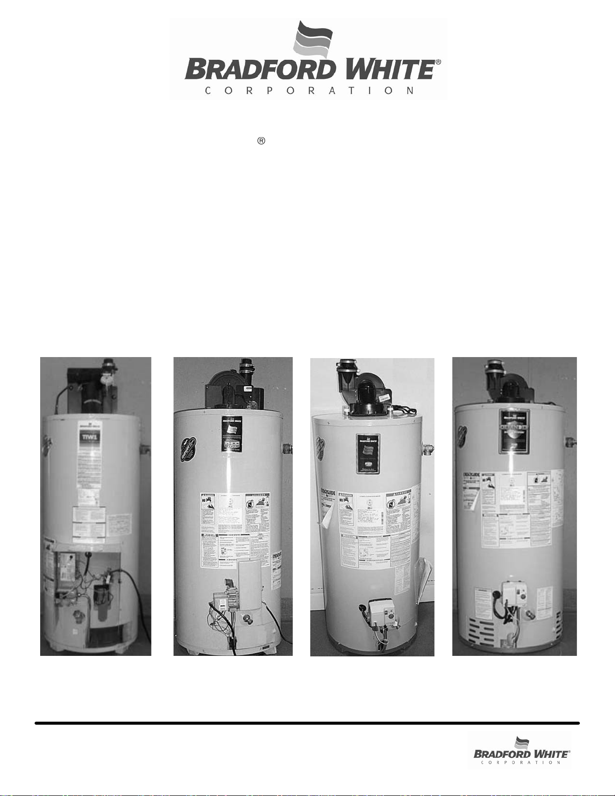
The Blowers on the Following Water
Heaters are Serv iced by This Kit:
MITW -10
Series
MITW -12 / -15
Series
M1TW Se r ie s
(Normal & High Altitude)
(For full model numbers, see page 2.)
Manual 47216A Save this manual for future reference
Page 2

Model Numbers Reference
Water Heater Model Numbers Serviced by This Kit
Water Heater
Model Numbers
MITW40L*LN10
Origin al Blower’s P/N
MITW40L*CX10
239-39785-00
Series
MITW -10
MITW50L*LN10
MITW50L*CX10
MITW40L*EN12
MITW40L*BN12
MITW40L*CX12
239-41605-00
MITW50L*EN12
MITW50L*BN12
MITW50L*CX12
MITW40L*EN15
MITW40L*BN15
MITW -12 / -15 SeriesM1TW Se ries
MITW40L*CX15
239-41605-00
MITW50L*EN15
MITW50L*BN15
Page 2
MITW50L*CX15
M1TW40S*BN
M1TW40S*CX
M1TW50S*BN
239-45584-00
243-45987-00 (Hi-Alt)
M1TW50S*CX
M1TW40S*FBN
M1TW40S*FCX
M1TW50S*FBN
M1TW50S*FCX
239-45584-00
243-45987-00 (Hi-Alt)
M1TW60T*FBN
M1TW60T*FCX
(*) Denotes Warranty Years (Typically “5”, “6”, or “10”)
Page 3
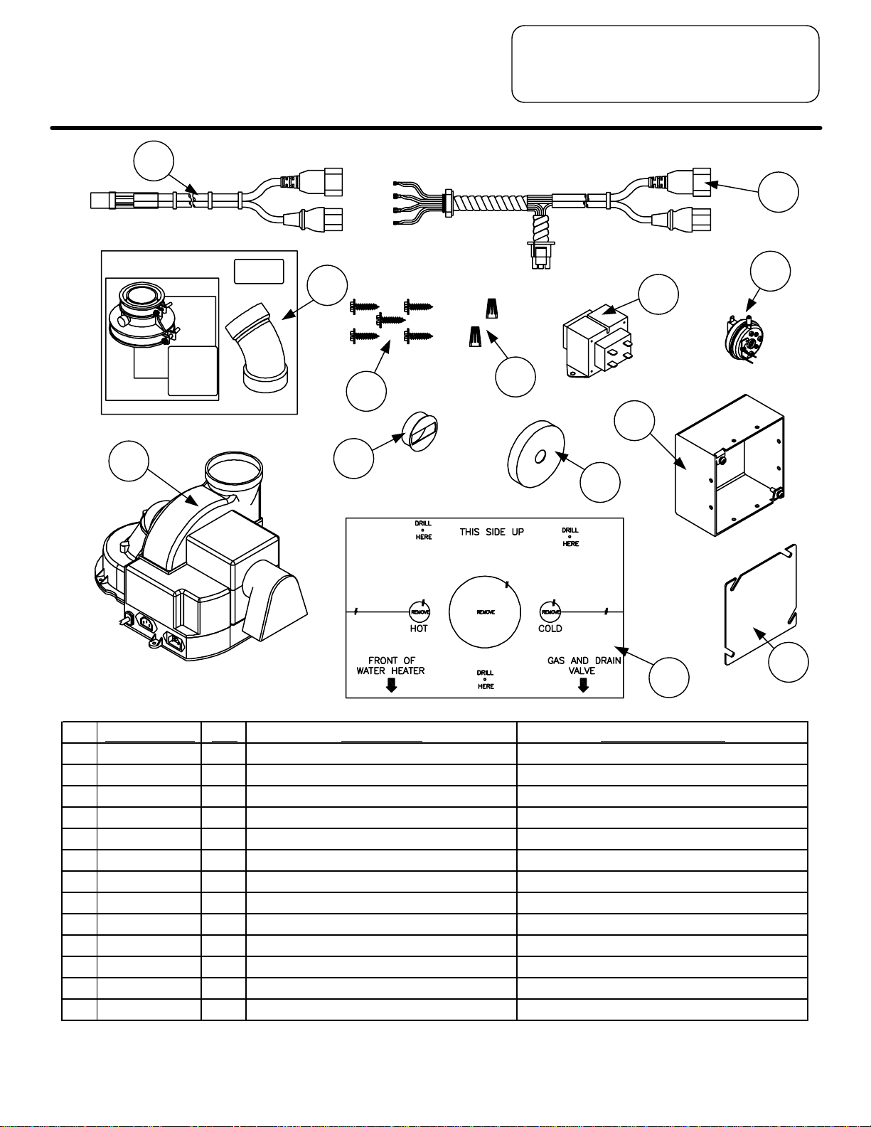
Kit Components
3
2
10
4
13
8
7
5
1
9
11
6
12
Part Number Qty De s cription Models Used On:
1 265-47195-00 1 Universa l Blowe r All
2 239-47194-00 1 Wire Harness MI TW- 12/15 Series MITW -12 / -15 Series
3 239-47193-00 1 Wire Harness MI TW- 10 S eries MITW -10 Series
4 239-46263-00 1 2" Exhaus t Adapter & Vent Terminal Kit All
5 239-47196-00 1 Trans former Junction Box MITW -12 / -15 Series
6 239-47199-00 1 Trans former Junction Box Cover MITW -12 / -15 Series
7 265-44072-01 1 Trans former (120V / 24V) MITW -12 / -15 Series
8 239-44113-00 5 Screws All
9 239-47190-00 1 Dilution Air O r ifice M1TW Serie s (normal & high altitude )
10 239-47192-01 1 P r es s ur e Sw itch ( - 0.70" wc) M1TW Serie s (high altitude only)
11 239-47191-00 1 Flue Re str ict or MIT W - 10 Se ries & MITW - 12 / -15 S e r ies
12 238-47197-00 1 Te mplate MIT W - 10 Se ries & MI T W -12 / -15 Se r ies
13 239-47281-00 2 Wire N ut s MIT W - 10 Se ries & MITW - 12 / -15 S e r ies
For full model numbers, see page 2 (Model Number Refer ence Pag e).
Page 3
Page 4

Tools Required
¼" Nut Driver
5/16" Nut Driver
Slotted Screwdriver
Philips Screwdriver
Hammer
1/8" Drill Bit
Drill
Channel Lock Pliers
Needle Nose Pliers
Tape (preferably scotch or masking)
PVC Primer / Cement
Wire Cutters
Wire Strippers
Wire Brush
Hacksaw
Page 4
Page 5

Bradford Whit e
TTW 1 Universal Service
Replacement Blower Kit
P/N 265-47200-00
Table of Contents
Page
Kit Components 3
Tools Required 4
MITW -1 0 Se r i es W at e r Heaters: 6
MITW40L*LN10, MITW40L*CX10, MITW50L*LN10,
MITW50L*CX10
MITW -12 / -15 Series Wate r Heaters: 12
MITW40L*EN12, MITW40L*BN12, MITW40L*CX12,
MITW50L*EN12, MITW50L*BN12, MITW50L*CX12,
MITW40L*EN15, MITW40L*BN15, MITW40L*CX15,
MITW50L*EN15, MITW50L*BN15, MITW50L*CX15
M1TW Series Water Heaters: 21
M1TW40S*BN, M1TW40S*CX, M1TW50S*BN,
M1TW50S*CX, M1TW40S*FB N, M1TW40S*FCX,
M1TW50S*FBN, M1TW50S*FC X, M1TW60T*FBN,
M1TW60T*FCX
Notes 27
(*) Denotes Warranty Years (Typically “5”, “ 6”, or “10”)
Notice: To determine what series water heater is being serviced, please refer to the
model numbers shown below each series title. Then, turn to the applicable
page for the correct water heater series.
Page 5
Page 6
TTW1 Universal Service
Replacement Blower
MITW -10 Series
Note: This set of instructions is for the following model numbers: MITW40L*LN10,
MITW40L*CX10, MITW50L*LN10, and MITW50L*CX10.
Note: The following parts are required to convert the model numbers shown above:
Template, Flue Restrictor, Screws, Wire Harness MITW-10 Series, Universal Blower,
Wire Nuts, and 2" Exhaust Adapter / Vent Terminal Kit. Please refer to the Kit
Components page (Page 3) for a picture of each item.
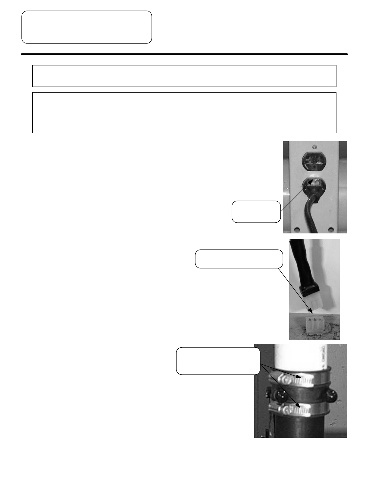
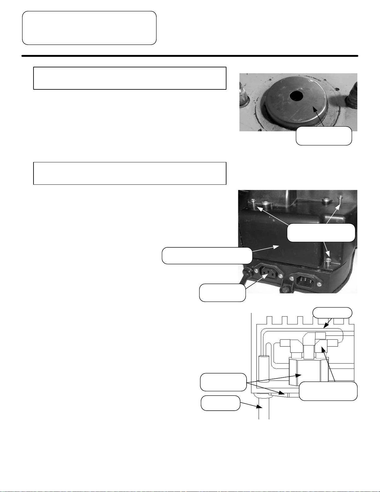
Step 1. Unplug water heater from wall outlet.
Unplug blower harness from
jacket head receptacle.
Step 2. Detach blower wire harness from receptacle
located in the jacket head.
Unscrew both clamps that
hold the adapter to the
blower and vent pipe.
Remove power
cord from outlet.
Step 3. Disconnect the vent pipe and adapter that are
connected to the outlet of the blower.
Page 6
Page 7
Step 4. Remove the screws, qty. (4), that secure
the blower to the jacket head.
Step 5. Remove blower from the top of the water
heater. Remove any loose debris and
tools from the top of the water heater,
including any portion of the blower gasket
that still exists.
TTW1 Universal Service
Replacement Blower
MITW -10 Series
Unscrew (4) screws that hold
blower to the jacket head.
Warning: Failure to locate the blower correctly will
result in improper water heater operation.
Step 6. Create the new mounting hole locations
for the new universal replacement blower.
Use template supplied with manual.
a.) On the template, P/N 238-47197-00,
the (3) circular sections for the water
connections and flue have already
been removed. Also, the dotted lines
from the side of the paper are
perforated for easy tearing.
Slip the template over the wat er conne c tions. It
is not necessary to remove the pipes connected
to the water heater’s inle t and out let.
b.) Place the template on top of the water
heater, being sure to have the arrows
point towards the front of the water
heater, which is the side where the
drain and gas valve are located. Tape
the template to the top of the water
heater to hold it in place.
The (3) circular sections
on template have been
pre-cut and removed.
Tear paper along dotted lines
where perforation exists, or cut
with scissors.
Place template on top of water
heater in correct orientation.
c.) At each of the (3) “Drill Here” locations
on the template, drill a 1/8” diameter
hole through the template and the
jacket head. Remove the template
from the top of the water heater.
Drill (3) locations on top of water heater,
where “Drill Here” is noted on the template.
Drill
Page 7
Page 8
TTW1 Universal Service
Replacement Blower
MITW -10 Series
Warning: Failure to install flue restrictor will result in
improper water heater operation.
Step 7. Install the flue restrictor, P/N
239-47191-00, firmly on the flue. It may
be necessary to lightly tap down the flue
restrictor. Be sure to tap it evenly and
straight down. Wire brush the top of the
water heater if rust or corrosion exists.
Warning: Do NOT remove Torx head screws from
universal blower.
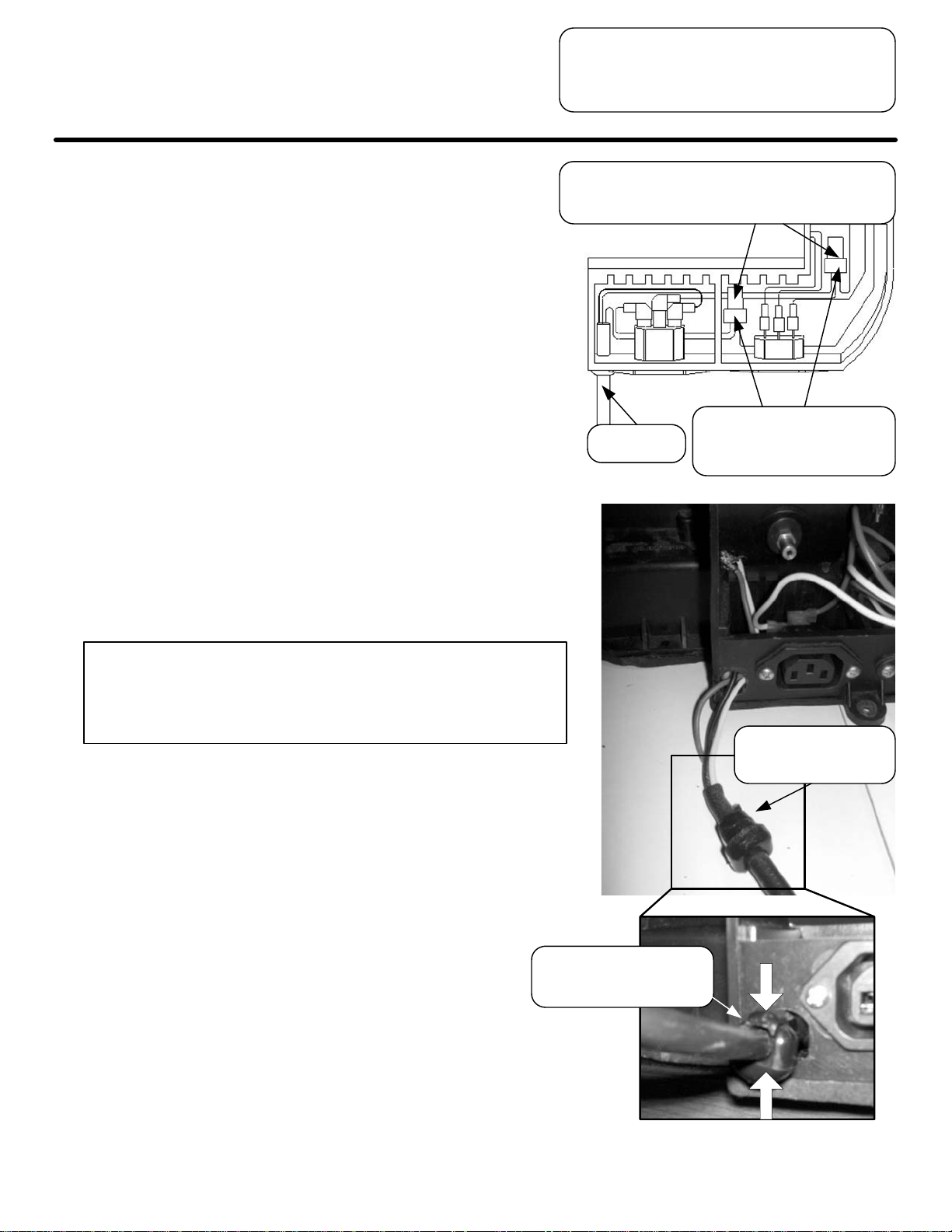
Step 8. Instructions to remove power cord from
new universal blower:
a.) Unscrew the (3) Philips head screws
on the blower access cover and
remove the cover. Keep the cover and
screws for future use.
Blower access cover
(covers access compartmen t)
Place flue
restrictor on flue.
Loosen all (3) screws
holding cover on.
Power inlet
connector
b.) Inside the access compartment, follow
the black wire from the power cord until
you reach the flag terminal attached to
the end of the wire. Disconnect black
wire from the back of the power inlet
connector.
Power inlet
connector
Power cord
Black wire
Remove black
wire’s flag terminal
Page 8
Page 9
Step 8.
c.) Just below the crimp connector, cut the
(3) white (neutral) wires. Remove the
white power cord lead from the bundle.
Then, strip the ends of the (2)
remaining white wires and connect
them using a wire nut, included with
the kit, P/N 239-47281-00, and tuck the
wires back into the lower portion of the
access compartment.
d.) Just below the crimp connector, cut the
(3) green (ground) wires. Remove the
green power cord lead from the
bundle. Then, strip the ends of the (2)
remaining green wires and connect
them using a wire nut, included with
the kit, P/N 239-47281-00, and tuck the
wires back into the lower portion of the
access compartment.
TTW1 Universal Service
Replacement Blower
MITW -10 Series
Cut just below these crimp co nnectors. Then,
remove (1) white and (1) green wire from
bundles. Trace wires back to power cord.
Connect (2) white wir es
Power cord
and (2) green wires, each
with their own wire nut.
Warning: Make sure that each wire nut is securely
tightened and that all wires are making
good connection or improper water heater
operation will occur.
e.) Remove the power cord from the
blower housing and discard.
f.) Verify that all electrical connections
have been modified, as previously
indicated. Also, verify that the
pressure switch tubing is connected to
the pressure tap on the blower
and to the switch itself. Ensure that
the tubing is not kinked.
Squeeze bushing to
remove power cord
from blower.
Push in both sides of
the bushing with pliers
to remove.
Page 9
Page 10

TTW1 Universal Service
Replacement Blower
MITW -10 Series
Step 9.
a.) Ensure that the pressure switch, P/N
239-47192-02, is mounted in the
vertical position, as shown. This
pressure switch comes standard in the
blower from the factory. Its vacuum
setting should read -0.80" wc.
b.) Place the access compartment cover
back on the blower and secure with (3)
screws from Step 8a. Start the lower
screw first, and when doing so, make
sure that the hole in the pressure
switch’s bracket matches up to the
hole in the blower housing.
Warning: Do NOT over tighten (3) screws attaching
the blower to the water heater.
Step 10. Now that the universal blower is properly
modified for a -10 series water heater, the
blower can be properly positioned and
secured on top of the water heater. To
place the blower on the water heater, feed
the blower from around the backside of
the water connections. Secure the
universa l blower using (3 ) screws, P/N
239-44113-00, provided with the kit, into
the pilot holes created in Step 6. Tighten
them using a ¼” nut driver.
Step 11. Find the correct universal blower wire
harness provided with the kit, P/N
239-47193-00. Connect the wire harness
to the receptacle in the jacket head and
into the receptacles in the blower housing.
Verify electrical
and tubing
connections.
Secure (3)
screws.
Secure (3)
blower
screws.
Mount in vertical
position using
bracket.
cover
Page 10
Plug both the blower
cord sets into the blower
receptacles.
Insert other end of wire
harness into receptacle on
jacket head.
Page 11

Step 12. Find the rubber vent adapter kit, P/N
239-46263-00, provided with the
blower kit. Install the 2” vent adapter
on theexhaust side of the universal
blower. Discard the vent terminal
included with the vent adapter kit.
Note: In order to prevent condensate from draining
back into the blower (vertical or horizontal runs),
an optional condensate kit is available as a
service part (Condensate kit, P/N 239-45875-00).
Step 13. If it has not already been done,
remove the old vent adapter from the
existing vent pipe.
TTW1 Universal Service
Replacement Blower
MITW -10 Series
Be sure that vent pipe is
properly seated in the top
side of vent adapter.
Rubber vent
adapter
Step 14. If necessary, re-route the vent pipe
such that it can be properly seated in
the top portion of the vent adapter.
Step 15. Be sure that both clamps on the vent
adapter are firmly tightened, securing
the blower, vent adapter, and vent pipe
together.
Step 16. Double-check all vent connections.
Step 17. Restore electrical power to the water
heater.
Plug power cord
back into outlet.
Adequately tight en both
clamps on the vent adapter.
Warning: Check all safety devices to make sure they
are working properly. Improper water heater
operation could occur if these devices are not
functioning properly.
Page 11
Page 12

TTW1 Universal Service
Replacement Blower
MITW -12 / -15 Series
Note: This set of instructions is for the following model numbers: MITW40L*EN12,
MITW40L*BN12, MITW40L*CX12, MITW50L*EN12, MITW50L*BN12,MITW50L*CX12,
MITW40L*EN15, MITW40L*BN15, MITW40L*CX15, MITW50L*EN15,
MITW50L*BN15, and MITW50L*CX15.
Note: The following parts are required to convert the model numbers
shown above: Template, Flue Restrictor, Screws, Wire Harness
MITW-12/15 Series, Universal Blower, Transformer, Junction
Box & its Cover, Wire Nuts, and 2" Exhaust Adapter / Vent
Terminal Kit. Please refer to the Kit Components page (Page 3)
for a picture of each item.
Step 1. On the water heater’s gas control, turn the
power switch to the “Off” position.
Tur n s w itch on gas
valve to “Off” position.
Step 2. Unplug the water heater from wall outlet.
Remove power
Unscrew both clamps that
hold the adapter to the
blower and vent pipe.
cord from
outlet.
Step 3. Disconnect the vent pipe and adapter that
are connected to the outlet of the blower.
Page 12
Page 13

Step 4. Remove the screws, qty. (3), that secure
the blower to the jacket head.
Unscrew (3) screws that hold
blower to the jacket head.
Blower junction box
TTW1 Universal Service
Replacement Blower
MITW -12 / -15 Series
Step 5. Disconnect blower wire harness from
receptacle, located in the jacket head
under the blower junction box. The white
connector must be pinched to remove.
Step 6. Remove the blower from the top of the
water heater. Remove any loose debris
and tools from the top of the water heater.
Warning: Failure to locate the blower correctly will
result in improper water heater operation.
Step 7. Create the new mounting hole locations
for the new universal replacement blower.
Use template supplied with manual.
a.) On the template, P/N 238-47197-00,
the (3) circular sections for the water
connections and flue have already
been removed. Also, the dotted lines
from the side of the paper are
perforated for easy tearing.
Unplug blower harness from
jacket head receptacle by
pinching the connector.
The (3) circular sections
on template have been
pre-cut and removed.
Tear paper along dotted lines
where perforation exists, or cut
with scissors.
Page 13
Page 14

TTW1 Universal Service
Replacement Blower
MITW -12 / -15 Series
Slip the template over the wat er conne c tions. It
is not necessary to remove the pipes connected
to the water heater’s inle t and out let.
Step 7.
b.) Place the template on top of the water
heater, being sure to have the arrows
point towards the front of the water
heater, which is the side where the
drain and gas valve are located. Tape
the template to the top of the water
heater to hold it in place.
c.) At each of the (3) “Drill Here” locations
on the template, drill a 1/8” diameter
hole through the template and the
jacket head. Remove the template
from the top of the water heater.
Place template on top of water
heater in correct orientation.
Drill
Drill (3) locations on top of water heater,
where “Drill Here” is noted on the template.
Warning: Failure to install flue restrictor will result in
improper water heater operation.
Step 8. Install the flue restrictor, P/N
239-47191-00, firmly on the flue. It may
be necessary to lightly tap down the flue
restrictor. Be sure to tap it evenly and
straight down. Wire brush the top of the
water heater if rust or corrosion exists.
Warning: Do NOT remove Torx head screws from
universal blower.
Step 9. Instructions to remove power cord from
new universal blower:
a.) Unscrew the (3) Philips head screws
on the blower access cover and
remove the cover. Keep the cover and
screws for future use.
Place flue
restricto r on flue.
Loosen all (3) screws
holding cover on.
Page 14
Blower access cover
(covers access compartmen t)
Power inlet
connector
Page 15

Step 9.
b.) Inside the access compartment, follow
the black wire from the power cord until
you reach the flag terminal attached to
the end of the wire. Disconnect black
wire from the back of the power inlet
connector.
Power inlet
connector
Power cord
TTW1 Universal Service
Replacement Blower
MITW -12 / -15 Series
Black wire
Remove black
wire’s flag termina l
c.) Just below the crimp connector, cut
the (3) white (neutral) wires. Remove
the white power cord lead from the
bundle. Then, strip the ends of the (2)
remaining white wires and connect
them using a wire nut, included with
the kit, P/N 239-47281-00, and tuck the
wires back into the lower portion of the
access compartment.
d.) Just below the crimp connector, cut the
(3) green (ground) wires. Remove the
green power cord lead from the
bundle. Then, strip the ends of the (2)
remaining green wires and connect
them using a wire nut, included with
the kit, P/N 239-47281-00, and tuck the
wires back into the lower portion of the
access compartment.
Warning: Make sure that each wire nut is securely
tightened and that all wires are making
good connection or improper water heater
operation will occur.
Cut just below these crim p con nec tors.
Then, remove (1) white and (1) gr een
wire from bundles. Trace wires back
to power cord.
Connect (2) white wir es
Power cord
and (2) green wires, each
with their own wire nut.
e.) Remove the power cord from the
blower housing and discard.
Push in both sides of
the bushing with plier s
to remove.
Squeeze bushing to
remove power cord
from blower.
Page 15
Page 16

TTW1 Universal Service
Replacement Blower
MITW -12 / -15 Series
Step 9.
f.) Verify that all electrical connections
have been modified, as previously
indicated. Also, verify that the
pressure switch tubing is connected to
the pressure tap on the blower
and to the switch itself. Ensure that
the tubing is not kinked.
Step 10.
a.) Ensure that the pressure switch, P/N
239-47192-02, is mounted in the
vertical position, as shown. This
pressure switch comes standard in the
blower from the factory. Its vacuum
setting should read -0.80" wc.
Verify electrical
and tubing
connections.
Mount in vertical
position using
bracket.
b.) Place the access compartment cover
back on the blower and secure with (3)
screws from Step 9a. Start the lower
screw first, and when doing so, make
sure that the hole in the pressure
switch’s bracket matches up to the
hole in the blower housing.
Warning: Do NOT over tighten (3) screws attaching
the blower to the water heater.
Step 11. Now that the universal blower is properly
modified for a -12/-15 series water heater,
the blower can be properly positioned and
secured on top of the water heater. To
place the blower on the water heater, feed
the blower from around the backside of
the water connections. Secure the
universa l blower using (3 ) screws, P/N
239-44113-00, provided with the kit, into
the pilot holes created in Step 7. Tighten
them using a ¼” nut driver.
Secure (3)
cover
screws.
Secure (3)
blower
screws.
Page 16
Page 17

TTW1 Universal Service
Replacement Blower
MITW -12 / -15 Series
Step 12.
a.) Position the junction box, P/N
239-47196-00, on top of the water
heater, in front of the blower, and on
the side nearest the T&P valve.
b.) Place the transformer, P/N
265-44072-01, inside the junction box
such that there is sufficient room
between its (4) posts and the sidewalls
of the junction box. Determine the side
to remove a knock-out. Remove the
transformer from the junction box.
Plac e junction bo x
on top of water
heater and
transformer in box.
Blower
harness
receptacles
Leave room in corner
closest to blower harness
receptacles to attach
terminals to transformer.
Remove ¾"
knockout.
c.) On a side opposite the transformer's
posts, remove (1) knock-out ¾" in size.
Then, place the junction box back on
the water heater and the transformer
back into the box.
d.) Mark the location of the mounting
holes of the transformer onto the
junction box.
e.) Remove the transformer from the
junction box.
f.) Drill (2) 1/8” diameter holes in the
locations that were marked in Step
12d. Be sure that the pilot holes are
through the junction box and jacket
head.
Junction box
Mark the location of
transformer in box.
Transformer
Page 17
Page 18

TTW1 Universal Service
Replacement Blower
MITW -12 / -15 Series
Step 13. Locate new blower harness, P/N
239-47194-00, provided with the kit.
Route loose wire ends (yellow, blue,
white, and green) through knock-out
opening from Step 12c.
Step 14. Fasten conduit connector to the junction
box.
Step 15. Connect the wire terminals to their
corresponding locations on the
transformer:
a.) (2) Blue wires and wire terminal to the
120V-Hot post
b.) (2) White wires and wire terminal to the
120V-Common post
c.) (2) Yellow wires and wire terminal to
the 24V-Hot post
d.) (2) Green wires and wire terminal to
the 24V-Common post
Route wires
through hole in
junction box.
Fasten connector
to junc ti on box.
Warning: Do NOT over tighten (2) screws attaching
the transformer and junction box to the
water heater.
Step 16. Place the transformer all the way back
into the junction box and fasten both to
the water heater using (2) screws, P/N
239-44113-00, provided with the kit.
Fasten transformer and
junction box to jack et head
(Second screw not shown).
Page 18
Connect wire termi nals from
harness to proper posts .
Page 19

Step 17. Secure the junction box cover, P/N
239-47199-00, to the junction box.
Tighten (2) screws on junction
box to secure cover.
Step 18. With the blower and transformer assembly
fastened to the water heater, the
remaining ends of the blower wire harness
can now be attached with the cord sets to
the blower and then the white connector
to the receptacle in the jacket head.
TTW1 Universal Service
Replacement Blower
MITW -12 / -15 Series
Plug cord sets into
receptacles in blower.
Plug white connector into
receptacle in jacket head.
Step 19. Find the rubber vent adapter kit, P/N
239-46263-00, provided with the blower
kit. Install the 2” vent adapter on the
exhaust side of the universal blower.
Discard the vent terminal included with
the vent adapter kit.
Note: In order to prevent condensate from draining
back into the blower (vertical or horizontal runs),
an optional condensate kit is available as a
service part (Condensate kit, P/N 239-45875-00).
Be sure that vent pipe is
properly seated in t he top
side of vent adapter.
Rubber vent adapter
Adequately tight en both
clamps on the vent adapter.
Page 19
Page 20

TTW1 Universal Service
Replacement Blower
MITW -12 / -15 Series
Step 20. If it has not already been done, remove
the old vent adapter from the existing vent
pipe.
Step 21. If necessary, re-route the vent pipe such
that it can be properly seated in the top
portion of the vent adapter.
Step 22. Be sure that both clamps on the vent
adapter are firmly tightened, securing the
blower, vent adapter, and vent pipe
together.
Step 23. Double-check all vent connections.
Step 24. Restore electrical power to the water
heater.
Step 25. On the water heater’s gas control, turn the
power switch to the “On” position.
Turn switch on gas
valve to “On” position.
Plug power cord
back into outlet.
Warning: Check all safety devices to make sure they
are working properly. Improper water heater
operation could occur if these devices are not
functioning properly.
Page 20
Page 21

TTW1 Universal Service
Replacement Blower
Note: This set of instructions is for the following model numbers:
M1TW40S*BN, M1TW40S*CX, M1TW50S*BN,
M1TW50S*CX, M1TW40S*FBN, M1TW40S*FCX,
M1TW50S*FBN, M1TW50S*FCX, M1TW60T*FBN, and
M1TW60T*FCX.
Note: The following parts are required to convert the model numbers
shown above: Screws, Universal Blower, Dilution Air Orifice,
Pressure Switch (-0.70" wc, for high altitude only), and 2"
Exhaust Adapter / Vent Terminal Kit. Please refer to the Kit
Components page (Page 3) for a picture of each item.
Step 1. On the water heater’s gas control, turn the
power switch to the “Off” position.
M1TW Se ri e s
Turn switch on gas valve
to “Off” position.
Step 2. Unplug water heater from wall outlet.
Unplug blower harness
cord sets from blower
housing receptacles.
Remove power
cord from outlet.
Step 3. Disconnect blower cord sets from
receptacles located in the blower housing.
Page 21
Page 22

TTW1 Universal Service
Replacement Blower
M1TW Series
Step 4. Disconnect the vent pipe and adapter that
are connected to the outlet of the blower.
Unscrew both clamps that
hold the adapter to the
blower and vent pipe.
Unscrew (3) screws that hold
blower to the jacket head.
Step 5. Remove the screws, qty. (3), that secure
the blower to the jacket head.
Step 6. Remove blower from the top of the water
heater. Remove any loose debris and
tools from the top of the water heater.
Warning: For normal altitude applications (2000 ft. & below), proceed to Step 8.
Otherwise, for high altitude applications (2001 ft. & above), continue with
Step 7.
Step 7. Instructions to replace universal blower
pressure switch:
Warning: Only replace the pressure switch if the
water heater is being used in high altitude
Blower access cover
(covers access compartment)
application. Failure to replace universal
blower pressure switch will result in
improper water heater operation.
a.) Unscrew the (3) Philips head screws
on the blower access cover and
remove the cover. Keep the cover and
Loosen all (3) screws
holding cover on.
screws for future use.
Warning: Do NOT remove Torx head screws from
universal blower.
Page 22
Page 23

Step 7.
TTW1 Universal Service
Replacement Blower
M1TW Se ri e s
Disconnect (2) flag
terminals and tubing
from pressure switch
to remove.
b.) Replace the current pressure switch
ONLY IF the model is for high altitude
(2001 ft. & above).
Warning: Failure to replace universal blower pressure
switch for high altitude will result in improper
water heater operation.
i. For high altitude applications, the
factory installed pressure switch
must be replaced. The correct
pressure switch is P/N
239-47192-01 with a setting of
-0.70" wc.
c.) When installing the high altitude
pressure switch, be sure to reconnect
the pressure switch tubing to both the
pressure tap and the switch itself.
Also, reconnect the wires for the
pressure switch circuit to the new
pressure switch. Ensure that
the tubing is not kinked.
Choose corresponding pr es sure switch
from kit. Verify correct P/N and setting
on label to match this model’s
requirements, as shown in Step 7b.
Be sure to reconnect
tubing and (2) flag
terminals.
Step 8. a.) Ensure that once in place, the pressure
switch should be mounted such that its
diaphragm is in the vertical position.
Verify electrical
and tubing
connections.
Mount in vertical
position using
bracket.
Page 23
Page 24

TTW1 Universal Service
Replacement Blower
M1TW Series
Step 8.
b.) Place the access compartment cover
back on the blower and secure it with
its (3) screws from Step 7a. Start the
lower screw first, and when doing so,
make sure that the hole in the pressure
switch’s bracket matches up to the
hole in the blower housing.
Secure (3)
cover screws.
Step 9. a.) Remove the intake boot from the rear
of the blower.
b.) Place dilution air orifice, P/N
239-47190-00, in the hole, located in
the rear of the blower, being sure to
adjust the slot in the orifice such that it
is horizontal, as shown.
Insert dilution air orifice into area
concealed by boot. Orient slot in
orifice to horizontal position.
Remove air
intake boot.
Page 24
Page 25

Step 9.
TTW1 Universal Service
Replacement Blower
M1TW Series
c.) Replace the intake boot back onto the
blower. If it is necessary, the cable, or
zip, tie can be removed from the boot
to allow for easier assembly.
Replace boot on
rear of blower.
Remove cable tie if boot
will not go onto rear of
blower easily.
Step 10. Now that the universal blower is properly
modified for a M1TW series water heater,
the blower can be properly positioned and
secured on top of the water heater. To
place the blower on the water heater, feed
the blower from around the backside of
the water connections. Secure the
universa l blower using (3 ) screws, P/N
239-44113-00, provided with the kit, into
the pre-existing holes used to fasten the
original blower. Tighten them using a ¼”
nut driver.
Plug blower harness cord se ts
into blower housing receptacles.
Boot back
in place.
Secure (3) blower screws.
Step 11. With the blower securely fastened to the
water heater, the blower wire harness
cord sets can now be re-connected to the
blower housing.
Page 25
Page 26

TTW1 Universal Service
Replacement Blower
M1TW Series
Step 12. Find the rubber vent adapter kit, P/N
239-46263-00, provided with the blower
kit. Install the 2” vent adapter on the
exhaust side of the universal blower.
Discard the vent terminal included with
the vent adapter kit.
Be sure that vent pipe is properly
seated in the top side of vent adapter.
Note: In order to prevent condensate from draining
back into the blower (vertical or horizontal runs),
an optional condensate kit is available as a
service part (Condensate kit, P/N 239-45875-00).
Step 13. If the new adapter is used, remove the old
vent adapter from the existing vent pipe.
Step 14. Be sure that both clamps on the vent
adapter are firmly tightened, securing the
blower, vent adapter, and vent pipe
together.
Step 15. Double-check all vent connections.
Step 16. Restore electrical power to the water
heater.
Turn switch on gas
valve to “On” position.
Step 17. On the water heater's gas control, turn the
power switch to the “On” position.
Rubber vent adapter
Adequately tighten both
clamps on the vent adapter .
Plug power cord
back into outlet.
Warning: Check all safety devices to make sure they
are working properly. Improper water heater
operation could occur if these devices are not
functioning properly.
Page 26
Page 27

NOTES
Notes
Page 27
 Loading...