

Bradford White ES-3000-2-S-10, ES-3500-1-S-10, ES-3000-1-S-10, ES-3000-5-S-10, ES-3500-4-S-10 Installation Manual And Owner's Manual
...Page 1
ELECTRIC INSTANTANEOUS TANKLESS WATER HEATER
INSTALLATION GUIDE AND OWNERS MANUAL
ELEMENT CARTRIDGE
HEATER MODEL/ORDER REF. CARTRIDGE REF #
RELAY
PART#EX250B-
EX254B
FLOW RESTRICTOR
AERATOR
PART # EX0061-0.5-AER
CONTROL BOARD
EX0183DL-30A for
120V, 277V,
240V, 208V
REPLACEMENT PARTS FOR “Single Point” MODELS
CALL TECHNICAL SERVICE
@ 1-800-334-3393
COMPRESSION
SLEEVE 3/8”
PART # EX68C
COMPRESSION
NUT 3/8”
PART #EX68B
WARNING
BEFORE ATTEMPTING INSTALLATION OF THIS UNIT OR MAKING ANY
ADJUSTMENTS TO T HE UNIT, BE SURE CIRCUIT BREAKER IS OFF
TO PREVENT DANGER OF SERIOUS ELECTRIC SHOCK.
FAILURE TO GROUND THE SYSTEM MAY RESULT IN SERIOUS INJURY OR DEATH
INSTALLER/ CONSUMER RESPONSIBILITIES
READ THIS MANUAL CAREFULLY BEFORE ATTEMPTING TO INSTALL OR
OPERATE THIS WATER HEATING UNIT. IF THE SAFETY RULES ARE NOT
FOLLOWED, THE UNIT WILL NOT OPERATE PROPERLY AND COULD CAUSE
DEATH, SERIOUS BODILY INJURY AND/OR PROPERTY DAMAGE. WARRANTY
OF THIS UNIT WILL DEPEND ON PROPER INSTALLATION AND OPERATION.
THE WARRANTY WILL BE VOID IF THE DESIGN HAS BEEN ALTERED IN ANY WAY
WHATSOEVER. THE MANUFACTURER OF THIS UNIT WILL NOT BE LIABLE
FOR ANY DAMAGES BECAUSE OF FAILURE TO COMPLY WITH THE INSTALLATION
AND OPERATING INSTRUCTIONS OUTLINED ON THE FOLLOWING PAGES.
THE INSTALLATION MUST CONFORM WITH THE INSTRUCTIONS IN THIS
MANUAL AND THE LOCAL CODES, OR IN THE ABSENCE OF LOCAL CODES,
WITH THE LATEST EDITION OF THE NATIONAL ELECTRICAL CODE. THE
NATINOAL ELECTRICAL CODE IS AVAILABLE FROM WRITING
UNDERWRITERS LABORATORIES, 333 PFINGSTEN RD.,
NORTHBROOK, IL. 60062
IF ASSTANCE IS REQUIRED OR ANY QUESTIONS RELATING
TO THE INSTALLATION OR PERFORMANCE OF THIS UNIT ARISE,
PLEASE CONTACT
TECHNICAL SERVICE TOLL FREE:1-800-334-3393.
HAVE THE INFORMATION LISTED BELOW BEFORE CALLING:
MODEL NO.___________SERIAL NO.___________INSTALLATION DATE_____
“SINGLE POINT”
MODELS COVERED:
ES-2400-1-S-10 ES-3000-1-S-10
ES-3000-2-S-10 ES-3000-5-S-10
ES-3500-1-S-10 ES-3500-4-S-10
ES-4100-2-S-10 ES-4100-5-S-10
ES-5500-4-S-10
ES-2400-1-S-10 120V EX610SP
ES-3000-1--S-10 120V EX480SP
ES-3500-1-S-10 120V EX410SP
ES-3000-2-S-10 120V EX1440SP
ES-4100-2-S-10 208V EX1050SP
ES-3500-5-S-10 240V EX1650SP
ES-4100-5-S-10 277V EX1870SP
ES-3000-5-S-10 277V EX2500SP
ES-5500-4-S-10 240V EX1050SP
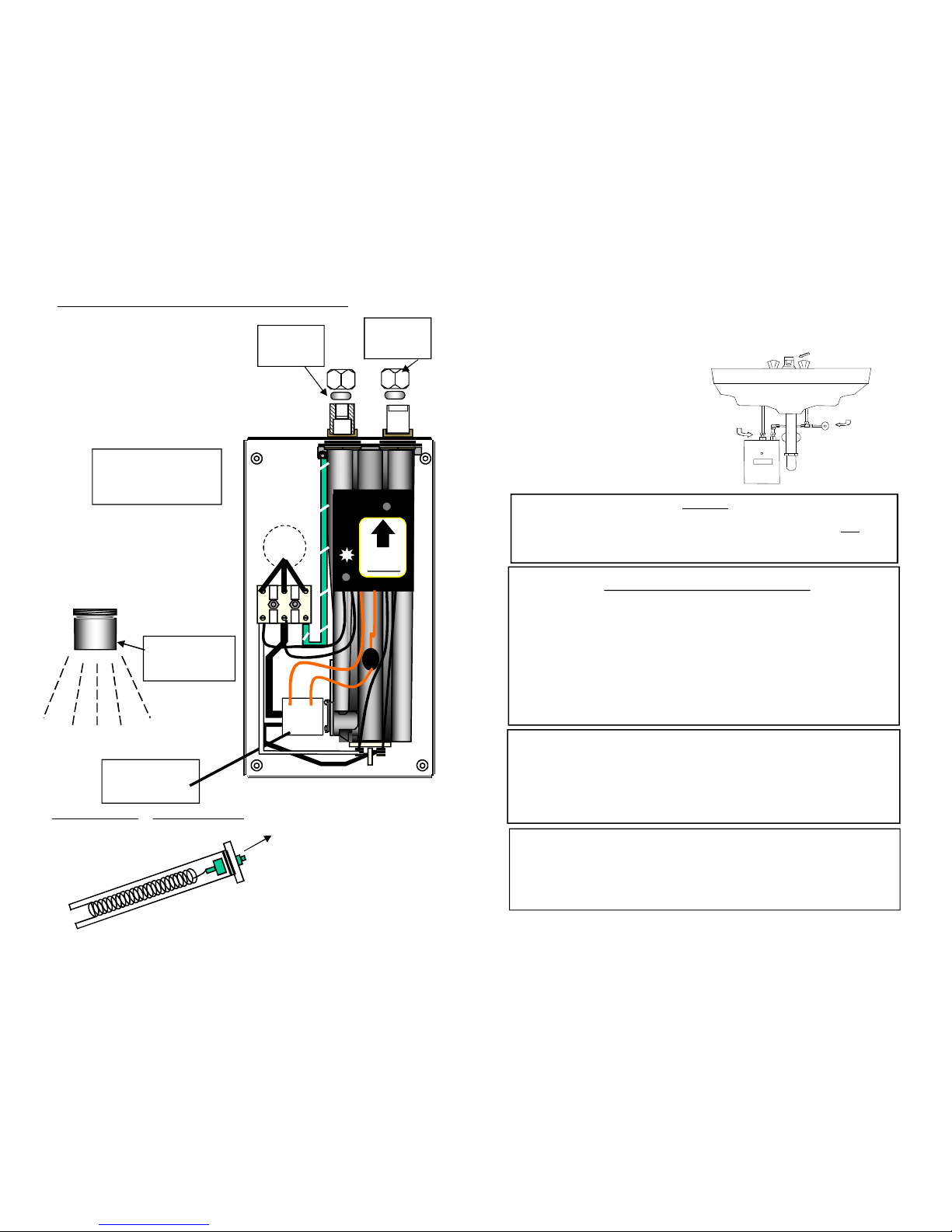
INSTALL
THIS WAY UP
ONLY !
UP
relay
Page 2
PLUMBING CONNECTIONS
1) The unit is supplied with 3/8’’ compression fittings. USE THESE: DO NOT
USE THREADED PIPE FITTINGS. DO NOT USE PIPE DOPE OR TEFLON
TAPE ON THIS INSTALLATION. Ensure the inlet filter supplied with this unit
is in place.
2) Ensure that the pipes are correctly aligned with the inlet and
outlet bosses to avoid excessive stress on the heater body molding of the
unit.
NOTE: Run water through the supply pipe to remove all debris from the
pipe before connecting to the unit. Failure to do so could damage the flow
switch.
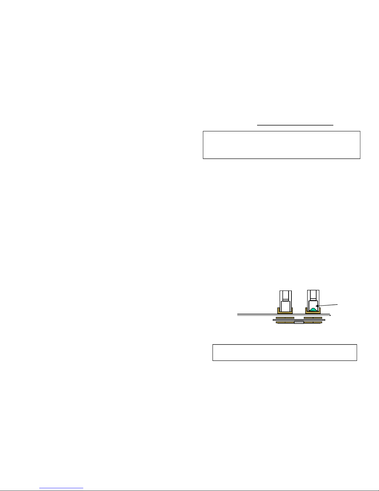
3) Install isolating valves (shut-off type),or equivalent on both inlet and outlet
pipes. This allows the unit to be isolated for maintenance purposes. (Fig. 2)
4) When all plumbing is complete, inspect the system for water leaks
at all plumbing connections. If a water leak is present take corrective action.
If a water leak is at the compression fitting, slowly tighten compression nut
until the water leaks ceases.
Fully open both inlet and outlet shut-off valves.
Run all hot water outlets fed by this heater one at a time until the water flow
is continuous and free from “gulping” and all visible air pockets.
NOTE:
ALL PLUMBING AND MOUNTING MUST BE COMPLETED
BEFORE PROCEEDING WITH THE
ELECTRICAL HOOK-UP.
TEST THE INSTALLATION FOR LEAKS BEFORE
CONNECTING THE ELECTRICAL SUPPLY.
.
Inlet
filter
Page 3

GENERAL
This “Single Point” water heating unit is specifically designed to be installed
“under sink” feeding a SINGLE faucet. This unit is designed to take in cold water
ONLY and heat it to temperatures suitable for hand washing. To obtain optimum
performance and energy savings, the unit should be located as near as possible
to the point of use. This unit incorporates a constant flow device and should only
be used with the faucet aerator supplied. The unit is supplied with compression
rings and nuts suitable for direct coupling to 3/8” copper or plastic piping. Do not
use additional screwed fittings or pipe dope. The use of such materials will void
the warranty. DO NOT SOLDER PIPES WHILE THE UNIT IS INSTALLED
(serious damage to the electronic flow switch will result).
INSTALLING THE UNIT
1) The unit must be mounted underneath a sink in a VERTICAL position with
the inlet and the outlet at the TOP. Mounting in anyway other than this
WILL cause element burn out and possibly damage the unit further.
Do not install this unit above the faucet as the siphoning effect will drain
the heater which can cause element burn out and damage the unit.
2) The cold water inlet is on the right hand side and the hot water outlet is
on the left hand side. Under NO circumstances can these be reversed.
3) Leave a minimum of 8” below the unit for easy replacement of the
element.
4) This unit should be fixed to the wall using the four mounting holes at
each corner of the backplate.
THIS HEATER M UST HAVE ITS OWN INDEPENDENT CIRCUIT, USING A
CORRECTLY RATED CIRCUIT BREAKER AND WIRES SUITABLE FOR AT
LEAST 75 OC OPERATION.
WARNING
UNIT MUST BE PROPERLY GROUNDED TO THE “GND” LOCATION
ON THE TERMINAL BLOCK. FAILURE TO GROUND THE SYSTEM MAY
RESULT IN SERIOUS INJURY OR DEATH.
Page 4

WARNING
BEFORE BEGINNING ANY WORK ON THE ELECT RICAL INSTALLATION BE SURE
THAT THE CIRCUIT BREAKER IS IN THE “OFF” POSITION TO AVOID ANY
DANGER OF ELECTRICAL SHOCK.
MODEL
VOLTS*
OUTPUT
CURRENT
TEMPERATURE RISE
0
F
kW
AMPS
0.5 gpm
0.6 gpm
0.7 gpm
ES-2400-1-S-10
120
2.42033--
ES-3000-1-S-10
120
3.025413429
ES-3500-1-S-10
120
3.5
29.2484034ES-3000-2-S-10
208
3.0
14.4413429ES-4100-2-S-10
208
4.1
19.7564740ES-3000-5-S-10
277
3.0
10.8413429ES-4100-5-S-10
277
4.1
14.8564740ES-3500-4-S-10
240
3.5
14.6484034ES-5500-4-S-10
240
5.522756354
RATINGS OF ‘’SINGLE POINT ” MODELS
* Units must be installed at rated voltage ONLY
THIS HEATER M UST BE INSTALLED ONLY IN A VERTICAL POSITION
WITH THE INLET AND OUTLET AT THE TOP
ELECTRICAL CONNECTIONS
This water heating must have its own independent circuit using
insulated, UL listed, 3 wire cable of the appropriate size suitable
for use up to 75°C protected by the correctly rated circuit breaker.
WARNING
Unit must be properly grounded to the “GND” location on the terminal block.
Failure to ground the system may result in serious injury or loss of life
Wire entry into the unit should be made through the lower right hand corner of the
backplate via one of the two “knockout” holes provided.
The “mains” wires should be connected to the slots in the terminal block marked
L1 and L2 (N). The ground lead must be connected to the slot marked
Failure to ground the system may result in death or serious injury.
WARNING
This water heater must not be switched “on” if there is a possibility that
the water in the heater is frozen
TO APPROPRIATE
SIZE BREAKER
WIRE ENTRY
EITHER THROUGH
REAR OR
BOTTOM
KNOCK-OUTS
MOUNTING HOLES
4 1/4 inches
8 inches
APPROPRIATE
GAUGE COPPER
WIRE (2 conductors
1 ground)
INSTALL
THIS WAY UP
ONLY !
UP
relay
ECO – AUTO
RESETTING HIGH
TEMPERATURE CUTOUT
 Loading...