

Bradford White EFT-6500-4-S-10, EFT-5500-4-S-10, EFT-8300-2-S-10, EFT-7500-4-S-10, EFT-9500-4-S-10 Installation Manual And Owner's Manual
...
ELECTRIC INSTANTANEOUS WATER
HEATER
INSTALLATION GUIDE AND OWNERS MANUAL
“THERMOSTATIC”
MODELS COVERED:
EFT-5500-4-S-10 240V
EFT-6500-4-S-10 240V
EFT-7500-4-S-10 240V
EFT-9500-4-S-10 240V
EFT-8300-2-S-10 208V
EFT-6000-5-S-10 277V
EFT-8000-5-S-10 277V
EFT-9000-5-S-10 277V
EFT-10000-5-S-10 277V
READ THIS MANUAL CAREFULLY BEFORE ATTEMPTING TO INSTALL OR OPERATE
THIS WATER HEATING UNIT. IF YOU DO NOT FOLLOW THE SAFETY RULES, THE
UNIT WILL NOT OPERATE PROPERLY AND COULD CAUSE DEATH, SERIOUS
BODILY INJURY AND OR PROPERTY DAMAGE.
READ ALSO THE ENCLOSED WARRANTY CARD. WARRANTY OF THIS WATER
HEATING UNIT WILL DEPEND ON PROPER INSTALLATION AND OPERATION. THE
WARRANTY SHALL BE VOID IF THE DESIGN HAS BEEN ALTERED IN ANY WAY
WHATSOEVER. THE MANUFACTURER OF THIS UNIT WILL NOT BE LIABLE FOR
ANY DAMAGES BECAUSE OF FAILURE TO COMPLY WITH THE INSTALLATION AND
OPERATING OUTLINED ON THE FOLLOWING PAGES.
THE INSTALLATION MUST CONFIRM WITH THE INSTRUCTIONS IN THIS MANUAL;
ELECTRIC COMPANY RULES; AND LOCAL CODES, OR IN THE ABSENCE OF LOCAL
CODES, WITH THE LATEST EDITION OF THE NATIONAL ELECTRICAL CODE. A
COPY OF THE NATIONAL ELECTRICAL CODE IS AVAILABLE FROM
UNDERWRITERS LABORATORIES, 333 PFINGSTEN ROAD, NORTHBROOK, IL,
60062.
IF ASSISTANCE IS REQUIRED OR ANY QUESTIONS ARISE RELATING TO THE
INSTALLATION OR THE PERFORMANCE OF THIS UNIT, CONTACT TECHNICAL
SERVICE DEPARTMENT TOLL FREE AT 1-800-334-3393.
HAVE THE INFORMATION LISTED BELOW BEFORE CALLING:
MODEL NO. SERIAL NO. INSTALL DATE .
GENERAL
This “Thermostatic” water heating unit is specifically designed to take in cold or pre-heated water and
heat it to temperatures suitable for domestic usage up to a maximum of 140°F (60°C). To obtain
optimum performance and energy savings. The unit should be located as near as possible to the point of
use.
The unit is supplied with compression rings and nuts suitable for direct coupling to standard 1/2” (5/8”
outside diameter) copper or plastic piping. There is no need for additional screwed fittings and under no
circumstance shall a blow torch be used on the pipe while the pipe is connected to the unit (serious
damage to the electronic flow switch will result).
Also, ensure that pipes are clear of installation debris before fitting to the unit.
THIS UNIT MUST HAVE ITS OWN INDEPENDENT CIRCUIT, USING CORRECTLY
RATED WIRES AND CIRCUIT BREAKERS. THE CIRCUIT SHOULD BE PROVIDED
WITH A “GROUND FAULT INTERUPTER” WHERE REQUIRED BY LOCAL, STATE
AND NATIONAL ELECTRICAL CODES.
FAILURE TO GROUND THIS UNIT MAY RESULT IN DEATH OR SERIOUS INJURY
MOUNTING THE UNIT
1) The unit should be mounted as close to the point of use as possible. For example, directly beneath a
sink is ideal. Do not install the unit above a faucet as a siphoning effect will drain the unit causing heating
element burn out.
2) This unit must only be mounted in a vertical position with the water fittings at the bottom of the unit.
Mounting other than in the vertical position WILL cause heating element burn out.
3) The cold water inlet is on the right hand side and the hot water outlet is on the left hand side(as viewed
from the front of the unit). Under NO circumstances can these be reversed.
4) Leave a minimum of 8’’ ABOVE the unit for easy replacement of the heating element.
5) The unit should be fixed to the wall using screws in the four mounting holes at each corner of the
backplate.
NOTE: The unit should be installed below the level of all hot water outlets serviced by this unit.
NOTE: PRESSURE AND TEMPERATURE RELIEF VALVE
This unit is not required to have a Pressure and Temperature safety relief valve(PTPV). Consult
local codes to find out if one is required in your area. If local codes require the use of a
temperature and pressure valve one should be installed on the hot water outlet pipe, before the
ball valve
Plumbing Connections
NOTE:
ALL MOUNTING AND PLUMBING MUST BE COMPLETED BEFORE PROCEEDING
WITH THE ELECTRICAL HOOK-UP.
TEST THE INSTALLATION FOR LEAKS BEFORE CONNECTING THE ELECTRICAL
SUPPLY.
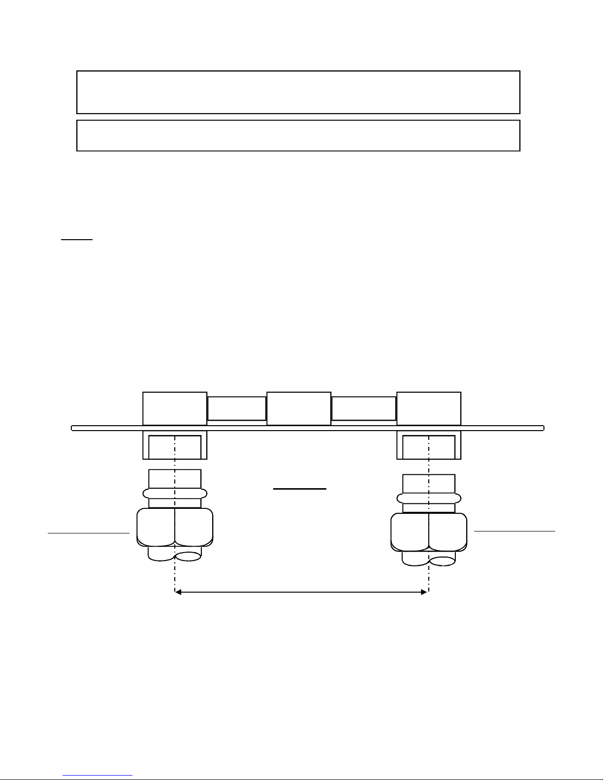
1) This unit is supplied with compression fittings, USE THESE; DO NOT USE TAPERED THREAD PIPE
FITTINGS AND DO NOT SOLDER PIPE TO THE INLET OR OUTLET(SEE FIGURE 1).
2) Ensure that the pipes are correctly aligned with the inlet and outlet bosses in order to avoid excessive stress
on the heater body molding.
NOTE: When soldering pipe joints, remove the unit from the wall. Serious damage can occur if any soldering is
done while pipes are connected to the unit. Run water through the supply pipe to remove all debris from the
pipe before connecting the unit. Failure to do so could cause damage to the flow switch.
3) Install isolating valves (full flow ball valve type) in both the inlet and outlet lines. This allows the unit to be
isolated for maintenance (figure 2).
4) When all plumbing is complete, inspect the system for water leaks at all the plumbing connections. If a water
leak is present take corrective action. If a water leak is at the compression fitting, slowly tighten compression nut
until it the water leak ceases.. Fully open both inlet and outlet BALL VALVES.
Run all hot water outlets fed by this unit, one at a time until the water flow is continuous and free from “gulping”
and all visible air pockets.
HOT WATER
OUTLET
COMPRESSION
FITTING
DO NOT SOLDER
Figure 1
COLD WATER
INLET
COMPRESSION
FITTING
DO NOT SOLDER
1 1/2”
 Loading...