

Page 1
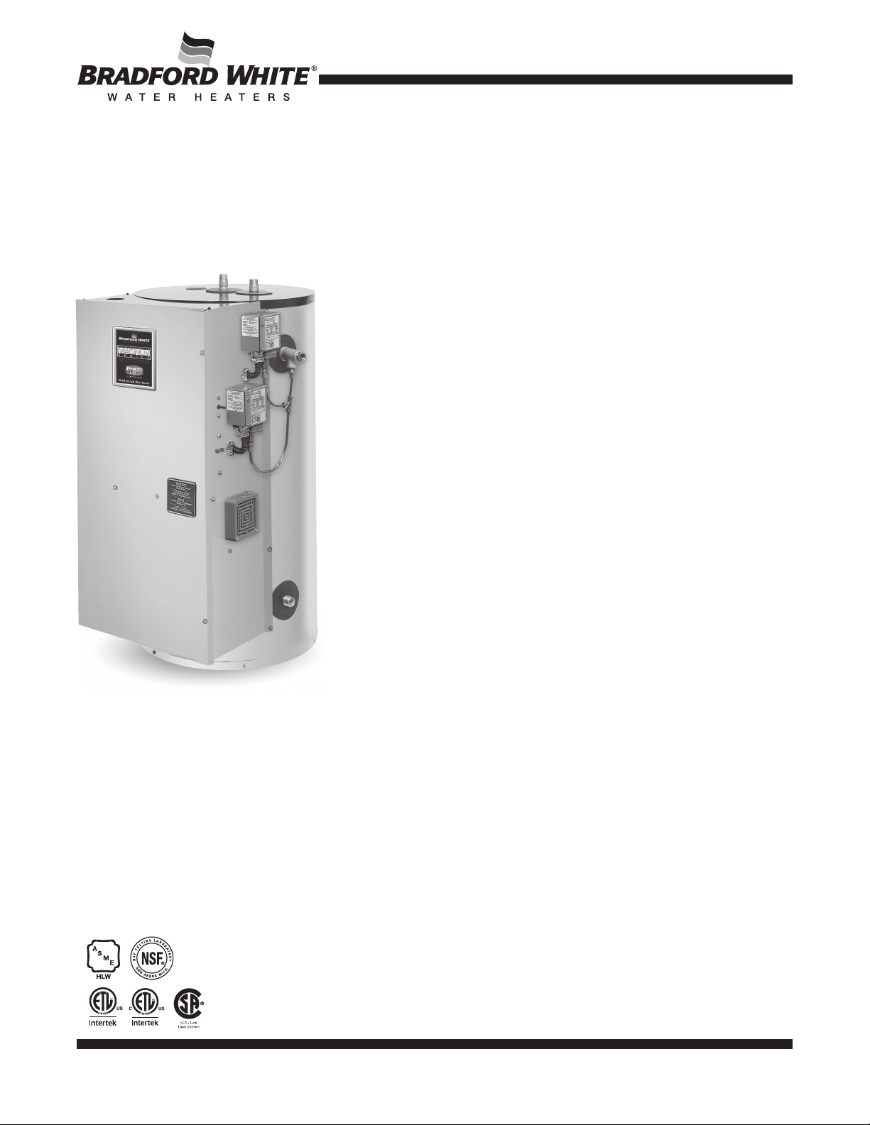
Commercial ASME Electric Water Heaters
The ASME Electric Models feature:
n A.S.M.E. Code Tank Construction—Standard.
n Immersion Thermostats—Immersion type for accurate temperature control
from up to 180°F (82°C) with manual reset high limit control.
n Factory Installed Hydrojet
inlet sediment reducing device helps prevent sediment build up in the tank.
n Vitraglas
®
Lining—An exclusively engineered enamel formula that provides
superior tank protection from the highly corrosive effects of hot water. This
formula (Vitraglas
®
) is fused to the steel surface by firing at a temperature of
over 1600°F (871°C.
n Water Connections— Factory-installed true dielectric fittings extend water
heater life and simplify water line connections.
n Elements—screw in style. Low watt density INCOLOY
minimize dry fire and prevents lime build up.
n Insulation System—Non-CFC foam covers the sides and top of the tank,
reducing heat loss. This results in less energy consumption, improved
efficiencies, and jacket rigidity.
n Protective Magnesium Anode Rod—Provides added protection against
corrosion for long-term, trouble-free service.
n Completely Pre-wired—With pressure lug terminal block eliminating need
for splicing or taping of wires.
n Hand Hole Cleanout—(20 (76L) thru 120 (454L) gallon models only).
n T&P Relief Valve—Installed.
n Low Restriction Brass Drain Valve—Durable tamper proof design.
n NSF Construction Available on All Models.
®
Sediment Reduction System—Cold water
®
material helps to
Photo is of
CEA30-36-3
3 or 5-Year Limited Tank Warranties / 1-Year Limited Warranty on Component Parts.
For more information on warranty, please visit www.bradfordwhite.com
For products installed in USA, Canada, and Puerto Rico. Some states do not allow limitations on warranties.
See complete copy of the warranty included with the heater.
MANUFACTURED UNDER ONE OR MORE OF THE FOLLOWING U.S. PATENTS: 5,682,666; 7,634,976; 5,660,165; 5,954,492; 6,056,542; 6,935,280; 5,372,185; 5,485,879; 5,574,822; 7,971,560; 7,992,526; 6,684,821;
7,334,419; 7,866,168; 7,270,087; 7,007,748; 5,596,952; 6,142,216; 7,699,026; 5,341,770; 7,337,517; 7,665,211; 7,665,210; 7,063,132; 7,063,133; 7,559,293; 7,900,589; 5,943,984; 8,082,888; 5,988,117; 7,621,238;
7,650,859; 5,761,379; 7,409,925; 5,277,171; 8,146,772; 7,458,341; 2,262,174. OTHER U.S. AND FOREIGN PATENT APPLICATIONS PENDING. CURRENT CANADIAN PATENTS: 2,314,845; 2,504,824; 2,108,186;
2,143,031; 2,409,271; 2,548,958; 2,112,515; 2,476,685; 2,239,007; 2,092,105; 2,107,012. Vitraglas
®
and Hydrojet® are registered trademarks of Bradford White® Corporation.
430-B-1219
Page 2
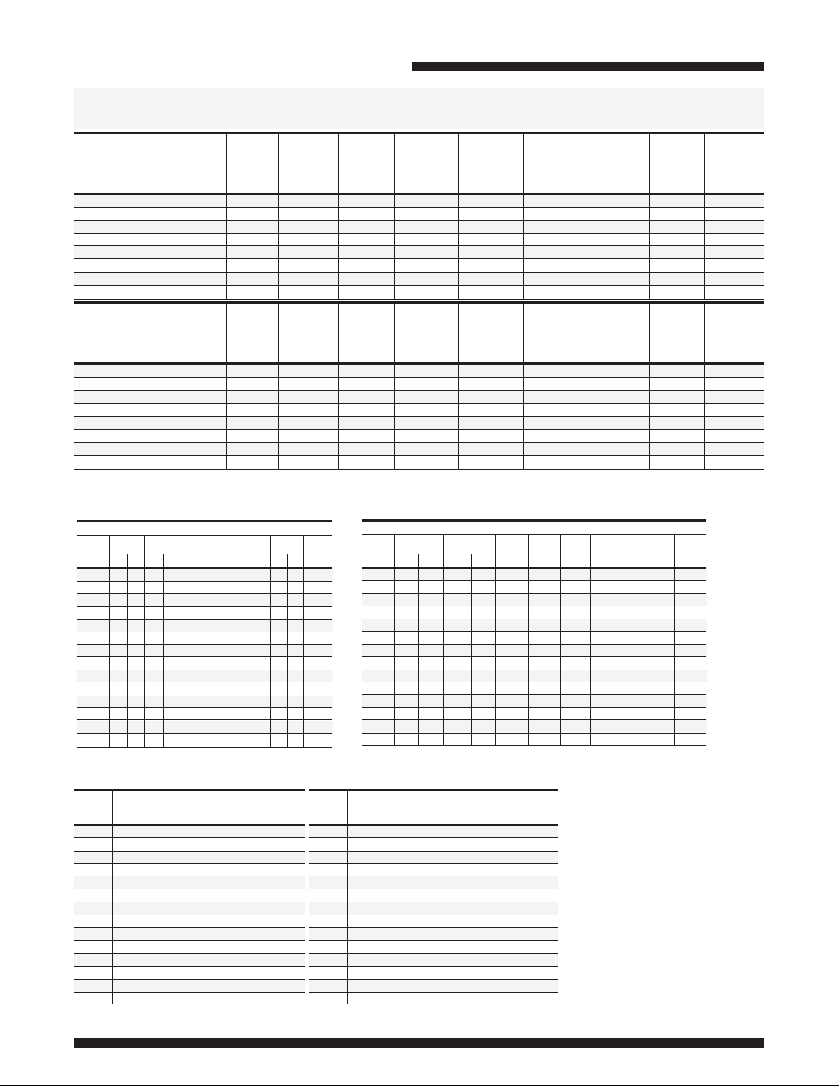
Liters
Commercial Electric Water Heater
Number of Elements (Fused Models)*
Full Load Current Amperes (Fused Models)*
kW Input
ASME Electric Models
Model
Number
CEA6-kW-3
CEA12-kW-3
CEA20-kW-3
CEA30-kW-3
CEA40-kW-3
CEA50-kW-3
CEA80-kW-3
CEA120-kW-3
Model
Number
CEA6-kW-3
CEA12-kW-3
CEA20-kW-3
CEA30-kW-3
CEA40-kW-3
CEA50-kW-3
CEA80-kW-3
CEA120-kW-3
Nominal
Gal.
Capacity
U.S.
Gal.
6
12
19
30
40
48
78
119
Nominal
Capacity
Liter
Min. - Max.
Imp.
Gal. lbs.
5
10
17
25
33
40
65
100
Min. - Max.
23
45
72
114
152
182
295
451
kW
Input
Range
3
3 - 9
3 - 18
13.5 - 36
13.5 - 36
13.5 - 81
13.5 - 81
13.5 - 81
kW
Input
Range
3
3 - 9
3 - 18
13.5 - 36
13.5 - 36
13.5 - 81
13.5 - 81
13.5 - 81
A
Floor to
Top of
Heater
in.
1
17
/8
28
5
27
/8
38
11
48
/16
493/8
607/8
651/8
A
Floor to
Top of
Heater
mm.
435
711
702
965
1237
1254
1546
1654
B
Jacket
Dia.
in.
16
16
20
20
20
24
26
1
30
B
Jacket
Dia.
mm.
406
406
508
508
508
610
661
766
C
Floor to
Hot
Water
Conn.
in.
181/4
29
1
28
/2
39
11
49
/16
497/8
623/8
/4
667/16
C
Floor to
Hot
Water
Conn.
mm.
464
737
724
991
1262
1267
1584
1688
Meet or exceed ASHRAE 90.1b (current standard) C.E.C. Listed
E
Floor to
C/L of
Cold Water
Conn.
in.
1
6
/8
61/8
61/8
61/8
61/8
75/8
75/8
75/8
E
Floor to
C/L of
Cold Water
Conn.
mm.
156
156
156
156
156
194
194
194
Voltage and phase must be specified when ordering. Example: CEA80-18-3, 240 Volt, 3 phase.
Minimum kW inputs for 30 gallons through 119 gallons is 13.5 kW.
F
Floor to
T&P
Conn.
in.
181/16
2815/16
28
1
40
/4
509/16
413/8
527/8
551/4
F
Floor to
T&P
Conn.
mm.
459
735
711
1022
1284
1051
1343
1403
G
Floor to
Top of
Control
Box
in.
17
28
27
38
7
38
/16
471/8
471/8
507/8
G
Floor to
Top of
Control
Box
mm.
432
711
686
965
976
1197
1197
1292
Water
Conn.
NPT
in.
3
/4
3
/4
3
/4
3
/4
3
/4
11/2
11/2
11/2
Water
Conn.
NPT
mm.
19
19
19
19
19
38
38
38
Approx.
Shipping
Weight
83
118
145
180
220
270
335
430
Approx.
Shipping
Weight
kg.
38
54
66
82
100
123
152
195
240V
208V
Phase
Phase
Input
kW
3
6
9
12
13.5
15
18
24
27
30
36
45
54
81
13
1
1
3
3
3
3
3
3
3
3
3
3
3
3
4
6
6
6
6
6
6
6
9
9
9
9
9
9
13
1
3
3
3
3
3
3
4
6
6
6
9
9
9
ASME units with amperage draw of 120 amps or more require factory installed internal fusing. *If the number of elements on non-fused models
is different, it is located in parentheses ( ), following the amp draw.
40
50
3
31
124
140
155
186
248
279
310
372
465
558
852
25
62
50
93
74
99
112
124
149
199
223
248
298
372
447
671
9
12
13.5
15
18
24
27
30
36
45
54
81
6
277V
Phase
1
1
1
3
3
3
3
3
3
3
3
3
3
3
3
4
6
6
6
6
6
6
6
9
9
9
9
9
9
Recovery
GPH Temperature Rise °F
60
70
21
18
41
35
62
53
83
71
93
80
103
89
124
106
164
142
186
160
207
177
248
213
310
266
372
319
558
477
Phase
80
16
31
47
62
70
78
93
124
140
155
186
233
279
418
Phase
3
1
3
3
3
3
3
3
6
6
6
6
9
9
9
90
100
14
28
42
55
62
69
83
110
124
112
138
124
165
149
207
186
248
223
371
334
415V
380V
12
25
37
50
56
62
74
99
3
1
3
3
3
3
3
3
4
6
6
6
9
9
9
480V
Phase
13
1
3
3
3
3
3
3
4
6
6
6
9
9
9
120
10
21
31
41
47
52
62
83
93
103
124
155
186
278
106
133
160
238
140
18
27
35
40
44
53
71
80
89
1
3
3
3
3
3
3
6
6
6
6
9
9
9
9
600V
Phase
3
1
3
3
3
3
3
3
6
6
6
6
9
9
9
kW Input
3
6
9
12
13.5
15
18
24
27
30
36
45
54
81
117
235
352
469
530
587
704
939
1056
1173
1408
1760
2112
3225
208V
Phase
Input
kW
13
3
14
6
29(2)
9
43
12
58
13.5
65
15
72
18
87
24
115
27
130
30
144
36
173
45
216
54
260
81
389
LPH Temperature Rise °C
23
28
34
95
79
189
155
280
235
375
314
424
352
469
390
564
469
753
621
844
704
939
784
1128
939
1408
1173
1692
1408
2540
2112
14
17
25
33
37
42
50
67
75
83
100
125
150
225
Recovery
40
68
132
201
269
303
337
401
538
606
670
806
1007
1208
1806
240V
Phase
13
13
25(2)
38
50
56
63
75
100
113
125
150
188
225
338
45
61
117
106
178
159
235
208
265
235
295
261
352
314
469
416
530
469
587
522
704
625
882
784
1056
939
1582
1404
108
130
195
50
53
33
N/A
8
13
17
19
21
25
33
38
42
50
63
75
113
480V
Phase
13
6
6
13(2)
7
19
11
25(2)
14
28
16
31
18
38
22
50
29
56
32
63
36
75
43
94
54
113
65
169
97
600V
Phase
3
2.8
6
9
12
13
14
17
23
26
29
35
43
52
78
277V
380V
Phase
Phase
1
11
22(2)
33
43(2)
49
54
65
87
97
108
130
163
195
292
117
155
178
197
235
314
352
390
469
587
704
1052
3
5
9
14
18
21
23
27
36
41
46
55
68
82
123
67
78
38
34
79
68
102
132
151
167
201
269
303
337
401
503
606
901
13
14
22
29
32
36
43
58
65
72
87
56
45
95
140
189
212
235
280
375
424
469
564
704
844
1264
400V
Phase
8
9
13
17
20
22
26
35
39
43
52
65
78
117
415V
Phase
Page 3

)
CEA20, CEA30, CEA40
CEA12
CEA6
)
CEA120
CEA80
COLD
(mm)
CEA50
DRAIN
B
ANODE
T&P VALVE
OUTLET
B
CLEANOUT
NOT
AVAILABLE
ON 6/12 GAL.
Commercial Electric Water Heater
OUTLET
(23/45L)
T&P VALVE
C
G
E
(mm)
8"
(203)
DRAIN
75°
75°
T&P
13"
(330)
COLD
DRAIN
A
87°
F
87°
8"
13"
(203)
T&P
(330)
COLD
DRAIN
78°
78°
10"
(254)
14 1/2"
ANODE
T&P
(368
COLD
58°
63°
(305)
12"
18 1/2"
(470)
COLD
52°
13"
(330)
19 1/2"
(495)
56°
COLD
45°
15 1/8"
(384
(562)
22 1/8"
47°
Page 4

Commercial Electric Water Heater
Optional Components
n High and Low Water Pressure Controls—The Controls interrupt the electrical current to the contactor coil when the
pressure settings are exceeded.
n Low Water Level Control—This Control will interrupt the electrical current to the contactor coil when a low water
level condition is sensed inside the water heater tank. When the low water level condition is corrected the control will
automatically sense the new situation and electrical current will again energize the contactor coil. Normal water heater
operation will be resumed.
n Alarm Horn—The Alarm Horn is an option specified when the installation desires an audible signal to immediately sound
an alert when the water heater operation is interrupted for certain faults. Referring to the control circuit wiring diagram,
the alarm will activate when any one of the following events occur:
-- The Hi-Limit control has been tripped
-- The High Water Pressure Control senses excessive pressure
-- The Low Water Pressure Control senses insufficient pressure
-- The Low Water Level Control senses an insufficient quantity of water
n Modulating Controls—Heating element sequencers are available in order to stage the activation of the heating
elements thereby, reducing the inrush current to the water heater. The sequencers will control one or two contactor coils
depending upon the water heater voltage, phase, and kW.
n Electrical Door Lock—An electrical door lock is offered in order to secure the access to the water heater control
cabinet. This device will lock the control cabinet door when the 120VAC control circuit voltage is applied to it.
n Temperature and Pressure Gauge—Displays approximate temperature of the water and approximate pressure inside
the tank.
n BMS Relays—Allows BMS to supply power to the water heater on and off and view if the elements are in operation
-- Relay 1- When energized by the BMS supply voltage, this will allow water heater operation (enable/disable)
-- Relay 2- Sends signal to BMS to show if the elements are in operation or not.
Sample Specification
The water heater shall be a Bradford White model with a rated storage capacity of not less than_______gallons (_______liters), a minimum
kW input of _______kW (_______ BTU/Hr.), a minimum recovery of _______GPH (_______ LPH). The tank shall be Vitraglas
®
lined and have a
bolted hand hole cleanout. The tank shall have _______magnesium anode rods installed in separate tank head couplings. The heater shall
have 3” Non-CFC foam insulation, and come equipped with an ASME rated T&P relief valve, a cold water inlet Hydrojet
®
Sediment Reduction
System. It shall be design certified by ETL for 180ºF (82ºC) application, either with or without a separate storage tank, and comply with
state and local codes and ordinances.
General
All electric water heaters are certified at 300 PSI test pressure (2068 kPa) and 150 PSI working pressure (1034 kPa). All models are design
certified by ETL, for up to 180°F (82°C) application as an Automatic Storage Heater, and an Automatic Circulating Tank Heater. As an
Automatic Storage Heater, all models are complete, self-contained water heating systems. It needs no separate storage tank, pump, wiring
or elaborate piping network. When equipped with a mixing valve, it will supply 180°F (82°C) sanitizing and lower temperature general purpose
hot water simultaneously. These models can be used either as a single unit or in multiples connected in series or parallel (recommended).
Dimensions and specifications subject to change without notice in accordance with our policy of continuous product improvement.
For field service, contact your professional installer or local Bradford White sales representative.
Ambler, PA
Sales 800-523-2931 n Fax 215-641-1612
Technical Support 800-334-3393
Warranty 800-531-2111
International: Telephone 1-215-641-9400 n Email international@bradfordwhite.com / www.bradfordwhite.com
n
n
Email techserv@bradfordwhite.com
Email warranty@bradfordwhite.com
©2019, Bradford White Corporation. All rights reserved.
Printed in U.S.A.430-B-1219
 Loading...