

Bradford White 120T400, 120T500 Installation & Operation Manual
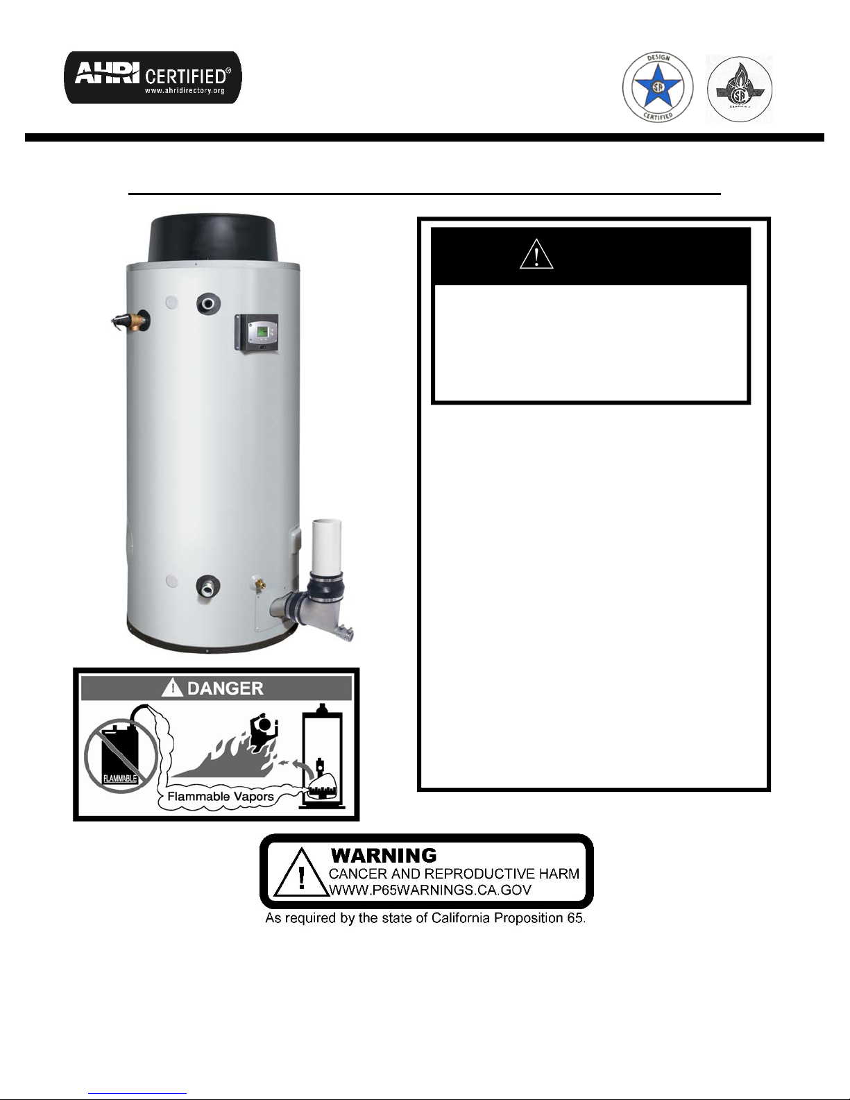
HIGH EFFICIENCY COMMERCIAL GAS WATER HEATER
If the information in these
instructions is not followed exactly,
a fire or explosion may result
causing property damage, personal
injury or death.
- Do not store or use gasoline or other
flammable vapors and liquids in the
WARNING
vicinity of this or any other appliance.
- WHAT TO DO IF YOU SMELL GAS
Do not try to light any appliance.
Do not touch any electrical switch;
do not use any phone in your
building.
Immediately call your gas supplier
- For your family’s comfort, safety and
from a neighbor’s phone. Follow
the gas supplier’s instructions.
If you cannot reach your gas
supplier, call the fire department.
convenience, it is recommended this
water heater be installed and
serviced by a plumbing professional.
INSTALLATION & OPERATION MANUAL
PLACE THESE INSTRUCTIONS ADJACENT TO WATER HEATER AND NOTIFY OWNER TO KEEP FOR FUTURE REFERENCE
WITH TROUBLESHOOTING GUIDE
238-53506-00A REV 1/19

CAUTIO
2
SECTION I: IMPORTANT INFORMATION
READ CAREFULLY
This gas-fired water heater is design certified by CSA International under the American National Standard, Z21.10.3
(as indicated on the rating plate) and CAN/CGA 4.3-M (as indicated on the rating plate) available from CSA Standards
Association, 5060 Spectrum Way, Mississauga, Ontario, CANADA L4W 5N6.
This water heater must be installed in accordance with local codes. In the absence of local codes, it must be installed
in compliance with the National Fuel Gas Code (ANSI Z223.1-Latest Edition), or in Canada CAN/CGA B149.1 Natural
Gas Installation Code (Latest Edition) or CAN/CGA B149.2 Propane Installation Code (Latest Edition).
The following terms are used throughout this manual to bring attention to the presence of hazards at various risk
levels, or to important information concerning product life.
Indicates an imminently hazardous situation, which, if
not avoided, will result in death, serious injury or
substantial property damage.
Indicates a potentially hazardous situation, which, if
not avoided, could result in death, serious injury or
substantial property damage.
WARNING
This water heater has a limited warranty. The warranty for this water heater is valid only if the water heater has been
installed, maintained and operated in accordance with these instructions.
NOTICE
SECTION I: IMPORTANT INFORMATION............2
TABLE OF CONTENTS
Indicates potentially hazardous situation, which, if not
avoided, may result in moderate or minor injury or
property damage.
Indicates special instructions on installation, operation
or maintenance, which are important but not related to
personal injury hazards.
SECTION VII: GAS CONNECTIONS....................34
NOTICE
N
SECTION II: SPECIFICATIONS...............................5
SECTION III: GENERAL INFORMATION...............6
SECTION IV: INSTALLATION INSTRUCTIONS..9
SECTION V: WATER CONNECTIONS................15
SECTION VI: VENTING..........................................17
SECTION VIII: ELECTRICAL CONNECTIONS...36
SECTION IX: OPERATING INSTRUCTIONS......36
SECTION X: MAINTENANCE................................45
SECTION XII: PARTS LIST....................................56
DANGER
y
g
y
g
y
g
3
DO NOT store or use gasoline or other flammable, combustible, or corrosive vapors and/or liquids in the vicinity of this or
other appliance.
an
DO NOT install any damaged venting system components. If damage is evident then please contact the supplier where
the water heater was purchased, or the manufacturer listed on the ratin
Use only vent terminals provided or factory authorized terminals for venting this water heater.
This water heater is equipped with an adjustable thermostat to control water temperature. Hot water temperatures
required for automatic dishwasher and laundry use can cause scald burns resulting in serious personal injury and/or
death. The temperature at which injury occurs varies with the person’s age and the time of exposure. The slower
response time of disabled persons increases the hazards to them. NEVER allow small children to use a hot water tap,
or to draw their own bath water. NEVER leave a child or disabled person unattended in a bathtub or shower.
Failure to properly install the vent and air intake (if applicable) system could result in property damage, personal injury,
or death
plate for replacement parts.
WARNING
Improper installation, adjustments, alteration, service or maintenance can cause property damage, personal injury or
loss of life. Failure to follow all instructions in the proper order can cause personal injury or death. Read and understand
all instructions, including all those provided with the appliance before installing, starting-up, operating, maintaining or
servicing this appliance. Keep this manual and literature in legible condition with this water heater for reference by
owner and service technician.
This water heater requires regular maintenance and service to operate safely. Follow the instructions contained in this
manual.
Installation, maintenance, and service must be performed only by a qualified, skilled and knowledgeable installer or
service provider.
Installation is not complete unless a temperature and pressure relief valve is installed into the proper location at the top
of this water heater.
It is the responsibility of the installing contractor to see that all controls are correctly installed and are properly operating
when the installation is complete.
This water heater is suitable for installation on combustible flooring. Do not install water heater directly on carpeting.
DO NOT operate this water heater without first being certain it is filled with water.
DO NOT tamper with or alter the water heater and/or controls.
DO NOT operate water heater with jumpered or absent controls or safety devices.
DO NOT operate water heater if any external part has been under water. Immediately call a qualified service agency to
inspect the appliance and to replace an
DO NOT attempt to use this water heater with any gas other than the type listed on the rating plate. Do not attempt to
convert this water heater for use with a gas other than the type for which it is equipped. Failure to use the proper gas
can create an unsafe condition resulting in property damage, bodily injury, or death. Consult your local gas supplier or
as company if there are any questions.
DO NOT operate this water heater if the input rate exceeds the rate shown on the water heater rating plate.
This water heater contains very hot water under high pressure. Do not unscrew any pipe fittings nor attempt to
disconnect any components of this water heater without positively assuring the water is cool and is not under pressure.
Always wear protective clothing and equipment when installing, starting up or servicing this water heater to prevent scald
injuries. Do not rely on the temperature gauges to determine the temperature. Do not touch any components unless
are cool.
the
This water heater must be properly vented and connected to an approved vent system in good condition. DO NOT
operate water heater with the absence of an approved vent system. A clean and unobstructed vent system is
necessary to allow noxious fumes that could cause injury or loss of life to vent safely and will contribute toward
maintainin
the water heater’s efficiency.
part of the control system including gas controls, which has been under water.
WARNING
y
y
(
y
4
This water heater needs fresh air for safe operation and must be installed so there are provisions for adequate
combustion and ventilation air. Insufficient air supply will cause a recirculation of combustion products resulting in
contamination that may be hazardous to life. This will result in carboning or sooting of the combustion chamber, burners,
and flue tubes and creates a risk of asph
This water heater requires its own separate venting system. DO NOT connect the exhaust vent into an existing vent
pipe or chimne
Flammable items, pressurized containers or any other potential fire hazardous articles must never be placed on or
adjacent to the water heater. Open containers of flammable material should not be stored or used in the same room with
this water heater.
Insulation blankets are not required for this water heater. This water heater meets or exceeds the ASHRAE/IES 90.1b
latest edition) standards with respect to insulation and standby loss requirements.
Hydrogen gas can be produced in an operating water heater that has not had water drawn from the tank for a long
period of time (generally two weeks or more). Hydrogen gas is extremely flammable. To prevent the possibility of injury
under these conditions, we recommend the hot water faucet to be open for several minutes at the kitchen sink before
you use any electrical appliance which is connected to the hot water system. If hydrogen is present, there will be
unusual sounds such as air escaping through the pipes as hot water begins to flow. Do not smoke or have open flame
near the faucet at the time it is open.
Prior to connecting the gas supply line to a gas fired water heater, ensure that the gas supply line does not have
moisture/water or dirt/scale inside the gas line. Commonly this check is done at the lowest point in the gas distribution
stem prior to gas burning appliances.
s
Do not use this appliance if any external part to the tank has been submerged in water. You should contact a qualified
service technician to inspect the appliance and to replace any part of the control system including the combination gas
control which has been submerged in water. See the Gas Connections section of this manual before servicing or
replacing a water heater that has had any external part to the tank submerged in water.
.
xiation.
WARNING
Liquefied petroleum gases/propane gas is heavier than air and will remain at floor level if there is a leak. Basements,
crawl spaces, closets and areas below ground level will serve as pockets for accumulation of leaking gas. Before
lighting, smell all around the appliance area for gas. Be sure to smell next to the floor.
IF YOU SMELL GAS:
DO NOT try to light any appliance.
DO NOT touch any electric switch; do not use any telephone in your building.
Immediately call your gas supplier from a telephone in another building. Follow the gas supplier’s instructions.
If you cannot reach your gas supplier, call the fire department.
DO NOT OPERATE THE APPLIANCE UNTIL THE LEAKAGE IS CORRECTED!
WARNING
To comply with NSF requirements this water heater must be sealed to the floor with sealant, in a smooth and easily
cleanable way.
SECTION II: SPECIFICATIONS
5
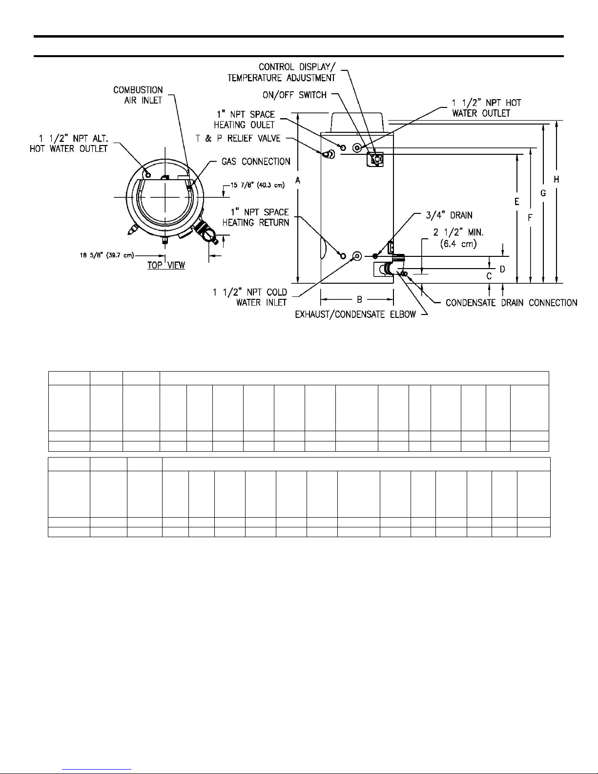
Figure 1. Dimensional Layout.
Table 1. Specifications.
DIMENSIONS (INCHES)
D
Floor to
Inlet
Water
Conn.
Model No.
Input
Rate
BTU/h
Storage
Capacity
U.S.
Gallons
A
Height B Dia.
C
Floor to
Vent
Outlet
120T400 399,999 119 77 1/8 33 6 ¾ 12 ¼ 58 ½ 61 ¼ 71 73 ¾ 1 ½ 1 1 1 1120
120T500 499,999 119 77 1/8 33 6 ¾ 12 ¼ 58 ½ 61 ¼ 71 74 7/8 1 ½ 1 1 1 1135
DIMENSIONS (MILLIMETERS)
C
Floor to
Vent
Outlet
Floor to
Inlet
Water
Conn.
Model No.
Input
Rate
KW
Storage
Capacity
Liter
A
Height B Dia.
120T400 399,999 450 1959 838 171 311 1486 1556 1803 1873 38 25 25 25 508
120T500 499,999 450 1959 838 171 311 1486 1556 1803 1902 38 25 25 25 515
D
E
Floor to
T&P
Valve
Conn.
E
Floor to
T&P
Valve
Conn.
F
Floor to
Outlet
Water.
Conn.
F
Floor to
Outlet
Water
Conn.
G
Floor to Air
Intake
G
Floor to Air
Intake
H
Floor to
Gas
Conn.
H
Floor to
Gas
Conn.
Front
Water
Conn.
Dia.
Front
Water
Conn.
Dia.
Space
Heating
Conn.
Dia.
Space
Heating
Conn.
Dia.
Gas
Conn.
Dia.
Gas
Conn.
Dia.
Relief
Valve
Open
Relief
Valve
Open.
Shipping
Wt.
(LBS)
Shipping.
Wt.
(KG)

SECTION III: GENERAL INFORMATION
6
FEATURES
This water heater contains the following features:
MAIN POWER ON/OFF SWITCH
The front panel of this water heater has an ON/OFF switch, which has markings to indicate when the main power is turned
on to indicate power to the water heater.
COMBUSTION SYSTEM
This water heater is equipped with a self-compensating negative pressure pre-mix combustion system. As the blower
operates, air is drawn in through the air intake and into a venturi, which pulls gas from the gas valve. The gas and air are
then mixed in the combustion blower and sent through the transition tube into the burner. The Direct Spark Ignition
System (DSI) then ignites the gas/air fuel mixture to produce flue products (combustion). The flame sensor signals the
ignition control board (described below), that a flame is present.
HONEYWELL INTEGRATED CONTROL
Consists of a control board and a water heater display. An attractive digital water heater display is on the top front of the
water heater for precisely setting and displaying the temperature setpoint and monitoring the status of the water heater.
Pressing the temperature UP and DOWN buttons changes the temperature setpoint. The temperature format may be
displayed in degrees F or degrees C. The water heater display will show diagnostic codes in the event the water heater
needs servicing. The temperature readings of the tank sensor can be monitored in Service Mode. Also, in Service Mode,
the display can show up to 10 previous error codes to further aid in servicing the water heater.
The single control board has plug in wiring harnesses to reduce the chance of mis-wiring. The control board controls the
combustion blower, ignition timings, and gas valve to control the combustion system in order to maintain the desired tank
temperature. The sequence of operation is described in detail in the Diagnostic Section at the back of this Installation and
Operation Manual.
ADJUSTABLE THERMOSTAT
This water heater is equipped with an adjustable thermostat as part of the Integrated Control System to control water
temperature. Hot water temperatures required for automatic dishwasher and laundry use can cause scald burns resulting
in serious personal injury and/or death.
The temperature may be adjusted from about 100°F (38°C) to about 180°F (82°C). The thermostat was adjusted to 100°F
(38°C) before the water heater was shipped from the factory. It is recommended that lower temperatures be used to
avoid the risk of scalding. Refer to the “Warnings” and the section on SCALDING in “Section V: Water Connections”. It is
further recommended, in all cases, that the water temperature be set for the lowest temperature, which satisfies your hot
water requirements for the installation. This will also provide the most energy efficient operation of the water heater and
minimizes scale formation.
Setting the water heater temperature at 120°F (49°C) will reduce the risk of scalds. Some states require setting lower
temperatures for specific installations.
The top immersion well of the single sensor control also contains a redundant sensor for the high limit (energy cutoff).
The high limit circuit interrupts the main burner gas flow should the water temperature exceed approximately 200°F
(93°C). Error code “80” will be shown on the water heater control display if the high limit temperature has been exceeded.
Should the high limit switch activate, it must be manually reset. This should only be done by a service technician after the
cause of overheating has been corrected. Refer to the section on “Accessing Service Mode on the Display” in the
Diagnostic section of this Installation and Instruction Manual.
Contact your qualified installing contractor, service provider or manufacturer listed on the rating plate if continued high
limit operation occurs.
SERVICE PANELS
The service panels are located behind the service panel access covers, which are located around the exhaust elbow side
of the water heater. These panels contain a pressure switch that monitors the pressure in the exhaust pipe in case the
vent system becomes blocked. An exhaust high limit switch is used to monitor the ambient temperature of the exhaust
collector. This is a manually re-settable switch. If this switch continues to trip, please contact an authorized service
agency.
LATCHES
The latches allow easy access for servicing the water heater from the top. Simply open the three latches and lift surround
up for servicing. No tools are required to obtain access to the top of the water heater. Then replace the surround and relatch when the service has been completed.
TEMPERATURE AND PRESSURE RELIEF VALVE
7
WARNING
Keep clear of the combination temperature and pressure relief valve discharge line outlet. The discharge may
be hot enough to cause scald injury. The water is under pressure and may splash.
For protection against excessive temperatures and pressure, install temperature and pressure protective equipment
required by local codes, but not less than a combination temperature and pressure relief valve certified by a nationally
recognized testing laboratory that maintains periodic inspection of production of listed equipment or materials as
meeting the requirements of the Standard for Relief Valves and Automatic Gas Shutoff Devices for Hot Water Supply
Systems, ANSI Z21.22 and the Standard CAN1-4.4 Temperature, Pressure, Temperature and Pressure Relief Valves
and Vacuum Relief Valves. The combination temperature and pressure relief valve must be marked with a maximum
set pressure not to exceed the maximum working pressure of the water heater. The combination temperature and
pressure relief valve rating must not be less than the hourly rating of the water heater.
Install the combination temperature and pressure relief valve into the opening provided and marked for this purpose on
the water heater.
Note: Some models may already be equipped or supplied with an installed combination temperature and pressure
relief valve. Verify that the combination temperature and pressure relief valve complies with local codes. If the
combination temperature and pressure relief valve does not comply with local codes, replace it with one that does.
Follow the installation instructions above on this page.
Install a discharge line so that water discharged from the combination temperature and pressure relief valve will exit
within six (6) inches (15.2 cm) above, or any distance below the structural floor and cannot contact any live electrical
part. The discharge line is to be installed to allow for complete drainage of both the combination temperature and
pressure relief valve and the discharge line. The discharge opening must not be subjected to blockage or freezing.
DO NOT thread, plug or cap the discharge line. It is recommended that a minimum clearance of four (4) inches
(10.0 cm) be provided on the side of the water heater for servicing and maintenance of the combination temperature
and pressure relief valve.
Do not place a valve between the combination temperature and pressure relief valve and the tank!
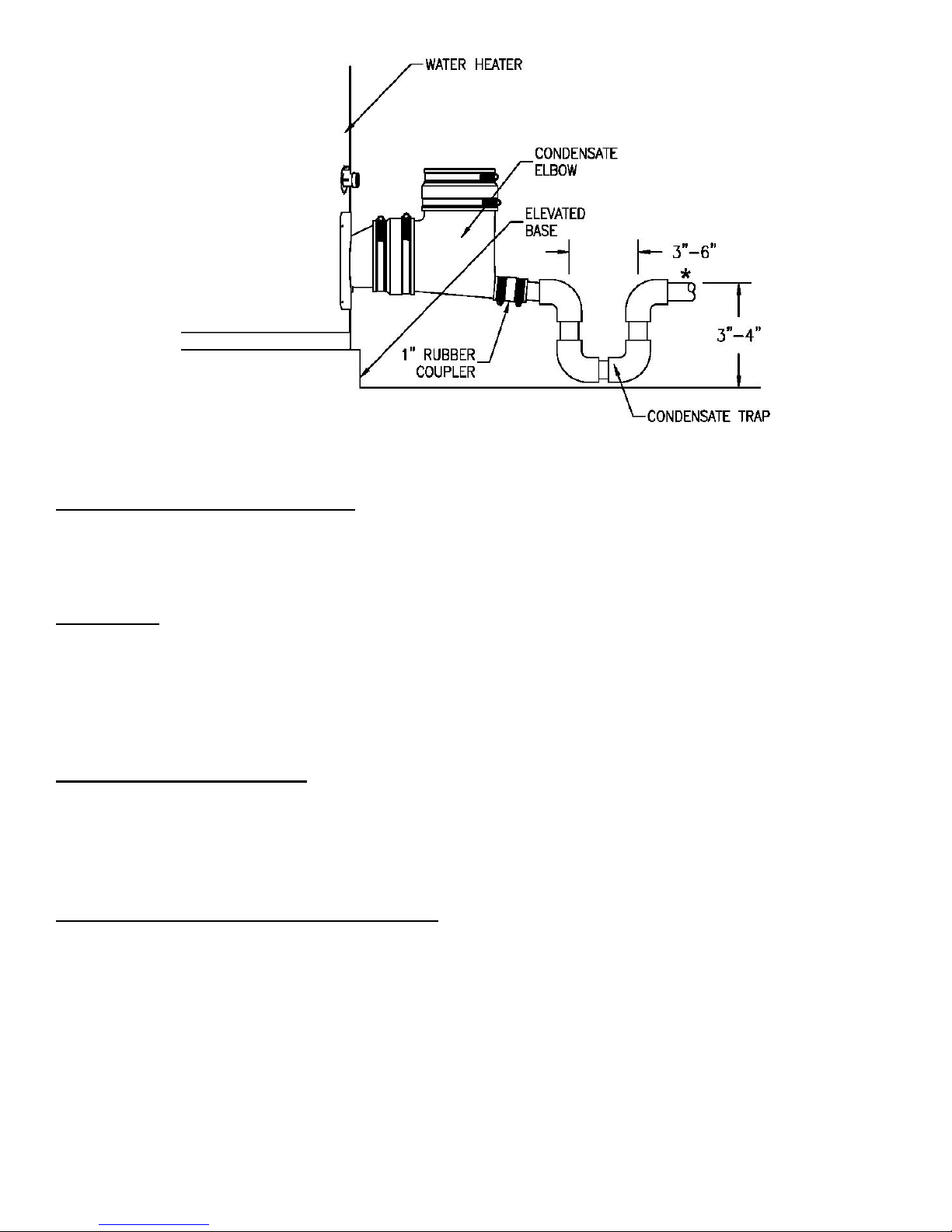
CONDENSATE DRAIN
The water heater should either be raised several inches above the floor on a concrete slab or use a low-profile
condensate pump to allow free drainage of condensate from the elbow drain fitting. This water heater is a condensing
type unit and requires a drain to be located in close proximity to allow the condensate to drain safely. The condensate
drains from the unit at the field installed exhaust condensate elbow located near the bottom of the unit. Using 1” PVC
create a drain trap as shown in figure 2 which connects to condensate elbow using the supplied rubber coupler. Also use
1” PVC from drain trap to the drain. Make sure the condensate drains line slopes down, away from the water heater at
least 1/8" per foot toward the drain. The condensate drain pipe must not be routed through an area subject to below
freezing temperatures. The condensate build-up will block the exhaust outlet, which will cause improper operation. Refer
to Figure 2 for the proper connection of an elbow to the drain outlet and a condensate trap.
Failure to properly install the condensate drain as directed above, as well as shown in Figure 2 may result in damage
and/or cause improper operation of to the water heater. Any damage resulting from failure to install the condensate
drain as directed will not be covered by the warranty.
CAUTION
8
Figure 2. Condensate Elbow with Trap.
*Outlet of condensate trap must not be higher than outlet of condensate elbow.
CONDENSATE NEUTRALIZATION
The condensate draining from the water heater’s covered in this manual have PH levels between 4.3 and 5.0. Install a
commercially available neutralizing kit if required by local code.
NOTE: Lower PH levels are acidic. Do not connect a metal drain line, such as copper, to the water heater for this reason.
CLEANOUT
All models are equipped with a cleanout opening to aid in removal of hard water deposits from the tank bottom. If this
water heater operates under hard water conditions, the following should be performed at least every 3 months: Turn off
water supply and drain the water heater. Remove the cleanout jacket cover and tank cover. When cleaning the tank,
care must be taken to avoid trying to break deposits loose as this could damage the glass lining and shorten the life of the
water heater. After cleaning, re-install the cleanout tank cover and jacket cover, and refill with water. Refer to the section,
“Section X – Maintenance” in this Installation and Operation manual for the procedures for filling and draining the water
heater.
POWERED ANODE SYSTEM
The powered anode system provides corrosion protection to the tank by supplying a low voltage current to the titanium
anode rods and then periodically comparing this current with the potential between the anode rod and tank wall to make
corrections. The powered anode system is designed to extend the tank life without requiring anode rod replacement. The
powered anode system consists of titanium powered anode rods and a powered anode control module located on the
control panel. More details on the powered anode system are in “Section X: Maintenance” in this Installation and
Operation Manual.
DISHWASHING MACHINE REQUIREMENTS
All dishwashing machines meeting the National Sanitation Foundation requirements are designed to operate with water
flow pressures between 15 and 25 pounds per square inch. Flow pressures above 25 pounds per square inch, or below
15 pounds per square inch, will result in improperly sanitized dishes.
The National Sanitation Foundation also recommends circulation of 180°F water. Where this is done, the circulation
should be very gentle so that it does not cause any unnecessary turbulence inside the water heater. The circulation
should be just enough to provide 180°F water at the point of take-off to the dishwashing machine. Adjust flow by means
of the valve in the circulation line.
SECTION IV: INSTALLATION INSTRUCTIONS
9
INSTALLATION OF THIS WATER HEATER REQUIRES ABILITY EQUIVALENT TO THAT OF A LICENSED
TRADESMAN IN THE FIELD INVOLVED. PLUMBING, AIR SUPPLY, VENTING, GAS SUPPLY AND
ELECTRICAL WORK ARE REQUIRED
DO NOT ATTEMPT TO LIGHT ANY GAS APPLIANCE IF YOU ARE NOT CERTAIN OF THE FOLLOWING:
Liquefied petroleum gases/propane gas and natural gas have an odorant added by the gas supplier that aids in
detection of the gas.
Most people recognize this odor as a “sulfur” or “rotten egg” smell.
Other conditions, such as “odorant fade” can cause the odorant to diminish in intensity, or “fade”, and not be as
readily detectable.
If you have a diminished sense of smell or are in any way unsure of the presence of gas, immediately contact
your gas supplier from a telephone in another building.
Gas detectors are available. Contact your gas supplier or plumbing professional for more information.
Liquefied petroleum gases/propane gas is heavier than air and will remain at floor level if there is a leak. Basements,
crawl spaces, closets and areas below ground level will serve as pockets for accumulation of leaking gas. Before
lighting, smell all around the appliance area for gas. Be sure to smell next to the floor.
IF YOU SMELL GAS:
Do not try to light any appliance.
Do not touch any electric switch; do not use any telephone in your building.
Immediately call your gas supplier from a telephone in another building. Follow the gas supplier’s instructions.
If you cannot reach your gas supplier, call the fire department.
DO NOT OPERATE THE APPLIANCE UNTIL THE LEAKAGE IS CORRECTED!
This water heater must be located in an area where leakage of the tank, water line connections, or the combination
temperature and pressure relief valve will not result in damage to the area adjacent to the water heater or to lower
floors of the structure. When such locations cannot be avoided, a suitable drain pan must be installed under the water
heater. The drain pan depth must be suitable for draining and collecting water and have a minimum length and width
of at least four (4) inches (10.0 cm) measured from the jacket of the water heater. The drain pan, as described above,
can be purchased from your plumbing professional. The drain pan must be piped to an adequate drain. The piping
must be at least 3/4 inch (2.0 cm) in diameter and pitched for proper drainage.
Anode rods have been installed in the tank head of the water heater to extend tank life. The removal of these anodes,
except for inspection and/or replacement, will nullify the warranty. In areas where water is unusually active, an odor may
occur at the hot water faucet due to a reaction between the anode and the impurities in the water. If this should happen,
alternative anodes may be purchased from the supplier that installed this water heater. This will minimize the odor while
protecting the tank. Additionally, the water heater should be flushed with appropriate dissolvers to eliminate any bacteria.
Note: For California installation this water heater must be braced, anchored, or strapped to avoid falling or
moving during an earthquake. See instructions for correct installation procedures. Instructions may be obtained
from the DSA Headquarters Office: 1102 Q Street, Suite 5100, Sacramento CA 95811.
This water heater MUST be installed indoors out of the wind and weather.
This water heater MUST NOT be installed in any location where gasoline or flammable vapors are likely to be
present, unless the installation is such to eliminate the probable ignition of gasoline or flammable vapors.
WARNING
WARNING
UNPACKING/INSPECTION
10
1. Inspect carefully for any signs of damage.
2. All equipment is carefully manufactured, inspected and packed.
3. Any claims for damage or shortage in shipment must be filed immediately with the shipper and noted on the Bill of
Lading.
NOTICE
The vent terminal that is supplied with this water heater are stored at the top in the Combustion Assembly
Compartment. The condensate elbow and rubber couplers are secured to the bottom of the crating.
LOCATE WATER HEATER
1. Locate water heater in front of final position before removing crate.
2. LOCATE so that venting connections will be short and direct.
3. THIS WATER HEATER IS SUITABLE FOR INSTALLATION ON COMBUSTIBLE FLOOR. Do not install this
water heater directly on carpeting. If the water heater is to be installed on carpeting, it must be installed on top of
a metal or wood panel extending beyond the full width and depth of the appliance by at least three 3 inches (7.6
cm) in any direction or, if the appliance is to be installed in an alcove or closet, the entire floor must be covered by
the panel.
4. FOR BASEMENT INSTALLATION, provide a solid level elevated base such as concrete or other suitable pad to
raise the water heater at least 3” to provide a slope of 1/8” to 1/4” per foot for the condensate line to a suitable
drain.
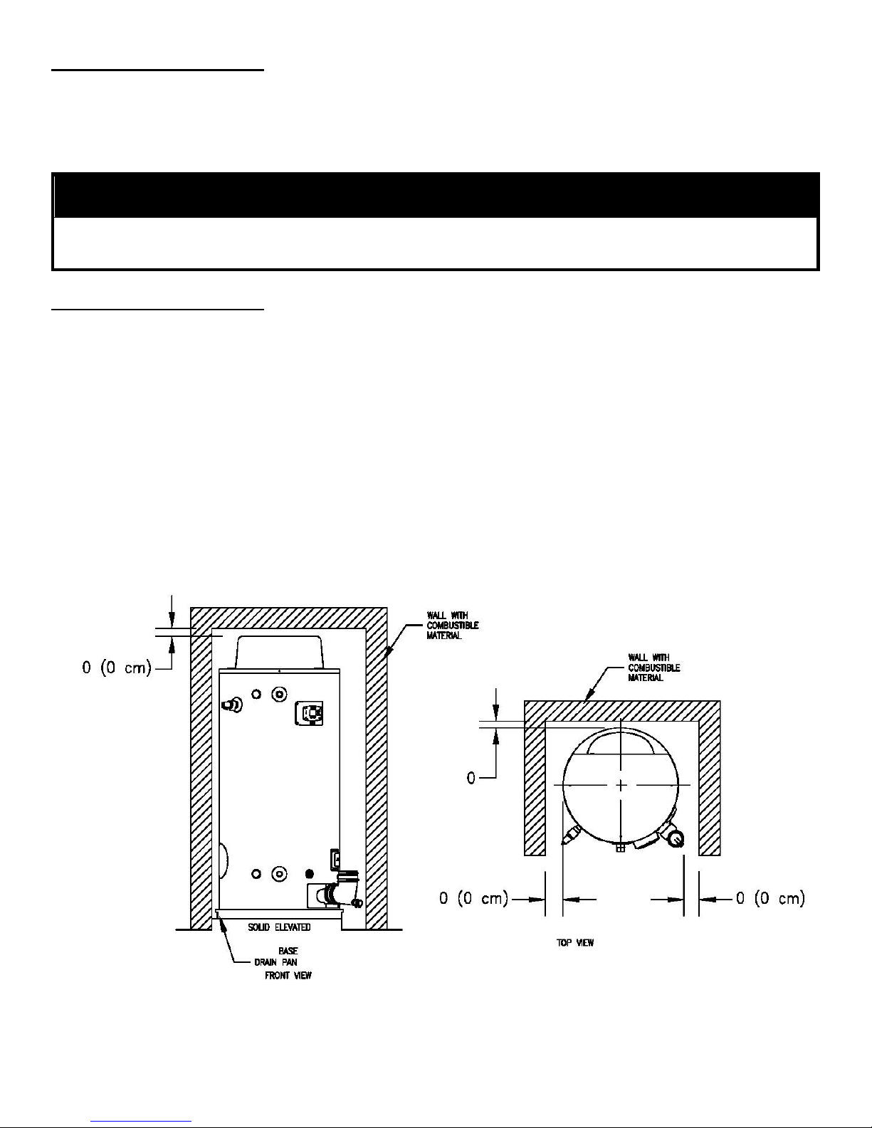
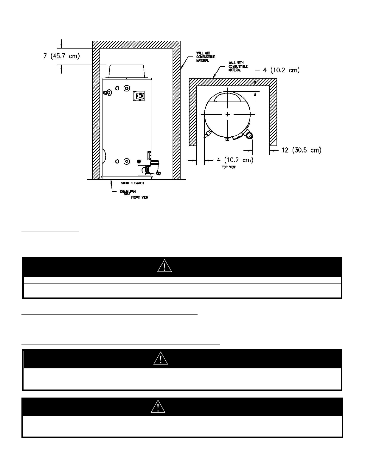
5. Minimum clearance to combustible material is 0” for the Top, Sides, and Rear of this water heater. However, it is
recommended that at least 18” from the Top, 24” from the Front, 4” for the Left Side and Rear, and 12”
from the Right Side Exhaust Elbow of the water heater be provided for servicing. Clearance for servicing
may be reduced down to minimum clearance to combustible material, but service time and effort may be greatly
increased.
Figure 3a. Minimum Clearance to Combustible Material.
g
11
Figure 3b. Recommended Minimum Clearances for Service Access.
REMOVE CRATE
1. Remove all banding and pry off crate sides carefully so as not to damage the water heater.
2. Carefully roll/lift the water heater from the crate base.
CAUTION
Do not drop water heater. Do not bump water heater jacket against floor.
Do not bump exhaust vent pipe against crate or other objects. This will damage the heater and cause it to be
inoperable or create nuisance problems.
MOVE WATER HEATER TO PERMANENT POSITION
1. Move the water heater to permanent position by sliding or walking.
2. Place drain pan underneath water heater.
INSTALL TEMPERATURE AND PRESSURE RELIEF VALVE (if not already installed).
DANGER
Temperature setting should not exceed safe temperature at fixtures. See water temperature control warning in
Section V, “Water Connections”. If higher preheat temperatures are necessary to obtain adequate booster output, add
an ASSE approved mixing device for hot water supplied to fixtures.
Temperature and pressure relief valve discharge piping must be piped near floor to eliminate potential of severe burns.
Do not pipe in any area where freezing could occur. Do not install any shut-off valves, plugs or caps to the
temperature and pressure relief valve or pipin
WARNING
.
CAUTION
y
12
If the building cold water supply has a back-flow preventer, check valve or water meter with check valve, provisions for
thermal expansion of water in the hot water s
stem must be provided.
LOCATION
KEEP APPLIANCE AREA CLEAR AND FREE OF COMBUSTIBLE MATERIALS, GASOLINE AND OTHER
FLAMMABLE VAPORS AND LIQUIDS.
1. This water heater must be located in an area where the general public does not have access to set temperatures.
AIR REQUIREMENTS
1. Do not obstruct the flow of combustion and ventilating air.
2. For safe operation, adequate air is needed for combustion and ventilation. Sooting may result in serious damage
to the water heater and risk of fire or explosion. It can also create a risk of asphyxiation. Such a condition often
will result in a yellow, luminous burner flame, causing carboning or sooting of the combustion chamber, burner
and flue tubes.
MECHANICAL EXHAUSTING OF ROOM AIR
1. Where an exhaust fan is installed in the same room with this water heater and combustion air is drawn from
inside the room, sufficient openings for air must be provided in the walls. UNDERSIZED OPENINGS WILL
CAUSE AIR TO BE DRAWN INTO THE ROOM THROUGH THE WATER HEATER’S VENTING SYSTEM,
CAUSING POOR COMBUSTION THAT MAY BE HAZARDOUS TO LIFE. SOOTING MAY RESULT IN
SERIOUS DAMAGE TO THE WATER HEATER AND RISK OF FIRE OR EXPLOSION, WHICH CAN ALSO
CREATE A RISK OF ASPHYXIATION. Refer to local codes and /or National Fuel Gas Code for proper air
opening sizing.
UNCONFINED SPACE
1. In buildings of conventional frame, brick or stone construction, unconfined spaces may provide adequate air for
combustion and ventilation.
2. If the unconfined space is within a building of tight construction (buildings using the following construction:
weather stripping, heavy insulation, caulking, vapor barrier, etc.), air for combustion and ventilation must be
obtained from outdoors. This may be accomplished by piping air directly to the water heater from outside or
providing opening or ducts in the wall. The installation instructions for confined spaces in tightly constructed
buildings must be followed to ensure adequate air supply.
CONFINED SPACE (Spaces having less than 50 ft3/1000 BTU (1.4m3/0.29 kW-hr.)
1. When drawing combustion air from inside a conventionally constructed building to a confined space, such a
space shall be provided with two permanent openings.
The top opening is to be located within twelve (12) inches of the enclosure top and the bottom opening
within twelve (12) inches of the enclosure bottom.
Each opening shall have a free area of at least one square inch per 1000 Btu/h of the total input of all
appliances in the enclosure, but not less than 100 square inches.
2. If the confined space is within a building of tight construction, air for combustion and ventilation must be
obtained from outdoors. This may be accomplished by piping air directly to the water heater from outside or
providing opening or ducts in the wall. When directly communicating with the outdoors through vertical ducts,
two permanent openings, located in the above manner, shall be provided.
Each opening shall have a free area of not less than one square inch per 4000 Btu/h of the total input of all
appliances in the enclosure.
If horizontal ducts are used, each opening shall have a free area of not less than one square inch per 2000
Btu/h of the total input of all appliances in the enclosure.
3. If the water heater is installed as a direct vent (outside air piped directly to the water heater), then additional
opening, other than the opening for the air intake, are not required. However, adequate ventilation air must be
provided in all cases to prevent increased room temperature.
CHEMICAL VAPOR CORROSION
y
13
Corrosion of the flue ways and vent system will occur if air for combustion contains certain chemical vapors. Such
corrosion may result in poor combustion and create a risk of asphyxiation, as well as reducing the life of the water heater.
Spray can propellants, cleaning solvents, refrigerator and air conditioning refrigerants, swimming pool chemicals, calcium
and sodium chloride, waxes and process chemicals are corrosive. Products of this sort should not be stored near the
water heater or outside by the air intake (if applicable).
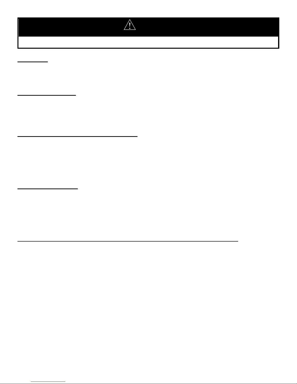
TYPICAL INSTALLATION ILLUSTRATION
If the building cold water supply has a back-flow preventer, check valve or water meter with check valve
provisions for thermal expansion of water in the hot water s
CAUTION
stem must be provided.
Figure 4. Typical Front Inlet Connection. Figure 5. Typical Front Inlet Connect with Storage Heater.
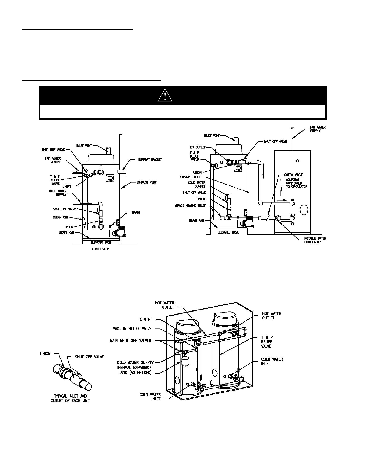
Figure 6. Typical Two Water Heater Connection.
14
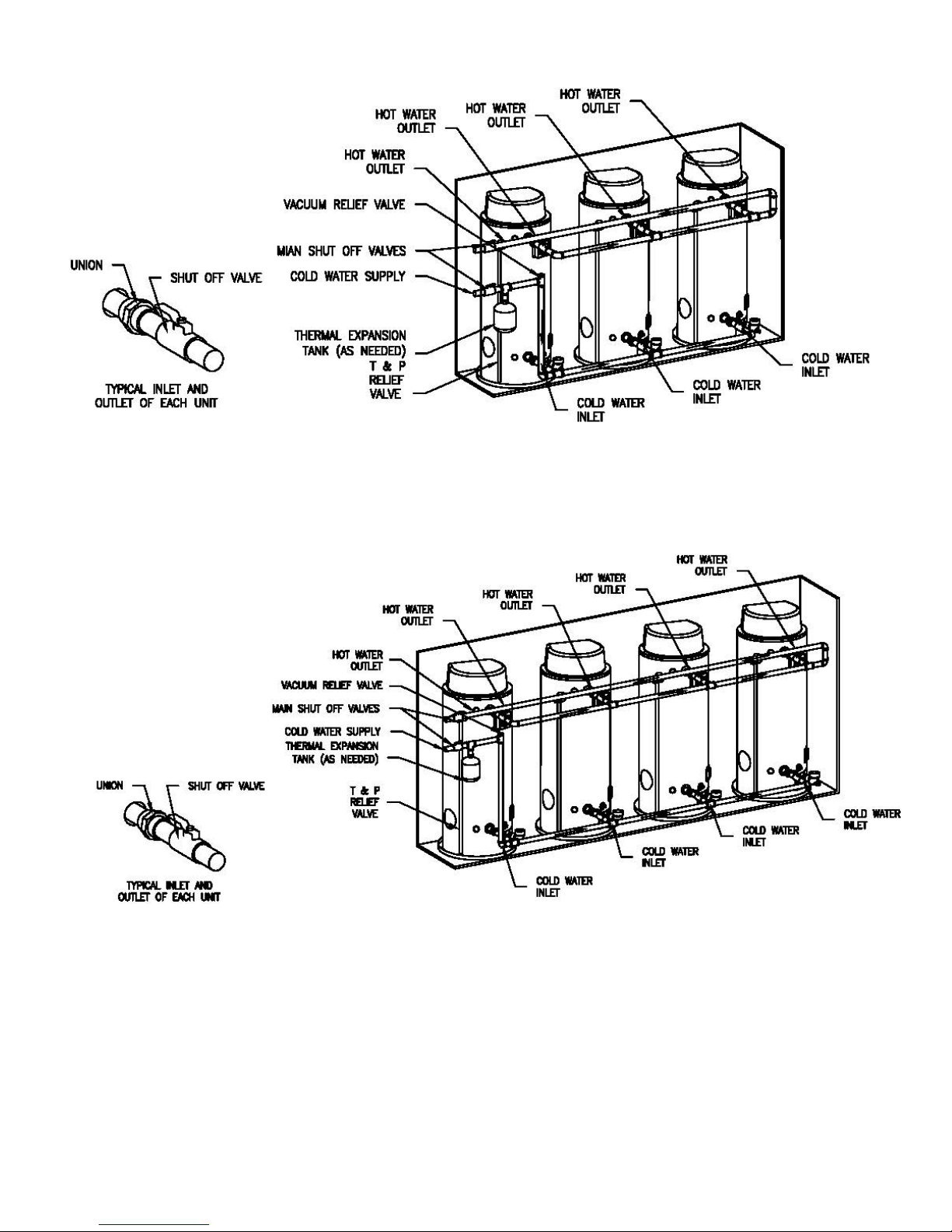
Figure 7. Typical Three Water Heater Connection.
Figure 8. Typical Four Water Heater Connection.
*This drawing shows a suggested piping configuration and other devices; check with local codes and
ordinances for additional requirements.
SECTION V: WATER CONNECTIONS
y
g
g
15
WARNING
Failure to install and maintain a new, listed temperature and pressure relief valve will release the manufacturer from
claim, which might result from excessive temperature and pressures.
an
Hydrogen gas can be produced in an operating water heater that has not had water drawn from the tank for a long
period of time (generally two weeks or more). HYDROGEN GAS IS EXTREMELY FLAMMABLE. To prevent the
possibility of injury under these conditions, we recommend the hot water faucet to be open for several minutes at the
kitchen sink before you use any electrical appliance, which is connected to the hot water system. If hydrogen is
present, there will be an unusual sound such as air escaping through the pipes as hot water begins to flow. Do not
smoke or have open flame near the faucet at the time it is open.
Keep clear of the combination temperature and pressure relief valve discharge line outlet. The discharge may be hot
h to cause scald injury. The water is under pressure and may splash.
enou
CAUTION
If sweat fittings are to be used, DO NOT apply heat to the nipples in front or side of the water heater. Sweat the tubing
to the adapter before fitting the adapter to the water connections. It is imperative that heat is not applied to the nipples
containin
INSTRUCTIONS FOR CONNECTIONS
a plastic liner.
1. BEFORE PROCEEDING WITH THE INSTALLATION, CLOSE THE MAIN WATER SUPPLY VALVE. After shutting
off the main water supply, open a faucet to relieve the water line pressure to prevent any water from leaking out of the
pipes while making the water connections to the water heater. The COLD water inlet and HOT water outlet are
identified on the water heater. Make the proper plumbing connections between the water heater and the plumbing
system to the house. Install a shut-off valve in the cold water supply line.
2. If this water heater is installed in a closed water supply system, such as the one having a back-flow preventer in the
cold water supply, provisions must be made to control thermal expansion. DO NOT operate this water heater in a
closed system without provisions for controlling thermal expansion. Warranties do not cover damages from thermal
expansion such as pressure bulges and/or deformities. Your water supplier or local plumbing inspector should be
contacted on how to control this situation.
3. After installation of the water lines, open the main water supply valve and fill the water heater. While the water heater
is filling, open several hot water faucets to allow air to escape from the water system. When a steady stream of water
flows through the faucets, close them and check all water connections for possible leaks.
4. Never operate the water heater without first being certain it is filled with water.
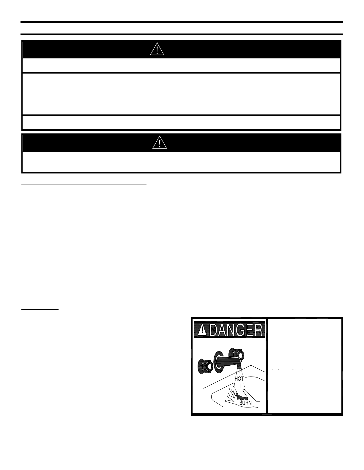
SCALDING
This water heater can deliver scalding temperature water
at any faucet in the system. Be careful whenever using
hot water to avoid scalding injury. Certain appliances such
as dishwashers and automatic clothes washers may
require increased temperature water. By setting the
thermostat on this water heater to obtain the increased
temperature water required by these appliances, you
might create the potential for scald injury. To protect
against injury, you should install an ASSE approved
mixing valve in the water system. This valve will reduce
point of discharge temperature by mixing cold and hot
water in branch supply lines. Such valves are available
from the local plumbing supplier. The following chart
details the relationship of water temperature and time with
regard to scald injury and may be used as a guide in
Water temperature over 125°F
(52°C) can cause severe burns
instantly or death from scalds.
Children, disabled and elderly
are at highest risk of being
scalded.
Review this instruction manual
before setting temperature
at water heater.
Feel water before bathing or
showering.
Temperature limiting valves are
available, contact local plumbing
supplier.
determining the safest water temperature for your
applications.
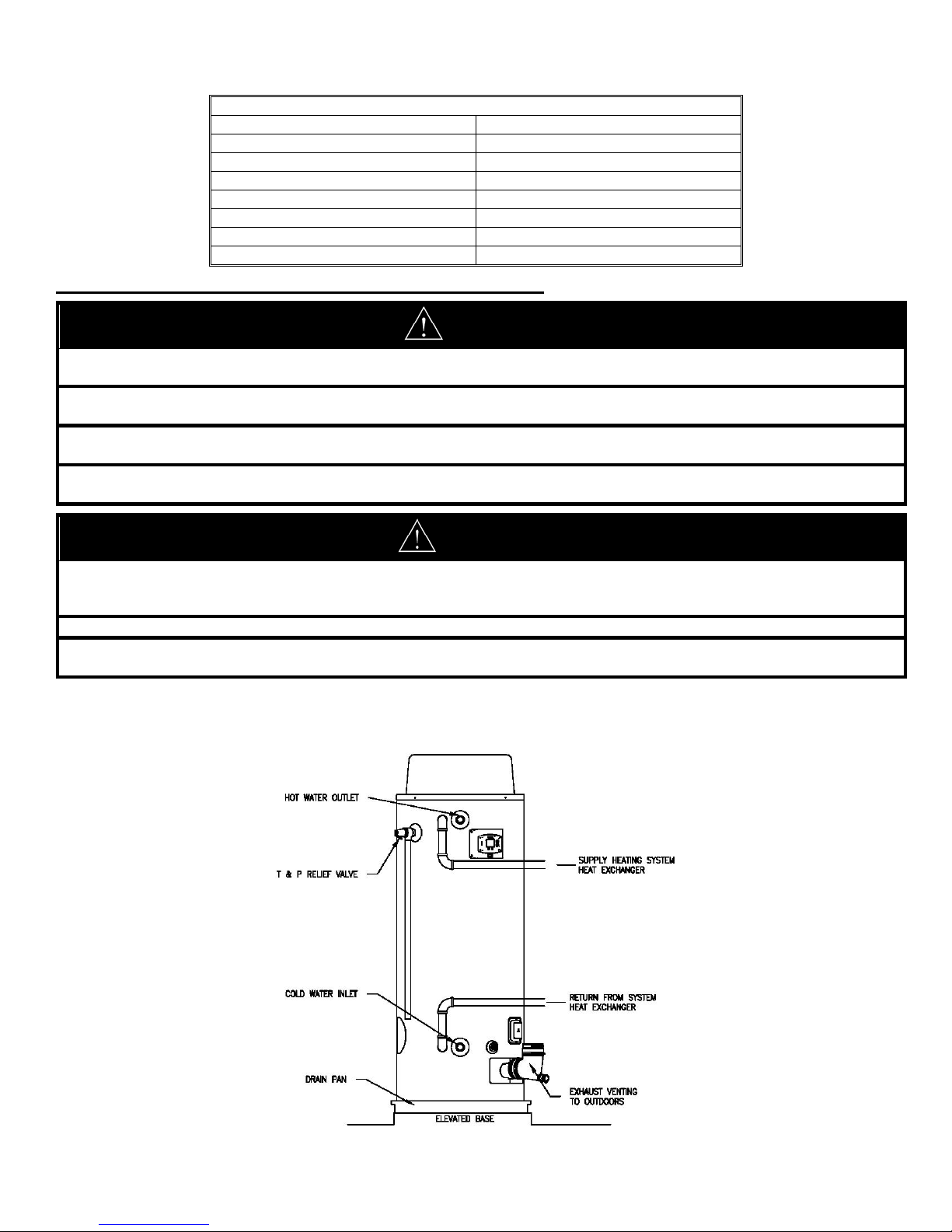
Table 2. Approximate Time/Temperature Scald Chart.
g
g
y
)
)
)
A
)
A
)
)
)
A
)
A
16
ALTERNATE SPACE HEATING WATER CONNECTIONS
APPROXIMATE TIME/TEMPERATURE RELATIONSHIPS IN SCALDS
120°F (49°C
125°F (52°C
130°F (54°C
135°F (57°C
140°F (60°C
145°F (63°C
150°F (66°C
155°F (68°C
More than 5 minutes
1½ to 2 minutes
bout 30 seconds
bout 10 seconds
Less than 5 seconds
Less than 3 seconds
bout 1½ seconds
bout 1 second
DANGER
Toxic chemicals, such as those used for boiler treatment, must not be introduced into potable water used for space
heatin
.
This water heater must not be connected to an existing heating system or component(s) previously used with a nonpotable water heatin
appliance.
All piping components connected to this water heater for space heating applications must be suitable for use with
potable water.
This water heater has combination water/space heating connections and is not intended to be used in space heating
applications.
onl
WARNING
When the system requires water for space heating at temperatures higher than required for other uses, a means such as
an ASSE approved mixing valve shall be installed to temper the water for those uses in order to reduce scald hazard
potential.
Failure to properly pipe this water heater may result in improper operation and damage to the water heater or structure.
Oxygen contamination of this water heater will cause corrosion of iron and steel components and can lead to water
heater failure.
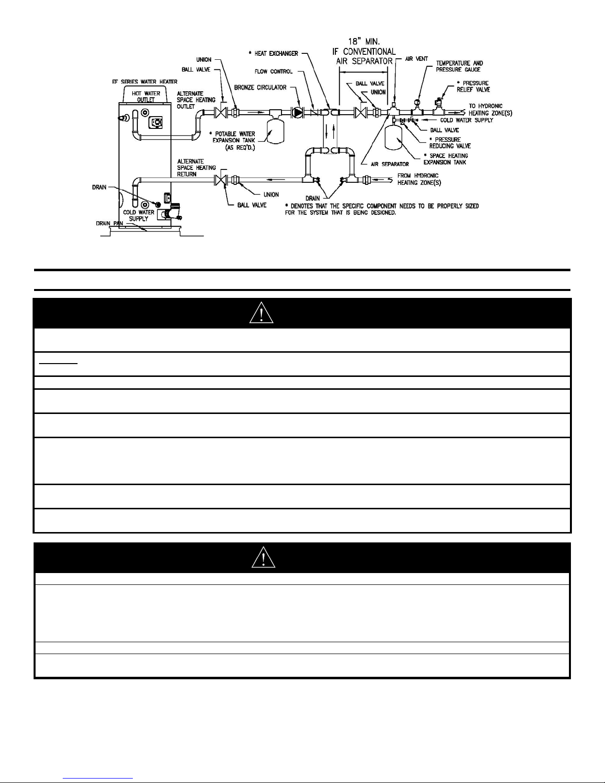
Connect the system supply and return piping to the water heater.
Refer to Figure 9 and Figure 10 for installation examples. Maintain a minimum 1/2” clearance from hot water piping to
combustible materials.
Figure 9. Alternate Space Heating Connections.
jury
y
Any
g
y
y
17
Figure 10. Typical Plumbing Schematic for Zoned Heating.
SECTION VI: VENTING
WARNING
The vent system must be properly installed. Failure to properly install the vent system could result in property damage,
personal in
DO NOT install damaged venting system components. If damage is evident then please contact the supplier where the
water heater was purchased, or the manufacturer listed on the rating plate for replacement parts.
Use only the vent terminals provided or factory authorized terminals for venting this water heater.
The water heater requires its own separate venting system. Do not connect the exhaust vent into an existing vent pipe
or chimne
All of the exhaust venting connections must be leak checked with a soap solution upon initial startup of the water heater.
leaks must be repaired before continuing operation of the water heater.
Do not terminate the venting where noise from the exhaust or intake will be objectionable. This includes locations close
to or across from windows and doors. Avoid anchoring the vent and intake pipes directly to framed walls, floors, or
ceilings unless rubber isolation pipe hangers are used. This prevents any vibrations from being transmitted into the
spaces.
livin
Do not exceed the venting distances or the number of elbows listed in this manual. Exceeding the maximum venting
distances ma
DO NOT operate this water heater until the venting installation is complete and the piping completed. Failure to
complete installation before operation can result in propert
, or death.
.
cause the water heater to malfunction or cause an unsafe condition.
damage, personal injury, or death.
Risk of carbon monoxide poisoning or fire due to joint separation or pipe breakage.
This water heater must be properly vented and connected to an approved vent system in good condition. DO NOT
operate water heater with the absence of an approved vent system. A clean and unobstructed vent system is
necessary to allow noxious fumes that could cause injury or loss of life to vent safely and will contribute toward
maintaining the water heater’s efficiency. The acceptance of the venting system is dependent upon full compliance with
these installation instructions.
Venting system must not pass through rated fire separations.
The venting system must be free to expand and contract. This venting system must be supported in accordance with
these instructions.
WARNING
NOTICE
)
g
g
18
For installations in Canada, field supplied vent piping must comply with CAN/CGA B149.1 (latest edition) and be
certified to the Standard For Type BH, Class II, 65°C, Gas Venting Systems, ULC S636. Components of this listed
system shall not be interchanged with other vent systems or unlisted pipe/fittings. All components and specified
primers and cements of the certified vent system must be from a single system manufacturer and not intermixed with
other system manufacturer’s vent system parts. The supplied vent connector and vent termination are certified under
ULC S636 and are also certified as part of the water heater. Refer to the following tables for approved venting
materials, primers, and cements. All approved primers and cements are to be used within their marked time
limitations.
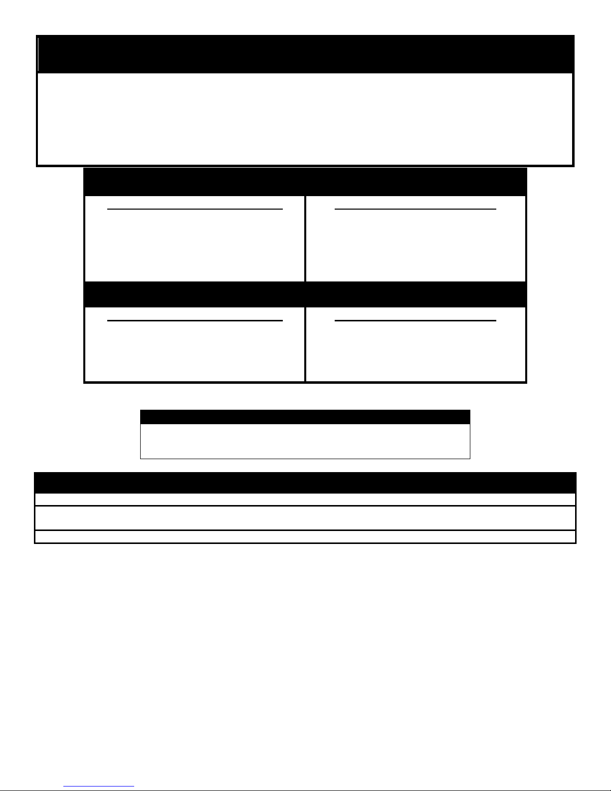
For installations in the US only
PVC DWV (ASTM D-2665)
PVC Sch. 40, 80, 120 (ASTM-D1785)
CPVC Sch. 40, 80 (ASTM-F441)
CPVC (ASTM D2846)
ABS Sch. 40 DWV (ASTM D2661)
For installations in the US only
PVC and CPVC Primer (ASTM-F656)
PVC Cement (ASTM D-2564)
CPVC Cement (ASTM F493)
ABS Primer and Cement (ASTM D-
2235
NOTICE
Use of cellular core PVC (ASTM F891), cellular core CPVC, or Radel
(polyphenosulfone) in non-metallic venting systems is prohibited and
coverin
non-metallic venting with thermal insulation is prohibited.
For installations in CANADA
ULC S636 approved PVC for flue gas
venting rated Class II, 65°C
ULC S636 approved CPVC for flue gas
venting rated Class II, 65°C
For installations in CANADA
ULC S636 approved Primer and
Cement for flue gas venting rated
Class II, 65°C
®
NOTICE
Before beginning installation of any vent pipe, read the vent pipe manufacturer’s installation instructions.
Do not install the water heater in any location where the ambient temperature may fall below freezing. Water heater
must be protected from freezin
Provide protection of the building materials from degradation by flue gases from the exhaust vent terminal.
This water heater has a certified category IV, per latest ANSI Z 21.10.3-2017.CSA 4.3-2017 revision. Refer to
the latest edition of the National Fuel Gas Code (ANSI Z223.1-latest edition), or in Canada, the Natural Gas and
Propane installation Code (B149.1-00 latest edition).
downdrafts during shutdown periods.
 Loading...