

Bradford White 100T399-SOLA Supplement To Installation & Operation Manual
100T399-SOLA SUPPLEMENT TO INSTALLATION & OPERATION
MANUAL INCLUDED WITH WATER HEATER
(SERIAL NUMBERS BEGINNING LK AND LATER)
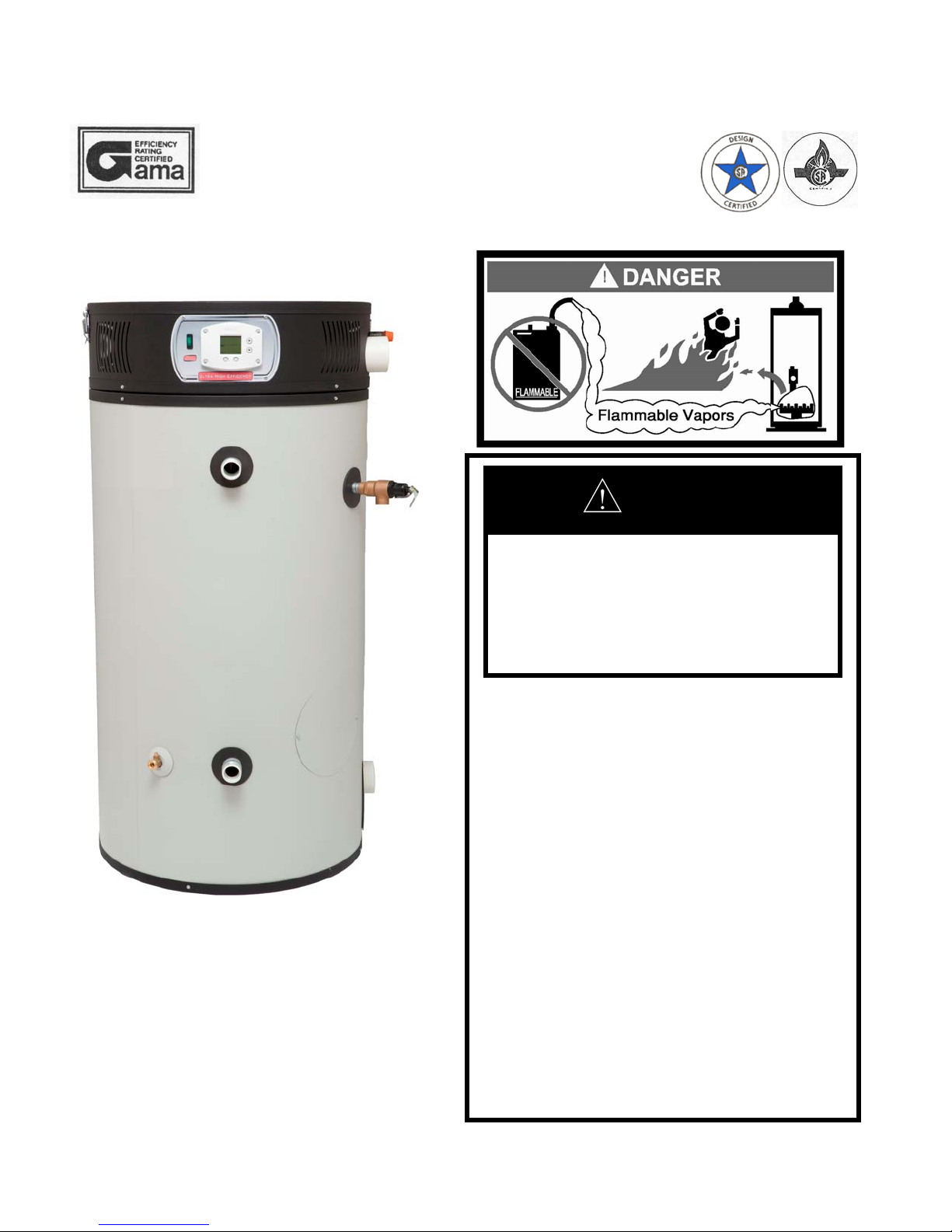
If the information in these
instructions is not followed exactly,
a fire or explosion may result
causing property damage, personal
injury or death.
- Do not store or use gasoline or other
flammable vapors and liquids in the
vicinity of this or any other appliance.
- WHAT TO DO IF YOU SMELL GAS
Do not try to light any appliance.
Do not touch any electrical switch;
do not use any phone in your
building.
Immediately call your gas supplier
from a neighbor’s phone. Follow
the gas supplier’s instructions.
If you cannot reach your gas
supplier, call the fire department.
- For your family’s comfort, safety and
convenience, it is recommended this
water heater be installed and
serviced by a plumbing professional.
WARNING
P/N 238-50688-00A 9/14

SECTION III: GENERAL INFORMATION
LOW FIRE START CONTROL FEATURES:
(In addition to pg. 6 of installation & operation manual.)
Honeywell R7910B1009 Control board controls ignition functions, combustion blower, gas valve, tank
temperature, and monitors safety functions in a single control.
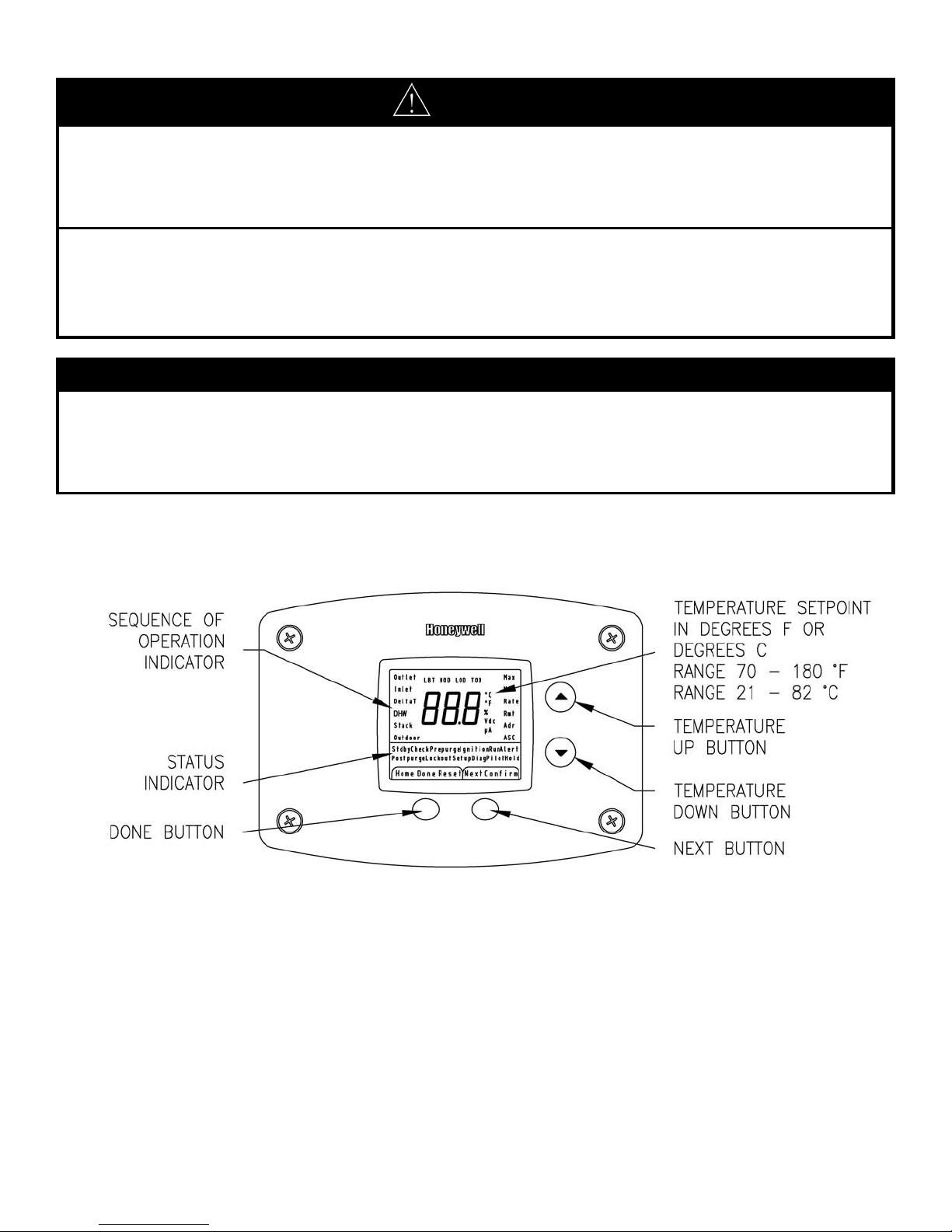
An attractive digital display on the top front of the water heater provides for setting and displaying the temperature
setpoint and monitoring the status of the water heater.
Durable direct spark ignition system.
The temperature adjustment range is 70˚F to 180˚F.
Combustion blower speed is reduced prior to ignition to light smoothly at a lower input rating.
Temperature setting may be viewed in either ˚F or ˚C
In Diagnostic Mode the tank temperature and flame sense current can be monitored for service.
Error codes will be displayed in the event the water heater needs service.
2
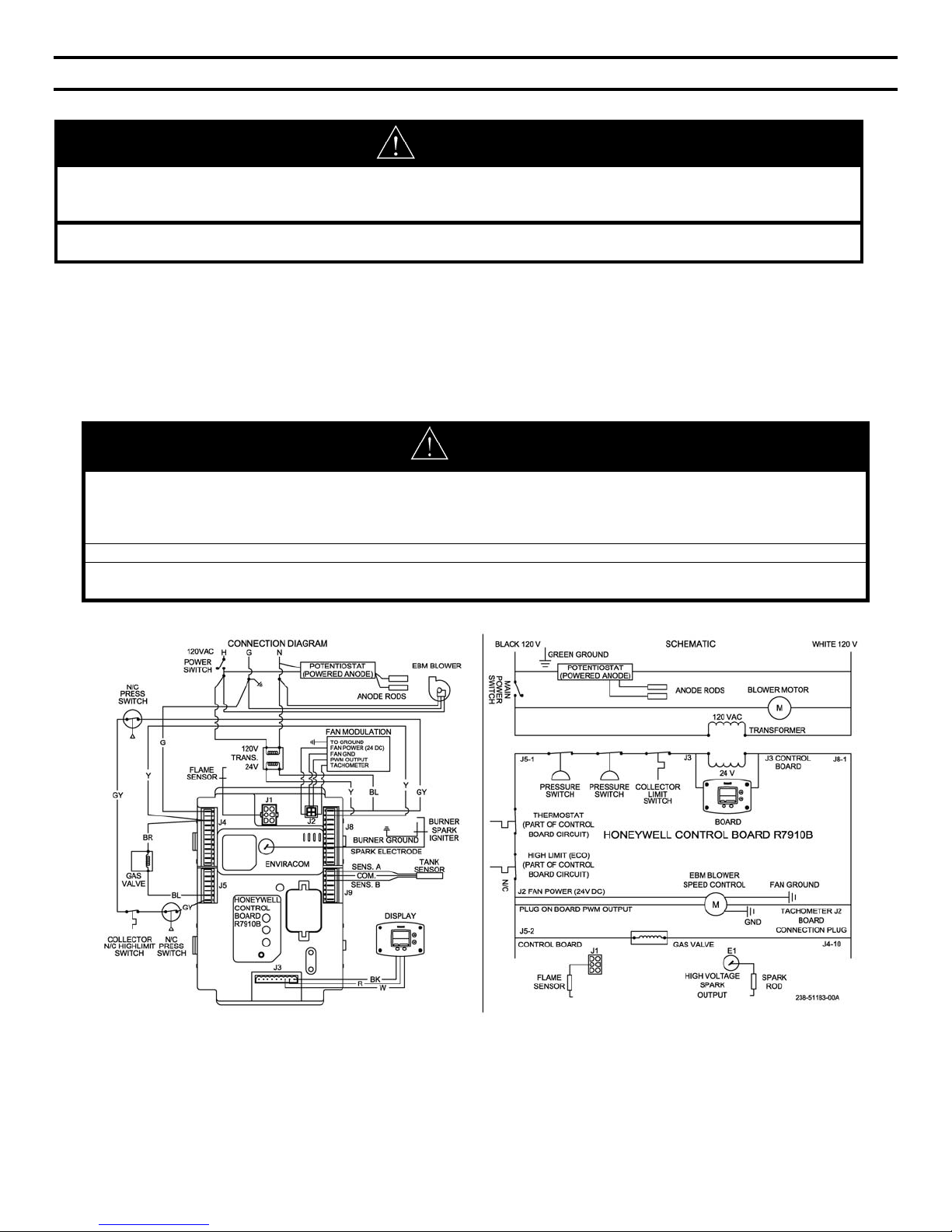
SECTION VIII: ELECTRICAL CONNECTIONS
(Replaces pg. 38 of installation & operation manual.)
WARNING
Turn off or disconnect the electrical power supply to the water heater before servicing. Label all wires prior to
disconnection when servicing controls. Wiring errors can cause improper and dangerous operation. Verify proper
operation after servicing.
All electrical wiring must be installed and grounded in accordance with local codes, or in the absence of local
codes, the National Electrical Code, ANSI/NFPA 70 and/or CSA C22.2 Electrical Code.
The water heater must be wired to a 120 VAC, 60 Hz, 15A power supply. The water heater must be wired on a separate
circuit and breaker. If a flexible line cord and plug is permitted by local code, then provide a three wire grounding type
receptacle within reach of the line cord provided on the control box. Do not plug the line cord into a receptacle that can
have the power supply interrupted by a switch that is used to control lights or another appliance.
If wiring in conduit is required, cut the line cord close to the control board and make the appropriate wiring conne ctions.
Install an electrical conduit connector on the outside jacket of the water heater. Refer to the wiring diagram for the correct
connections to each wire lead.
CAUTION
This water heater must be wired on a separate circuit. Failure to wire on a separate circuit may cause
improper operation or failure of the electrical components of the water heater. Refer to the “Electrical
Connections” section of the Installation and Operation Manual for complete instructions on electrical wiring and
connections to the water heater.
Do not energize the electric circuit before the water heater tank is filled with water.
This control is polarity sensitive. If the hot and neutral supply voltage is reversed, the control will not sense
flame and the water heater will not operate. Verify polarity before connecting the water heater.
Figure 25. Wiring Diagram and Schematic
3
SECTION IX: OPERATING INSTRUCTIONS
SEQUENCE OF OPERATION
(Replaces SEQUENCE OF OPERATION section on pg. 39 of installation & operation manual)
1. Thermostat calls for heat.
2. Blower ON.
3. Blower pre purge at reduced speed.
4. Spark rod sparks to the burner and gas valve opens – burner ignition.
5. Flame signal confirmed.
6. Blower remains at reduced speed for a short time to stabilize flame.
7. Blower increases to full speed for full input rate.
8. Thermostat satisfied.
9. Gas valve closes - Main burner OFF.
10. Blower post purge, then OFF.
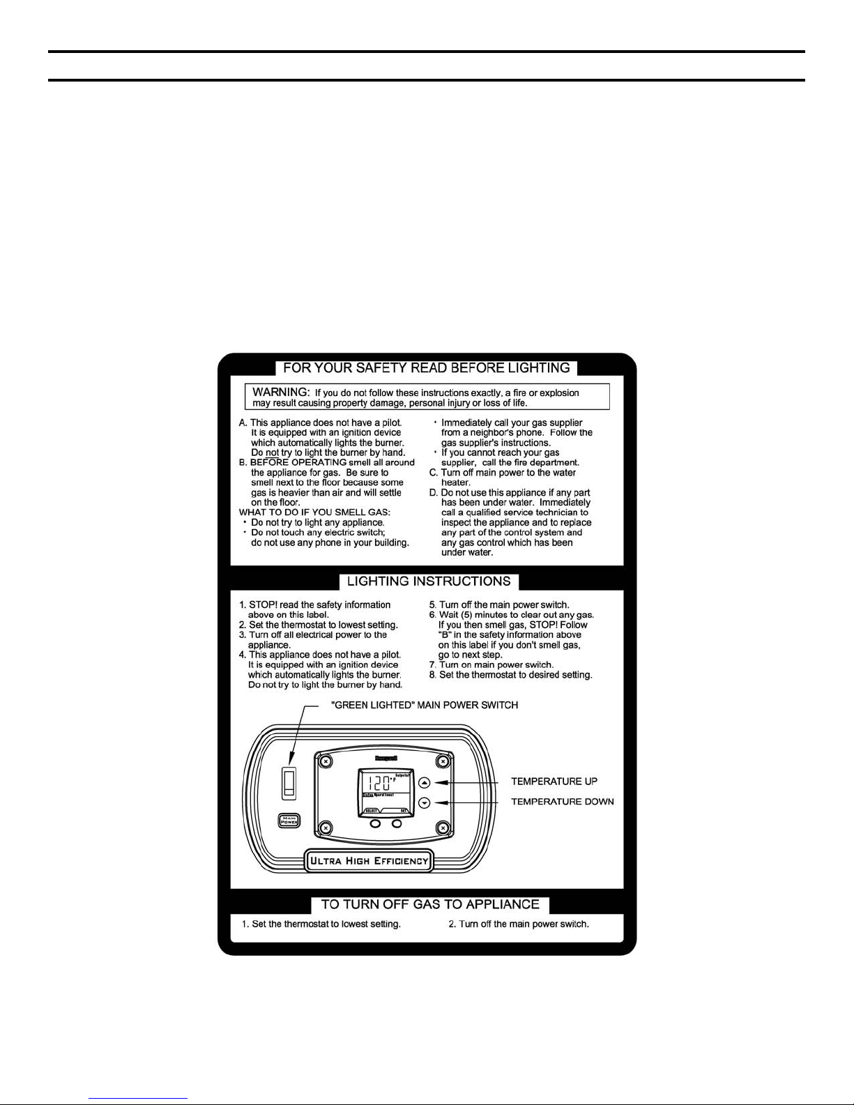
LIGHTING AND SHUT DOWN INSTRUCTIONS
(Replaces pg. 40-46 of installation & operation manual.)
Figure 26. Lighting Instruction Label.
4
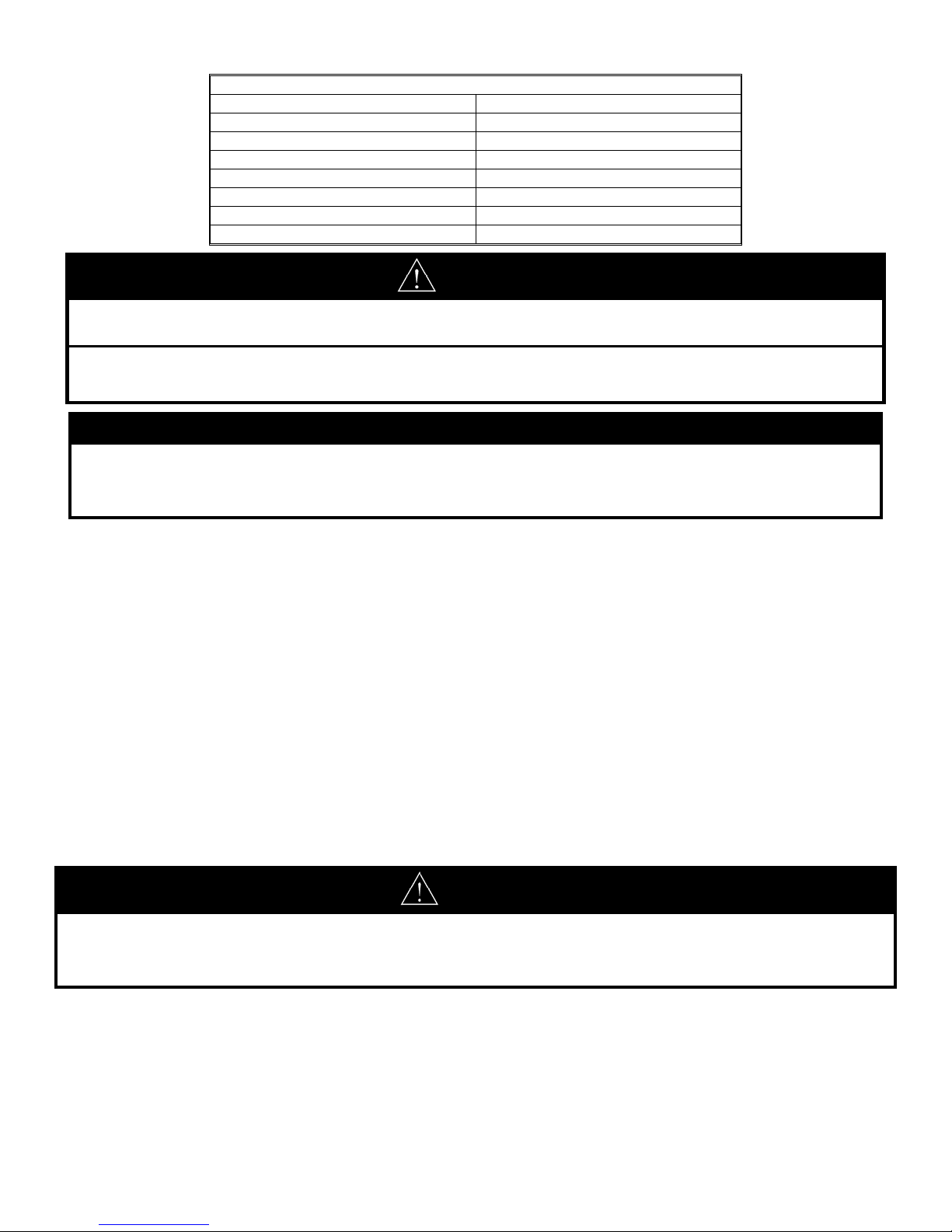
TEMPERATURE ADJUSTMENT
APPROXIMATE TIME/TEMPERATURE RELATIONSHIPS IN SCALDS
120°F (49°C) More than 5 minutes
125°F (52°C) 1½ to 2 minutes
130°F (54°C) About 30 seconds
135°F (57°C) About 10 seconds
140°F (60°C) Less than 5 seconds
145°F (63°C) Less than 3 seconds
150°F (66°C) About 1½ seconds
155°F (68°C) About 1 second
CAUTION
This water heater, when set at a lower temperature setting is not capable of producing hot water of sufficien t
temperature for sanitizing purposes.
This water heater is equipped with an energy cut out device to prevent overheating. Should overheating occur or
the gas supply fails to shut off, turn off the control panel power switch to the appliance and call a qualified service
agency.
NOTICE
The lower the temperature setting, the greater the energy efficiency, both to heat the water and to maintain the
storage temperature during standby periods. Lower water temperatures also extend tank life. Remember, no
water heating system will provide exact temperatures at all times. Allow a few days of operation at this setting to
determine the correct temperature setting consistent with the requirements for the installation.
The water heater temperature setting is adjusted by using the control display mounted to the control surround jacket of the
water heater. The water heater thermostat is set at the lowest setpoint of 70F (21
The control display shows the temperature setpoint in degrees Fahrenheit (
the water heater (“Standby” or “Run”).
For energy efficient operation of your water heater, the suggested initial temperature setting is 120F (49C). During the
winter season, or any cold period, you may desire a higher temperature setting to adjust for the colder incoming water.
This adjustment, however, may cause additional condensation to form on the cooler tank surface. This does not mean
the tank is leaking. During summer months, the warmer incoming water temperatures will benefit the performance of your
water heater and reduce the amount of condensation developed.
Condensation does not mean your tank is leaking. Most of reported tank leaks on installation are proven to be
condensation. To avoid unnecessary inconvenience and expense, make sure the tank is leaking before calling an
independent servicing contractor or qualified service professional.
If the water heater is to remain idle for 30 days or more or is subjected to freezing temperatures while shut off, the water
heater and piping should be fully drained and the drain valve should be left fully open. Refer to the “General Operation”
section of this Installation and Operation Manual for the procedure on draining the water heater.
C) when shipped from the factory.
F) or degrees Celsius (C), and the status of
Hotter water increases the risk of scald injury. Scalding may occur within 5 seconds at a temperature setting of 140°F
(60°C). To protect against hot water injury, install an ASSE approved mixing valve in the water system. This valve will
reduce point of discharge temperature by mixing cold and hot water in branch water lines. A licensed plumbing
professional or local plumbing authority should be consulted.
DANGER
5
WARNING
If the water heater display does not show “Standby” or “Run”, there may be an operating malfunction with the water
heater. If this is the case, a numeric code will be displayed. Refer to the label next to the display for the definition of
the error code and call your plumbing professional or service agent to service the water heater. Do not try to reset the
water heater without having a qualified service person to diagnose and correct the problem. If the display is blank or
does not show an error code, make sure there is power to the water heater.
Setting the water temperature to the maximum setpoint can result in scalding hot water delivered to the faucets. It is
highly recommended that the setpoint be adjusted to the lowest temperature possible for the needs of the installation.
Make sure the water heater control display is not in a public area that can result in the temperature settings being
improperly adjusted. See previous warning on scalds and an ASSE approved mixing valve.
NOTICE
If the water heater display does not show “Standby” or “Run”, there may be an operating malfunction with the water
heater. If this is the case, a numeric code will be displayed. Refer to the label next to the display for the definition of
the error code and call your plumbing professional or service agent to service the water heater. Do not try to reset the
water heater without having a qualified service person to diagnose and correct the problem. If the display is blank or
does not show an error code, make sure there is power to the water heater.
6
 Loading...