

BRADEN PD12C, PD15B, PD10-75B, PD10-77B, PD15-75B Material List And Installation Instructions
...
MATERIAL LIST
AND
INSTALLATION INSTRUCTIONS
RATCHET AND PA WL
BRADEN
www.paccarwinch.com
For Use With The Following Braden Hoists:
PD12C
PD15B
PD10-75B PD10-77B
PD15-75B PD15-77B
LIT2137 R3
July 2017
Printed in USA
PACR
800 E. Dallas Street, Broken Arrow, OK 74012
PHONE (918) 251-8511 FAX (918) 259-1575
WINCH
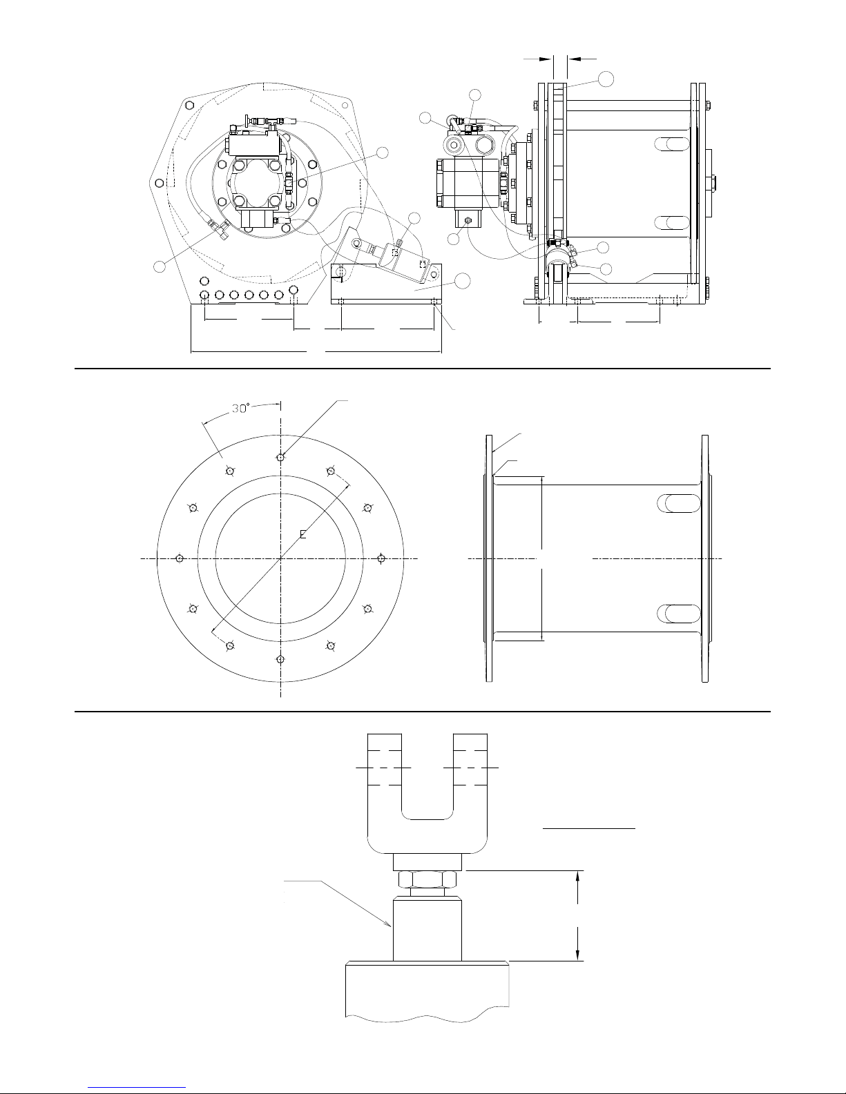
FIG 1
FIG 2
FIG 3
1.31 in. (33.3 mm)
CLEVIS
ADJUSTMENT
NO PAINT ON
THIS SURFACE
D ± .06
Min. Mat’l Removal
for 80% Cleanup
.06 R
.422 (+.008, -.003) thru
1/2 -13UNC-2B
12 holes
1.38
99
N
K
P
H
G
L
86
J
M
8.88
B
C
9.25
.531
4 HOLES
3.88
A
Disclaimer: Due to the added
wrench flat feature on the pawl shaft,
1.31 inches is no longer feasible.
Tighten jam nut to contact followed
by the clevis. (End measurement will
be 1.38 inches.)

INSTALLATION INSTRUCTIONS FOR ASSEMBLY
OF RATCHET AND PAWL KITS ON BRADEN “PD”
HOISTS
1. Remove wire rope from the hoist (if applicable) and
move hoist to a clean work area for disassembly.
2. Disassemble hoist per instructions given in
PD12C/PD15B Service Manual (publication # PB-
115)
3. Machine and drill holes on the inside of the drum
flange opposite the cable wedge pocket (see Figure
2)
4. Tap drilled holes to ½-13UNC-2B (see Figure 2)
5. Align the ratchet wheel halves (item 99) with the
twelve (12) tapped holes in the cable drum making
the O.D. of the ratchet halves concentric with the
O.D. of the drum flange. The O.D. of the ratchet
halves should be almost flush with the outside of the
drum flange. Alimited amount of drum flange runout may be possible with variances in the drum
castings
6. Attach the ratchet wheel halves to the drum flange
using twelve (12) ½” UNC x 1½” grade 8, zinc plated capscrews (104322) along with ½” standard lock
washers (11026). Torque capscrews to 80 ft. lbs.
7. Position pawl assembly (item 86) in place per
dimensions A, B & C. Slowly rotate the cable drum
so that the pawl fully engages the ratchet wheel
(see Figure 1). Adjust the clevis on the 81663 cylinder assembly to 1.31 in. (33.3 mm) (see Figure 3).
8. Connect all hoses.
9. Attach the pawl assembly base to the crane mounting structure using four (4) ½” Grade 8, zinc plated
capscrews to prevent corrosion. The capscrew
length will depend on the mounting structure.
Torque the capscrews to the proper torque specification.
10. Check operation of hoist and ratchet & pawl assembly to insure that the pawl will always fully disengage ratchet wheel (when control lever is in lowering mode) and that the pawl engages fully (when
control lever is in neutral or the raise position).
TROUBLESHOOTING
T
HE PAWL WILL NOT ENGAGE OR NOT ENGAGE FULLY:
1. Check Figure 3 and adjust if necessary; should be
1.31 in. (33.3 mm).
2. The spring in the 81663 cylinder assembly may be
weak or broken. Disassemble the cylinder and
inspect spring. If it is not broken, check spring free
height. It should be 2.50 ± .09 in. (63.5 ± 2.3 mm).
3. Check the orifice (located in the piston) to be certain
it is clear. The orifice hole is approximately .020 in.
(.51 mm) in diameter.
T
HE PAWL WILL NOT DISENGAGE:
1. If the ratchet is too tight against the pawl it may not
disengage. Raise the load slightly and disengage
normally.
2. Check Figure 3 and adjust if necessary.
C
YLINDER ASSEMBLY LEAKS HYDRAULIC FLUID:
1. Disassemble, remove and replace all O-rings.
A
DJUSTMENT
Note: The 81663 cylinder has an internal relief
valve that is factory pre-set (1200 to 1500 psi). No
further adjustment is necessary.
Pawl Assembly
Winch
A
(in.)B (in.)C (in.)D (in.)
E
(in.)
Part No. Part No. Qty. Part No. Qty.
Part No. Qty.
PD12C-02 8.27 3.13 23.64 10.88 13.38 62386 29696 2 104322 12 11026 12
PD12C-04 8.17 4.73 24.98 11.75 15.38 62387 29700 2 104322 12 11026 12
PD12C-05 8.27 3.13 23.64 11.00 13.38 62386 29702 2 104322 12 11026 12
PD15B-04 8.16 4.73 24.98 11.75 15.38 62387 29700 2 104322 12 11026 12
PD15B-05 8.27 3.13 23.64 11.00 13.38 62386 29702 2 104322 12 11026 12
Lockwashers
Capscrews
Ratchet Half
PD10-75B 12.14
PD15-75B 12.14 8.62 30.25 11.00 13.38 65256 29702 2 104322 12 11026 12
PD10-77B 8.75 3.875 30.25 11.00 13.38 65256 29702 2 104322 12 11026 12
PD15-77B 8.75 3.875 30.25 11.00 13.38 65256 29702 2 104322 12 11026 12
8.62 30.25 11.00 13.38 65256 29702 2 104322 12 11026 12

HYDRAULIC SCHEMATIC
(FITTINGS SHOWN MAY NOT MATCH ALL HOISTS)
RATCHET AND PAWL CYLINDER
PART NUMBER 81663
NOTE:
CONNECT PORT (H) ON CYLINDER TO PORT (G) ON
MOTOR (LOWERING).
C
ONNECT PORT (J) ON CYLINDER TO PORT (L) ON
HOIST AND PORT (K) ON BRAKE VALVE.
CONNECT PORT (M) ON CYLINDER TO PORT (P) ON
MOTOR AND PORT (N) ON BRAKE VALVE.
NOTE:
SEAL KIT FOR CYLINDER 81663 IS PART NUMBER 61614.
LIT2137 R3
July 2017
Printed in USA
 Loading...