


OPERATOR’S AND PARTS
MANUAL
BC60, BC72 & BC78
ROTARY CUTTERS
UNIVERSAL
SKID STEER
APPLICATIONS
SERIAL NUMBER: ___________________ Manual Number: OM636
Part Number: 75536
MODEL NUMBER: ___________________ Rev. 7
800-456-7100 I www.paladinlcg.com 503 Gay Street, Delhi, IA 52223, United States of America
8904 6-25-10-8

READ ENTIRE OPERATOR'S & PARTS MANUAL BEFORE OPERATING!
DANGER! ROTATING BLADE HAZARD! STAY BACK!
OBJECTS CAN BE THROWN!
DO NOT operate near bystanders.
DO NOT place hands or feet under deck while in operation or with engine
running.
DO NOT operate without a shatterproof door (or front shield) installed on
loader.
WARNING! Before leaving the operator's seat: Lower the lift arms against frame and
place unit on the ground. Disengage auxiliary hydraulics. Stop Engine.
Engage parking brake. Remove the key.
WARNING! Operatingthestandardowrotarycutteronahighowhydraulicsystem
may cause severe injury or death to the operator or bystanders due to the
increasedRPM.DoNOToperatethestandardowrotarycuttersonhighow
hydraulic systems.
WARNING! Lift limiting chain must be properly installed before operation.
WARNING! AVOID STALLING ROTARY CUTTER. During operation, continuous blade
rotation is required to prevent overheating of the hydraulic system. To
monitor the blade rotation, there is a window in the motor cover shield so
the operator can monitor the blade rotation indicator disk. This disk should
always be rotating during operation to prevent overheating of the hydraulic
system.
SERVICE
When servicing your rotary cutter, remember to use only manufacturer replacement
parts. Substitute parts may not meet the standards required for safe, dependable operation.
To facilitate parts ordering, record the model and serial number of your unit on the
cover or in the space provided on this page. This information may be obtained from the iden-
tication plate located on the right front of the mounting plate.
MODEL____________________________________
SERIAL NUMBER___________________________
DATE PURCHASED_________________________
The parts department needs this information to ensure that you receive the correct
parts for your specic model.
9115 10-11-06-3

TABLE OF CONTENTS
TO THE OWNER ...............................................................................................A
SAFETY PRECAUTIONS ................................................................................ B
General Information
To The Operator
Before You Start
Working With The Rotary Cutter
Transporting the Rotary Cutter
Maintenance
INTERNATIONAL SYMBOLS .......................................................................... C
PREOPERATION ............................................................................................. D
General Information
Before Operation
Skid-Steer
Major Component Nomenclature
ROTARY CUTTER ASSEMBLIES ....................................................................E
60" & 72" Standard Flow Cutter Assemblies
72" & 78" High Flow Cutter Assemblies
High Flow Drive Assembly
High Flow Hydraulic Assemblies
Wheel Kit Assembly
INSTALLATION INSTRUCTIONS ....................................................................F
OPERATING INSTRUCTIONS ........................................................................ G
General Information
Operating Tips
Operation
Troubleshooting Operating Conditions
LUBRICATION ................................................................................................. H
MAINTENANCE ................................................................................................ L
Daily
Every 40 Hours Operation
Replacing Blades
Replacing Hydraulic Motor
Replacing Gearbox/Motor Coupler
Replacing Gearbox
STORAGE ........................................................................................................ M
TROUBLESHOOTING ..................................................................................... N
BOLT TORQUE ............................................................................................... O
SPECIFICATIONS .............................................................................................P
DECALS ........................................................................................................... Q
PREDELIVERY CHECK LIST .......................................................................... R
LIMITED WARRANTY ......................................................................................S
9026 10-11-06-4

THIS PAGE
IS INTENTIONALLY
BLANK

A
A
TO THE OWNER
GENERAL COMMENTS
Congratulations on the purchase of your new rotary cutter! Your cutter was
carefully designed and manufactured to give you years of dependable service. Your
cutter will require some minor maintenance (such as cleaning) to keep it in top
working condition. Be sure to observe all safety precautions and maintenance
procedures as described in this manual.
ABOUT THIS MANUAL
This manual has been designed to help you do a better, safer job. Read this
manual carefully and become familiar with it's contents. Remember, never let
anyone operate this unit without reading the "Safety Precautions" and
"Operating Instructions" sections of this manual. (See Sections B and G
respectively.)
Unless noted otherwise, right and left sides are determined from the position
of the skid-steer operator sitting in the seat facing forward.
SAFETY ALERT SYMBOL
This is the "Safety Alert Symbol" used by this industry. This symbol is
used to warn of possible injury. Be sure to read all warnings carefully.
They are included for your safety and for the safety of others working
with you.
SERVICE
When servicing your rotary cutter, remember to use only manufacturer
replacement parts. Substitute parts may not meet the standards required for safe,
dependable operation.
To facilitate parts ordering, record the model and serial number of your unit in
the space provided on this page. This information may be obtained from the identification plate located on the right front of the mounting plate.
MODEL____________________________________
SERIAL NUMBER___________________________
DATE PURCHASED_________________________
The parts department needs this information to insure that you receive the
correct parts for your specific model.
8908
11-2-04-2

THIS PAGE
IS INTENTIONALLY
BLANK

BB
SAFETY PRECAUTIONS
TAKE NOTE! THIS SAFETY ALERT SYMBOL FOUND THROUGHOUT THIS
MANUAL IS USED TO CALL YOUR ATTENTION TO INSTRUCTIONS INVOLVING YOUR PERSONAL SAFETY OR OTHERS. FAILURE TO FOLLOW
THESE INSTRUCTIONS CAN RESULT IN INJURY OR DEATH.
THIS SYMBOL MEANS:
ATTENTION!
BECOME ALERT!
YOUR SAFETY IS INVOLVED!
SIGNAL WORDS: Note the use of signal words DANGER, WARNING, and
CAUTION with the safety messages. The appropriate signal word for each has
been selected using the following guidelines:
DANGER: Indicates an imminently hazardous situation, which if not avoided,
will result in death or serious injury. This signal word is to be limited
to the most extreme situations, typically for machine compo-
nents which, for functional purposes, cannot be guarded.
WARNING: Indicates a potentially hazardous situation, which if not avoided,
could result in death or serious injury, and includes hazards that
are exposed when guards are removed. It may also be used to
alert against unsafe practices.
CAUTION: Indicates a potentially hazardous situation, which if not avoided,
may result in minor or moderate injury. It may also be used to
alert against unsafe practices.
6621
5-18-95

B
B
SAFETY PRECAUTIONS
ROTARY CUTTER
GENERAL INFORMATION
This section is composed of various warnings and safety tips. Read and learn
all the information in this section before you attempt to use your rotary cutter.
Also read your vehicle owner's manual before using your equipment. This knowledge
will help you operate your unit safely. Do not take this information lightly, it is pre-
sented for your benet and for the benet of others working around you.
The "Safety Alert Symbol" (as described in Section A and at the beginning of
Section B) will be used throughout this manual. It will appear with the word DANGER,
WARNING, or CAUTION above it, and a safety message pertaining to the specic topic
being covered. Take the time to read these messages as you come across them.
TO THE OPERATOR
The primary responsibility for safety with the equipment falls to the operator.
Make sure that the equipment is operated only by responsible & competent individuals
with the proper instruction. It is the skill, care, common sense, and good judgment of
the operator that will determine how efciently and safely the job is performed. Know
your equipment before you start. Know its capabilities, dimensions, and how to oper-
ate all the controls. Visually inspect your equipment before you start, and never operate
equipment that is not in proper working order.
BEFORE YOU START
1. Read the entire loader and rotary cutter operator's manuals before ever attempting to use the loader. This knowledge is necessary for safe operation.
2. Do NOT operate the standard ow rotary cutter on high ow hydraulic sys-
tems. Severe injury or death could occur due to the increased RPM.
3. Do not operate without a shatterproof (demolition) cab door or front shield
on loader.
4. Always wear safety goggles and hearing protection during operation, and
make sure ALL safety shields and chains are properly installed.
5. Follow all safety decals. Keep them clean and replace them if they become
worn, damaged, or illegible.
6. Do not paint over, remove, or deface any safety signs or warning decals on
your equipment.
7. Know your equipment inside and out. Know how to operate all controls and
know emergency shut down procedures.
8. Keep all stepping surfaces, pedals, and controls free from dirt, grease and
oil. Keep equipment clean to help avoid injury from a fall when getting on or off
equipment.
8909 10-11-06-4

B
B
SAFETY PRECAUTIONS
ROTARY CUTTER
9.
10.
11.
12.
13.
14. Never leave the unit unattended when in a raised position. Always make
15. Test all controls before you begin.
Use handholds and step plates when getting on/off . Failure to do so
could cause a fall.
Never operate the unit near bystanders, traffic, pets, livestock, or buildings. Be sure others know when and where you will be working. Make sure no
one is behind equipment or for several hyndred feet in any direction around the
cutter when in operation. Never allow anyone to approach the cutter when in
operation.
Never take passengers on your equipment. There is no safe place for a
passenger.
Never try to board equipment while it is running.
Turn off engine, remove the key and disconnect hydraulic couplers
before performing maintenance. If unit must be left raised for maintenance
or any other reason, block the unit securely to prevent accidental release of the
lifting mechanism. Serious damage or personal injury could result.
sure both skids are on the ground, and keys removed before leaving the unit
unattended.
16. Do not smoke when refueling. Allow room in the gas tank for expansion.
Wipe up any spilled fuel. Secure cap tightly when done.
WORKING WITH THE ROTARY CUTTER
1. Never operate the unit without first reading and understanding the
operator's manual.
2. Never operate the rotary cutter without the lift limiting chain(s) properly
installed. Refer to Section F.
3. Operate the unit only in daylight, or sufficient artificial light.
4. Do not carry load with arms in the raised position. Always carry loads as
close as possible to the ground.
5. Check your work area, and know where all utility lines are. Avoid hitting
underground electrical wires, cables, pipes, fence posts, gas lines, uneven
sidewalk edges, large rocks, etc.
6. Never operate equipment while under the influence of alcohol, prescription drugs, nonprescription drugs, or illegal drugs which could inhibit physical
and/or mental capacity.
7. Do not exceed rated operating capacity, as machine may become
unstable which may result in loss of control.
8. Do not operate the unit without covers and chains installed.
8910
11-2-04-3

B
B
SAFETY PRECAUTIONS
ROTARY CUTTER
9. Do not place hands or feet under deck while in operation or with engine
running.
10.
11. ALWAYS LOWER THE LOADER ARMS TO THE GROUND, SHUT OFF THE
TRANSPORTING THE ROTARY CUTTER
1.
2.
MAINTENANCE
1. Never work on equipment while it is running. Always lower the loader arms
2. Never make hydraulic repairs while the system is under pressure. Injury or
3. Observe proper maintenance schedules and repairs to keep the unit in safe
Do not raise the deck when blades are rotating.
ENGINE AND REMOVE THE KEY BEFORE GETTING OFF THE UNIT.
Follow all federal, state and local regulations when transporting the unit on
public roads.
Use extra care when loading or unloading the machine onto a truck or trailer.
Disconnect hydraulic couplers during transportation.
to the ground, shut off the engine, remove the key, and disconnect hydraulic
couplers before performing maintenance on the unit.
death could result.
working order.
4 Always wear safety goggles or glasses when working on equipment.
5. Use only manufacturer recommended replacement parts. Other parts may be
substandard in fit and quality.
WARNING! Escaping fluid under pressure can have sufficient force to penetrate
the skin causing serious personal injury. Fluid escaping from a very
small hole can be almost invisible. Use a piece of cardboard or wood,
rather that hands to search for suspected leaks.
Keep unprotected body parts,
such as face, eyes, and arms as
far away as possible from a
suspected leak. Flesh injected
with hydraulic fluid may develop
gangrene or other permanent
disabilities.
If injured by injected fluid, see a
doctor at once. If your doctor is
not familiar with this type of
injury, ask him to research it
immediately to determine proper
treatment.
HYDRAULIC HOSE
CARDBOARD
MAGNIFYING GLASS
OR FITTING
8911
11-2-04-3

CC
INTERNATIONAL SYMBOLS
As a guide to the operation of your equipment, various international
symbols have been utilized on the instruments and controls. The symbols
are shown below with an indication of their meaning.
Engine speed Alternator charge
Hours recorded Power take-off (on)
Engine water temperature Power take-off (off)
Lights "Tortoise," slow or minimum setting
Horn "Hare," fast or maximum setting
Engine oil pressure Caution
Hazard warning Control lever operating direction
Axle connect Rock shaft (raised)
Axle disconnect Rock shaft (lowered)
Continuously variable Remote cylinder (extended)
Increase Remote cylinder (retracted)
Decrease Remote cylinder (FLOAT)
Diesel fuel Differential lock
Creeper range Read operators manual
High range Neutral
Low range Forward
Reverse
3869
4-14-94-2

D
D
PREOPERATION
ROTARY CUTTER
GENERAL INFORMATION
The BRADCO Rotary Cutters were designed to be easy to use and maintain. They are operated by the skid-steer auxiliary hydraulics. The cutters mount to
the toolbar / quick attach mechanism for easy mounting.
Unless noted otherwise, right and left are determined from the position of the
skid-steer operator sitting in the operator's seat facing forward.
Remember to read the "Safety Precautions" and "Operating Instructions"
sections of the manual BEFORE you attempt to install or use the rotary cutter.
NOTE: The illustrations and data used in this manual were current (according
to the information available to us) at the time of printing, however, we reserve
the right to redesign and change the rotary cutters as may be necessary with-
BEFORE OPERATION
The primary responsibility for safety with this equipment falls to the opera-
tor. Make sure that the equipment is operated only by trained individuals that have
read and understand this manual. Don't hurry the learning process or take the unit
for granted. Practice the operation of your new equipment and become familiar with
the controls and the way it handles on your machine.
If there is any portion of this manual or function you do not understand, contact your local authorized dealer or the manufacturer.
DANGER! TO AVOID SERIOUS PERSONAL INJURY OR DEATH THE BRAD-
CO ROTARY CUTTER MUST NOT BE ATTACHED TO ANY POWER
UNIT THAT DOES NOT HAVE A SHATTERPROOF DOOR (OR
WARNING! OPERATING THE STANDARD FLOW ROTARY CUTTER ON A
HIGH FLOW HYDRAULIC SYSTEM MAY CAUSE SEVERE INJURY
OR DEATH TO THE OPERATOR OR BYSTANDERS DUE TO THE
SKID-STEER
BRADCOhasdesignedbothstandardowandhighowrotarycutters.The
standardow rotarycuttersareNOTdesignedforuseonhighowskid-steers.Operatingthestandardowonahighowsystemwillvoidtherotarycutterwarranty.
For maximum operation, see the recommended GPM for the rotary cutter you have
received.
Your skid-steer must have an auxiliary hydraulic system and a shatterproof
door or front shield to run the rotary cutter.
StandardSAEatfacehydraulicquickcouplersaresuppliedwithyourrotary
cutter. If you require an alternate set of couplers, you will need to purchase these
fromyourdealer.Thesecouplersmustta#12MBoendandconnecttoyourskid-
steer auxiliary hydraulic system.
9008 10-11-06-3

D
D
PREOPERATION
ROTARY CUTTER
NOMENCLATURE
Throughout this manual, reference is made to various rotary cutter components. The purpose of this page is to acquaint you with the various names of
these components. This knowledge will be helpful when reading through this
manual or when ordering service parts.
MOTOR COVER SHIELD
LIFT LIMITING CHAIN
QUICK ATTACH
DISCHARGE
CHUTE
BLADE
STUMP JUMPER
REAR ACCESS COVER
MOTOR
NON-SKID STEP SURFACE
BLADE ROTATION INDICATOR
GEARBOX
BLADE ACCESS
COVER
FRONT CHAIN
CURTAIN
SKID SHOE
ROTARY CUTTER DECK
9009
4-14-03

E
E
ROTARY CUTTER ASSEMBLY
60" & 72" STANDARD FLOW CUTTER ASSEMBLIES
1 2
23
18
3
4
5
4
6
20
21
22
9
1
19
10
11
12
13
14 - (TORQUE TO 450 FT. LBS.)
15
16
17
8900 10-11-06-3

E
E
ROTARYCUTTERASSEMBLY
60"&72"STANDARDFLOWCUTTERASSEMBLIES
NO REQ'D PARTNO. DESCRIPTION
1 4 1044 .38"UNCx1.25"HexCapscrew
2 1 18059 ReplacementCoverwithDecals
3 1 17941 Hinge
4 6 1953 .38"UNCX.75"FlangeHexCapscrew
5 ~ 17846 RearAccessCover-ServicePartOnly
6 1 15321 BladeAccessCover
7 1 18169 LiftLimitingChain
8 2 89968 Shackle
9 1 17879 60"Cutter
1 15329 72"Cutter
10 1 1611 CotterPin
11 1 1514 .38"FlatWasher
12 1 17902 60"FrontChainRetainer
1 17348 72"FrontChainRetainer
13 47 15326 FrontChain
59 15326 FrontChain
14 2 17390 SpecialNut(Torqueto450ft.lbs.)
15 1 15324 StumpJumperHub
16 2 18514 DoubleEdgedBlade(60"RotaryCutter)
- 17903 OptionalBananaBlade(60"RotaryCutter)
2 18515 DoubleEdgedBlade(72"RotaryCutter)
- 17847 OptionalBananaBlade(72"RotaryCutter)
17 2 17389 BladeMountingBolt
18 4 2005510 .38"UNCFlangeLockNut
19 2 1793 CotterPin
20 2 1022 .31"UNCX1.00HexCapscrew
21 2 1502 .31"LockWasher
22 2 1513 .31"FlatWasher
23 1 25453 ManualTube
89016-25-10-4

E
E
ROTARY CUTTER ASSEMBLY
60" & 72" STANDARD FLOW CUTTER ASSEMBLIES
1
3
4
2
5
6
USE WITH MOTOR #106601 ONLY
28
27
26
25
6
8
9
7
13
17
18
19
10
16
20
14
15
11
12
21
22
22
23
24
12 - (TORQUE TO
240-250 FT. LBS.)
8902 10-11-06-4

E
E
ROTARY CUTTER ASSEMBLY
60" & 72" STANDARD FLOW CUTTER ASSEMBLIES
NO REQ'D PART NO. DESCRIPTION
1 1 17921 Dust Cap
2 1 22519 Male Coupler
3 1 22518 Female Coupler
4 1 17922 Dust Cap
5 2 38081 Hose Assembly .62" x 104" 12MBo-10MBo 90°
6 - 17143 Replacement Hose Clamp
7 2 1841 .50" UNC Deformed Lock Nut
8 1 17938 60" Cutter Hydraulic Motor (6.8 Cu. In.)
1 17787 72" Cutter Hydraulic Motor (10 Cu. In.)
1 106601 60" Cutter Hydraulic Motor (25-30 GPM ONLY)
-- 5661 Replacement Key
9 1 17808 Coupler
10 1 22277 Roll Pin
11 1 17843 Blade Rotation Indicator
12 1 15302 Right Angle Gearbox Assembly
- 19701 Replacement Castle Nut
(Torque Castle Nut to 240-250 ft. lbs.)
- 19702 Replacement Input Seal
- 19703 Replacement Output Seal
- 19704 Replacement Vent
13 4 1799 .38" UNC X 1.50" Sockethead Capscrew
14 3 1501 .25" Lock Washer
15 3 1001 .25" UNC X .50" Hex Capscrew
16 1 17844 Motor Mounting Plate
17 2 1091 .50" UNC X 1.75" Hex Capscrew
18 2 1841 .50" UNC Deformed Lock Nut
19 2 1646 .50" Hard Flat Washer
20 2 6886 Rubber Bumper
21 4 10071 .62" UNC X 2.25" Hex Capscrew - Grade 8
22 8 1627 .62" Hard Flat Washer
23 4 1839 .62" UNC Deformed Lock Nut
24 1 1793 Cotter Pin
Use Item 25 through 28 with Motor #106601 ONLY
25 1 3417 90° Elbow 4MBo-6MJ
26 1 37754 Hose Assembly .25" x 116" 6FJX-6FJX
27 1 3269 Straight Connector 8MBo-6MJ
28 1 84928 Female Coupler
8903 10-11-06-3

E
E
ROTARY CUTTER ASSEMBLY
72 & 78” HIGH FLOW CUTTER ASSEMBLIES
12
11
10
4
3
7
8
1
2
5
6
7
8
9
13
9
14
15
22
23
20
21
19
24
18
17
16
21 - (TORQUE TO 450 FT. LBS.)
10799 10-11-06

E
E
ROTARY CUTTER ASSEMBLY
72 & 78” HIGH FLOW CUTTER ASSEMBLIES
NO REQ'D PART NO. DESCRIPTION
1 9 1044 .38" UNC x 1.25" Hex Capscrew
2 9 1800 .38” Hard Flat Washer
3 9 2005510 .38” UNC Flange Lock Nut
4 1 104420 Hinge Mounting Cover
5 1 17941 Hinge
6 1 108547 Replacement Cover with Decals
7 4 1021 .31” UNC X .75” Hex Capscrew
8 4 1502 .31” Lock Washer
9 4 1513 .31” Flat Washer
10 1 25453 Manual Tube
11 1 89968 Shackle
12 1 18169 Lift Limiting Chain
13 1 17846 Rear Access Cover (72” Cutter Service Part ONLY)
2 1953 .38" UNC X .75" Flange Hex Capscrew
14 1 15321 Blade Access Cover
2 1953 .38" UNC X .75" Flange Hex Capscrew
15 1 15329 72" Cutter
1 106299 78” Cutter
16 59 15326 Front Chain (72” Cutter)
63 15326 Front Chain (78” Cutter)
17 1 17348 72" Front Chain Retainer
1 106342 78” Front Chain Retainer
18 1 1514 .38" Flat Washer
19 1 1611 Cotter Pin
20 2 1793 Cotter Pin
21 2 17390 Special Nut (Torque to 450 ft. lbs.)
22 1 15324 Stump Jumper Hub
23 2 18515 Double Edged Blade (72" Rotary Cutter)
- 17847 Optional Banana Blade (72" Rotary Cutter)
2 106312 Double Edged Blade (78" Rotary Cutter)
24 2 17389 Blade Mounting Bolt
10800 6-25-10-2

E
ROTARY CUTTER ASSEMBLY
72 & 78” HIGH FLOW DRIVE ASSEMBLY #104740
16
17
13
14
7
15
18
19
E
25
24
23
22
21
10
12
20 (TORQUE TO
240-250 FT. LBS.)
11
4
5
3
1
6
8
9
2
10801 10-11-06

E
E
ROTARY CUTTER ASSEMBLY
72 & 78” HIGH FLOW DRIVE ASSEMBLY #104740
NO REQ'D PART NO. DESCRIPTION
1 1 100928 High Flow Hydraulic Motor (17.9 Cu. In.)
- 5661 Replacement Key
2 1 3269 Straght Connector 8MBo-6MJ
3 1 30292 Straght Adapter 16MBo-12FB
4 1 22600 90° Elbow 12MBo-12MJ
5 1 30051 90° Elbow 16MBo-12MJ
6 4 1839 .62” UNC Deformed Lock Nut
7 4 10071 .62” UNC X 2.25” Hex Capscrew
8 1 104561 Left Motor Mount
9 1 104562 Right Motor Mount
10 4 6886 Bumper
11 4 1841 .50” UNC Deformed Lock Nut
12 4 1799 .38” UNC X 1.50” Socket Head Capscrew
13 4 1837 .38” UNC Deformed Lock Nut
14 1 22277 .50” X 2.50” Roll Pin
15 1 100917 Coupler
16 1 17843 Blade Rotation Indicator
17 3 1001 .25” UNC X .50” Hex Capcrew
18 3 1501 .25” Lock Washer
19 1 1793 Cotter Pin
20 - 19701 Replacement Castle Nut
21 4 1141 .75” UNC X 2.50” Hex Capscrew
22 8 1649 .75” Hard Flat Washer
23 4 1936 .75” UNC Lock Nut
24 1 101508 Right Angle Gearbox Assembly
25 1 7781 Breather Plug
10802 6-25-10-2
E
E
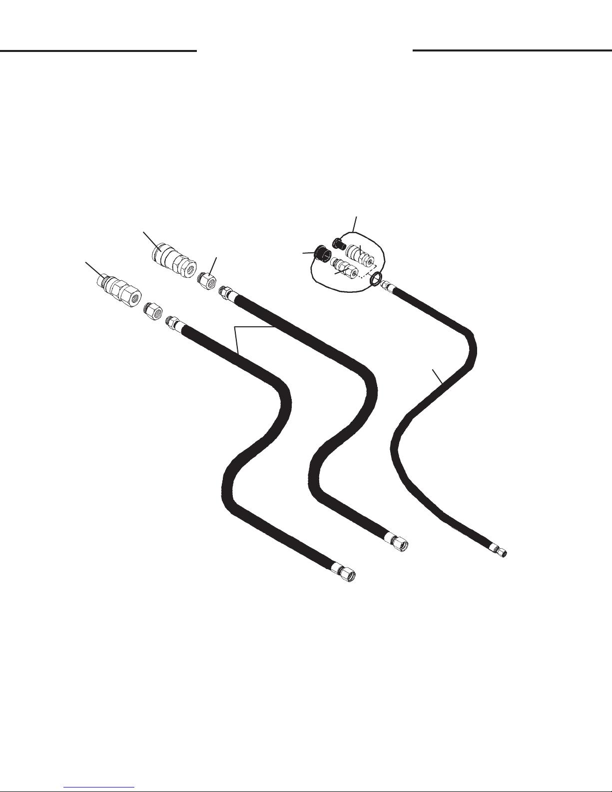
HYDRAULIC ASSEMBLY
HYDRAULIC ASSEMBLIES FOR HIGH FLOW DRIVES
8
2
7
1
9
3
6
5
4
10803 10-12-06

E
E
HYDRAULIC ASSEMBLY
HYDRAULIC ASSEMBLIES FOR HIGH FLOW DRIVES
HYDRAULIC KIT #105779
NO REQ'D PART NO. DESCRIPTION
1 1 19638 Male Coupler .75” Body 12FBo
2 1 22520 Female Coupler .75” Body 12FBo
3 2 37060 Hose Assembly .75” X 88” 12MBo-12FJX
4 1 38151 Hose Assembly .38” X 94” 6FJX-8MBo
5 1 84923 Male Coupler .38” Body 8FBo
6 1 32549 Dust Cap
HYDRAULIC KIT #105780
NO REQ'D PART NO. DESCRIPTION
1 1 84922 Male Coupler .62” Body 12FBo
2 1 84921 Female Coupler .62” Body 12FBo
3 2 37769 Hose Assembly .75” X 108” 12MBo-12FJX
4 1 38162 Hose Assembly .38” X 112” 6FJX-8MBo
5 1 84923 Male Coupler .38” Body 8FBo
6 1 32549 Dust Cap
HYDRAULIC KIT #105781
NO REQ'D PART NO. DESCRIPTION
1 1 22519 Male Coupler .50” Body 12FBo
2 1 22518 Female Coupler .50” Body 12FBo
3 2 37060 Hose Assembly .75” X 88” 12MBo-12FJX
4 1 38151 Hose Assembly .38” X 94” 6FJX-8MBo
5 1 84923 Male Coupler .38” Body 8FBo
6 1 32549 Dust Cap
HYDRAULIC KIT #105782
NO REQ'D PART NO. DESCRIPTION
1 1 19638 Male Coupler .75” Body 12FBo
2 1 22520 Female Coupler .75” Body 12FBo
3 2 37060 Hose Assembly .75” X 88” 12MBo-12FJX
4 1 38151 Hose Assembly .38” X 94” 6FJX-8MBo
7 1 84928 Female Coupler .38” Body 8FBo
8 1 32548 Dust Plug
HYDRAULIC KIT #105783
NO REQ'D PART NO. DESCRIPTION
1 1 16434 Male Coupler 1.00” Body 16FBo
2 1 16433 Female Coupler 1.00” Body 16FBo
3 2 37060 Hose Assembly .75” X 88” 12MBo-12FJX
4 1 38151 Hose Assembly .38” X 94” 6FJX-8MBo
5 1 14176 Male Coupler 50” Body 8FBo
6 1 17921 Dust Cap
9 2 30292 Straight Adapter 12FBo-16MBo
10804 10-12-06

E
MOUNTING KIT INSTALLATION
WHEEL KIT ASSEMBLY #24518
10
11
9
E
7
1
2
3
4
12
5
6
13
8
14
15
16
15
10041
6-25-10-2

E
MOUNTING KIT INSTALLATION
WHEEL KIT ASSEMBLY #24518
ITEM REQ’D PART NO. DESCRIPTION
1 1 101414 Spindle Dust Cap
2 1 10047 1.00” UNC Castle Nut
3 1 1706 1.00” Hard Flat Washer
4 1 33715 Tapered Roller Bearing
5 1 1614 Cotter Pin
6 1 33714 Tapered Roller Bearing
7 1 15511 Seal
8 1 101115 Wheel Yoke
9 1 24513 Support Arm
10 5 1092 .50” UNC x 2.00 Hex Capscrew, Grade 8
11 10 1516 .50” Hard Flat Washer
12 1 24530 .38” x 9.00” x 21.00 Plate
13 5 1841 .50” UNC Locknut, Grade 8
14 1 101195 Foam Filled Wheel & Tire Assembly
1 6616 Replacement Zerk
15 1 10105 Wheel Shaft/Nut Assembly
E
16 Varies 6562 Spring Washer
10042
6-25-10-2

F
F
INSTALLATION INSTRUCTIONS
GENERAL INFORMATION
The following instructions will help you to mount your rotary cutter onto your
skid-steer loader. The rotary cutter uses the quick-attach system for ease of installation. Therefore, if you know how to attach your loader bucket, attaching the rotary cutter
should prove no problem.
Remember to read all safety warnings, decals and operating instructions before
operating the attachment. If there is any portion of this manual that you do not understand, contact your dealer.
DANGER! TO AVOID SERIOUS PERSONAL INJURY OR DEATH THE BRAD-
CO ROTARY CUTTER MUST NOT BE ATTACHED TO ANY POWER
UNIT THAT DOES NOT HAVE A SHATTERPROOF DOOR (OR FRONT
SHIELD) INSTALLED.
WARNING! OPERATING THE STANDARD FLOW ROTARY CUTTER ON A HIGH
FLOW HYDRAULIC SYSTEM MAY CAUSE SEVERE INJURY OR DEATH
TO THE OPERATOR OR BYSTANDERS DUE TO THE INCREASED
RPM. DO NOT OPERATE THE STANDARD FLOW ROTARY CUTTERS
ON HIGH FLOW HYDRAULIC SYSTEMS.
INSTALLATION INSTRUCTIONS
NOTE: Before attaching the rotary cutter to your skid-steer loader, make sure a shatterproof door (or front shield) has been installed onto the front of your skid-steer loader. This
is required to protect the operator from possible thrown objects.
1. Remove the shipping banding from around the rotary cutter and skid.
2. Remove any attachments from the front of the loader.
3. Following all standard safety practices and the instructions for installing an attachment
in your skid-steer operator's manual, install the rotary cutter onto your skid-steer.
NOTE: It is important to make sure the locking mechanism on your quick attach is
engaged, therefore locking the attachment onto the skid-steer.
4. Connect the Lift Limiting Chain to your skid-steer. The back of the rotary cutter should
never be more than 1 foot off the ground for proper and safe cutting. (Raise the unit
to 1 foot above ground level. Route the end of the Lift Limiting Chain through the "D"
ring on the back of the rotary cutter and then through the tie down mechanism(s)
on the front of your skid-steer loader. Tie the chain securely back to itself with the
shackle provided, to limit the lifting capabilities of the cutter to 1 foot maximum.)
5. Lower the unit to the ground and remove the key.
6. After making sure that there is not any foreign matter on the hydraulic couplers,
connect the couplers to the auxiliary hydraulic system of your skid-steer loader.
IMPORTANT: Do not operate the BRADCO standard ow rotary cutter on High Flow
Hydraulic systems. Doing so will void the standard ow rotary cutter warranty.
9021 10-11-06-3

G
G
OPERATING INSTRUCTIONS
ROTARY CUTTER
GENERAL INFORMATION
The BRADCO rotary cutter is perfect for cutting tall grass and brush up to
4" in diameter.
The rotary cutter attaches to the toolbar/quick-attach mechanism of your
skid-steer loader. Due to this arrangement, thorough knowledge of the skid-steer
controls is necessary for machine operation. Read and understand your skidsteer operator's manual for information regarding skid-steer operation before
attempting to use the rotary cutter.
Follow all installation instructions in Section F for the proper installation of
the unit onto your skid-steer before attempting to operate your rotary cutter.
OPERATING TIPS
• Increase the life of your bi-directional blades by cutting brush in one direction and cutting grass and smaller vegetation in the other. (This will keep
the blades sharp for cutting grass.)
• If your preferred direction of blade rotation is not set up correctly for your
skid-steers "detent", the hydraulic hoses may be reversed at the motor
end.
• Continuous rotation of the blades is required during operation to prevent
overheating of the hydraulic system. The rotary cutter is equipped with a
blade rotation indicator disk to assist in monitoring blade rotation. If the
rotary cutter stalls, disengage auxiliary hydraulics, and remove cutter from
debris before restarting.
• Engage and disengage the hydraulic system with the skid-steer at idle.
WARNING! Before leaving the operator's seat: Lower the lift arms against
frame and place unit on the ground. Disengage auxiliary hydraulics. Stop Engine. Engage parking brake. Remove the key.
DANGER! ROTATING BLADE HAZARD! STAY BACK!
OBJECTS CAN BE THROWN!
DO NOT operate near bystanders.
DO NOT place hands or feet under deck while in operation or
with engine running.
DO NOT operate without a shatterproof door (or front shield)
installed on loader.
WARNING! Operatingthestandardowrotarycutteronahighowhy-
draulic system may cause severe injury or death to the operator or bystanders due to the increased RPM. Do NOT operate
thestandardowrotarycuttersonhighowhydraulicsystems.
WARNING! Lift limiting chain must be properly installed before operation.
9022 10-11-06-4

G
G
OPERATING INSTRUCTIONS
ROTARY CUTTER
CUTTING OPERATION
1. Raise the back of the unit off of the ground approximately 4" to allow the
material to clear from under the cutting deck as you travel forward.
2. Place the front skid shoes 1-2 inches off the ground. This is the preferred
position for cutting grass and heavy vegetation.
• Never drive your skid-steer with the front of the rotary cutter tilted to the point
your view is obstructed. Always make sure you can see what you are cutting.
• Check the work area. Never operate the rotary cutter in populated areas
where thrown objects could injure persons or damage property.
• Never raise the unit and expose yourself or anyone else to the rotating
blades. If you can see the blades then the back of the unit is raised too high.
3. Activate the auxiliary hydraulics with the engine at idle. Increase engine
speed.
4. Be sure the rotary cutter is operating smoothly and at full speed, and then
start forward travel while monitoring blade rotation.
NOTE: The rotary cutter has a window in the motor cover shield so the
operator can see the blade rotation indicator disk. This disk should always
be rotating during operation to prevent a drop in hydraulic pressure or
overheating of the hydraulic system.
CUTTING LARGE BRUSH UP TO 3-4" IN DIAMETER:
When cutting large brush, roll the front of the rotary cutter up 1-2 feet. DO
NOT LIFT THE BACK OF THE CUTTER! Slowly drive into the tree and use the
hydraulic tilt function on the skid-steer to bend or push the tree over. As the tree
bends, the blades will cut it off. The tree can now be mulched by rotating the front up,
drive forward several feet, roll the front down onto the tree and backdrag. Repeat, if
necessary. Remember do not lift the back of the cutter.
AVOID STALLING ROTARY CUTTER: Continuous rotation is required to prevent
overheating of the hydraulic system. The rotary cutter is equipped with a blade
rotation indicator disk to assist in monitoring blade rotation. If the rotary cutter stalls,
see "TO RESTART BLADE ROTATION".
TO RESTART BLADE ROTATION: Return engine speed to idle and disengage
auxiliary hydraulics. Remove rotary cutter from debris. Engage auxiliary hydraulics to
start blade rotation. (Be sure the rotary cutter is operating smoothly and at full
speed, and then start forward travel while monitoring blade rotation.)
9023
11-2-04-3

G
G
OPERATING INSTRUCTIONS
ROTARY CUTTER
REPEATED STALLING OF ROTATING BLADES: Return engine speed to idle
and disengage auxiliary hydraulics. Remove rotary cutter from debris. Review
operating conditions and the size/density of material being cut. Make necessary
corrections. Engage auxiliary hydraulics to start blade rotation. (Be sure the
rotary cutter is operating smoothly and at full speed, and then start forward travel
while monitoring blade rotation.)
TROUBLESHOOTING OPERATING CONDITIONS:
Below are listed a few operating conditions that may cause repeated
stalling of your rotary cutter, and suggestions on how to correct them.
GRASS TOO LONG OR THICK: If cutting heavy vegetation, you may need to slow
travel speed or make smaller passes (less than full cut) to prevent overloading and
stalling the unit.
BRUSH TOO BIG IN DIAMETER: The rotary cutter is NOT designed to cut trees
larger than 3-4" in diameter. If brush is smaller than 3-4" in diameter and the cutter is
stalling, check sharpness of the blades (see "Maintenance" Section L) and cut using
the procedure described earlier in this section for "Cutting Large Brush".
BRUSH TOO THICK OR HEAVY: If cutting heavy or thick brush, you may need to
slow travel speed or make smaller passes (less than full cut), to prevent overloading.
If the blades seem to be unable to handle the volume of brush, slow down the travel
speed until the unit reaches full speed before proceeding.
SCALPING THE GROUND or BOTTOMING OUT: Be aware of changes in the
terrain. Stay alert for drop-off and holes. Check the terrain and the deck position
before restarting and continuing cutting.
STRIKING FOREIGN OBJECTS: Stay alert for rocks, fencing, abandoned
wells, septic tanks or other foreign objects. If the rotary cutter comes into contact
with a foreign object, stop the unit, shut off the engine and disconnect the hydraulic couplers from the skid-steer. Inspect the unit and repair any damage
before restarting and continuing cutting. (Never try to weld or straighten damaged blades.) Inspect the work area for any other items, and if they are too large to
be removed from the area, they should be flagged clearly.
9024
11-2-04-2

H
H
LUBRICATION
GENERAL INFORMATION
Economical and efficient operation of any machine is dependent upon
regular and proper lubrication of all moving parts with a quality lubricant. Neglect
leads to reduced efficiency, wear, breakdown, and needless replacement of parts.
WEEKLY
The oil level in the gear box should be checked once a week. Fill as
necessary with 80-90 weight gear lubricant.
TO CHECK:
Remove pipe plug from end of gearbox. Lubricant should be at the same
level as the plug.
TO ADD:
Remove pipe plug from end of gearbox. Remove filler plug from top end of
gearbox and add 80-90 weight gear lubricant up to the same level as the pipe
plug. Replace pipe plug and filler plug.
IMPORTANT: DO NOT OVERFILL, AS TOO MUCH LUBRICANT MAY RUPTURE THE GEAR BOX SEALS.
FILLER PLUG
GEARBOX
PIPE PLUG
ADD LUBRICANT TO
THIS LEVEL
9011
4-15-03

L
L
MAINTENANCE
ROTARY CUTTERS
GENERAL INFORMATION
Regular maintenance is the key to long equipment life and safe operation. Maintenance requirements have been reduced to an absolute minimum. However,
it is very important that these maintenance functions be performed as described below.
WARNING! Avoid serious injury. Lower the rotary cutter to the ground, set the
parking brake, stop the skid-steer engine, and remove the key before
leaving the operator's seat. If unit must be left raised for maintenance,
block the unit securely to prevent accidental release of the lifting mechanism. Disconnect the hydraulic couplers.
DAILY
• Check skid-steer loader hydraulic system to ensure an adequate level of hydraulic oil.
• Check gearbox castle nut and torque to min. 250 - max 350 ft. lbs.
• Check mounting hardware on blades and torque to 450 ft. lbs.
• Check all other hardware and tighten, if necessary. See Section O.
• Check hydraulic system for hydraulic oil leaks.
• Check gearbox power shaft for foreign material wrapped around the shaft and re-
move, if necessary.
• Check blades for damage and replace or sharpen as needed.
• Check all safety guards and ensure that all devices are installed correctly.
• Check for missing or illegible Safety / Warning Decals.
WARNING! Escaping fluid under pressure can have sufficient force to penetrate the
skin, causing serious personal injury. Fluid escaping from a very small
hole can be almost invisible. Use a piece of cardboard or wood, rather
than hands to search for suspected leaks.
Keep unprotected body parts, such as face, eyes, and arms as far away
as possible from a suspected leak. Flesh injected with hydraulic fluid may
develop gangrene or other permanent disabilities.
If injured by injected fluid, see a doctor at once. If your doctor is not
familiar with this type of injury, ask him to research it immediately to
determine proper treatment.
CARDBOARD
HYDRAULIC HOSE
OR FITTING
MAGNIFYING GLASS
• Check oil level in gearbox and add if necessary. (See Section H)
EVERY 40 HOURS
9013
11-2-04-3

L
L
MAINTENANCE
ROTARY CUTTERS
WARNING! Avoid serious injury. Lower the rotary cutter to the ground, set
the parking brake, stop the skid-steer engine, and remove the
key before leaving the operator's seat. If unit must be left
raised for maintenance, block the unit securely to prevent
accidental release of the lifting mechanism. Disconnect the
hydraulic couplers.
REPLACING BLADES
When replacing, changing, or sharpening the blades, the unit must be
blocked securely off the ground to gain access to the blades.
The blades should be inspected regularly (every 8 hours) to ensure they
are sharp, tightened correctly, and intact. Always replace both blades at the same
time and NEVER try to weld or straighten damaged blades, as loss of blade integrity may result.
Removing Blades:
1. With unit securely blocked off the ground and hydraulic couplers discon-
nected, loosen the capscrews on the blade access cover and swing cover
open.
2. Position one of the blades under the
access panel and remove the cotter
pin and special nut. You can now
remove the blade mounting bolt and
the blade.
3. Repeat step #2 for the remaining
blade.
Installing Blades:
1. With unit securely blocked off the
ground and hydraulic couplers dis-
connected, loosen the capscrews on
the blade access cover and swing
cover open.
2. Position the blade with the key of the
mounting bolt in alignment with the key
way, and either prop up in place or
have an assistant hold in place while
the special nut is installed onto the
bolt through the blade access panel.
Torque nut to 450 ft. lbs. and install
cotter pin.
REMOVE COTTER
PIN
BLADE ACCESS
COVER
SPECIAL
NUT
BLADE
3. Repeat step #1 for the second blade.
9014
11-2-04-3

L
L
MAINTENANCE
ROTARY CUTTERS
WARNING! Avoid serious injury. Lower the rotary cutter to the ground,
set the parking brake, stop the skid-steer engine, and remove
the key before leaving the operator's seat. If unit must be left
raised for maintenance, block the unit securely to prevent
accidental release of the lifting mechanism. Disconnect the
hydraulic couplers.
REPLACING HYDRAULIC MOTOR
When replacing the hydraulic motor the unit should be setting on the ground
with the hydraulic couplers disconnected.
NOTE: Field replacement of the internal motor seals voids warranty.
1. With unit setting on the ground and hydraulic couplers disconnected, tag and
disconnect the hydraulic hoses and ttings from the hydraulic motor. Note
the hose routing for re-installation.
2. Loosen the four sockethead capscrews on the coupler and slide the motor
out of the coupler.
3. Remove the capscrews holding the motor to the motor mounting plate(s),
and remove the motor.
4. Install the new motor onto the mounting plate(s) using the existing hardware.
5. Slide the motor with the mounting plate(s) into the coupler and retighten the
sockethead capscrews. Torque all hardware to specication. See Section O.
6. Re-connect the hydraulic hoses and ttings to the new motor.
STANDARD FLOW
CUTTER SHOWN
BLADE ROTATION
INDICATOR
SOCKET HEAD
CAPSCREWS
HYDRAULIC
MOTOR
TAG HYDRAULIC
HOSES
COUPLER
MOTOR MOUNTING
PLATE
.50" UNC X 1.75" CAPSCREW
.50" LOCK WASHER
.50" UNC HEX NUT
9015 10-11-06-3

L
MAINTENANCE
ROTARY CUTTERS
WARNING! Avoid serious injury. Lower the rotary cutter to the ground, set
the parking brake, stop the skid-steer engine and remove the
key before leaving the operator's seat. If unit must be left
raised for maintenance, block the unit securely to prevent
accidental release of the lifting mechanism. Disconnect the
hydraulic couplers.
REPLACING GEARBOX/MOTOR COUPLER
When replacing the coupler the unit should be setting on the ground with
the hydraulic couplers disconnected.
1. With unit setting on the ground and hydraulic couplers disconnected,
loosen the four sockethead capscrews on the coupler and remove the
motor with the motor mounting plate still installed.
2. Remove the roll pin holding the
coupler to the gearbox, and the three
capscrews holding the blade rotation
indicator to coupler.
ROLL
.25" UNC X .50"
CAPSCREWS
PIN
COUPLER
HYDRAULIC
MOTOR
L
3. Replace the coupler on the gearbox
shaft, and reinstall the roll pin and the
blade rotation indicator using the
existing hardware.
4. Reinstall the motor into the coupler,
and retighten the sockethead cap-
screws. Torque to specification.
See Section O.
GEARBOX
BLADE
ROTATION
INDICATOR
SOCKETHEAD
CAPSCREWS
WARNING! Avoid serious injury. Lower the rotary cutter to the ground, set the
parking brake, stop the skid-steer engine, and remove the key
before leaving the operator's seat. If unit must be left raised for
maintenance, block the unit securely to prevent accidental release
of the lifting mechanism. Disconnect the hydraulic couplers.
REPLACING GEARBOX
When replacing the gearbox, the unit must be blocked securely off the ground
to gain access to the castle nut holding the stump jumper to the lower end of the
gearbox.
1. With unit securely blocked off the ground and hydraulic couplers discon-
nected, remove the cotter pin and castle nut holding the stump jumper to
the lower end of the gearbox. NOTE: Be prepared for the weight of the
stump jumper with the blades attached to fall when the castle nut is
removed.
9016
11-3-04-2

L
L
MAINTENANCE
ROTARY CUTTERS
2. Remove the roll pin holding the coupler to the gearbox and the three cap-
screws holding the blade rotation indicator to coupler.
3. Loosen the four socket head capscrews on the coupler and slide the cou-
pler along with the motor assembly off of the gearbox drive shaft.
4. Remove the four capscrews securing the gearbox to the rotary cutter
deck, and lift the gearbox off the cutter.
5. Install the new gearbox with the existing hardware removed in Step #4.
6. Position the stump jumper onto the lower end of the gearbox and reinstall
the castle nut. Torque nut to 230 ft. lbs. Continue to tighten until the next
nut castellation aligns with cross pin hole in the output shaft. Final torque
range must be between 240 - 250 lt. lbs. Reinstall cotter pin.
7. Install the blade rotation indicator onto the gearbox followed by the cou-
pler/motor assembly.
8. Reinstall the .25" capscrews securing the blade rotation indicator to the
coupler, reinstall the roll pin, and tighten the four sockethead capscrews
specication. See Section O.
9. Check lubrication level in the gearbox and add as needed. See Section H.
STANDARD FLOW
CUTTER SHOWN
GEARBOX
BLADE
ROTATION
INDICATOR
ROLL
PIN
REMOVE COUPLER AND
MOTOR ASSEMBLY
TOGETHER
SOCKETHEAD
CAPSCREWS
.25" UNC X .50" CAPSCREWS
.25" LOCK WASHERS
9017 10-11-06-4

M
M
STORAGE
ROTARY CUTTER
GENERAL INFORMATION
The following storage procedure will help you to keep your rotary cutter in
top condition. It will also help you get off to a good start the next time your cutter
is needed. We therefore strongly recommend that you take the extra time to
follow these procedures whenever your unit will not be used for an extended
period of time.
PREPARATION FOR STORAGE
1. Clean the unit thoroughly, removing all mud, dirt, and grease.
2. Sharpen or replace blades. Replace all blades at the same time and do
not try to weld or straighten damaged blades; loss of integrity may result.
3. Inspect for visible signs of wear, breakage, or damage. Order any parts
required, and make the necessary repairs to avoid delays when starting next
season. NOTE: Purchase only approved replacement parts from your
authorized BRADCO dealer.
4. Tighten all loose nuts, capscrews, and hydraulic connections.
5. Check the gear box for proper lubricant level.
6. Connect the hydraulic couplers together to protect the hydraulic system
from contaminates.
7. Touch up all unpainted and exposed areas with paint, to prevent rust.
8. Replace decals if damaged, or in unreadable condition.
9. Apply a rust-preventive spray to all moving parts and to the bottom of the
deck.
10. Store the unit in a dry and protected place. Leaving the unit outside will
materially shorten its life.
REMOVING FROM STORAGE
1. Remove all protective coverings.
2. Check hydraulic hoses for deterioration, and replace if necessary.
3. Check all nuts and bolts for proper tightness, especially those securing
the motor, gearbox and blades.
9010
6-4-03-2

N
N
TROUBLESHOOTING
ROTARY CUTTER
PROBLEM
Loss of Power.
POSSIBLE CAUSE
Skid-steer auxiliary valve
not engaged.
Relief valve setting
adjusted too low.
Inadequate hydraulic
flow from skid-steer.
Low oil supply.
Couplers not engaged.
Air in hydraulic lines.
Broken hose.
Obstruction in hydraulic
lines.
Loose or damaged
hydraulic connection.
Broken gearbox pin.
POSSIBLE REMEDY
Engage auxiliary valve.
Refer to skid-steer operator's
manual.
Check hydraulic flow to rotary
cutter.
Add oil.
Engage couplers.
Activate system until air is
purged from system.
Replace damaged hose.
Remove obstruction and
replace if necessary.
Tighten or replace fittings.
Replace pin.
PROBLEM
Excessive vibration.
PROBLEM
Leaking oil.
Hydraulic motor damaged or seal blown.
POSSIBLE CAUSE
Dull, broken or damaged
blades.
Bent gearbox shaft.
Stump Jumper out of
balance.
POSSIBLE CAUSE
Loose or damaged
hydraulic line.
Ruptured gearbox seal.
Bent gearbox shaft.
Loose or missing gearbox plug.
Call Bradco service department for instructions.
POSSIBLE REMEDY
Sharpen or replace.
Call Bradco service department for instructions.
Call Bradco service department for instructions.
POSSIBLE REMEDY
Tighten or replace.
Call Bradco service department for instructions.
Call Bradco service department for instructions.
Tighten or replace.
Hydraulic motor damaged or seal blown.
Call Bradco service department for instructions.
9012
11-3-04-2

O O
BOLT TORQUE
GENERAL TORQUE SPECIFICATION TABLE
Use the foll owing torques when special torques are not given. These values appl y to fasteners as
received from suppliers, dry, or when lubricated with normal engine oil. They do not apply if special
graphi ted or moly disulphi de greases or other extreme pressure lubricants are used. T his appli es to both
UNF and UNC threads. Remember to always use grade fi ve or better when replacing bolts.
SAE Grade No. 2 5 8*
Bolt head identification
marks as per grade.
NOTE: Manufactur ing
Marks Will Vary
Inches Millimeters Min. Max. Min. Max. Min. Max. Min. Max. Min. Max. Min. Max.
5/16 7.94 10 12 13.6 16.3 17 20.5 23.1 27.8 24 29 32.5 39.3
7/16 11.11 30 25 40.7 47.4 54 64 73.2 86.8 70 84 94.9 113.9
9/16 14.29 65 75 88.1 101.6 110 132 149.2 179.0 160 192 217.0 260.4
1-1/8 25.58 - - - - 800 880 1084.8 1193.3 1280 1440 1735.7 1952.6
1-1/4 31.75 - - - - 1120 1240 1518.7 1681.4 1820 2000 2467.9 2712.0
1-3/8 34.93 - - - - 1460 1680 1979.8 2278.1 2380 2720 3227.3 3688.3
1-1/2 38.10 - - - - 1940 2200 2630.6 2983.2 3160 3560 4285.0 4827.4
TORQUE TORQUE TORQUE
Bolt Size
1/4 6.35 5 6 6.8 8.13 9 11 12.2 14.9 12 15 16.3 30.3
3/8 9.53 20 23 27.1 31.2 35 42 47.5 57.0 45 54 61.0 73.2
1/2 12.70 45 52 61.0 70.5 80 96 108.5 130.2 110 132 149.2 179.0
5/8 15.88 95 105 128.7 142.3 150 180 203.4 244.1 220 264 298.3 358.0
3/4 19.05 150 185 203.3 250.7 270 324 366.1 439.3 380 456 515.3 618.3
7/8 22.23 160 200 216.8 271.0 400 480 542.4 650.9 600 720 813.6 976.3
1 25.40 250 300 338.8 406.5 580 696 786.5 943.8 900 1080 1220.4 1464.5
Pounds Feet Newton-Meters Pounds Feet
METRIC BOLT TORQUE SPECIFICATIONS
Coarse Thread Fine Thread
Siz e of Screw Grade No. Ptich (mm) Pounds Fee t Ne wton-Meters Pitch (mm) Pounds Feet Newton-Me ters
5.6 3.6-5.8 4.9-7.9 - -
M6 8.8 1.0 5.8-9.4 7.9-12.7 - - -
10.9 7.2-10 9.8-13.6 - -
5.6 7.2-14 9.8-19 12-17 16.3-23
M8 8.8 1.25 17-22 23-29.8 1.0 19-27 25.7-36.6
10.9 20-26 27.1-35.2 22-31 29.8-42
5.6 20-25 27.1-33.9 20-29 27.1-39.3
M10 8.8 1.5 34-40 46.1-54.2 1.25 35-47 47.4-63.7
10.9 38-46 51.5-62.3 40-52 54.2-70.5
5.6 28-34 37.9-46.1 31-41 42-55.6
M12 8.8 1.75 51-59 69.1-79.9 1.25 56-68 75.9-92.1
10.9 57-66 77.2-89.4 62-75 84-101.6
5.6 49-56 66.4-75.9 52-64 70.5-86.7
M14 8.8 2.0 81-93 109.8-126 1.5 90-106 122-143.6
10.9 96-109 130.1-147.7 107-124 145-168
5.6 67-77 90.8-104.3 69-83 93.5-112.5
M16 8.8 2.0 116-130 157.2-176.2 1.5 120-138 162.6-187
10.9 129-145 174.8-196.5 140-158 189.7-214.1
5.6 88-100 119.2-136 100-117 136-158.5
M18 8.8 2.0 150-168 203.3-227.6 1.5 177-199 239.8-269.6
10.9 175-194 237.1-262.9 202-231 273.7-313
5.6 108-130 146.3-176.2 132-150 178.9-203.3
M20 8.8 2.5 186-205 252-277.8 1.5 206-242 279.1-327.9
10.9 213-249 288.6-337.4 246-289 333.3-391.6
BOLT TO RQUE SPECIFI CATIONS
Newton-Meters
* Thick Nuts must be used with Grade 8 bolts
Pounds Feet
Newton-Meters
6-8-95-2
3915

P
P
SPECIFICATIONS
ROTARY CUTTERS
C
A
E
D
B
SPECIFICATIONS AND DESIGN ARE SUBJECT TO CHANGE WITHOUT NOTICE AND WITHOUT LIABILITY THEREFOR.
SPECIFICATIONS
STANDARD HIGH FLOW
DESCRIPTION BC60 BC72 BC60* BC72 BC78
A. Overall Height................................22.50" ......... 22.50" ......... 22.50" .......... 22.50" ..........22.50"
B. Overall Width .................................72.00" ......... 85.00" ......... 72.00" .......... 85.00" ..........91.00"
C. Overall Length ..............................78.25" ......... 90.25" .........78.25" .......... 90.25" ..........96.00"
D. Cutting Width ................................. 60.00" ......... 72.00" .........60.00" .......... 72.00" ..........78.00"
E. Minimum Cutting Height 2.00" ........ 2.00" ............ 2.00 ............ 2.00" ............2.00" ............2.00"
(Skid Shoes on Ground)
Cutting Capacity (Max. Cutting Diameter) ....4.00" ........... 4.00" ........... 4.00" ............4.00" ............4.00"
Deck Thickness ................................. 1/4" Steel ....1/4" Steel .... 1/4" Steel .... 1/4" Steel .... 1/4" Steel
Recommended GPM ............................ 15-20...........18-22 ...........25-30 ...........32-40 .......... 32-40
Required Skid-Steer Lift Capacity ........1300# ..........1700#.......... 1300# .......... 1700# ..........1800#
Weight ..................................................1230# ..........1610#.......... 1230# .......... 1610# ..........1666#
* (SPECIFICATIONS FOR BC60 WITH SPECIAL MOTOR #106601 ONLY)
9025
11-3-04-2

Q
DECALS
DECAL PLACEMENT
GENERAL INFORMATION
The diagrams on this page show the location of the decals used on the
BRADCO Rotary Cutter. The decals are identied by their part numbers, with
reductions of the actual decals located on the following pages. Use this information to order replacements for lost or damaged decals. Be sure to read all decals
before operating the unit. They contain information you need to know for both
safety and longevity.
#40678
#40590
STANDARD
FLOW ONLY
#40151
#40676
Q
#40092
#40179
#40679
#40677
#40673
#4105
#40673
#4105
#4338
#40673
#40179
#40161
#40749
#40307
SERIAL NUMBER
TAG LOCATION
IMPORTANT: Keep all safety signs clean and legible. Replace all missing, illegible, or damaged
safety signs. When replacing parts with safety signs attached, the safety signs must also be
replaced unless otherwise noted.
REPLACING SAFETY SIGNS: Clean the area of application with nonammable solvent, then
wash the same area with soap and water. Allow the surface to fully dry. Remove the backing from
the safety sign, exposing the adhesive surface. Apply the safety sign to the position shown in the
diagram above, and smooth out any bubbles.
#40803
#40804
#40937
8905 10-11-06-4

Q
Q
DECALS
DANGER! ROTATING BLADE
PART #40673
WARNING! HIGH PRESSURE FLUID
PART #40151
SAFETY INSTRUCTIONS
PART #40677
WARNING! BEFORE LEAVING
OPERATOR'S SEAT
PART #40678
WARNING! LIFT LIMITING CHAIN
PART #40679
DANGER! GUARD MISSING
PART #40307
8906
6-4-03-2

Q
DANGER STAND CLEAR
DANGER STAND CLEAR
PART #4105
BLADE ROTATION INDICATOR
PART #40676
BC60
BC72 MODEL NUMBER
PART #40803
Q
DECALS
STAND CLEAR
STAND CLEAR
PART #40161
CAUTION! DO NOT OPERATE
PART #40590
BC72
BC60 MODEL NUMBER
PART #40804
BC78
BC78 MODEL NUMBER
PART #40937
MADE IN USA
MADE IN USA
PART #4338
ROTATION INDICATOR
PART #40749
BRADCO LOGO
PART #40092
BRADCO LOGO (VERTICAL)
PART #40179
8907 10-11-06-3

R
R
PREDELIVERY CHECKLIST
GENERAL INFORMATION
The following is a list of areas that should be inspected by the dealer prior to
delivery of the Rotary Cutter to the customer. The customer should check the list and
make sure that the dealer has completed the inspection. Completion of this checklist will help insure that the customer receives the rotary cutter in complete working
order, ready to install.
PREDELIVERY CHECKLIST - CHECK AND ADJUST AS NECESSARY
1. ______ Visually inspect the unit for bent, loose, cracked, damaged or missing
parts. Check for any other irregularities.
2. ______ Check and lubricate, if necessary. See "Lubrication" Section H.
3. ______ Check bolts for tightness. Retighten after the first four working hours,
and after every eight working hour intervals thereafter. See "Bolt
Torque", Section O.
4. ______ Check all hydraulic connections for leaks and all hoses for proper
positioning to reduce pinching, chafing and binding.
5. ______ Make sure decals are not damaged or missing and are in their cor-
rect location. See "Decals" Section Q.
6. ______ Make sure the customer has the necessary couplers to attach the unit
to the skid-steer auxiliary hydraulic couplers.
7. ______ Complete and return the manufacturer's "Warranty Validation Form"
and sign your dealership predelivery checklist.
9018
11-3-04-2

THIS PAGE
IS INTENTIONALLY
BLANK

Limited Warranty
Except for the Excluded Products as described below, all new products are warranted to be free from defects
in material and/or workmanship during the Warranty Period, in accordance with and subject to the terms and
conditions of this Limited Warranty.
1. Excluded Products. The following products are excluded from this Limited Warranty:
(a) Any cable, part that engages with the ground (i.e. sprockets), digging chain, bearing, teeth, tamping
and/or demolition head, blade cutting edge, pilot bit, auger teeth and broom brush that either constitutes or is part
of a product.
(b) Any product, merchandise or component that, in the opinion of Paladin Light Construction1, has been
(i) misused; (ii) modied in any unauthorized manner; (iii) altered; (iv) damaged; (v) involved in an accident; or (vi)
repaired using parts not obtained through Paladin Light Construction.
2. Warranty Period. The Limited Warranty is provided only to those defects that occur during the Warranty
Period, which is the period that begins on the rst to occur of: (i) the date of initial purchase by an end-user, (ii) the
date the product is rst leased or rented, or (iii) the date that is six (6) months after the date of shipment by Paladin
Light Construction as evidenced by the invoiced shipment date (the “Commencement Date”) and ends on the date
that is twelve (12) months after the Commencement Date.
3. Terms and Conditions of Limited Warranty. The following terms and conditions apply to the Limited Warranty
hereby provided:
(a) Option to Repair or Replace. Paladin Light Construction shall have the option to repair or replace
the product.
(b) Timely Repair and Notice. In order to obtain the Limited Warranty, (i) the product must be repaired
within thirty (30) days from the date of failure, and (ii) a claim under the warranty must be submitted to Paladin Light
Construction in writing within thirty (30) days from the date of repair.
(c) Return of Defective Part or Product. If requested by Paladin Light Construction, the alleged
defective part or product shall be shipped to Paladin Light Construction at its manufacturing facility or other location
specied by Paladin Light Construction, with freight PRE-PAID by the claimant, to allow Paladin Light Construction
to inspect the part or product.
Claims that fail to comply with any of the above terms and conditions shall be denied.
LIMITATIONS AND EXCLUSIONS.
THIS LIMITED WARRANTY IS IN LIEU OF ALL OTHER WARRANTIES, EXPRESS OR IMPLIED, INCLUDING
WITHOUT LIMITATION THE WARRANTIES OF MERCHANTABILITY, FITNESS FOR A PARTICULAR PURPOSE
AND ANY WARRANTY BASED ON A COURSE OF DEALING OR USAGE OF TRADE.
IN NO EVENT SHALL PALADIN LIGHT CONSTRUCTION BE LIABLE FOR CONSEQUENTIAL OR SPECIAL
DAMAGES.
IN NO EVENT SHALL PALADIN LIGHT CONSTRUCTION BE LIABLE FOR ANY LOSS OR CLAIM IN AN
AMOUNT IN EXCESS OF THE PURCHASE PRICE, OR, AT THE OPTION OF PALADIN LIGHT CONSTRUCTION,
THE REPAIR OR REPLACEMENT, OF THE PARTICULAR PRODUCT ON WHICH ANY CLAIM OF LOSS OR
DAMAGE IS BASED. THIS LIMITATION OF LIABILITY APPLIES IRRESPECTIVE OF WHETHER THE CLAIM
IS BASED ON BREACH OF CONTRACT, BREACH OF WARRANTY, NEGLIGENCE OR OTHER CAUSE AND
WHETHER THE ALLEGED DEFECT IS DISCOVERABLE OR LATENT.
1
Attachment Technologies Inc., a subsidiary of Paladin Brands Holding, Inc. (PBHI) is referred to herein as Paladin Light
Construction.
February 10, 2010
 Loading...