


REV. 5
OM495
617 TRENCHER
ALL SKID STEER
APPLICATIONS
5759 9-8-04-5
Printed in U.S.A.
COPYRIGHT 2-92
OPERATOR'S
75395
MANUAL
BRADCO®
P.O. Box 266 · Delhi, Iowa 52223 USA
(319) 922-2981 ·(800) 922-2981
Fax 319-922-2130


TABLE OF CONTENTS
Section
TO THE OWNER............................................................................................ A
SAFETY PRECAUTIONS ................................................................................B
To The Operator
Before You Start
During Trencher Operation
Transporting The Trencher
Maintaining The Trencher
INTERNATIONAL SYMBOLS ........................................................................ C
PREOPERATION ............................................................................................ D
General Information
Options
Trencher Major Component Nomenclature
MOUNTING KIT INSTALLATION...................................................................E
Mounting Kits
Mounting Instructions
TRENCHER INSTALLATION...........................................................................F
OPERATING INSTRUCTIONS ....................................................................... G
Controls
Operating Techniques
TRENCHER ASSEMBLY ..................................................................................I
DIGGING CHAIN OPTIONS............................................................................J
MAINTENANCE ..............................................................................................L
STORAGE ......................................................................................................M
TROUBLE SHOOTING ................................................................................... N
BOLT TORQUE .............................................................................................. O
SPECIFICATIONS ...........................................................................................P
DECALS ......................................................................................................... Q
PREDELIVERY CHECK LIST.......................................................................... R
LIMITED WARRANTY ................................................................................... S
4410
2-26-92-2


A
A
TO THE OWNER
GENERAL COMMENTS
Congratulations on the purchase of your new trencher! Your trencher
was carefully designed and manufactured to give you many years of dependable service. Your trencher will require some minor maintenance (such
as cleaning and lubricating) to keep it in top working condition. Be sure to
observe all safety precautions and maintenance procedures as described in
this manual.
ABOUT THIS MANUAL
This manual has been designed to help you do a better, safer job.
Read this manual carefully and become familiar with it's contents. Remem-
ber, never let anyone operate this trencher without reading the "Safety
Precautions" and "Operating Instructions" sections of this manual. (See
Sections B and G respectively.)
Unless noted otherwise, "right-hand" and "left-hand" sides are determined from the position of the skid steer operator sitting in the seat facing
forward.
SAFETY ALERT SYMBOL
This is the "Safety Alert Symbol" used by this industry. This
symbol is used to warn of possible injury. Be sure to read all
warnings carefully. They are included for your safety and for
the safety of others working with you.
SERVICE
When servicing your trencher, remember to use only manufacturer
replacement parts. Substitute parts may not meet the standards required
for safe, dependable operation.
To facilitate parts ordering, record the model and serial number of
your trencher in the space provided on this page. This information may be
obtained from the trencher identification plate located on the right side of
the trencher main frame.
MODEL DATE PURCHASED
SERIAL NO.
MOUNTED ON
Your parts dealer needs this information to insure that you receive the correct parts for your specific trencher.
4411
2-25-92-2


B
B
SAFETY PRECAUTIONS
TAKE NOTE! THIS SAFETY ALERT SYMBOL FOUND THROUGHOUT THIS
MANUAL IS USED TO CALL YOUR ATTENTION TO INSTRUCTIONS INVOLVING YOUR PERSONAL SAFETY OR OTHERS. FAILURE TO FOLLOW
THESE INSTRUCTIONS CAN RESULT IN INJURY OR DEATH.
THIS SYMBOL MEANS:
ATTENTION!
BECOME ALERT!
YOUR SAFETY IS INVOLVED!
SIGNAL WORDS: Note the use of signal words DANGER, WARNING, and CAU-
TION with the safety messages. The appropriate signal word for each has been
selected using the following guidelines:
DANGER: Indicates an imminently hazardous situation, which if not avoided, will
result in death or serious injury. This signal word is to be limited to the
most extreme situations, typically for machine components
which, for functional purposes, cannot be guarded.
WARNING: Indicates a potentially hazardous situation, which if not avoided, could
result in death or serious injury, and includes hazards that are
exposed when guards are removed. It may also be used to
alert against unsafe practices.
CAUTION: Indicates a potentially hazardous situation, which if not avoided, may
result in minor or moderate injury. It may also be used to alert
against unsafe practices.
6621
5-18-95

SAFETY PRECAUTIONS
TRENCHERS
GENERAL INFORMATION
This section is composed of various warnings and safety tips. Read and
learn all the information in this section before you attempt to use your tren-
cher. Also read your vehicle owner's manual before using your equipment. This
knowledge will help you operate your unit safely. Do not take this information
lightly, it is presented for your own benefit and for the benefit of others
working around you.
The "Safety Alert Symbol" , as previously described, will be used throughout
this manual. It will appear with one of the words
TION above it, and a safety message pertaining to the specific topic being covered.
Take the time to read these messages as you come across them.
TO THE OPERATOR
DANGER, WARNING, or CAU-
BB
The primary responsibility for safety with the equipment falls to the
operator. It is the skill, care, common sense, and good judgment of the
operator that will determine how efficiently and safely the job is performed.
Know your equipment before you start. Know its capabilities, dimensions,
and how to operate all the controls. Visually inspect your equipment before
you start, and never operate equipment that is not in proper working order
with all safety devices intact.
BEFORE YOU START
1.
2.
3.
Wear the right clothing and gear for the job. Protective equipment
such as hard hat, steel toed shoes, leather gloves, or safety glasses
may be in order. They can protect you from needless injury.
Do not wear loose clothing, or things such as rings and watches
around the equipment. They could get caught in moving parts, and
lead to serious injury or death.
Know your equipment inside and out. Know how to operate all con-
trols, and know emergency shutdown procedures. Make sure all
safety devices are in place and working.
4.
Keep all step plates, grab bars, pedals, and controls free of dirt,
grease, and oil. Keep equipment clean to help avoid injury from a fall
when getting on or off equipment.
4213
4-14-05-3

SAFETY PRECAUTIONS
TRENCHERS
BB
5.
6. Know your work area before you begin. Observe any potential hazard
7.
8.
9.
10. Always use your seatbelt and safety ROPS (Roll-Over-Protective
Do not use the trencher or crumber bar as a step, or grab the digging
chain when climbing on or off the trencher. Damage to the equip-
ment or personal injury could result.
areas such as soft ground, drop-offs, rocks and other obstacles.
Know where all utility lines are. Observe overhead electrical and
phone lines. Be sure equipment will safely clear them. Know the
location of underground cables, wires, gas and water lines, tanks,
etc. Contact with electrical lines could cause electrocution. Hitting a
gas line or underground tank could cause an explosion.
Be alert to others in the work area. Be sure others know when and
where you will be working. Make sure no one is underneath or behind
equipment.
Never try to board equipment while it's moving.
Structure) that are on the equipment. They could save your life in the
event of a mishap.
11.
12. Test all controls before you start. This includes safety equipment and
DURING TRENCHER OPERATION
1.
2.
3.
4.
Never take passengers on your equiment. There is no safe place for
riders.
devices.
Be alert to what is going on around you. Watch for others who may
not be watching out for themselves.
Never operate equipment while under the influence of alcohol, or
prescription drugs which could inhibit physical and or mental capac-
ity.
Stop the trencher and shut off the engine if anyone approaches the
equipment while it's in motion. They may not be familiar with the
equipment and get in the way of moving parts.
Be alert to changes in the work area. Changes in weather and soil
conditions could turn a safe work site into a hazardous area.
4214
2-25-92-2

SAFETY PRECAUTIONS
TRENCHERS
5. Keep equipment away from the trencher after it has been dug. The
weight of the unit could cause a cave-in.
BB
6.
7.
8.
9.
10.
TRANSPORTING THE TRENCHER
Never drop a boom with a rapidly moving digging chain on the
ground. The force of the trencher may cause the vehicle to move
suddenly and unexpectedly. Have the chain moving slowly, and
lower the boom carefully when starting a new cut.
Use caution when digging on a slope. The natural vibration of the
trencher will make the unit creep sideways downhill. Try to dig with
the trencher in a level position.
Never try to make sharp turns while trenching. The trencher boom
could become wedged in the trench and damaged.
Never attempt to free a stuck chain with the unit running. If the
trencher does become jammed, stop the unit and visually inspect the
situation.
Check the trencher frequently for loose hardware and fittings. The
natural vibration of the unit will cause fasteners to loosen during
operation.
1.
2. Use a SMV (Slow Moving Vehicle) sign on the vehicle when trans-
3.
4.
5. Follow factory recommended shut down procedures for equipment.
6.
Follow all federal, state, and local regulations when transporting the
unit on public roads.
porting. This will help alert others to your presence.
Be sure all lights and turn signals are in working order. Use them as
required.
When parking, park the unit on hard level ground and lower the tren-
cher boom. Block the wheels, and set the parking brake. Shut off the
engine.
Stop the trencher and vehicle before dismounting.
4215
2-26-92-2
SAFETY PRECAUTIONS
MAINTAINING THE TRENCHER
BB
TRENCHERS
1.
2. Lower the trenching boom, and shut off the engine before working on
3.
4. Use only manufacturer recommended replacement parts. Other parts
5.
6. Observe proper maintenance schedules. Proper maintenance can help
7.
Replace all safety shields and guards when performing maintenance.
Do not operate the trencher with protective equipment removed.
the unit. Never perform maintenance on a trencher while it is run-
ning.
Make sure all operating and residual pressures are relieved before
working on a hydraulic system. Shut engine off, and operate all the
controls to relieve any pressure.
may be substandard in fit and quality.
Do not set any relief valve higher than recommended by the manufac-
turer. Relief valves should be checked and adjusted only by a trained
service technician. Do not remove or block a relief valve.
prevent a hazardous condition.
Always wear safety goggles or glasses when working on equipment.
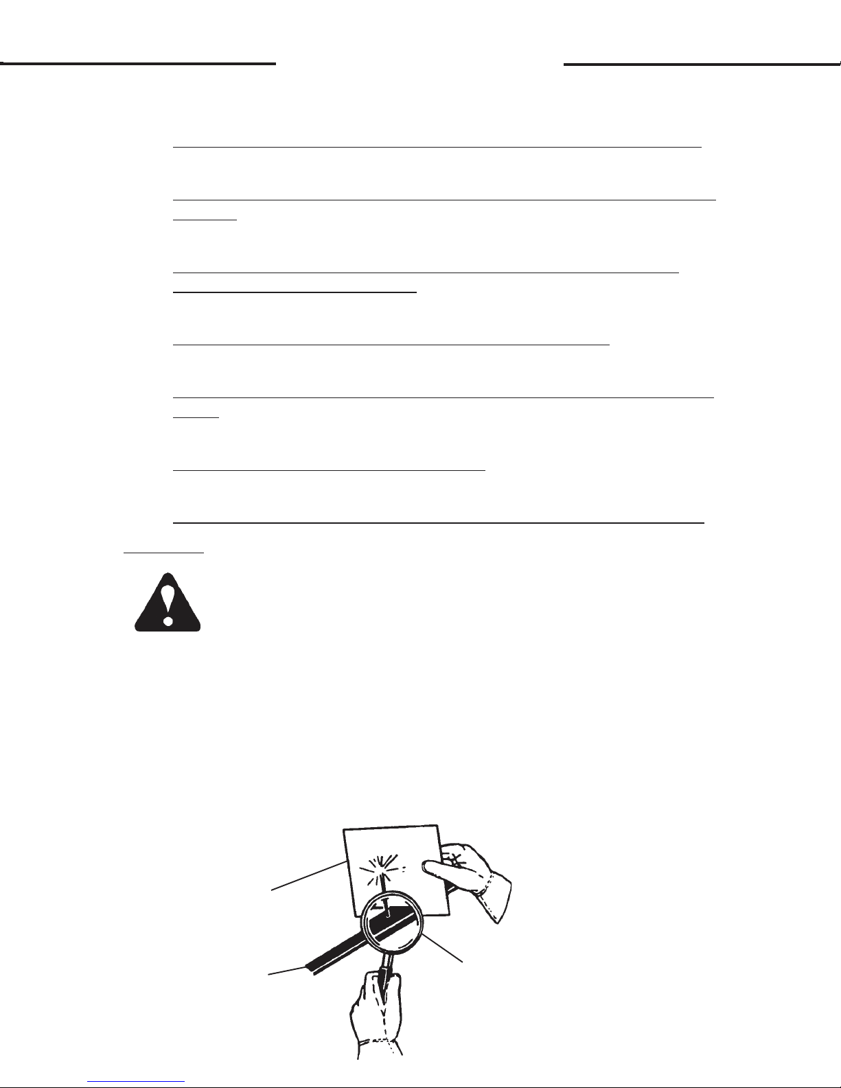
WARNING! Escaping fluid under pressure can have sufficient force to pen-
etrate the skin, causing serious personal injury. Fluid escaping
from a very small hole can be almost invisible. Use a piece of
cardboard or wood, rather than hands to search for suspected
leaks.
Keep unprotected body parts, such as face, eyes, and arms as
far away as possible from a suspected leak. Flesh injected
with hydraulic fluid may develop gangrene or other permanent
disabilities.
If injured by injected fluid, see a doctor at once. If your doctor
is not familiar with this type of injury, ask him to research it
immediately to determine proper treatment.
CARDBOARD
HYDRAULIC HOSE
OR FITTING
MAGNIFYING GLASS
4216
2-26-92-2

CC
INTERNATIONAL SYMBOLS
As a guide to the operation of your equipment, various international
symbols have been utilized on the instruments and controls. The symbols
are shown below with an indication of their meaning.
Engine speed Alternato r char g e
Hours recorded Power take-off (on)
Engine water temperature Power take-off (off)
Lights "Tortoise," slow or minimum setting
Horn "Hare," fast or maximum setting
Engine oil pressure Caution
Hazard warning Control lever operating direction
Axle connect Rock shaft (raised)
Axle disconnect Rock shaft (lowered)
Continuously variable Remote cylinder (extended)
Increase Remote cylinder (retracted)
Decrease Remote cylinder (FLOAT)
Diesel fuel Differential lock
Creeper range Read operators manual
High range Neutral
Low range Forward
Reverse
3869
4-14-94-2

DD
PREOPERATION
617 TRENCHER
GENERAL INFORMATION
The 617 trencher was designed to be easy to use and maintain. The
trencher mounts to the toolbar/attachment plate of the skid steer. The
mount incorporates the quick attach mechanism of the skid steer for fast,
easy mounting.
The trencher is powered by the skid steer's auxiliary hydraulic system. Your skid steer
trencher. If your unit does not have an auxiliary hydraulic system, contact
your skid steer dealer reguarding the possible addition of such a system.
An adapter is needed to attach the trencher to the skid steer. Most
trenchers are shipped with the adapter already mounted to the trencher. If
yours was not shipped this way, see Section E for mounting kit installation.
To install the trencher on the skid steer see Section F. Operating instructions are covered in Section G.
MUST have an auxiliary hydraulic system to run the
Use the chart below to determine which trencher assembly is needed
for your specific skid steer. A diagram and parts list of all mounting and
hydraulic kits can be found in Section E and the trencher assembly can be
found in Section I.
FIT-UP CHART
COMPLETE MOUNTING &
SKID STEER TRENCHER ASSEMBLY HYDRAULIC
(Including Mtg. & Hyd. Kit) KIT ONLY
ASV Posi-Track 4500/4520 79090 79093
Bobcat 700/800/2000 79090 79093
Case 1835C/1840/1845C 79090 79093
Case 75XT/85XT/90XT/95XT 79090 79093
Case 1845B 79092 79105
Daewoo 601/801 79090 79093
Ford NH 775/778/779/784/785 79094 79106
Ford NH 553/555 79095 79108
Ford NH 465/485/565/665/865/885/985 79090 79093
Gehl 4510/4610/4515/4615 79310 79314
Gehl 4625/5625 79309 79311
Gehl 5635/6635 79090 79093
Hydra Mac 1700/2250/2650 (Universal Hitch) 79090 79093
JCB 165 79090 79093
JCB 185/1105 85494 85493
John Deere 675 79095 79108
John Deere 875 79094 79106
John Deere 4475/6675/7775/8875 79090 79093
5760
11-16-98-3

D
D
PREOPERATION
617 TRENCHER
COMPLETE MOUNTING &
SKID STEER TRENCHER ASSEMBLY HYDRAULIC
(Including Mtg. & Hyd. Kit) KIT ONLY
Mustang 342/442/552/930/940/960 79096 79110
Mustang 2040/2050/2060/2070 Single Pin 79096 79110
Mustang 2040/2050/2060/2070 Dual Pin 79090 79093
Prime Mover L1300 79238 79240
Takeuchi TL26 79090 79093
Thomas T133 79097 79111
Thomas T173/T233 79098 79112
Thomas T173S IIQA/T243S IIQA/T245 79090 79093
Toyota 2SDK6/2SDK7/2SDK8 80268 80871
Trak 1050/1350 79097 79111
Trak 1650/2150 79098 79112
Trak 1300HD/1700HD/1300C/1700C 79090 79093
Trak 1500C/1800C/2300C 79090 79093
OPTIONS
Eventually you may wish to dig a trench of a depth or width other
than what your unit was originally equipped to dig. The 617 trencher can
be fitted with optional booms, digging chains, sprockets, and crumber assemblies to allow you to dig a variety of different sized trenches with a
digging chain option of a tooth every station or every other station. The
chart below will give you an idea of the different trench depths and widths a
properly equipped unit is capable of digging. For more detailed information
on trencher options see Sections I & J of this manual.
TRENCH DEPTHS* TRENCH WIDTHS
30" Depth 6.00" 8.00" 10.00" 12.00"
36" Depth 6.00" 8.00" 10.00" NA
42" Depth 6.00" 8.00" 10.00" NA
48" Depth 6.00" 8.00" NA NA
*Trench depths are given with the digging boom at an optimum 65°
diggging angle and the skid shoe touching the ground. Trenches of
various depths can be made by varying the digging angle and raising
the trencher up higher. These methods are less efficient however.
NOTE: The illustrations and data used in this manual were current
(according to the information available to us) at the time of
printing, however, we reserve the right to redesign and change the
trenchers as may be necessary without notification.
5761
11-16-98-3

D
PREOPERATION
TRENCHER MAJOR COMPONENT NOMENCLATURE
617 TRENCHER
GENERAL INFORMATION
The purpose of this page is to acquaint you with the trencher and the
names of its various components. This knowledge will be helpful when
reading through this manual or when ordering service parts.
HYDRAULIC MOTOR
SIDE SHIFT
CHAIN GUARD
CRUMBER BOOM
ADJUSTMENT
LOCKING PIN
SIDE SHIFT
MOUNTING
FRAME
D
BUILT-IN SKID
SHOE
CRUMBER BOOM
CRUMBER END
CRUMBER
SHOE
HEADSHAFT
AUGER
TOOTH
CHAIN TENSION
ADJUSTMENT
DIGGING CHAIN
DIGGING BOOM
5762
2-7-92

E
E
MOUNTING KIT INSTALLATION
TRENCHER MOUNTING KIT #79093
1
2
3
4
5
6
5763
6-13-94-2

E
E
MOUNTING KIT INSTALLATION
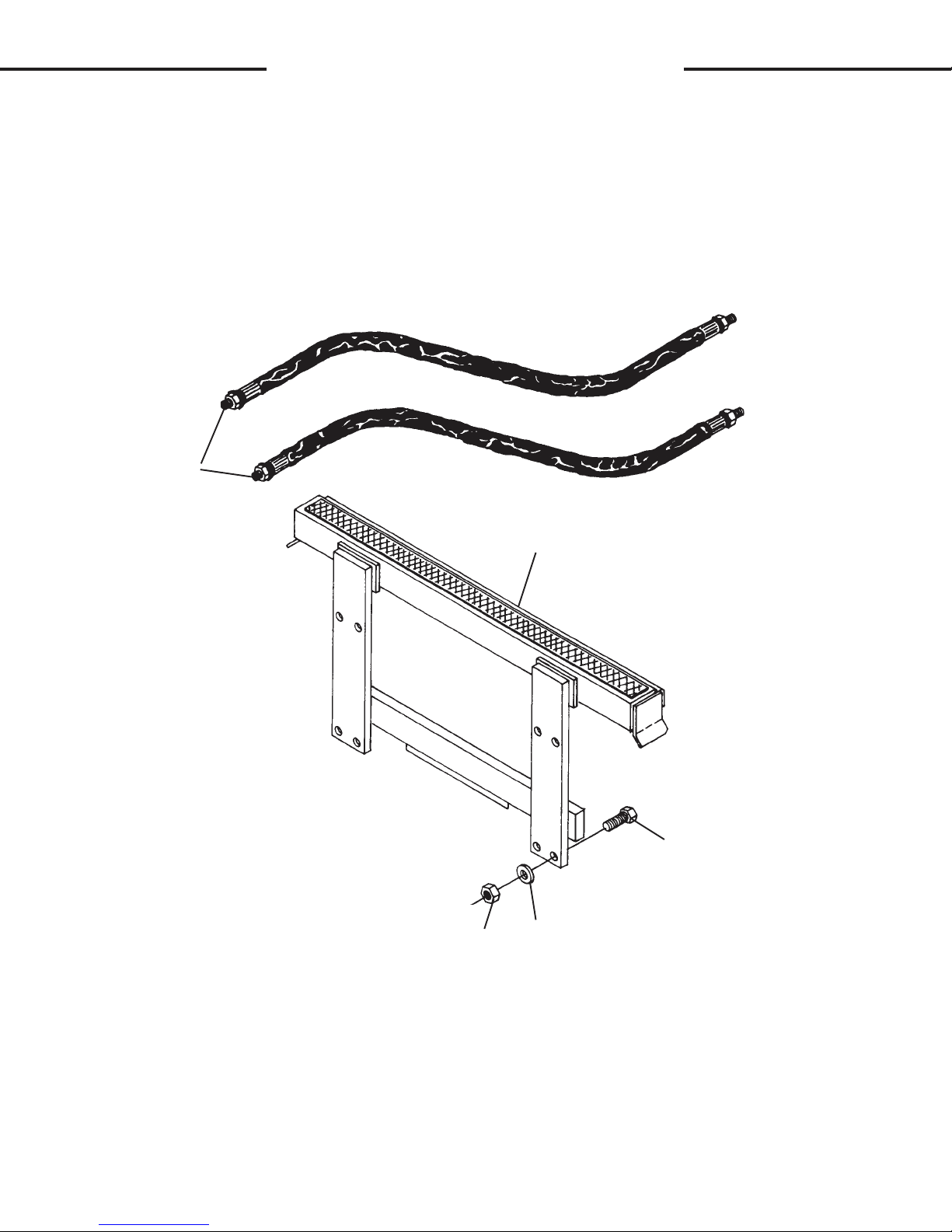
TRENCHER MOUNTING KIT #79093
NO REQ'D PART NO. DESCRIPTION
1 2 35792 Hose Assembly, .62" x 82"
(SAE 100R2-2Wire) 8MP-10MB-HS
2 1 78259 Right Trencher Mount
3 1 78260 Left Trencher Mount
4 8 1140 .75" UNC x 2.25" Hex Capscrew
5 8 1649 .75" Hard Flat Washer
6 8 1231 .75" UNC Hex Nut
5764
6-13-94-2

E
E
MOUNTING KIT INSTALLATION
TRENCHER MOUNTING KIT #79105
1
8
9
2
3
4
2
5
6
7
5765
2-13-92

E
E
MOUNTING KIT INSTALLATION
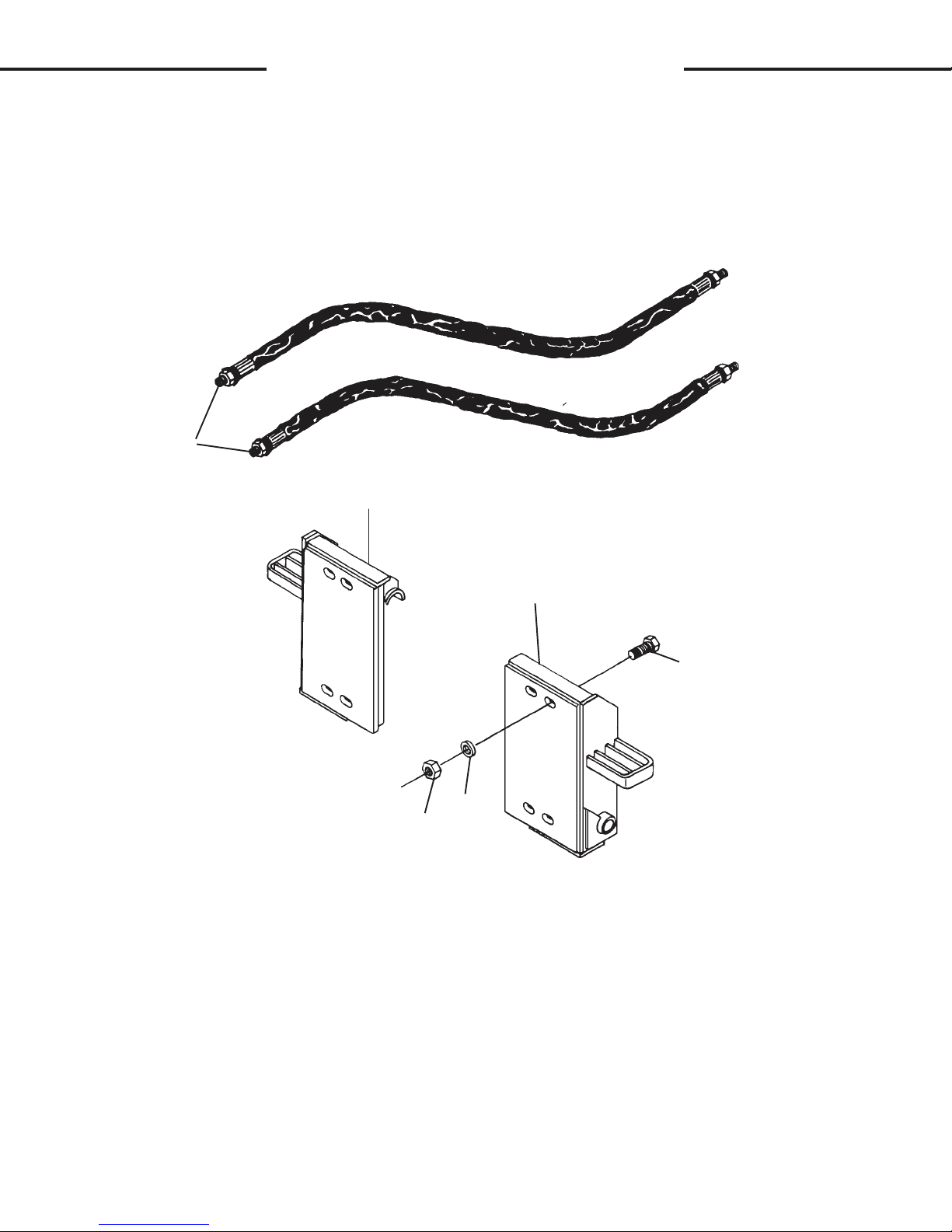
TRENCHER MOUNTING KIT #79105
NO REQ'D PART NO. DESCRIPTION
1 2 35792 Hose Assembly, .62" x 82"
(SAE 100R2-2Wire) 8MP-10MB-HS
2 2 59065 Pin
3 1 68935 Trencher Attaching Bracket
4 8 1089 .50" UNC x 1.25" Hex Capscrew
5 8 1516 .50" Flat Washer
6 8 1505 .50" Lock Washer
7 8 1228 .50" UNC Hex Nut
8 8 1649 .75" Hard Flat Washer
9 8 1137 .75" UNC x 1.50" Hex Capscrew
5766
2-13-92

E
E
MOUNTING KIT INSTALLATION
TRENCHER MOUNTING KIT #79106
1
2
3
4
5
5767
2-13-92

E
E
MOUNTING KIT INSTALLATION
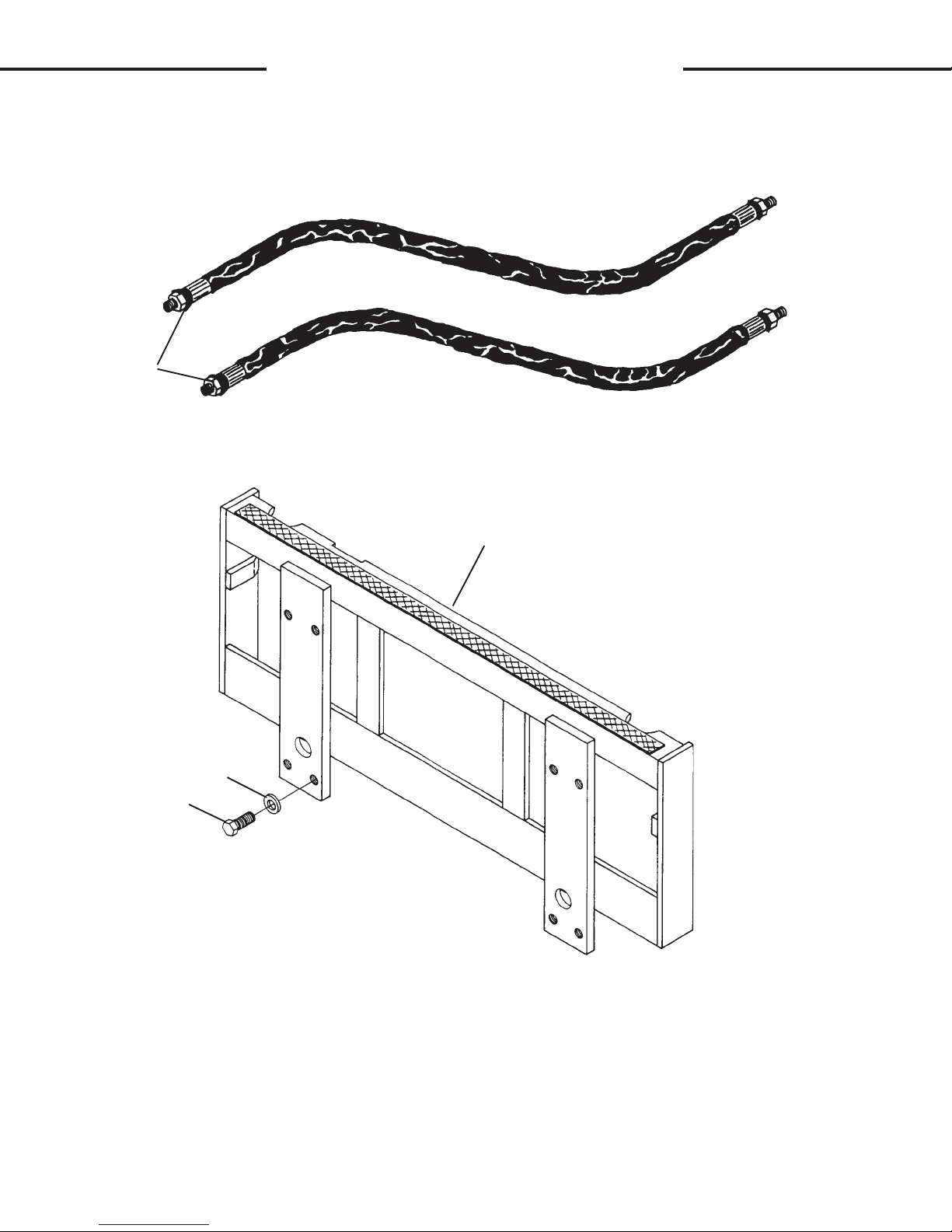
TRENCHER MOUNTING KIT #79106
NO REQ'D PART NO. DESCRIPTION
1 2 37449 Hose Assembly, .62" x 112"
(SAE 100R2-2Wire) 12MP-10MB-HS
2 1 78046 Trencher Attaching Bracket
3 8 1866 .75" UNC x 2.25" Socket Head Capscrew
4 8 1649 .75" Hard Flat Washer
5 8 1231 .75" UNC Hex Nut
5768
6-10-94-3

E
E
MOUNTING KIT INSTALLATION
TRENCHER MOUNTING KIT #79108
1
2
3
4
5
5769
2-13-92

E
E
MOUNTING KIT INSTALLATION
TRENCHER MOUNTING KIT #79108
NO REQ'D PART NO. DESCRIPTION
1 2 37366 Hose Assembly, .50" x 112"
(SAE 100R2-2Wire) 8MP-10MB-HS
2 1 78046 Trencher Attaching Bracket
3 8 1866 .75" UNC x 2.25" Socket Head Capscrew
4 8 1649 .75" Hard Flat Washer
5 8 1231 .75" UNC Hex Nut
5770
6-10-94-2
E
E
MOUNTING KIT INSTALLATION
TRENCHER MOUNTING KIT #79110
1
2
3
5
4
5771
2-13-92

E
E
MOUNTING KIT INSTALLATION
TRENCHER MOUNTING KIT #79110
NO REQ'D PART NO. DESCRIPTION
1 2 35792 Hose Assembly, .62" x 82"
(SAE 100R2-2Wire) 8MP-10MB-HS
2 1 78232 Trencher Attaching Bracket
3 8 1140 .75" UNC x 2.25" Hex Capscrew
4 8 1649 .75" Hard Flat Washer
5 8 1231 .75" UNC Hex Nut
5772
2-13-92
E
E
MOUNTING KIT INSTALLATION
TRENCHER MOUNTING KIT #79111
1
2
3
4
5
6
5773
6-10-94-2

MOUNTING KIT INSTALLATION
TRENCHER MOUNTING KIT #79111
NO REQ'D PART NO. DESCRIPTION
1 2 35792 Hose Assembly, .62" x 82"
(SAE 100R2-2Wire) 8MP-10MB-HS
2 1 78247 Right Trencher Mount
3 1 78248 Left Trencher Mount
4 8 1140 .75" UNC x 2.25" Hex Capscrew
5 8 1649 .75" Hard Flat Washer
6 8 1231 .75" UNC Hex Nut
EE
5774
6-10-94-2

EE
MOUNTING KIT INSTALLATION
TRENCHER MOUNTING KIT #79112
1
2
3
5
6
4
5775
6-13-94-2

E
E
MOUNTING KIT INSTALLATION
TRENCHER MOUNTING KIT #79112
NO REQ'D PART NO. DESCRIPTION
1 2 37367 Hose Assembly, .62" x 97"
(SAE 100R2-2Wire) 8MP-10MB-HS
2 1 78252 Right Trencher Mount
3 1 78253 Left Trencher Mount
4 8 1140 .75" UNC x 2.25" Hex Capscrew
5 8 1649 .75" Hard Flat Washer
6 8 1231 .75" UNC Hex Nut
5776
6-13-94-2
E
E
MOUNTING KIT INSTALLATION
TRENCHER MOUNTING KIT #79240
1
2
4
3
5850
4-7-92

E
E
MOUNTING KIT INSTALLATION
TRENCHER MOUNTING KIT #79240
NO REQ'D PART NO. DESCRIPTION
1 2 35792 Hose Assembly .62" x 82"
(SAE 100R2-2Wire) 8MP-10MB-HS
2 1 69701 Trencher Attaching Bracket
3 8 1137 .75" UNC X 1.50" Hex Capscrew
4 8 1649 .75" Hard Flat Washer
5851
4-7-92

EE
MOUNTING KIT INSTALLATION
TRENCHER MOUNTING KIT #79311
1
2
3
4
5
6
5852
6-13-94-2

E
E
MOUNTING KIT INSTALLATION
TRENCHER MOUNTING KIT #79311
NO REQ'D PART NO. DESCRIPTION
1 2 35792 Hose Assembly .62" x 82"
(SAE 100R2-2Wire) 8MP-10MB-HS
2 1 67050 Right Trencher Mount
3 1 67049 Left Trencher Mount
4 8 1140 .75" UNC X 2.25" Hex Capscrew
5 8 1649 .75" Hard Flat Washer
6 8 1231 .75" Hex Nut
5853
6-13-94-2

E
E
MOUNTING KIT INSTALLATION
TRENCHER MOUNTING KIT #79314
1
2
3
4
5
5854
4-7-92

E
E
MOUNTING KIT INSTALLATION
TRENCHER MOUNTING KIT #79314
NO REQ'D PART NO. DESCRIPTION
1 2 35792 Hose Assembly .62" x 82"
(SAE 100R2-2Wire) 8MP-10MB-HS
2 1 78226 Trencher Attaching Bracket
3 8 1866 .75" UNC X 2.25" Socket Head Capscrew
4 8 1649 .75" Hard Flat Washer
5 8 1231 .75" Hex Nut
5855
6-13-94-2

E
E
MOUNTING KIT INSTALLATION
617 TRENCHER
GENERAL INFORMATION
A mounting kit is required to attach the trencher to the skid steer.
Your trencher may have been shipped with the mounting kit installed. The
following instructions are provided here to help you install the mounting kit
in the case that yours was not installed at the factory.
This manual contains a diagram and parts list of the mounting kits
located in the front of this section. To determine which mounting kit you
need for your skid steer, refer to the chart in Section D. Study the diagram
and familiarize yourself with the names of the various parts. This knowledge will assist you in understanding these instructions. Read the complete
mounting instructions that follow before you begin. Read all safety warnings before operating the trencher.
In addition to the complete trencher assembly which includes the
mounting and hydraulic kit, you will also need a pair of couplers (one male
and one female) to hook-up the hydraulic hoses. The couplers must fit the
male hydraulic hose ends. The couplers must also mate up to the skid
steer's auxiliary hydraulic system couplers. You should be able to purchase
such couplers from your skid steer dealer.
MOUNTING INSTRUCTIONS
1. Remove all shipping banding from the trencher and attaching
bracket(s). Remove any other mounting kit components from their
packaging.
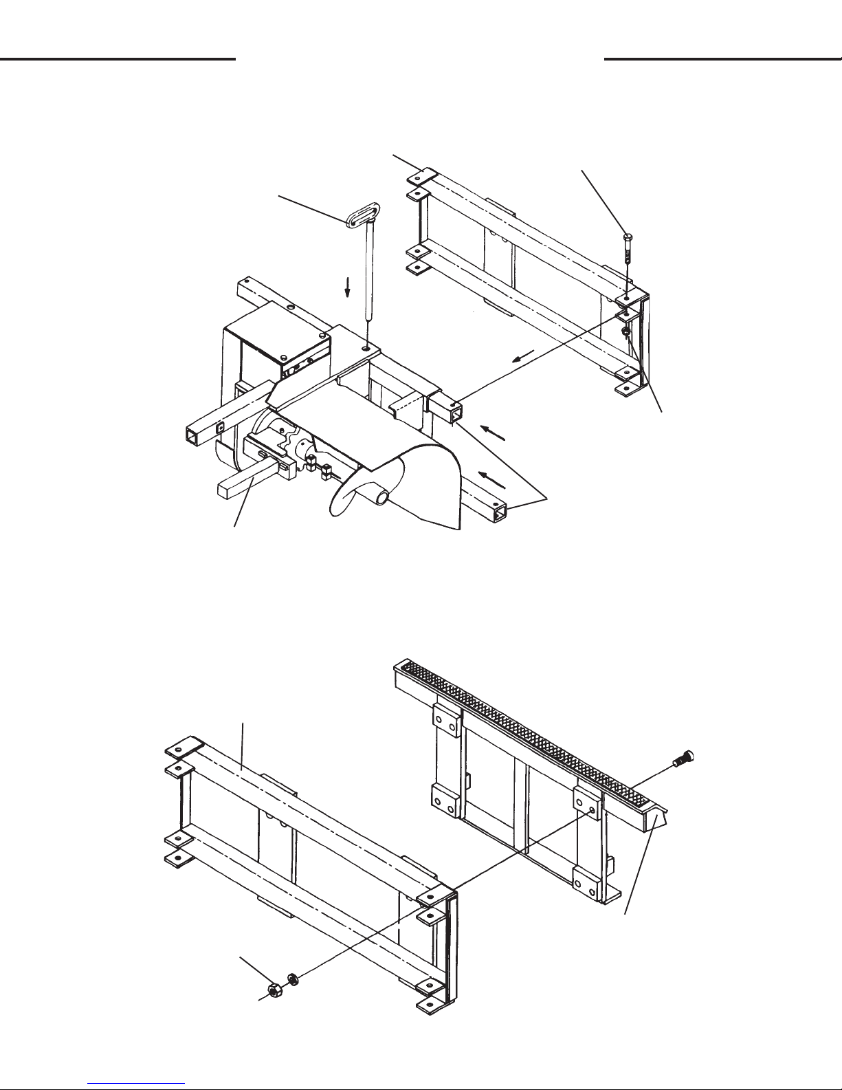
2 . NOTE: The side shift mounting frame may have been shipped already
installed. In the event yours was not installed -attach the side shift
mounting frame to the trencher by sliding the two side shift inner
tubes (part #78824) through the trencher mount lining up one set of
side shift holes and installing the lock pin (part #79113). Attach the
side shift mounting frame to the side shift inner tubes using the four
.75"UNC x 4.50" capscrews and lock nuts provided. (See Figure #1)
5777
2-21-92
E
E
MOUNTING KIT INSTALLATION
617 TRENCHER
FIGURE #1
SIDE SHIFT MOUNTING FRAME
LOCK PIN
BASIC TRENCHER ASSEMBLY
.75"UNC X 4.50 CAPSCREW
.75"UNC LOCK NUT
SIDE SHIFT INNER TUBES
3. Mount the attaching bracket(s) to the side shift mounting frame on the tren-
cher using the .75" hardware provided. Use the mounting kit assembly
diagram and parts list at the front on this section as a reference for the
correct hardware needed. (See Figure #2)
FIGURE #2
SIDE SHIFT MOUNTING FRAME
ATTACHING BRACKET
.75" HARDWARE
5778
2-21-92

E
E
MOUNTING KIT INSTALLATION
617 TRENCHER
4. Attach the two hydraulic hoses supplied in the kit to the trencher as shown in
Figure #3.
5. Attach the appropriate couplers to their corresponding hydraulic hoses. See
your skid steer owner's manual for proper identification of auxiliary hydraulic
coupler flow. Flow through the hydraulic hoses is noted in Figure #3.
FIGURE #3
HYDRAULIC MOTOR
TRENCHER
POWER TO TRENCHER
RETURN FROM TRENCHER
5779
2-21-92

F
F
TRENCHER INSTALLATION
617 TRENCHER
GENERAL INFORMATION
The following instructions will help you to mount your trencher on your skid
steer. The trencher uses the skid steer's quick-change attaching system for ease
on installation. Therefore, if you know how to attach the skid steer loader bucket,
attaching the trencher should prove no problem.
You must install the mounting kit prior to installing the trencher. If you have
not installed the mounting kit, turn to Section E and do it now. Remember to read all
safety warnings, decals, and operating instructions before operating the skid steer
or trencher.
MOUNTING INSTRUCTIONS
1. If you haven't done so already, remove the steel shipping banding from
around the trencher and skid.
2. Set the quick-change attaching lock on the skid steer toolbar to the unlocked
position. Lower the skid steer loader arms and tilt the toolbar down low
enough to pass under the top lip of the mounting kit adaptor plate.
3. Following all standard safety practices, start the skid steer and slowly drive it
in back of the trencher. Position the skid steer so that the top of the toolbar
is in under the lip on the adaptor plate. (See Figure #1)
FIGURE #1
SKID STEER
ADAPTOR PLATE
TRENCHER
DRIVE FORWARD
TOOLBAR
5780
2-21-92

F
F
TRENCHER INSTALLATION
617 TRENCHER
4. Tilt the toolbar back to hook the trencher onto the toolbar. It may be neces-
sary to lift the loader arm somewhat.
5. Set the quick-change attaching lock to the locked position to secure the
trencher. It may be necessary to raise, lower, or tilt the toolbar in order for the
trencher mount and toolbar to properly align so the locking mechanism can
be activated.
6. With the auxiliary hydraulic system turned off, route the trencher hydraulic
hoses over the top of the mount and toolbar and connect to their proper
auxiliary couplers.
7. Complete the predelivery check list located in the back of this manual (Sec-
tion R). Trencher installation is now complete.
5781
2-21-92

G
G
OPERATING INSTRUCTIONS
CONTROLS
617 TRENCHER
GENERAL INFORMATION
Simplicity of operation is one of the key features of the 617 trencher. The
trenchers themselves have no controls, just a few adjustments to check. It is important however, to be familiar with, and know the controls and adjustments on both the
trencher and the skid steer. Such knowledge is crucial for safe, efficient operation
of equipment. Take the time to learn how they operate now.
SKID STEER
Your trencher mounts to the toolbar / attachment plate of the skid steer. Due
to this arrangement, thorough knowledge of the skid steer controls is necessary for
trencher operation. Read your skid steer owner's manual for information regarding
skid steer operation before attempting to use the trencher.
RAISING / LOWERING THE TRENCHER
Raise / lower the trencher unit by raising / lowering the skid steer loader arms
through their appropriate skid steer controls. (See Figure #1)
CAUTION! Become aware of any overhead power or telephone lines, tree
limbs, etc., that the raised trencher could come into contact
with. Contact with electrical lines could cause serious injury or
death.
FIGURE #1
RAISE
SKID STEER
LOADER ARM
TRENCHER
LOWER
5782
2-23-92

G
G
OPERATING INSTRUCTIONS
CONTROLS
617 TRENCHER
TILTING THE TRENCHER
Tilt the trencher unit up or down by tilting the toolbar / attachment plate back
or forward through its skid steer control. We recommend a 60° digging angle for
general trenching as measured from ground level (the horizon). (See Figure #2)
SIDE SHIFTING THE TRENCHER
FIGURE #2
SKID STEER LOADER ARM
UP
TOOLBAR / ATTACHMENT
PLATE
(LOCATED INSIDE ADAPTOR)
DOWN
Your trencher has an adjustment to shift the whole unit to the side on its own
mount. To shift the unit sideways, first remove the locking pin from the back of the
unit.
Lower trencher until trencher frame is resting on the ground, then counterrotate the tires so that the skid steer moves in a sideways motion. Continue moving
until side shift holes are aligned and replace locking pin.
IMPORTANT: Always reinstall the locking pin to prevent the trencher from
shifting sideways during operation.
NOTE: Slight shifting of the trencher from side to side may be necessary to
align the side shift holes for reinstalling the locking pin.
5783
2-23-92

G
G
OPERATING INSTRUCTIONS
CONTROLS
617 TRENCHER
STARTING AND STOPPING THE TRENCHER
Power to the trencher is supplied by oil from the skid steer auxiliary hydraulic
system, which passes through the hydraulic hoses and into the trencher's hydraulic
motor.
The trencher unit itself does not have an on/off control but is operated by the
skid steer auxiliary hydraulic control mechanism. The start the trencher, engage the
auxiliary hydraulics. (This is usually done by a pedal located in the middle of the
skid steer floor. See your skid steer owner's manual.) To stop the trencher, disengage the auxiliary hydraulics.
TRENCHER SPEED CONTROL
Again it may be noted that power to the trencher is supplied by the skid
steer's auxiliary hydraulics. Trencher speed and power are determined by the flow
of oil coming out of the auxiliary system, which in turn is dependent upon skid steer
engine speed. To increase trencher speed, increase skid steer engine speed, to
decrease trencher speed, decrease skid steer engine speed.
When first starting a trench throttle down the skid steer engine to half throttle.
This will reduce the shock to the skid steer and trencher when the digging teeth first
contact the ground. Once the trench is started, set the engine back to full throttle.
For general use operate the trencher with the skid steer engine at full throttle
to provide maximum power to the auxiliary hydraulics and thus the trencher.
AUGER HEIGHT
The auger is fixed to the trencher mainframe and has no separate adjustment. To raise the auger, raise the trencher as previously described. This will raise
the auger and thus leave the dirt or spoil closer to the trench.
Lowering the trencher will cause the auger to lower, moving the spoil away
from the trench. The built-in skid shoe on the 617 trencher will prevent the auger
from being lowered to the extent that the auger itself starts to dig in the ground as
this will greatly reduce efficiency.
5784
2-23-92

G
G
OPERATING INSTRUCTIONS
CONTROLS
617 TRENCHER
It should be noted that raising or lowering the trencher to change the auger
height will also change the trenching depth. You will need to compensate for this by
changing the tilt of the trencher down or up accordingly. (See Figure #3)
FIGURE #3
TRENCHER
AUGER
AUGER
SPOIL
SPOIL
CRUMBER SHOE/BAR ADJUSTMENT
The purpose of the crumber shoe is to keep any loose dirt in the trench close
enough to the digging chain so that the digging teeth can grab it and remove it. This
will give you a cleaner finished trench. Your trencher has an adjustable crumber bar
that can be lengthened or shortened to bring the crumber shoe closer or farther from
the digging chain.
To adjust the crumber bar length, loosen the two jam nuts found at the end of
the mainframe crumber bar tube. Slide the bar in or out to achieve the desired
spacing (we suggest a distance of about 4" between crumber shoe and digging
teeth for best overall results). Tighten the set screws and jam nuts when finished.
(See Figure #4 on the next page)
5785
2-23-92

G
G
OPERATING INSTRUCTIONS
CONTROLS
617 TRENCHER
FIGURE #4
MAINFRAME CRUMBER
BAR TUBE
SET SCREW
CRUMBER BAR
JAM NUT
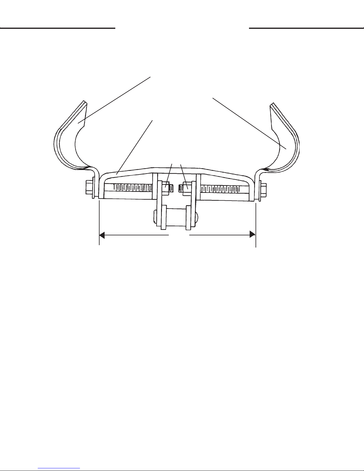
CHAIN TENSION ADJUSTMENT
When trenching, the digging chain tension should be adjusted so that
the chain is as loose as possible, without jumping off the sprocket or idler
wheel. To do this, an adjustment is provided on the digging boom.
These booms have an adjusting bolt on each side at the trencher end
of the boom. The head of the bolts are kept from rotating by special tubes
welded onto the mainframe. The end of the bolt rests in a tube welded to
the boom. Each bolt has a jam nut and a .75" hex nut on it. To tighten the
chain, "back off" the jam nut from the regular nuts. Now turn the standard
nuts off the adjusting bolts. This will push the boom out and thus tighten
the chain. Retighten the jam nut when finished. To loosen the chain, follow the same procedure, except turn the hex nut onto the adjusting bolt.
(See Figure #5)
ADJUSTING BOLTS
FIGURE #5
TRENCHER
MAINFRAME
.75" JAM NUT
.75" HEX NUT
DIGGING BOOM
5786
2-23-92
G
G
OPERATING INSTRUCTIONS
CONTROLS
617 TRENCHER
This procedure must be done simultaneously to both adjusting bolts to
prevent the boom from becoming wedged onto its mount.
CAUTION! Never work on, or make adjustments to any part of the tren-
cher while the unit is running. You could get caught in the
digging teeth which could cause severe injury or death.
It is common for your trencher to need its digging chain tightened
after the first 10 to 20 minutes of operation as the chain and sprocket seat
themselves.
5787
2-23-92
G
G
OPERATING INSTRUCTIONS
OPERATING TECHNIQUES
SKID STEER TRENCHERS
GENERAL INFORMATION
The design of your trencher makes it relatively simple to use. With
the help of the information in this section and a little practice you should
become proficient in it's operation in no time. Observe the following points
to obtain the best results with the least amount of wear on the machine.
Read the "Safety Precautions" section of this manual before you begin.
(See Section B)
CAUTION! Operate the trencher only when seated at the skid steer con-
trols.
Do not operate the skid steer without proper ROPS (Roll-Over-
Protective-Structure), seat belt, and hard hat.
Pay attention to the job at hand. Be alert to the possibilities of
others in the work area.
Never let anyone work around, or perform maintenance on the
trencher while it is running.
Always use a crumber assembly on the trencher.
BEFORE YOU START TRENCHING
Before any excavating is started, it is always a good idea to plan out
the job first. Various things need to be considered and taken into account
prior to the actual trenching. The operator should inspect the job site and
take notice on any potential hazards in the area. He should have a complete
understanding of the task he is expected to perform. Figure out what will
be done with the spoil (excavated soil), will it be used to backfill or be
trucked out? What are the soil conditions like? Will you have to work
around others? Etc.
WARNING! Check the prospective trenching area for hidden utility lines
before operating the trencher. Contacting a utility line with the
trencher could cause electrocution resulting in death. Call all
utility companies and have them plot out all their lines first. If
you damage a utility line, shut off the equipment at once and
contact the affected utility immediately.
Once you have become familiar with the job site and understand the
job requirements it is time to set up for the actual trenching. Check the soil
type (hard, soft, rocky, etc.) and the trenching requirements (how deep,
wide, etc.). Install the proper digging chain, sprocket, boom, crumber bar
and shoe for the job at hand. Information on chains, sprockets, booms,
crumber bars and shoes may be found in Sections I and J.
5788
2-26-92

G
G
OPERATING INSTRUCTIONS
OPERATING TECHNIQUES
SKID STEER TRENCHERS
Locate the trencher on the mount with the side shift mechanism (as
explained earlier in this section) where it will be most efficient and easy to
use.
Mark off the area to be trenched out. This can be done with powdered lime, chalk, or a guide string and stakes. Block off the area from all
bystanders if possible.
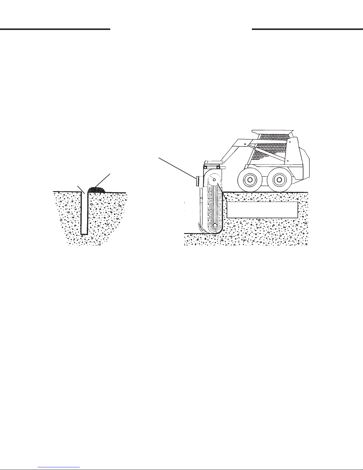
STARTING THE TRENCH
Position the skid steer with the trencher boom directly over the center
of the trench layout. It will take about 4' of trenching before the trencher
will be able to operate at the desired level, so plan for this and position the
trencher about 4' behind where you want the actual trench to start.
NOTE: The skid steer is driven in
trench driving the skid steer forward.
Raise the trencher with the skid steer loader arms and tilt the trencher
at a 45° angle. (See Figure #6) Position the unit so that the digging teeth
are just above ground level.
Set the skid steer throttle at half speed. Start the digging chain by
engaging the skid steer auxiliary hydraulic system.
FIGURE #6
TILT DOWN 45°
TRENCHER
reverse when trenching. You cannot
TOOLBAR
RAISE
LOADER ARM
SKID STEER
5789
2-26-92

G
OPERATING INSTRUCTIONS
OPERATING TECHNIQUES
SKID STEER TRENCHERS
CAUTION! When lowering a moving digging chain to the ground the force
of the teeth grabbing the ground will try to pull the trencher
suddenly forward.
steer set to help counteract the force.
Slowly lower the digging chain into the ground to start the trench.
Do this by lowering the trencher with the loader arms. Continue lowering
the unit until the crumber end rolls all the bay back on the crumber bar
(See Figure #7)
IMPORTANT: After the crumber end has rolled all the way back, do not
lower the trencher any farther without moving the skid steer in reverse.
Failure to do so could result in bending of the crumber boom, which is
covered by warranty.
Be prepared. Have the brake on the skid
not
G
FIGURE #7
CRUMBER BOOM
CRUMBER END
Once the crumber end has "bottomed out", begin slowly creeping the
skid steer in
ing the required depth, stop lowering and tilt the trencher to a 60° to 65°
angle. A 60° - 65° angle works best for general trenching. (See Figure #8)
reverse while continuing to lower the loader arms. When near-
LOADER ARM
LOWER
WARNING! Be alert to what is happening around you. Look behind you
before reversing the skid steer to trench. Be aware of any
person or thing in the path of the skid steer. Observe any
terrain changes such as drop-offs or soft ground.
5790
2-26-92

G
G
OPERATING INSTRUCTIONS
OPERATING TECHNIQUES
SKID STEER TRENCHERS
FIGURE #8
CREEP IN REVERSE
LOWER
When trenching, remember to keep in mind the spoil placement.
Position the trencher so that the auger floats at ground level to move spoil
away from the trench. (See Figure #9)
FIGURE #9
NOTE DIGGING ANGLE
TRENCH
SPOIL PILE
AUGER AT
GROUND LEVEL
5791
2-26-92
G
G
OPERATING INSTRUCTIONS
OPERATING TECHNIQUES
SKID STEER TRENCHERS
Raise the trencher so that the auger rides above the ground level to
leave the spoil beside the trench. The higher the auger, the closer to the
trench the spoil will be placed. You may find that it generally takes less
power to run the digging chain if the auger runs 3" - 6" (inches) off the
ground, and thus increasing the potential footage of trench produced per
hour. The higher you want the auger, the more vertical you will have to tilt
the trencher to achieve the same trench depth. (See Figure #10)
FIGURE #10
TRENCH
With the desired trench depth reached, advance the skid steer throttle
to the desired engine RPM (we suggest full throttle for maximum digging
power). Continue creeping the skid steer in reverse. Monitor the skid steer
hydraulic oil pressure and temperature gauges as you trench. If hydraulic
oil temperature or pressure gets too high, reduce skid steer creeping speed
to reduce the load on the auxiliary hydraulic system.
INCREASED DIGGING ANGLE TO
ACHIEVE THE SAME TRENCH DEPTH
WITH AUGER RAISED AS IN FIGURE #9
SPOIL PILE
AUGER RAISED ABOVE
GROUND LEVEL
IMPORTANT: Trying to trench at a speed faster than the auxiliary hydraulic
system can handle could cause the trencher to stall. Continued stalling in a
short period of time can cause excessive oil temperature which can lead to
pump failure. Do not try to trench too much too quickly. If oil temperature
becomes too hot, stop the trencher and allow the oil to cool.
STALLING THE TRENCHER
If the trencher stalls while digging, move the skid steer forward
slightly to free the trencher. You may be able to free up the digging chain
by changing its direction of travel with the auxiliary hydraulic controls.
Repeated stalling of the trencher will cause oil to overheat rapidly and
should be avoided.
5792
2-26-92

G
G
OPERATING INSTRUCTIONS
OPERATING TECHNIQUES
SKID STEER TRENCHERS
TURNING WHILE TRENCHING
Gradual turns can be made while trenching. However, the tightness
of the turn is directly proportional to the angle and length of the boom. In
other words the greater the angle of the trencher boom to the ground level,
the sharper the turn that can be trenched. (See Figures #11 & #12) Also
the shorter the boom length the sharper the possible turn. Remember, the
greater the increase in boom angle the higher the unit will have to be raised
out of the trench to keep a unified trench depth. Shallow boom angles will
severely limit turning ability.
IMPORTANT: Turning too tightly while trenching will cause the trencher to
jam in the trench and stall, leading to excessive oil temperatures. Turning
too tightly can also cause the trencher boom to bend. Take it easy when
turning. Proceed slowly with caution.
FIGURE #11
FIGURE #12
TURNING WITH THE BOOM
AT A 90° DIGGING ANGLE
TOP VIEW
TURNING WITH THE BOOM AT
A 60° DIGGING ANGLE
TOP VIEW
5793
2-26-92

G
G
OPERATING INSTRUCTIONS
OPERATING TECHNIQUES
SKID STEER TRENCHERS
MAKING SHARP TURNS
To make sharp turns and 90° angles you will have to dig two
trenches. Dig the first trench as you normally would. Then reposition the
unit and dig the second trench at the appropriate angle. Be sure to take
into account the extra lead-in space needed for the trencher to get down to
the desired trench depth. (See Figure #13)
FIGURE #13
TOP VIEW
2nd TRENCH
1st TRENCH
LEAD-IN
RECOMMENDED DIGGING ANGLES
A 90° digging angle is recommended for use in rock and frost conditions, and when trenching sharp corners. The 90° angle reduces excessive
side pressure on the boom and digging chain when trenching corners. (See
Figure #14)
A 60° - 65° digging angle is recommended for normal trenching. At
this angle there will be less carry-over, and a cleaner trench bottom can be
maintained than at a 90° angle. (See Figure #14)
FIGURE #14
90° DIGGING
ANGLE
GROUND LEVEL /
HORIZON
65° DIGGING
ANGLE
5794
2-26-92

GG
OPERATING INSTRUCTIONS
OPERATING TECHNIQUES
SKID STEER TRENCHERS
TRENCHING WITHOUT THE CRUMBER ASSEMBLY
WARNING! The crumber bar and crumber shoe assembly are there for a
reason, YOUR SAFETY! There are a few instances where
removal may be necessary however. In these cases operate
with extreme caution. Reinstall the crumber bar and crumber
shoe as soon as possible.
You can use your trencher to dig under obstacles such as sidewalks.
To do so, remove the crumber shoe and bar assembly and start your trench
as before within a foot of the sidewalk. With the crumber bar and shoe
removed you can start the trench vertically without any lead-in space.
When the desired depth has been reached, tilt the trencher at a 60°
angle while digging, then creep the skid steer
sidewalk. Be careful not to contact the edge of the sidewalk with the digging teeth.
forward and trench under the
After you have gone as far as you can without contacting the sidewalk, drive the skid steer in reverse to clear the sidewalk and remove the
trencher from the trench. Line up the unit on the other side of the walk and
continue to trench as described above until the two trenches are connected.
(See Figure #15)
FIGURE #15
CREEP FORWARD
CRUMBER BAR AND SHOE
ASSEMBLY REMOVED. REPLACE
AS SOON AS POSSIBLE
SIDEWALK
1st TRENCH
2nd TRENCH
AVOID CONTACTING SIDEWALK
Reinstall the crumber bar and crumber shoe assembly immediately.
Some spoil will be left in the trench since the crumber was removed during
the operation.
5795
2-26-92

GG
OPERATING INSTRUCTIONS
OPERATING TECHNIQUES
SKID STEER TRENCHERS
ENDING A TRENCH
When you have dug your trench, remember that the trencher boom is
at an angle, and that you must continue trenching until the end of the boom
has dug past the proposed end of the trench. Once the end of the trench
has been dug, keep the trencher running and lift the skid steer loader arms
to lift the unit clear of the trench. When the trencher has cleared the
trench, disengage the auxiliary hydraulics to stop the trencher. Drive the
skid steer away from the trench.
TRANSPORTING THE TRENCHER
When transporting the trencher, remember to keep the trencher as
low to the ground as is practical. The lower the trencher rides, the more
stable the skid steer will be. You do not want the trencher so low that the
digging teeth touch the ground in rough terrain. Shut off the trencher before moving it away from the trench. Never transport the trencher around
the job site or anywhere else while the digging chain is moving.
TRENCHER PERFORMANCE
Remember that your trencher's performance is directly related to the
power available at you skid steer's auxiliary hydraulic system. If the trencher seems to lack power or speed, it may be due to your skid steer's lack
of sufficient auxiliary power.
Trencher performance is also related to how well it's maintained,
digging tooth wear, and type and size of digging chain, crumber boom and
shoe used. For more information on proper maintenance and chain wear
see Section L. For information on chain, sprocket, boom, and crumber
options see Sections I and J. If problems arise see "Trouble Shooting"
Section N.
5796
2-26-92

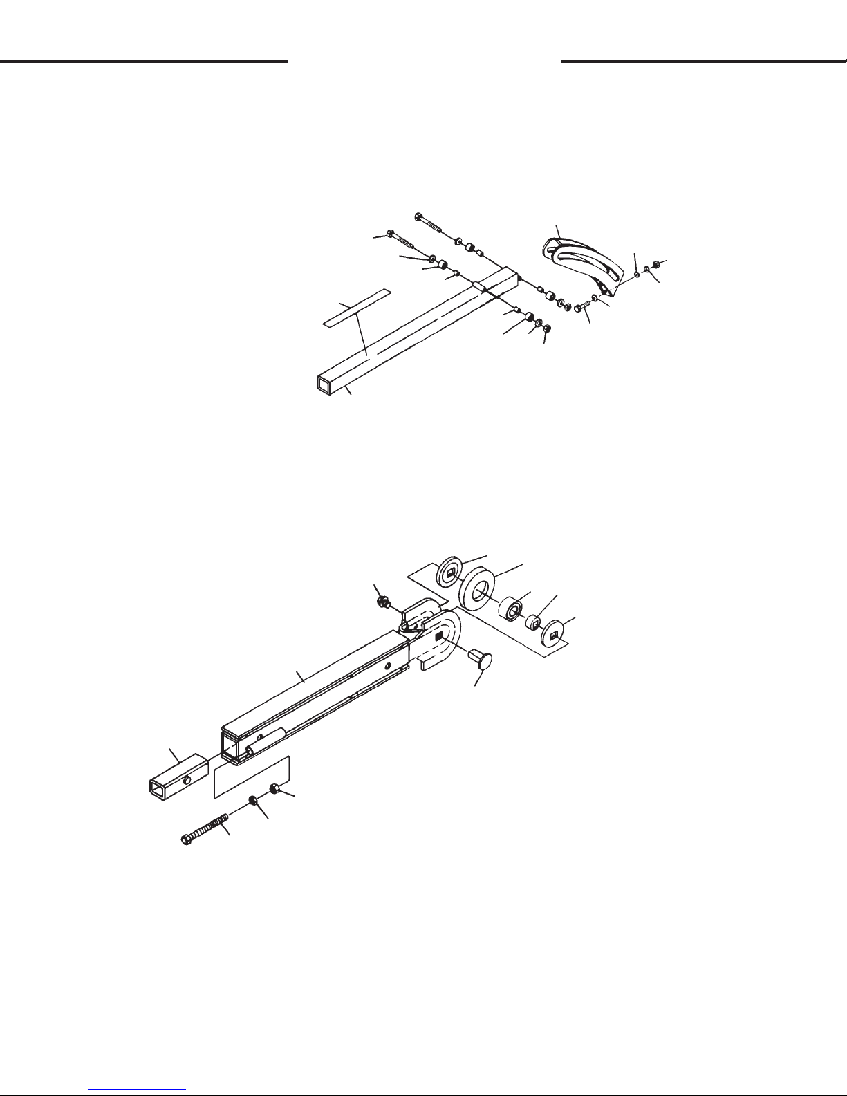
II
TRENCHER ASSEMBLY
617 TRENCHER
ASSEMBLY #78820
5753
3-4-92

I
I
TRENCHER ASSEMBLY
617 TRENCHER
ASSEMBLY 78820
NO REQ'D PART NO. DESCRIPTION
1 1 79113 Lock Pin
2 1 78806 Side Shift Mounting Frame
3 4 1148 .75" UNC x 4.50" Hex Capscrew
4 4 1534 .75" UNC Lock Nut
5 2 78824 Side Shift Inner Tube
6 4 1021 .31" UNC x .75" Hex Capscrew
7 4 1502 .31" Lock Washer
8 4 1513 .31" Flat Washer
9 1 78840 Chain Guard
10 1 1364 .62" UNF x 1.50" Hex Capscrew
11 1 1506 .62" Lock Washer
12 1 1517 .62" Flat Washer
13 1 78823 Sleeve Spacer
14 1 78821 Driver Sprocket
15 1 67799 Key (.312" x .275" x 1.25")
16 4 1091 .50" UNC x 1.75" Hex Capscrew
2 1092 .50" UNC x 2.00" Hex Capscrew
17 2 78844 Adjusting Bolt
18 1 78838 Motor Mounting Plate
19 1 72333 Hydraulic Motor
20 8 1505 .50" Lock Washer
21 8 1228 .50" UNC Hex Nut
22 4 1516 .50" Flat Washer
23 1 78769 Mainframe
24 1 78837 Drive Chain (#80 - 52 Pitches)
25 1 53298 Connecting Link
26 2 1769 .50"UNC x 1.00" Sq. Head Setscrew
27 2 1242 .50" UNC Jam Nut
28 1 1651 Snap Ring
29 Varies 6622 Thrust Washer
30 1 78822 Driven Sprocket
31 3 1572 .50"-13UNC x .50" Set Screw
32 1 53744 Key (.50" x .50" x 2.00")
33 1 78809 Headshaft Spacer
34 1 1681 Snap Ring
35 1 78841 Bearing
36 1 6616 Grease Zerk
37 1 8085 Bearing
38 1 1601 Snap Ring
39 1 78833 Dirt Guard
40 1 78808 Headshaft
41 1 53742 Key (.38" x .38" x 3.00")
42 1 78832 Sprocket
43 2 1095 .50" UNC x 2.75" Hex Capscrew
44 1 78828 Auger
5754
1-18-94-2
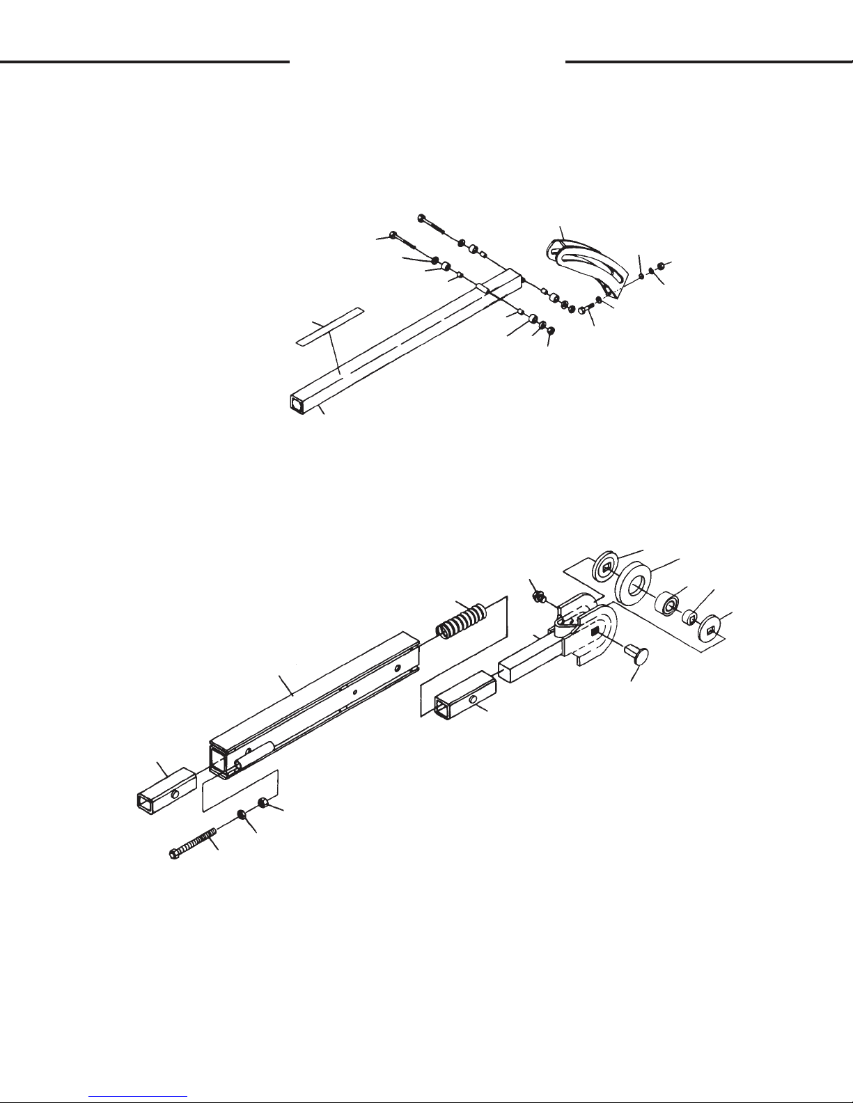
II
TRENCHER ASSEMBLY
30" BOOM AND CRUMBER
ASSEMBLY #79117
6
14
15
1
2
3
4
4
3
2
5
9
2
7
8
2
16
20
21
17
22
19
18
10
11
12
13
10
6911
4-17-96

I
I
TRENCHER ASSEMBLY
30" BOOM AND CRUMBER
ASSEMBLY #79117
NO REQ'D PART NO. DESCRIPTION
1 2 1054 .38" UNC x 3.75" Hex Capscrew
2 8 1514 .38" Flat Washer
3 4 53038 Crumber Roller
4 4 53039 Crumber Roller Bushing
5 2 1536 .38" UNC Nylock Nut
6 1 53087 Crumber End
7 2 1226 .38" UNC Hex Nut
8 2 1503 .38" Lock Washer
9 2 1044 .38" UNC x 1.25" Hex Capscrew
10 2 54067* Idler Spacer
11 1 79103* Idler Wheel
12 1 8085* Idler Bearing
13 1 53988* Idler Bearing Hub
14 2 40161 Decal - Stand Clear
15 1 53070 30" Crumber Bar / Personal Restraint Bar
16 1 53138 Boom Bushing
17 1 80087 30" Boom
18 1 53132 1.12" Square Pin
19 1 1548 .75" UNC x 1.25" Nylock Capscrew
20 2 62702 Adjusting Bolt
21 2 1245 .75" UNC Jam Nut
22 2 1231 .75" UNC Nut
NOTE: Idler Roller Assembly Repair Kit #80868 includes all parts marked
with an asterisk (*).
6912
4-17-96
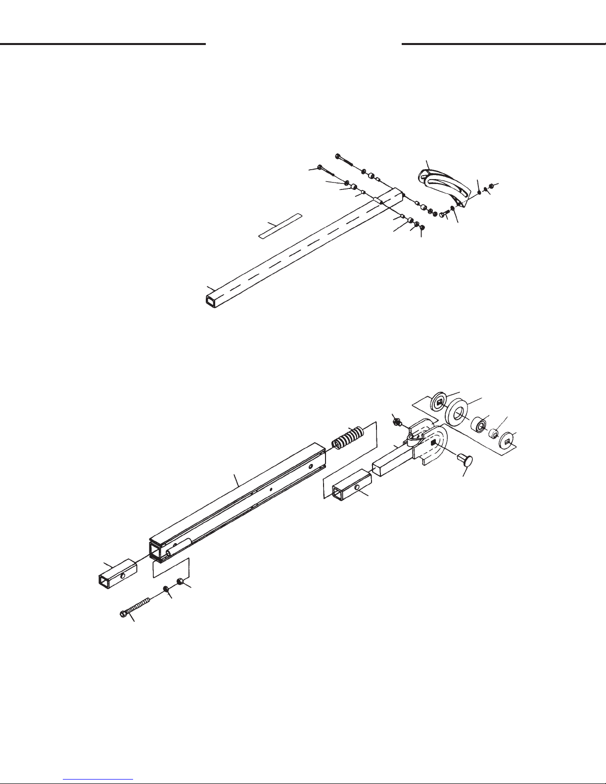
II
TRENCHER ASSEMBLY
36" BOOM AND CRUMBER
ASSEMBLY #79083
6
14
15
1
2
3
4
4
3
2
5
9
2
7
8
2
16
22
23
17
24
18
16
21
20
19
10
11
12
13
10
5757
2-3-92

I
I
TRENCHER ASSEMBLY
36" BOOM AND CRUMBER
ASSEMBLY #79083
NO REQ'D PART NO. DESCRIPTION
1 2 1054 .38" UNC x 3.75" Hex Capscrew
2 8 1514 .38" Flat Washer
3 4 53038 Crumber Roller
4 4 53039 Crumber Roller Bushing
5 2 1536 .38" UNC Nylock Nut
6 1 53087 Crumber End
7 2 1226 .38" UNC Hex Nut
8 2 1503 .38" Lock Washer
9 2 1044 .38" UNC x 1.25" Hex Capscrew
10 2 54067* Idler Spacer
11 1 79103* Idler Wheel
12 1 8085* Idler Bearing
13 1 53988* Idler Bearing Hub
14 2 40161 Decal - Stand Clear
15 1 53069 36" Crumber Bar / Personal Restraint Bar
16 2 53138 Boom Bushing
17 1 79085 36" Boom
18 1 53188 Spring
19 1 53132 1.12" Square Pin
20 1 62717 Boom End
21 1 1548 .75" UNC x 1.25" Nylock Capscrew
22 2 62702 Adjusting Bolt
23 2 1245 .75" UNC Jam Nut
24 2 1231 .75" UNC Nut
NOTE: Idler Roller Assembly Repair Kit #80868 includes all parts marked
with an asterisk (*).
5758
4-17-96-4
II
TRENCHER ASSEMBLY
42" BOOM AND CRUMBER
ASSEMBLY #82113
6
15
14
1
2
3
4
4
3
2
5
2
7
8
9
2
16
22
23
24
17
18
16
21
20
19
10
11
12
13
10
6671
10-2-95

I
I
TRENCHER ASSEMBLY
42" BOOM AND CRUMBER
ASSEMBLY #82113
NO REQ'D PART NO. DESCRIPTION
1 2 1054 .38" UNC x 3.75" Hex Capscrew
2 8 1514 .38" Flat Washer
3 4 53038 Crumber Roller
4 4 53039 Crumber Roller Bushing
5 2 1536 .38" UNC Nylock Nut
6 1 53087 Crumber End
7 2 1226 .38" UNC Hex Nut
8 2 1503 .38" Lock Washer
9 2 1044 .38" UNC x 1.25" Hex Capscrew
10 2 54067* Idler Spacer
11 1 79103* Idler Wheel
12 1 8085* Idler Bearing
13 1 53988* Idler Bearing Hub
14 2 40161 Decal - Stand Clear
15 1 82125 42" Crumber Bar / Personal Restraint Bar
16 2 53138 Boom Bushing
17 1 82124 42" Boom
18 1 53188 Spring
19 1 53132 1.12" Square Pin
20 1 62717 Boom End
21 1 1548 .75" UNC x 1.25" Nylock Capscrew
22 2 62702 Adjusting Bolt
23 2 1245 .75" UNC Jam Nut
24 2 1231 .75" UNC Nut
NOTE: Idler Roller Assembly Repair Kit #80868 includes all parts marked
with an asterisk (*).
6672
10-2-95

I
I
TRENCHER ASSEMBLY
48" BOOM AND CRUMBER
ASSEMBLY #79084
6
15
14
1
2
3
4
4
3
2
5
2
7
8
9
2
16
22
23
24
17
18
16
21
20
19
10
11
12
13
10
5755
2-3-92

TRENCHER ASSEMBLY
48" BOOM AND CRUMBER
ASSEMBLY #79084
NO REQ'D PART NO. DESCRIPTION
1 2 1054 .38" UNC x 3.75" Hex Capscrew
2 8 1514 .38" Flat Washer
3 4 53038 Crumber Roller
4 4 53039 Crumber Roller Bushing
5 2 1536 .38" UNC Nylock Nut
6 1 53087 Crumber End
7 2 1226 .38" UNC Hex Nut
8 2 1503 .38" Lock Washer
9 2 1044 .38" UNC x 1.25" Hex Capscrew
10 2 54067* Idler Spacer
11 1 79103* Idler Wheel
12 1 8085* Idler Bearing
13 1 53988* Idler Bearing Hub
14 2 40161 Decal - Stand Clear
15 1 53068 48" Crumber Bar / Personal Restraint Bar
II
16 2 53138 Boom Bushing
17 1 79088 48" Boom
18 1 53188 Spring
19 1 53132 1.12" Square Pin
20 1 62717 Boom End
21 1 1548 .75" UNC x 1.25" Nylock Capscrew
22 2 62702 Adjusting Bolt
23 2 1245 .75" UNC Jam Nut
24 2 1231 .75" UNC Nut
NOTE: Idler Roller Assembly Repair Kit #80868 includes all parts marked
with an asterisk (*).
5756
4-17-96-4

COMBINATION ROCK AND FROST CHAIN
2.00" PITCH - TOOTH EVERY STATION
SERVICE PARTS
STATION #1 STATION #3STATION #2
11
2
15
14
10
4
13
1
15
10
3
12
10
STATION #4 STATION #5 STATION #6
4
15
STATION #7 STATION #8 STATION #9
13
11
11
13
12
10
16
13
10
2
1
16
6
11
14
11
14
3
15
10
5
10
STATION #10 STATION #11 STATION #12
4
14
10
15
18
15
3
8
10
11
14
10
17
10
4
7
10
9
14
17
3
19
9
6824
1-26-96

COMBINATION ROCK AND FROST CHAIN
2.00" PITCH - TOOTH EVERY STATION
SERVICE PARTS
NO PART NO. DESCRIPTION
1 83802 Carbide Bit Holder - 4" Right
2 83801 Carbide Bit Holder - 4" Left
3 54432 Cup Cutter - Right
4 54431 Cup Cutter - Left
5 83804 Carbide Bit Holder - 5" Right
(1) Weld Spot on Top for Identifying Purposes
6 83803 Carbide Bit Holder - 5" Left
(1) Weld Spot on Top for Identifying Purposes
7 83806 Carbide Bit Holder - 6" Right
(2) Weld Spots on Top for Identifying Purposes
8 83805 Carbide Bit Holder - 6" Left
(2) Weld Spots on Top for Identifying Purposes
9 83800 Spacer - 6" Cut
10 1692 .50" UNF Hex Nut
11 51547 Carbide Bit
12 83798 Tube Spacer
(Inside Mount Carbide Bit Holder)
13 54628 Tube Spacer
(Inside Mount Cup Cutter)
14 54440 Tube Spacer
(Outside Cup or Carbide Bit Holder)
15 1347 .50" UNF X 3.25" Hex Capscrew
16 1349 .50" UNF X 3.75" Hex Capscrew
17 1351 .50" UNF X 4.50" Hex Capscrew
18 1348 .50" UNF X 3.50" Hex Capscrew
19 1350 .50" UNF X 4.00" Hex Capscrew
NOTE: There are weld spots located on the top of the 5" and 6" Carbide
Bit Holders to assist in parts identification. One weld spot on the 5" Holders and two weld spots on the 6" Holders.
6825
1-26-96

J
DIGGING CHAIN OPTIONSDIGGING CHAIN OPTIONS
DIGGING CHAIN OPTIONS
DIGGING CHAIN OPTIONSDIGGING CHAIN OPTIONS
GENERAL INFORMATION
This section is devoted to digging chain options for your trencher. In
it you will find a listing of all the chain options available. You will also find
information on replacement parts, chain assembly, and chain conversion.
These options will increase the flexibility of your equipment, and make your
trenching job easier.
There is some basic information about the trencher and it's digging
components that you should know before you try to order any options. This
information is given here for your convenience. With it you will be able to
better understand the rest of this section.
CHAIN PITCH
J
The digging chains may be divided into groups by pitch. The pitch of
the chain is the distance between the centers of the holes in the chain links
(See Figure 1). The word pitch can also be used to describe the length of
the chain.
FIGURE #1 FIGURE #2
8 PITCH OF CHAIN
DISTANCE BETWEEN HOLE
CENTERS = PITCH
The 617 Trencher has a heavy weight chain with a tensil strength of
50,000 pounds and a pitch of 2.00".
There is one thing that you must understand about chain pitch. You
can not intermix components of different pitches. You cannot substitute
chain links of different pitches in a digging chain. Nor can you use a digging chain of one pitch, with a driver sprocket of a different pitch. Attempting to do so will cause the chain to "jump" off the sprocket continuously.
5802
10-10-00-2

J
DIGGING CHAIN OPTIONSDIGGING CHAIN OPTIONS
DIGGING CHAIN OPTIONS
DIGGING CHAIN OPTIONSDIGGING CHAIN OPTIONS
COMPONENT SIZE
The size of the digging component is based on the depth of the
trench it will dig with auger at ground level and a 60° boom digging angle
(See Figure 3). For example, a 36" boom is not necessarily 36" long. The
36" length means it will dig a trench 36" deep with the augers in their float
position and at a 60° digging angle.
FIGURE #3
J
36" BOOM
60°
BOOM DIGGING ANGLE
DIGGING STATIONS
Digging chains are made up of a series of individual links pinned
together. Every link has a special "Digging Station" link. These links are
designed so that the digging teeth can be attached to the basic chains (See
Figure 4). Digging chains may be purchased in any length, with or without
teeth. All chains, teeth, spacers and assorted digging hardware may be
purchased separately.
FIGURE #4
MOUNTING HARDWARE
DIGGING TOOTH
AUGER AT GROUND LEVEL
36"
DIGING STATIONS
This completes the basic information on digging chain options. The
rest of this section contains specific information on digging chains and parts
available, complete with part numbers. Again it may be noted that these
options are designed to increase the flexability of your equipment and to
make your trenching jobs easier. We offer them to better serve your trenching needs.
DIGGING CHAIN
5803
2-27-92

J
DIGGING CHAIN OPTIONSDIGGING CHAIN OPTIONS
DIGGING CHAIN OPTIONS
DIGGING CHAIN OPTIONSDIGGING CHAIN OPTIONS
2.00" PITCH DIGGING CHAIN ASSEMBLIES
GENERAL INFORMATION
This page contains a listing of all of the 2.00" pitch digging chain
assemblies offered for your trencher. Each chain assembly comes with all
necessary teeth and spacers already installed. Just thread the chain onto the
trencher and fasten the two ends together with the pin and keeper pin included
in the assembly. A crumber shoe of the appropriate width is also included in
the chain assembly.
Before you order a new chain, be sure to check for compatibility with
corresponding components. You may need to order more than just a chain
assembly. You must use a digging boom of the same digging depth as the chain.
The crumber bar must also be of the same digging depth. The digging sprocket
must also be of the same pitch as the chain. All of these components must
match for the trencher to function properly.
Bare 2.00" pitch digging chain (without teeth, spacers, or hardware) can
be ordered in any desired length under the part number 79018. Just use this
number and then specifiy the length desired in pitches (example, 54 pitches of
chain would be needed for a 36" boom).
J
2.00" PITCH DIGGING CHAIN ASSEMBLIES
Complete chain assemblies. Includes chain with all teeth
and spacers attached. Also includes appropriate width crumber
shoe.
CHAIN ASSEMBLIES WITH A TOOTH EVERY STATION
DESCRIPTION LENGTH OF CHAIN TENSIL PART
(boom used X trench width) (in 2.00" pitches) STRENGTH NO.
For 30" Boom 6" Wide 48 Pitch 50,000# 79154
For 30" Boom 8" Wide 48 Pitch 50,000# 79155
For 30" Boom 10" Wide 48 Pitch 50,000# 79156
For 30" Boom 12" Wide 48 Pitch 50,000# 79157
For 36" Boom 6" Wide 54 Pitch 50,000# 79099
For 36" Boom 8" Wide 54 Pitch 50,000# 79100
For 36" Boom 10" Wide 54 Pitch 50,000# 79158
For 42" Boom 6" Wide 62 Pitch 50,000# 82114
For 42" Boom 8" Wide 62 Pitch 50,000# 82115
For 42" Boom 10" Wide 62 Pitch 50,000# 82116
For 48" Boom 6" Wide 68 Pitch 50,000# 79101
For 48" Boom 8" Wide 68 Pitch 50,000# 79102
5804
10-10-00-3

J
DIGGING CHAIN OPTIONSDIGGING CHAIN OPTIONS
DIGGING CHAIN OPTIONS
DIGGING CHAIN OPTIONSDIGGING CHAIN OPTIONS
2.00" PITCH DIGGING CHAIN ASSEMBLIES
2.00" PITCH DIGGING CHAIN ASSEMBLIES
Complete chain assemblies. Includes chain with all teeth
and spacers attached. Also includes appropriate width crumber
shoe.
CHAIN ASSEMBLIES WITH A TOOTH EVERY OTHER STATION
DESCRIPTION LENGTH OF CHAIN TENSIL PART
(boom used X trench width) (in 2.00" pitches) STRENGTH NO.
For 30" Boom 6" Wide 48 Pitch 50,000# 79181
For 30" Boom 8" Wide 48 Pitch 50,000# 79182
For 30" Boom 10" Wide 48 Pitch 50,000# 79183
For 30" Boom 12" Wide 48 Pitch 50,000# 79184
For 36" Boom 6" Wide 54 Pitch 50,000# 79185
For 36" Boom 8" Wide 54 Pitch 50,000# 79186
For 36" Boom 10" Wide 54 Pitch 50,000# 79187
J
For 42" Boom 6" Wide 62 Pitch 50,000# 82117
For 42" Boom 8" Wide 62 Pitch 50,000# 82118
For 42" Boom 10" Wide 62 Pitch 50,000# 82119
For 48" Boom 6" Wide 68 Pitch 50,000# 79188
For 48" Boom 8" Wide 68 Pitch 50,000# 79189
5805
10-10-00-4

J
DIGGING CHAIN OPTIONSDIGGING CHAIN OPTIONS
DIGGING CHAIN OPTIONS
DIGGING CHAIN OPTIONSDIGGING CHAIN OPTIONS
2.00" PITCH CHAIN REPLACEMENT PARTS
GENERAL INFORMATION
You can purchase individual chain links and pins for your trencher.
These can be used to repair a damaged chain, or lengthen and modify an
existing chain. Below is a diagram of the chain’s basic components with
their descriptions and corresponding part numbers. Use these numbers
when ordering. You can also order a complete bare chain (without teeth
and spacers) in any length desired. The chain is ordered under part number
79018 for 2.00" Pitch. Just specify the length you want in pitches. (See
“2.00” PITCH DIGGING CHAIN ASSEMBLIES” chart located in this section.)
When pinning links of chain together, first tap the pin through the
connector link with the perfectly round holes and then on through the inner
link. Place the second connector link in position, you will note that the end
of the pin has one side flattened. Rotate the pin until its flat side lines up
with the corresponding flat side of the connector link hole and tap the pin
on through. Place the chain keeper pin into the hole at the end of the main
pin and tap down tight. Finally, bend the end of the keeper pin over to
secure it in place.
J
NO. REQ’D PART NO. DESCRIPTION
1 Varies 54757 Inner Link
2 Varies 54731 Pin
3 Varies 54732 Chain Keeper Pin
4 Varies 54730 Connector Link includes (2) Pins #54731 and (2)
Chain Keeper Pins #54732
5806
10-4-95

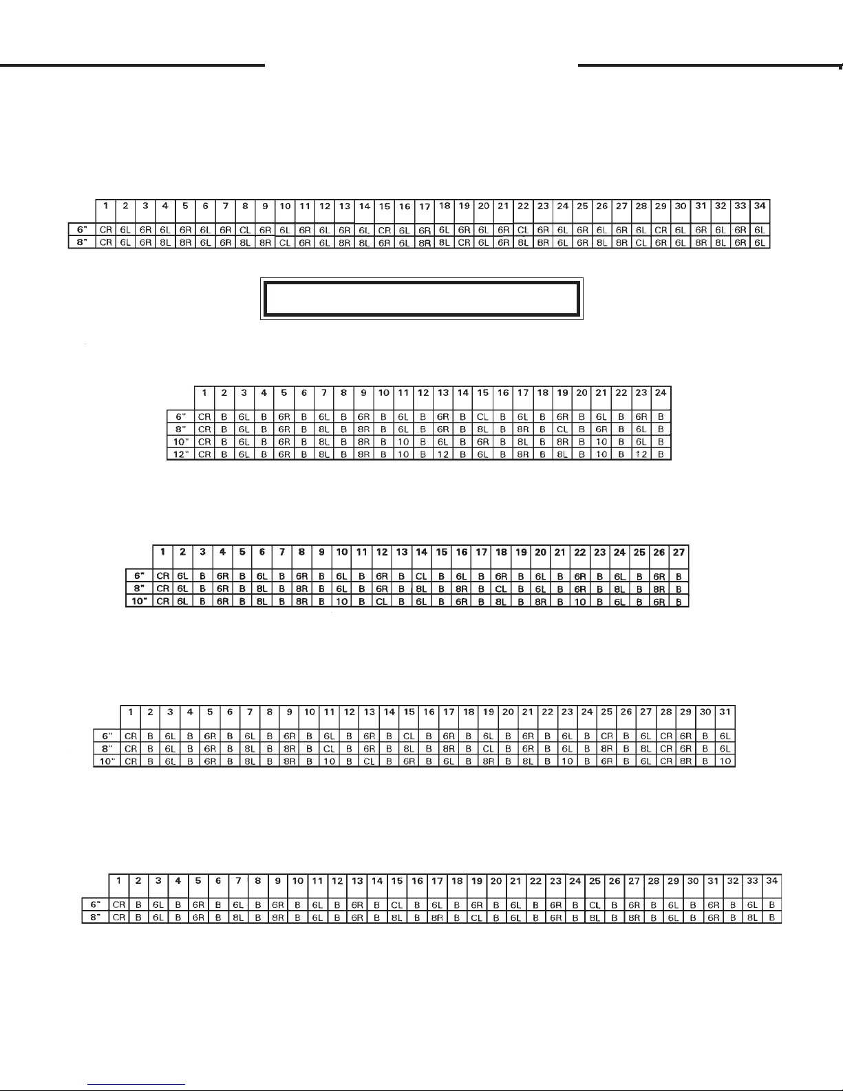
J
J
DIGGING CHAIN OPTIONS
2.00" PITCH DIGGING TOOTH STATION SEQUENCE
GENERAL INFORMATION
Every second link on a digging chain is a special link called a digging
station. These digging station links are designed so that digging teeth can
be bolted onto them in a variety of configurations. It is the number and the
make up of these different digging stations that make each chain unique.
The following tables show the number of digging stations there are in
each available 2.00" pitch digging chain. The digging tooth make up of
each digging station is given in code. The key to the code is located at the
below. Thus these charts will tell you what kind of digging tooth arrangement is at each digging station on each digging chain assembly. The actual
parts break down on each digging tooth arrangement is shown on the "Digging Tooth Station Break Down" diagrams located in this section following
the charts.
DIGGING TOOTH STATION KEY
CR - CENTER CUTTER, RIGHT 6R - 6" RIGHT STATION 8R - 8" RIGHT STATION
CL - CENTER CUTTER, LEFT 6L - 6" LEFT STATION 8L - 8" LEFT STATION
10 - 10" STATION 12 - 12" STATION B - BLANK STATION
TOOTH EVERY STATION
TRENCH
WIDTH
TRENCH
WIDTH
DIGGING TOOTH STATIONS
DIGGING TOOTH STATIONS
30" BOOM
36" BOOM
TRENCH
WIDTH
42" BOOM
DIGGING TOOTH STATIONS
5807
7-24-4
J
J
DIGGING CHAIN OPTIONS
2.00" PITCH DIGGING TOOTH STATION SEQUENCE
TRENCH
WIDTH
TRENCH
WIDTH
TRENCH
WIDTH
48" BOOM
DIGGING TOOTH STATIONS
TOOTH EVERY OTHER STATION
30" BOOM
DIGGING TOOTH STATIONS
36" BOOM
DIGGING TOOTH STATIONS
TRENCH
WIDTH
TRENCH
WIDTH
42" BOOM
DIGGING TOOTH STATIONS
48" BOOM
DIGGING TOOTH STATIONS
5808
7-24-02-3

JJ
DIGGING CHAIN OPTIONSDIGGING CHAIN OPTIONS
DIGGING CHAIN OPTIONS
DIGGING CHAIN OPTIONSDIGGING CHAIN OPTIONS
2.00" PITCH DIGGING TOOTH STATION BREAK DOWN
GENERAL INFORMATION
The following diagrams are the complete parts break downs of all the
different digging tooth arrangements used on the digging stations for 2.00" pitch
chains. The diagrams are frontal views according to the digging chain direction
of travel. All 2.00" pitch chains are made up of a combination of some or all of
these various digging tooth arrangements. See the "2.00" Pitch Digging Tooth
Station Sequence Charts" (located earlier in this section) to find out how the
arrangements are used for the various digging chains.
DIRT TOOTH, LEFT
PART #54431
DIRT TOOTH, RIGHT
1.56" SPACER TUBE
3.25" CAPSCREW
WITH NUT #1692
CENTER CUTTER, LEFT
DIRT TOOTH, LEFT
DIRT TOOTH, RIGHT
1.81" SPACER TUBE
PART #54432
PART #54628
PART #1347
CENTER CUTTER, RIGHT
PART #54431
PART #54432
PART #54440
6" LEFT STATION 6" RIGHT STATION
3.25" CAPSCREW
PART #1347
WITH NUT #1692
5809
3-2-92

J
DIGGING CHAIN OPTIONSDIGGING CHAIN OPTIONS
DIGGING CHAIN OPTIONS
DIGGING CHAIN OPTIONSDIGGING CHAIN OPTIONS
2.00" PITCH DIGGING TOOTH STATION BREAK DOWN
DIRT TOOTH, LEFT
PART #54431
DIRT TOOTH, RIGHT
PART #54432
SPACER BAR
PART #54439
1.81" SPACER TUBE
PART #54440
4.50" CAPSCREW
PART #1351
WITH NUT #1692
J
8" RIGHT STATION8" LEFT STATION
DIRT TOOTH, LEFT
PART #54431
DIRT TOOTH, RIGHT
PART #54432
10" CHAIN SPACER
PART #54441
3.25" CAPSCREW
PART #1347
WITH NUT #1692
6.50
10" STATION
5810
3-2-92
J
DIGGING CHAIN OPTIONSDIGGING CHAIN OPTIONS
DIGGING CHAIN OPTIONS
DIGGING CHAIN OPTIONSDIGGING CHAIN OPTIONS
2.00" PITCH DIGGING TOOTH STATION BREAK DOWN
DIRT TOOTH, LEFT
PART #54431
DIRT TOOTH, RIGHT
PART #54432
12" CHAIN SPACER
PART #54442
4.50" CAPSCREW
PART #1351
WITH FLAT WASHER #1527
AND NUT #1692
J
8.50
12" STATION
5811
3-2-92

J
DIGGING CHAIN OPTIONSDIGGING CHAIN OPTIONS
DIGGING CHAIN OPTIONS
DIGGING CHAIN OPTIONSDIGGING CHAIN OPTIONS
2.00" PITCH DIGGING CHAIN WIDTH CONVERSIONS
GENERAL INFORMATION
Digging chains can be modified to dig trenches in a variety of widths. By modifying an
existing chain, it can be used to dig the width you want and thus save going the expense of a whole
new digging chain assembly. This can be a considerable cost savings, however it is more work
than just installing a new digging chain assembly.
The information given below is a complete listing of all the possible chain width conversions
for 2.00" pitch chain for your trencher. Included in the listing is a break down of all the parts
(including part numbers and quantities) needed to make the conversion. Simply install the new
parts (and rearrange the old parts) so that the finished chain construction follows that described
in the “Digging Tooth Station Sequence” chart and the “Digging Tooth Station Break Down”
diagrams for 2.00" pitch chain (located elsewhere in this section).
It should be noted that this information only applies to modifying chains of the same length
and pitch. All components must be of the same pitch. You cannot intermix components of different
pitch.
J
CHAIN CONVERSIONS FOR 30" BOOMS - TOOTH EVERY STATION
1) FROM 6" WIDE TO 8" WIDE
REQ’D PART NO. DESCRIPTION
20 1351 .50"UNF X 4.50" Capscrew
2 54440 Space r Tube
10 54439 8" Spacer
1 53055 8" Crumber S hoe
2) FROM 8" WIDE TO 6" WIDE
REQ’D PART NO. DESCRIPTION
20 1347 .50"UNF X 3.25" Capscrew
2 54628 Space r Tube
1 53054 6" Crumber S hoe
3) FROM 6" WIDE TO 10" WIDE
REQ’D PART NO. DESCRIPTION
8 1692 .50" UNF High Hex Nut
16 1351 .50"UNF X 4.50" Capscrew
2 54431 Left Tooth
2 54432 Right Tooth
4 54441 10" Chain Spacer
1 53058 10" Crumber Shoe
8 54439 8" Spacer
6673
10-4-95

J
DIGGING CHAIN OPTIONSDIGGING CHAIN OPTIONS
DIGGING CHAIN OPTIONS
DIGGING CHAIN OPTIONSDIGGING CHAIN OPTIONS
2.00" PITCH DIGGING CHAIN WIDTH CONVERSIONS
4) FROM 10" WIDE TO 6" WIDE
REQ’D PART NO. DESCRIPTION
8 1347 .50"UNF X 3.25" Capscrew
4 54628 Space r Tube
4 54440 Space r Tube
1 53054 6" Crumber S hoe
5) FROM 6" WIDE TO 12" WIDE
REQ’D PART NO. DESCRIPTION
12 1692 .50" UNF High Hex Nut
28 1351 .50"UNF X 4.50" Capscrew
12 1527 .50" SAE Flat Washer
3 54431 Left Tooth
3 54432 Right Tooth
3 54441 10" Chain Spacer
3 54442 12" Chain Spacer
1 53059 12" Crumber Shoe
8 54439 8" Spacer
J
6) FROM 12" WIDE TO 6" WIDE
REQ’D PART NO. DESCRIPTION
16 1347 .50"UNF X 3.25" Capscrew
4 54628 Space r Tube
8 54440 Space r Tube
1 53054 6" Crumber S hoe
7) FROM 8" WIDE TO 10" WIDE
REQ’D PART NO. DESCRIPTION
8 1692 .50" UNF High Hex Nut
12 1347 .50"UNF X 3.25" Capscrew
2 54431 Left Tooth
2 54432 Right Tooth
4 54441 10" Chain Spacer
1 53058 10" Crumber Shoe
8) FROM 10" WIDE TO 8" WIDE
REQ’D PART NO. DESCRIPTION
4 1351 .50"UNF X 4.50" Capscrew
2 54628 Space r Tube
6 54440 Space r Tube
2 54439 8" Spacer
1 53055 8" Crumber S hoe
6674
10-4-95

J
DIGGING CHAIN OPTIONSDIGGING CHAIN OPTIONS
DIGGING CHAIN OPTIONS
DIGGING CHAIN OPTIONSDIGGING CHAIN OPTIONS
2.00" PITCH DIGGING CHAIN WIDTH CONVERSIONS
9) FROM 8" WIDE TO 12" WIDE
REQ’D PART NO. DESCRIPTION
12 1692 .50" UNF High Hex Nut
4 1347 .50"UNF X 3.25" Capscrew
8 1351 .50"UNF X 4.50" Capscrew
12 1527 .50" SAE Flat Washer
3 54431 Left Tooth
3 54432 Right Tooth
3 54441 10" Chain Spacer
3 54442 12" Chain Spacer
1 53059 12" Crumber Shoe
10) FROM 12" WIDE TO 8" WIDE
REQ’D PART NO. DESCRIPTION
2 54628 Space r Tube
10 54440 Spacer Tube
2 54439 8" Spacer
1 53055 8" Crumber S hoe
J
11) FROM 10" WIDE TO 12" WIDE
REQ’D PART NO. DESCRIPTION
4 1692 .50" UNF High Hex Nut
12 1351 .50"UNF X 4.50" Capscrew
12 1527 .50" SAE Flat Washer
1 54431 Left Tooth
1 54432 Right Tooth
3 54442 12" Chain Spacer
1 53059 12" Crumber Shoe
12) FROM 12" WIDE TO 10" WIDE
REQ’D PART NO. DESCRIPTION
8 1347 .50"UNF X 3.25" Capscrew
4 54440 Space r Tube
1 54441 10" Chain Spacer
1 53058 10" Crumber Shoe
CHAIN CONVERSIONS FOR 36" BOOMS - TOOTH EVERY STATION
1) FROM 6" WIDE TO 8" WIDE
REQ’D PART NO. DESCRIPTION
22 1351 .50"UNF X 4.50" Capscrew
2 54440 Space r Tube
11 54439 8" Spacer
1 53055 8" Crumber S hoe
6675
10-4-95

J
DIGGING CHAIN OPTIONSDIGGING CHAIN OPTIONS
DIGGING CHAIN OPTIONS
DIGGING CHAIN OPTIONSDIGGING CHAIN OPTIONS
2.00" PITCH DIGGING CHAIN WIDTH CONVERSIONS
2) FROM 8" WIDE TO 6" WIDE
REQ’D PART NO. DESCRIPTION
22 1347 .50"UNF X 3.25" Capscrew
2 54628 Space r Tube
1 53054 6" Crumber S hoe
3) FROM 6" WIDE TO 10" WIDE
REQ’D PART NO. DESCRIPTION
8 1692 .50" UNF High Hex Nut
20 1351 .50"UNF X 4.50" Capscrew
2 54431 Left Tooth
2 54432 Right Tooth
4 54441 10" Chain Spacer
1 53058 10" Crumber Shoe
10 54439 8" Spacer
J
4) FROM 10" WIDE TO 6" WIDE
REQ’D PART NO. DESCRIPTION
12 1347 .50"UNF X 3.25" Capscrew
2 54628 Space r Tube
6 54440 Space r Tube
1 53054 6" Crumber S hoe
5) FROM 8" WIDE TO 10" WIDE
REQ’D PART NO. DESCRIPTION
8 1692 .50" UNF High Hex Nut
10 1347 .50"UNF X 3.25" Capscrew
2 54431 Left Tooth
2 54432 Right Tooth
4 54441 10" Chain Spacer
1 53058 10" Crumber Shoe
6) FROM 10" WIDE TO 8" WIDE
REQ’D PART NO. DESCRIPTION
2 1351 .50"UNF X 4.50" Capscrew
8 54440 Space r Tube
1 54439 8" Spacer
1 53055 8" Crumber S hoe
6676
10-4-95

J
DIGGING CHAIN OPTIONSDIGGING CHAIN OPTIONS
DIGGING CHAIN OPTIONS
DIGGING CHAIN OPTIONSDIGGING CHAIN OPTIONS
2.00" PITCH DIGGING CHAIN WIDTH CONVERSIONS
CHAIN CONVERSIONS FOR 42" BOOMS - TOOTH EVERY STATION
1) FROM 6" WIDE TO 8" WIDE
REQ’D PART NO. DESCRIPTION
26 1351 .50"UNF X 4.50" Capscrew
2 54440 Space r Tube
13 54439 8" Spacer
1 53055 8" Crumber S hoe
2) FROM 8" WIDE TO 6" WIDE
REQ’D PART NO. DESCRIPTION
26 1347 .50"UNF X 3.25" Capscrew
2 54628 Space r Tube
1 53054 6" Crumber S hoe
J
3) FROM 6" WIDE TO 10" WIDE
REQ’D PART NO. DESCRIPTION
10 1692 .50" UNF High Hex Nut
24 1351 .50"UNF X 4.50" Capscrew
2 54431 Left Tooth
3 54432 Right Tooth
5 54441 10" Chain Spacer
1 53058 10" Crumber Shoe
12 54439 8" Spacer
4) FROM 10" WIDE TO 6" WIDE
REQ’D PART NO. DESCRIPTION
14 1347 .50"UNF X 3.25" Capscrew
4 54628 Space r Tube
6 54440 Space r Tube
1 53054 6" Crumber S hoe
5) FROM 8" WIDE TO 10" WIDE
REQ’D PART NO. DESCRIPTION
10 1692 .50" UNF High Hex Nut
12 1347 .50"UNF X 3.25" Capscrew
2 54431 Left Tooth
3 54432 Right Tooth
5 54441 10" Chain Spacer
1 53058 10" Crumber Shoe
6677
10-4-95

J
DIGGING CHAIN OPTIONSDIGGING CHAIN OPTIONS
DIGGING CHAIN OPTIONS
DIGGING CHAIN OPTIONSDIGGING CHAIN OPTIONS
2.00" PITCH DIGGING CHAIN WIDTH CONVERSIONS
6) FROM 10" WIDE TO 8" WIDE
REQ’D PART NO. DESCRIPTION
2 1351 .50"UNF X 4.50" Capscrew
2 54628 Space r Tube
8 54440 Space r Tube
1 54439 8" Spacer
1 53055 8" Crumber S hoe
CHAIN CONVERSIONS FOR 48" BOOMS - TOOTH EVERY STATION
1) FROM 6" WIDE TO 8" WIDE
REQ’D PART NO. DESCRIPTION
28 1351 .50"UNF X 4.50" Capscrew
2 54440 Space r Tube
14 54439 8" Spacer
1 53055 8" Crumber S hoe
J
2) FROM 8" WIDE TO 6" WIDE
REQ’D PART NO. DESCRIPTION
28 1347 .50"UNF X 3.25" Capscrew
2 54628 Space r Tube
1 53054 6" Crumber S hoe
CHAIN CONVERSIONS FOR 30" BOOMS - TOOTH EVERY OTHER STATION
1) FROM 6" WIDE TO 8" WIDE
REQ’D PART NO. DESCRIPTION
8 1351 .50"UNF X 4.50" Capscrew
4 54439 8" Spacer
1 53055 8" Crumber S hoe
2) FROM 8" WIDE TO 6" WIDE
REQ’D PART NO. DESCRIPTION
8 1347 .50"UNF X 3.25" Capscrew
1 53054 6" Crumber S hoe
3) FROM 6" WIDE TO 10" WIDE
REQ’D PART NO. DESCRIPTION
4 1692 .50" UNF High Hex Nut
8 1351 .50"UNF X 4.50" Capscrew
1 54431 Left Tooth
1 54432 Right Tooth
2 54441 10" Chain Spacer
1 53058 10" Crumber Shoe
4 54439 8" Spacer
6678
10-4-95

J
DIGGING CHAIN OPTIONSDIGGING CHAIN OPTIONS
DIGGING CHAIN OPTIONS
DIGGING CHAIN OPTIONSDIGGING CHAIN OPTIONS
2.00" PITCH DIGGING CHAIN WIDTH CONVERSIONS
4) FROM 10" WIDE TO 6" WIDE
REQ’D PART NO. DESCRIPTION
4 1347 .50"UNF X 3.25" Capscrew
2 54628 Space r Tube
2 54440 Space r Tube
1 53054 6" Crumber S hoe
5) FROM 6" WIDE TO 12" WIDE
REQ’D PART NO. DESCRIPTION
8 1692 .50" UNF High Hex Nut
16 1351 .50"UNF X 4.50" Capscrew
8 1527 .50" SAE Flat Washer
2 54431 Left Tooth
2 54432 Right Tooth
2 54441 10" Chain Spacer
2 54442 12" Chain Spacer
1 53059 12" Crumber Shoe
4 54439 8" Spacer
J
6) FROM 12" WIDE TO 6" WIDE
REQ’D PART NO. DESCRIPTION
8 1347 .50"UNF X 3.25" Capscrew
2 54628 Space r Tube
6 54440 Space r Tube
1 53054 6" Crumber S hoe
7) FROM 8" WIDE TO 10" WIDE
REQ’D PART NO. DESCRIPTION
4 1692 .50" UNF High Hex Nut
4 1347 .50"UNF X 3.25" Capscrew
1 54431 Left Tooth
1 54432 Right Tooth
2 54441 10" Chain Spacer
1 53058 10" Crumber Shoe
8) FROM 10" WIDE TO 8" WIDE
REQ’D PART NO. DESCRIPTION
2 54628 Space r Tube
2 54440 Space r Tube
1 53055 8" Crumber S hoe
6679
10-4-95

J
DIGGING CHAIN OPTIONSDIGGING CHAIN OPTIONS
DIGGING CHAIN OPTIONS
DIGGING CHAIN OPTIONSDIGGING CHAIN OPTIONS
2.00" PITCH DIGGING CHAIN WIDTH CONVERSIONS
9) FROM 8" WIDE TO 12" WIDE
REQ’D PART NO. DESCRIPTION
8 1692 .50" UNF High Hex Nut
8 1351 .50"UNF X 4.50" Capscrew
8 1527 .50" SAE Flat Washer
2 54431 Left Tooth
2 54432 Right Tooth
2 54441 10" Chain Spacer
2 54442 12" Chain Spacer
1 53059 12" Crumber Shoe
10) FROM 12" WIDE TO 8" WIDE
REQ’D PART NO. DESCRIPTION
2 54628 Space r Tube
6 54440 Space r Tube
1 53055 8" Crumber S hoe
J
11) FROM 10" WIDE TO 12" WIDE
REQ’D PART NO. DESCRIPTION
4 1692 .50" UNF High Hex Nut
8 1351 .50"UNF X 4.50" Capscrew
8 1527 .50" SAE Flat Washer
1 54431 Left Tooth
1 54432 Right Tooth
2 54442 12" Chain Spacer
1 53059 12" Crumber Shoe
12) FROM 12" WIDE TO 10" WIDE
REQ’D PART NO. DESCRIPTION
4 1347 .50"UNF X 3.25" Capscrew
4 54440 Space r Tube
1 53058 10" Crumber Shoe
CHAIN CONVERSIONS FOR 36" BOOMS - TOOTH EVERY OTHER STATION
1) FROM 6" WIDE TO 8" WIDE
REQ’D PART NO. DESCRIPTION
12 1351 .50"UNF X 4.50" Capscrew
6 54439 8" Spacer
1 53055 8" Crumber S hoe
2) FROM 8" WIDE TO 6" WIDE
REQ’D PART NO. DESCRIPTION
12 1347 .50"UNF X 3.25" Capscrew
1 53054 6" Crumber S hoe
6680
10-4-95

J
DIGGING CHAIN OPTIONSDIGGING CHAIN OPTIONS
DIGGING CHAIN OPTIONS
DIGGING CHAIN OPTIONSDIGGING CHAIN OPTIONS
2.00" PITCH DIGGING CHAIN WIDTH CONVERSIONS
3) FROM 6" WIDE TO 10" WIDE
REQ’D PART NO. DESCRIPTION
4 1692 .50" UNF High Hex Nut
8 1351 .50"UNF X 4.50" Capscrew
1 54431 Left Tooth
1 54432 Right Tooth
2 54441 10" Chain Spacer
1 53058 10" Crumber Shoe
4 54439 8" Spacer
4) FROM 10" WIDE TO 6" WIDE
REQ’D PART NO. DESCRIPTION
4 1347 .50"UNF X 3.25" Capscrew
4 54440 Space r Tube
1 53054 6" Crumber S hoe
J
5) FROM 8" WIDE TO 10" WIDE
REQ’D PART NO. DESCRIPTION
4 1692 .50" UNF High Hex Nut
8 1347 .50"UNF X 3.25" Capscrew
1 54431 Left Tooth
1 54432 Right Tooth
2 54441 10" Chain Spacer
1 53058 10" Crumber Shoe
6) FROM 10" WIDE TO 8" WIDE
REQ’D PART NO. DESCRIPTION
4 1351 .50"UNF X 4.50" Capscrew
4 54440 Space r Tube
2 54439 8" Spacer
1 53055 8" Crumber S hoe
CHAIN CONVERSIONS FOR 42" BOOMS - TOOTH EVERY OTHER STATION
1) FROM 6" WIDE TO 8" WIDE
REQ’D PART NO. DESCRIPTION
12 1351 .50"UNF X 4.50" Capscrew
6 54439 8" Spacer
1 53055 8" Crumber S hoe
2) FROM 8" WIDE TO 6" WIDE
REQ’D PART NO. DESCRIPTION
6 1347 .50"UNF X 3.25" Capscrew
1 53054 6" Crumber S hoe
6681
10-4-95

J
DIGGING CHAIN OPTIONSDIGGING CHAIN OPTIONS
DIGGING CHAIN OPTIONS
DIGGING CHAIN OPTIONSDIGGING CHAIN OPTIONS
2.00" PITCH DIGGING CHAIN WIDTH CONVERSIONS
3) FROM 6" WIDE TO 10" WIDE
REQ’D PART NO. DESCRIPTION
6 1692 .50" UNF High Hex Nut
12 1351 .50"UNF X 4.50" Capscrew
1 54431 Left Tooth
2 54432 Right Tooth
3 54441 10" Chain Spacer
1 53058 10" Crumber Shoe
6 54439 8" Spacer
4) FROM 10" WIDE TO 6" WIDE
REQ’D PART NO. DESCRIPTION
6 1347 .50"UNF X 3.25" Capscrew
2 54628 Space r Tube
4 54440 Space r Tube
1 53054 6" Crumber S hoe
J
5) FROM 8" WIDE TO 10" WIDE
REQ’D PART NO. DESCRIPTION
6 1692 .50" UNF High Hex Nut
1 54431 Left Tooth
2 54432 Right Tooth
3 54441 10" Chain Spacer
1 53058 10" Crumber Shoe
6) FROM 10" WIDE TO 8" WIDE
REQ’D PART NO. DESCRIPTION
2 54628 Space r Tube
4 54440 Space r Tube
1 53055 8" Crumber S hoe
CHAIN CONVERSIONS FOR 48" BOOMS - TOOTH EVERY OTHER STATION
1) FROM 6" WIDE TO 8" WIDE
REQ’D PART NO. DESCRIPTION
14 1351 .50"UNF X 4.50" Capscrew
2 54440 Space r Tube
7 54439 8" Spacer
1 53055 8" Crumber S hoe
2) FROM 8" WIDE TO 6" WIDE
REQ’D PART NO. DESCRIPTION
14 1347 .50"UNF X 3.25" Capscrew
2 54628 Space r Tube
1 53054 6" Crumber S hoe
6682
10-4-95

LL
MAINTENANCE
GENERAL MAINTENANCE
GENERAL INFORMATION
Your trencher was designed to be virtually maintenance free. Very
little effort is needed to keep it in top condition. It is however important to
follow these procedures to get full performance and longevity out of the
trencher.
LUBRICATION
The only lubrication your trencher needs is the greasing of the
headshaft end bearing. The bearing should be lubricated with an SAE multipurpose grease every 8 hours of operation. A grease zerk is installed in the
bearing to facilitate this task.
NOTE: Not all trenchers require lubricating of the headshaft bearing. Some
units have a sealed bearing that requires no maintenance. These units can
be identified by the absence of a grease zerk in the bearing.
IMPORTANT:
parts such as the digging chain or the idler wheel will only attract dirt, resulting in increased wear.
EVERY 40 HOURS OF OPERATION
Every 40 hours of operation the trencher should be inspected for
loose nuts, capscrews, bearings etc. Tighten as required, replace where
necessary. Clean equipment of all dirt, oil, grease, etc. This will assist you
in making visual inspections and help avoid overlooking worn or damaged
components. Keep all safety decals clean and legible. Replace if damaged
or worn.
DIGGING TOOTH REPLACEMENT
Sharp teeth are important to good performance. When teeth wear
out, production will drop sharply, increasing wear and tear on other components.
Cup teeth wear on the tip and side bulge in varying amounts. Wear
patterns change with different digging conditions. The following patterns
and captions are approximate and should be used as a guide to help you
determine your own best cost/benefit tooth replacement time. Normal
replacement should be made between 30% and 60% reduction in performance. Replacement is a bolt-on procedure. See Section J.
DO NOT lubricate any other part of the trencher! Lubricating
Ne w 20% Reduced 50% Reduced 70% Reduced Beyond
Performance Performance Performance Use
4445
3-3-92-2

MM
STORAGE
617 TRENCHER
GENERAL INFORMATION
The following storage procedures will help you to keep your trencher
in top condition. They will also help you get off to a good start the next
time your trencher is needed. We therefor strongly recommend that you
take the extra time to follow these procedures whenever your trencher will
not be used for an extended period of time.
PREPARATION FOR STORAGE
1. Clean the trencher exterior thoroughly, removing all mud, dirt, and
grease.
2. Tighten all loose bolts, nuts, and set screws.
3. Touch up unpainted and exposed areas with paint to prevent rust.
4 . Coat the digging chain with a thin covering of oil. Operate chain for a
short period to work the oil into the pins.
5 . Store the trencher in a dry and protected place. Leaving the trencher
outside, exposed to the elements will materially shorten its life.
6 . Inspect trencher for visible signs of wear, breakage or damage. Order
any parts required and make necessary repairs to avoid delays when
starting next season.
7 . Replace operating decals if damaged or in unreadable condition.
REMOVING FROM STORAGE
1. Remove all protective coverings
2. Check hydraulic hoses for deterioration and if necessary, replace.
3. During cold weather, operate the trencher slowly for a short time
before placing the unit under full load.
5797
2-26-92

N
N
TROUBLE SHOOTING
617 TRENCHER
GENERAL INFORMATION
Your trencher was designed to be as simple and as trouble free as possible.
The purpose of this section is to help you in the event that a problem does develop.
Why we cannot possibly cover every problem that might occur, you will find that
those that are most common are covered here.
PROBLEM: Digging chain will not turn
POSSIBLE CAUSE AND REMEDY:
1. Quick coupler not completely engaged. Check to see that all couplers are
matched pairs and engaged correctly. Check coupler hook-up information
(See Section E) for proper hydraulic hose routing.
2.
3.
4.
5.
6. Hydraulic motor failed. Be sure you have hydraulic flow to the motor. If oil
7.
Quick coupler failure. Check couplers for dirt, rust, or other contaminates
that could effect coupler engagement. Clean or replace couplers as needed.
Obstruction in hydraulic hose. Remove hydraulic hoses and couplers one at
a time and check flow through hose by blowing through the hose or by pour-
ing hydraulic fluid through the hose. Clean or replace hose as needed.
Skid steer relief valve stuck open. Have relief valve serviced and checked by
an authorized dealer.
Skid steer auxiliary valve not operating properly. See skid steer operator's
manual or dealer for information and help.
flow to motor is good, but motor will still not turn when detached from trencher
headshaft, remove motor and have it serviced or replaced as needed.
Headshaft bearings failed. Inspect headshaft bearings for free movement.
Check for binding or foreign matter jamming bearing. Clean or replace as
necessary.
8.
Boom end bearing failed. Inspect boom end bearing for free movement.
Check for binding or foreign matter jamming bearing. Clean or replace as
necessary.
5798
2-26-92

N
N
TROUBLE SHOOTING
617 TRENCHER
9. Digging chain to tight. Digging chain should only be tight enough to remain
on sprockets while turning under load. Their should be some sag in the
chain. If too tight, loosen chain by the adjusting nut(s) on the boom.
10.
11.
PROBLEM: Trencher does not dig fast enough
POSSIBLE CAUSE AND REMEDY:
1.
2.
3.
Sand build-up in tooth root of sprocket. Sand can build up in the sprockets
effectively increasing the chain tension. Raise the boom out of the ditch and
reverse the digging chain on the trencher, then run the trencher out of the
trench to clear the sprockets. Reinstall the chain in its correct digging direc-
tion and readjust chain tension.
Digging sprocket clamp loose on headshaft. Observe if the headshaft is
turning. If shaft is turning but sprocket is not, stop the trencher and tighten the
sprocket clamp.
Digging teeth worn. See maintenance Section L in this manual. Inspect
teeth and replace as needed.
Skid steer relief valve set too low. See skid steer operator's manual and or
dealer for proper relief valve service and adjustment.
Quick coupler or hose restriction. Inspect couplers and hoses for dirt, rust,
and other contaminates and repair or replace as needed.
4. Hydraulic system over heating. Shut the trencher and skid steer down and
allow oil to cool. Repeated stalling of the trencher will cause the oil to over
heat. Avoid excessive stalling.
5.
PROBLEM: Hydraulic oil over heating
POSSIBLE CAUSE AND REMEDY:
1.
Cutting a ditch size beyond the ability of the skid steer. Your trencher is
powered by oil from the skid steers auxiliary hydraulic system. The horse-
power transmitted through the auxiliary hydraulics is substantially less than
that of the engine.
Skid steer relief valve set too low. See skid steer operator's manual and/or
dealer for proper relief valve service and adjustment.
5799
2-26-92

N
N
TROUBLE SHOOTING
617 TRENCHER
2. Quick coupler or hose restriction. Inspect couplers and hoses for dirt, rust,
and other contaminates and repair or replace as needed.
3. Motor or hose size not balanced to skid steer. A hose or a motor that is too
small can cause added internal friction and resultant heat build-up. Check
mounting kit parts list and diagram (See Section E) for proper hose size and
type.
4.
Skid steer not equipped with oil cooler or sufficient sump capacity. Check
with your skid steer dealer for information and availability of auxiliary cooling
and sump kits. Install if available. If not available stop skid steer and tren-
cher and allow them to cool when they get too hot.
5800
2-26-92
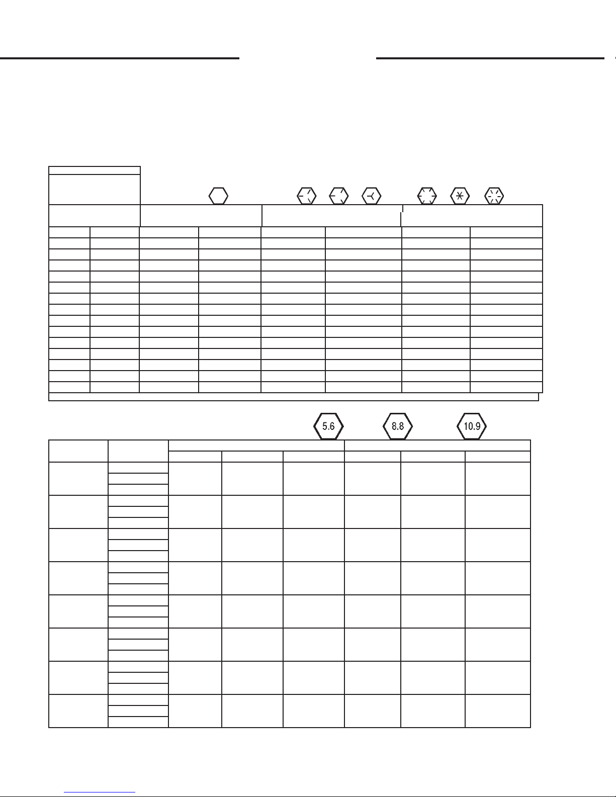
O O
BOLT TORQUE
BOLT TO RQUE SPECIFI CATIO NS
GENERAL TORQUE SPECIFICATION TABLE
Use the foll owing torques when special torques are not given. These values apply to fasteners as
received from suppliers, dry, or when lubricated with normal engine oil. They do not apply if special
graphi ted or moly disulphi de greases or other extrem e pressure lubri cants are used. Thi s appli es to both
UNF and UNC threads. Remember to always use grade fi ve or better when replacing bol ts.
SAE Grade No. 2 5 8*
Bolt head identification
marks as per grade.
NOTE: Manufacturing
Marks Will Vary
Inches Millimeters Min. Max. Min. Max. Min. Max. Min. Max. Min. Max. Min. Max.
1-1/8 25.58 - - - - 800 880 1084.8 1193.3 1280 1440 1735.7 1952.6
1-1/4 31.75 - - - - 1120 1240 1518.7 1681.4 1820 2000 2467.9 2712.0
1-3/8 34.93 - - - - 1460 1680 1979.8 2278.1 2380 2720 3227.3 3688.3
1-1/2 38.10 - - - - 1940 2200 2630.6 2983.2 3160 3560 4285.0 4827.4
TORQUE TORQUE TORQUE
Bolt Size P ounds Feet Newton-Meters Pounds Feet Ne wton-Meters Pounds Feet N ewton-Meters
1/4 6.35 5 6 6.8 8.13 9 11 12.2 14.9 12 15 16.3 30.3
5/16 7.94 10 12 13.6 16.3 17 20.5 23.1 27.8 24 29 32.5 39.3
3/8 9.53 20 23 27.1 31.2 35 42 47.5 57.0 45 54 61.0 73.2
7/16 11.11 30 25 40.7 47.4 54 64 73.2 86.8 70 84 94.9 113.9
1/2 12.70 45 52 61.0 70.5 80 96 108.5 130.2 110 132 149.2 179.0
9/16 14.29 65 75 88.1 101.6 110 132 149.2 179.0 160 192 217.0 260.4
5/8 15.88 95 105 128.7 142.3 150 180 203.4 244.1 220 264 298.3 358.0
3/4 19.05 150 185 203.3 250.7 270 324 366.1 439.3 380 456 515.3 618.3
7/8 22.23 160 200 216.8 271.0 400 480 542.4 650.9 600 720 813.6 976.3
1 25.40 250 300 338.8 406.5 580 696 786.5 943.8 900 1080 1220.4 1464.5
* Thick Nuts must be used with Grade 8 bolts
METRIC BOLT TORQUE SPECIFICATIONS
Coarse Thread Fine Thread
Size of Sc rew Grade No. Ptich (mm) Pounds Feet Newton-Meters P itch (mm) Pounds Feet Newton-Meter s
5.6 3.6-5.8 4.9-7.9 - -
M6 8.8 1.0 5.8-9.4 7.9-12.7 - - -
10.9 7.2-10 9.8-13.6 - -
5.6 7.2-14 9.8-19 12-17 16.3-23
M8 8.8 1.25 17-22 23-29.8 1.0 19-27 25.7-36.6
10.9 20-26 27.1-35.2 22-31 29.8-42
5.6 20-25 27.1-33.9 20-29 27.1-39.3
M10 8.8 1.5 34-40 46.1-54.2 1.25 35-47 47.4-63.7
10.9 38-46 51.5-62.3 40-52 54.2-70.5
5.6 28-34 37.9-46.1 31-41 42-55.6
M12 8.8 1.75 51-59 69.1-79.9 1.25 56-68 75.9-92.1
10.9 57-66 77.2-89.4 62-75 84-101.6
5.6 49-56 66.4-75.9 52-64 70.5-86.7
M14 8.8 2.0 81-93 109.8-126 1.5 90-106 122-143.6
10.9 96-109 130.1-147.7 107-124 145-168
5.6 67-77 90.8-104.3 69-83 93.5-112.5
M16 8.8 2.0 116-130 157.2-176.2 1.5 120-138 162.6-187
10.9 129-145 174.8-196.5 140-158 189.7-214.1
5.6 88-100 119.2-136 100-117 136-158.5
M18 8.8 2.0 150-168 203.3-227.6 1.5 177-199 239.8-269.6
10.9 175-194 237.1-262.9 202-231 273.7-313
5.6 108-130 146.3-176.2 132-150 178.9-203.3
M20 8.8 2.5 186-205 252-277.8 1.5 206-242 279.1-327.9
10.9 213-249 288.6-337.4 246-289 333.3-391.6
3915
6-8-95-2

617 TRENCHER SPECIFICATIONS
DESCRIPTION SPECS
A. Trench Depth w/auger touching
ground, 65° digging angle
30" Boom ........................................................... 30"
36" Boom ........................................................... 36"
48" Boom ........................................................... 48"
B. Trench Width - SEE CHART
D. Recommended Trenching Angle .............................. 6 5 °
E. Headshaft Height........................................................8 "
F. Trencher Length
30" Boom ........................................................... 66"
36" Boom ........................................................... 73"
48" Boom ........................................................... 86"
G. Trencher Width......................................................... 48"
H. Trencher Height........................................................ 32"
S. Side Shift
Right of Center................................................... 17"
U. Spoil Discharge Reach ............................................. 18"
Weight w/ 3' Boom and 6" Chain .......................... 925#
Hydraulic System Requirements:
Pump.............................................................11-20 GPM
Operating Pressure ...................................2000-2400 PSI
(B) Available Trench Widths
SPECIFICATIONS AND DESIGN ARE
SUBJECT TO CHANGE WITHOUT
NOTICE AND WITHOUT LIABILITY
THEREFORE. WHEREVER APPLICABLE SPECIFICATIONS ARE IN
ACCORDANCE WITH SAE
STANDARDS.
Bradco Trenchers are covered
by a one year limited warranty.
Printed in U.S.A.
COPYRIGHT 2-92
BRADCO®
P.O. Box 266 · Delhi, Iowa 52223 USA
(319) 922-2981 · (800) 922-2981
Fax 319-922-2130
A Division of American Trencher Inc.
Construction Machinery Since 1964
S-342
1-29-92
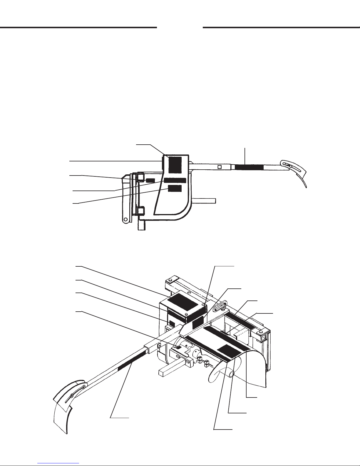
Q
Q
DECALS
DECAL PLACEMENT
617 TRENCHER
GENERAL INFORMATION
The diagram on this page shows the location of all the decals used on the
617 trencher. The decals are identified by their part numbers, with reductions of
the actual decals located on the following pages. Use this information to order
replacements for lost or damaged decals. Be sure to read all decals before
operating the trencher. They contain information you need to know for both
safety and trencher longevity.
4495
4350
40113
40114
4167
40113
4338
4084
4498
40161
40113
40114
40116
40115
40161
4105
40117
4498
5822
9-15-92-2

Q
Q
DECALS
PART #4167
NO STEP
PART #4498
DANGER!
PART #4495
WARNING! GUARDS
PART #4350
SERIAL NUMBER TAG
5823
7-22-02-2

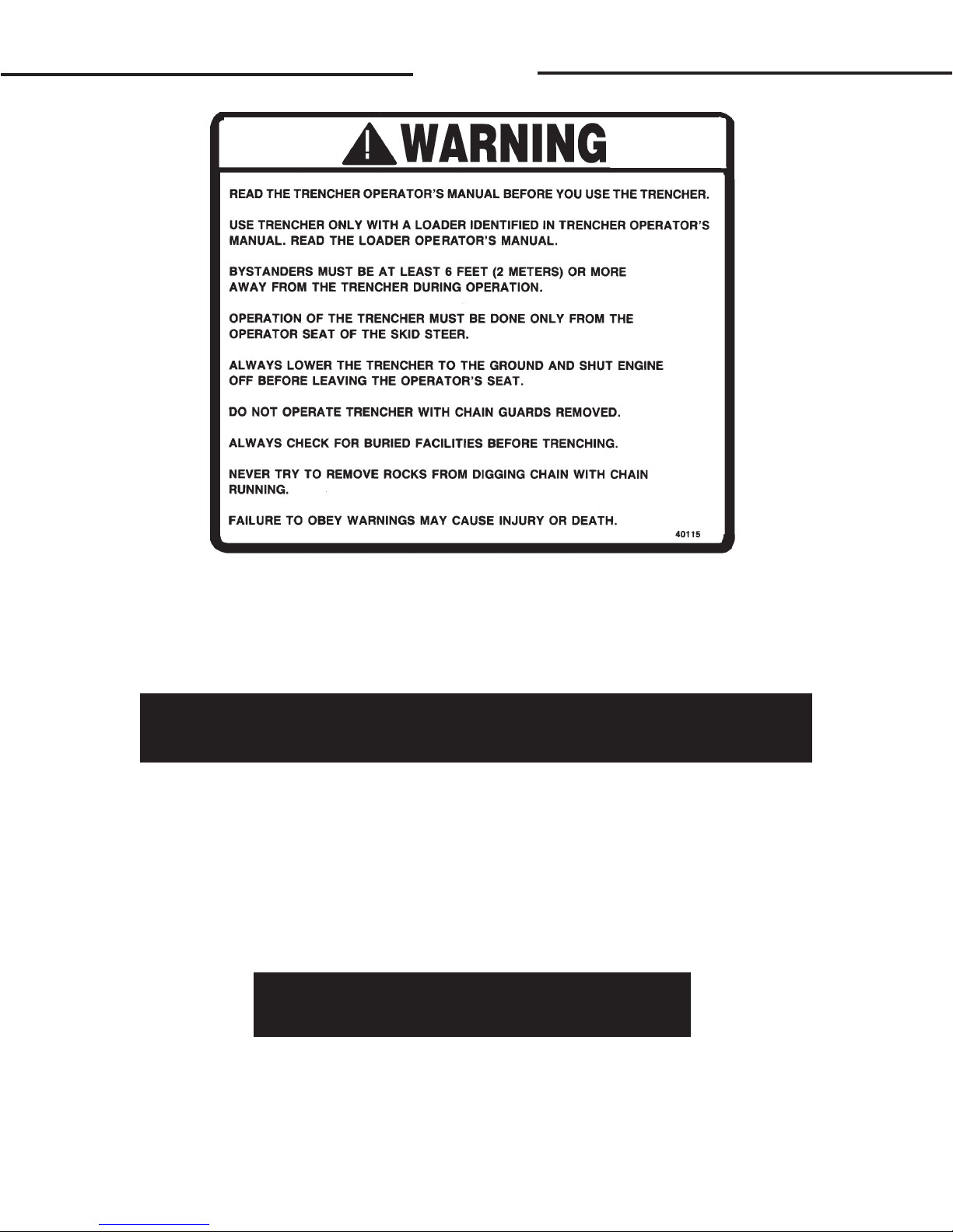
Q
Q
DECALS
PART #40115
WARNING! GENERAL
DANGER STAND CLEAR
PART #4105
DANGER STAND CLEAR
STAND CLEAR
PART #40161
STAND CLEAR
5825
7-22-02-3

RR
PREDELIVERY CHECKLIST
617 TRENCHER
GENERAL INFORMATION
The following is a list of areas that should be inspected by the dealer prior
to delivery of the trencher to the customer. The customer should check the list
and make sure that the dealer has completed the inspection. Completion of this
checklist will help insure that the customer receives the trencher in complete
working order, ready to install.
PREDELIVERY CHECKLIST - CHECK AND ADJUST AS NECESSARY
1. Check and lubricate trencher if necessary. See "Lubrication" Sec-
tion H.
2. Visually inspect the trencher for bent, loose, cracked, damaged or
missing parts. Check for any other irregularities.
3. Check all hydraulic connections for leaks an all hoses for proper
positioning to reduce chafing and binding.
4. Check the trencher's digging chain adjustment. See "Operating
Instructions - Chain Tension Adjustment" Section G.
5. Check trencher attachment bolts for tightness. Retighten after the
first eight working hours, and after every forty working hour interval
thereafter. See "Bolt Torque" Section O.
6. Make sure decals are not damaged or missing and are in their
correct location. See "Decals" Section Q.
7. Complete and return the manufacturers "Warranty Validation Form"
and sign your dealership predelivery checklist.
8. Operator to read the FIEI Trencher Safety Manual provided, before
operating trencher.
5801
2-26-92

S
S
LIMITED WARRANTY
EFFECTIVE ON PRODUCTS MANUFACTURED AFTER JANUARY 1, 2001
All new BRADCO products are warranted to be free from defects in
materials or workmanship which may cause failure under normal usage and
service when used for the purpose intended.
In the event of failure within twenty four (24) months from initial
retail sale, lease or rental date (excluding cable, ground engaging parts such
as sprockets, digging chain, bearings, teeth, tamping and demolition heads,
blade cutting edges, pilot bits, auger teeth, auger heads & broom bristles), if
after examination, BRADCO determines failure was due to defective material
and/or workmanship, parts will be repaired or replaced. BRADCO may
request defective part or parts be returned prepaid to them for inspection at
their place of business at Delhi, Iowa, or to a location specified by
BRADCO.
Any claims under this warranty must be made within fifteen (15)
days after the Buyer learns of the facts upon which such claim is based. All
claims not made in writing and received by BRADCO within the time period
specified above shall be deemed waived.
THIS WARRANTY IS IN LIEU OF ALL OTHER WARRANTIES EXPRESSED OR IMPLIED AND THERE ARE NO WARRANTIES OF MERCHANTABILITY OR OF FITNESS FOR A PARTICULAR PURPOSE. IN NO EVENT
SHALL BRADCO BE LIABLE FOR CONSEQUENTIAL OR SPECIAL DAMAGE.
BRADCO'S LIABILITY FOR ANY AND ALL LOSSES AND DAMAGES
TO BUYER, RESULTING FROM ANY CAUSE WHATSOEVER, INCLUDING
BRADCO'S NEGLIGENCE, IRRESPECTIVE OF WHETHER SUCH DEFECTS
ARE DISCOVERABLE OR LATENT, SHALL IN NO EVENT EXCEED THE PURCHASE PRICE OF THE PARTICULAR PRODUCTS WITH RESPECT TO
WHICH LOSSES OR DAMAGES ARE CLAIMED, OR, AT THE ELECTION OF
BRADCO, THE REPAIR OR REPLACEMENT OF DEFECTIVE OR DAMAGED
PRODUCTS.
3924
1-29-01-6
 Loading...