

Page 1

BARCODE READER
USER MANUAL
V 2.1
EN
Page 2
1
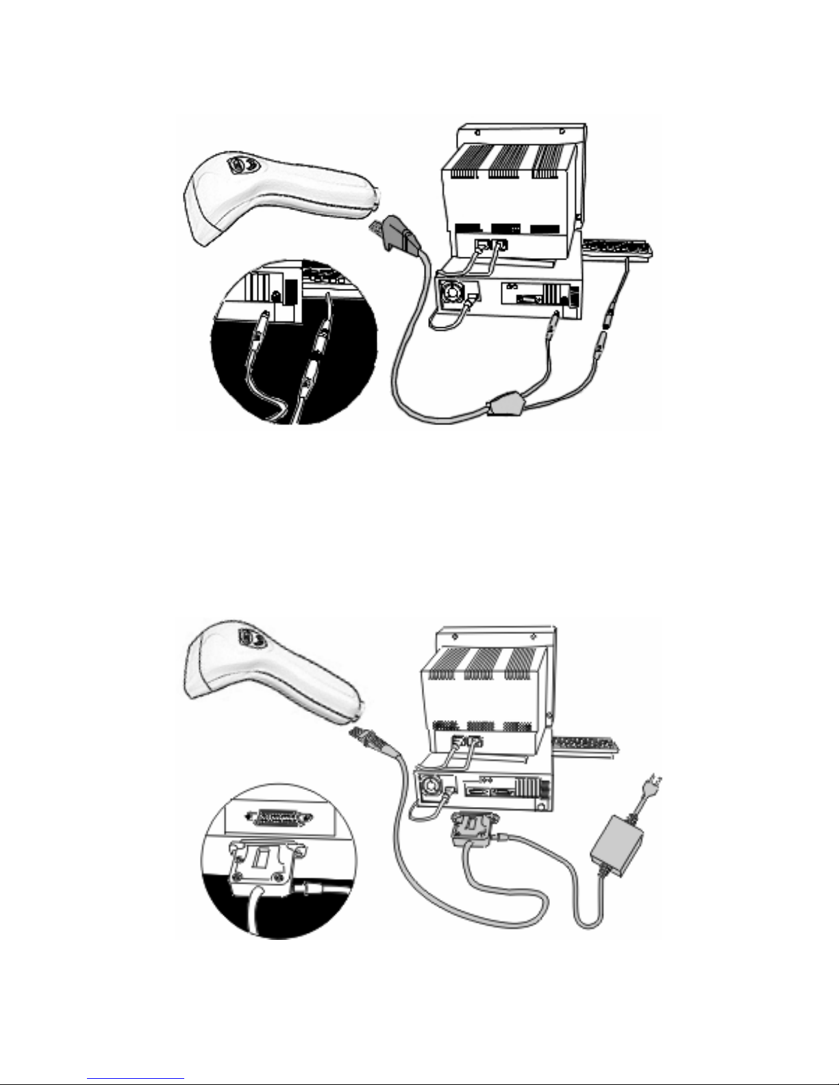
INSTALLATION OF YOUR DEVICE
PS-2 Connection
RS-232 Connection (need 5Volts power supply)
Page 3
2
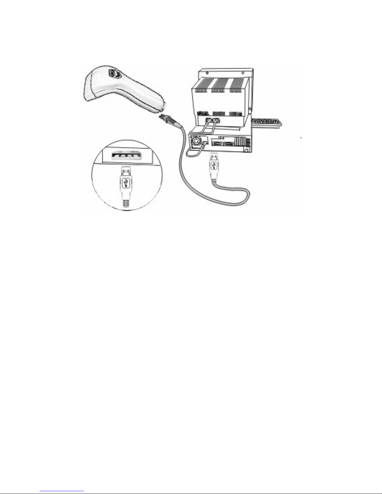
INSTALLATION OF YOUR DEVICE
USB Connection
Page 4

3
USING THIS MANUAL TO SETUP YOUR DEVICE
To set up all the necessary functions you can use the
following barcode menus.
Using these barcodes, you should enter in program
mode, scan the required command symbol then exit
from program mode.
The general procedure is the following:
-1) Scan the command symbol “PROGRAM”
-2) Scan one or more parameters
-3) Scan the command symbol “END”
(note)
Code 2/5 symbologies have an unchecked reading
mode, so that, you could set a fixed code length to
avoid any reading errors.
Following is the correct procedure:
-1) Scan the command symbol “PROGRAM”
-2) Scan the command symbol “FIXED LENGTH”
-3) Scan the command symbol “END”
The first two scanned barcodes 2/5 will be stored as
fixed length values.
The following procedure will reset the above
selection:
-1) Scan the command symbol “PROGRAM”
-2) Scan the command symbol “FIXED LENGTH OFF”
-3) Scan the command symbol “END”
Page 5

4
COMPLEX DEVICE SETTINGS
Set MIN/MAX barcode lengt:
-1) Scan the command symbol “PROGRAM”
-2) Scan the symbol “SET MAX&MIN”
-3) Scan barcode symbology (i2/5, 39,… etc…)
-4) Scan the symbol “MM” or “NN” (max or min)
-5) Scan 2 digits from the ASCII table
-6) Scan the symbol “SET MAX&MIN”
-7) Scan the command symbol “END”
Set PREAMBLE/POSTAMBLE
-1) Scan the command symbol “PROGRAM”
-2) Scan the symbol “PREAMBLE/POSTAMBLE”
-3) Scan up to 16 characters from the ASCII table
-4) Scan the symbol “PREAMBLE/POSTAMBLE”
-5) Scan the command symbol “END”
Set RS-232 to KEYBOARD WEDGE
-1) Scan the command symbol “PROGRAM”
-2) Scan the symbol “RS-232 TO KB WEDGE”
-3) Scan the RS-232 parameters (bps, data, parity,…)
-4) Scan the RX modes
-a) COUNTER ENABLE(wait for a fixed number of
characters to convert the received message)
-b) CODE ENABLE(wait for an ASCII character as
record terminator to convert the received message)
-5a) Scan the command symbol “COUNTER SET”,
scan 3 digits from the ASCII table then scan once
more the command symbol “CODE SET”
-5b) Scan the command symbol “CODE SET”, scan
the characters you whant to set as RX message
terminator from the ASCII table, then scan once more
the command symbol “CODE SET”.
-6) Scan the command symbol “END”
Page 6

5
COMPATIBLE PRODUCTS:
This manual could be used to setup the decoder
section of the following EIA products:
- FORCE (CCD SCANNER)
- ROCK (LASER SCANNER)
- THUNDER (PORTABLE TERMINAL)
- OTHER FUTURE MODELS…
Page 7
6
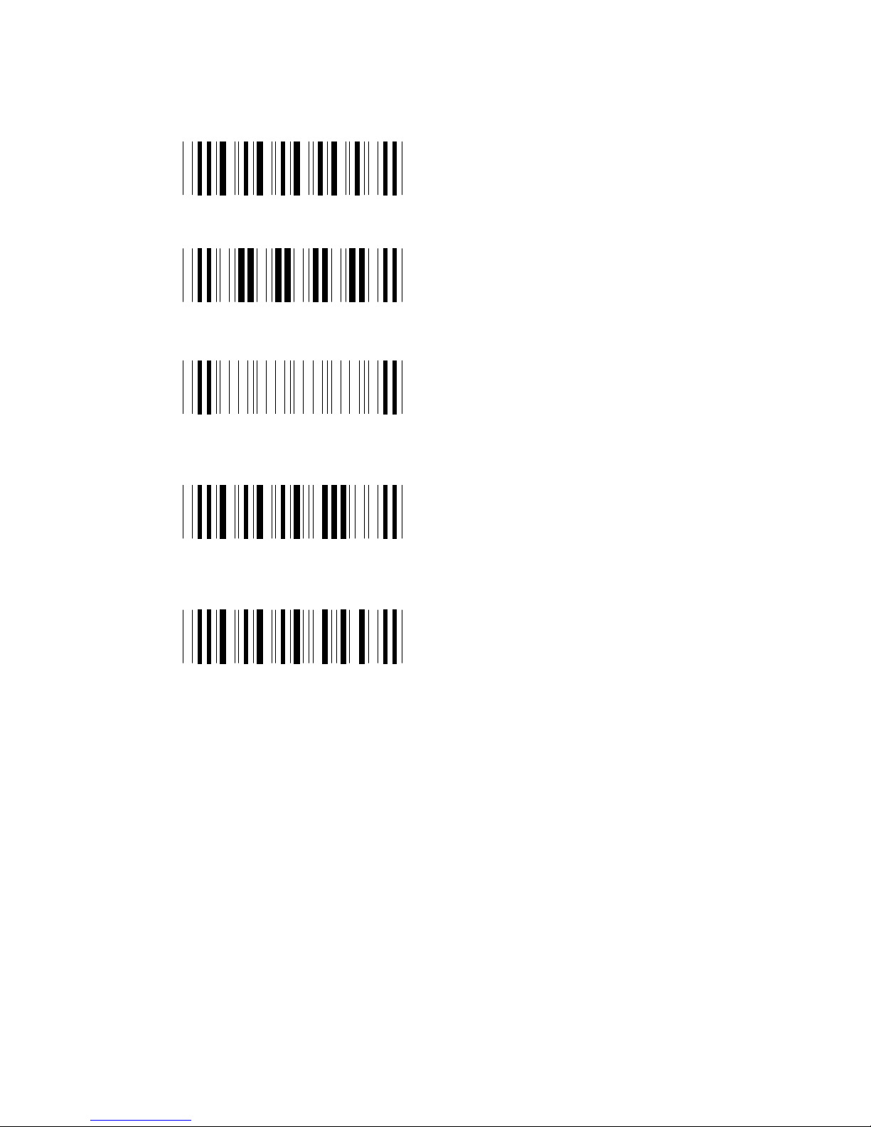
PARAMETERS SETTING
ENTER/EXIT SETUP
PROGRAM
DEFAULT
END
VER. CODE DISABLE
VER. CODE ENABLE
Page 8

7
I/O INTERFACE
Device & Interface Selection
KEYBOARD WEDGE*
PC/AT
PS/2
RS-232 SERIAL
RS-232 TO KB-WEDGE
WAND EMULATION
OCIA
TX Wand Emulation as
Code-39
TX
Wand Emulation as as EAN.
Scan this code then scan 1,2 or 3
from the ASCII table to indicate
the mode you whant to use:
AUTO, EAN-8 or EAN-13 then
scan this code once more.
Page 9

8
BARCODE SIMBOLOGY
Symbologies Selection
CODE-39 DISABLE
CODE-39 ENABLE*
FULL ASCII CODE-39*
STANDARD CODE-39
CODE-128 DISABLE
CODE-128 ENABLE
CODE-93 DISABLE
CODE-93 ENABLE
CODE-32 ENABLE
CODE-32 DISABLE
ISBN DISABLE
ISBN ENABLE
Page 10

9
Symbology Setting (I 2/5)
I 2/5 DISABLE
I 2/5 ENABLE*
FIXED LENGTH ON*
FIXED LENGTH OFF
1
st
DIGIT SUPPRESS
LAST DIGIT SUPPRESS
NO DIGIT SUPPRESS*
Page 11

10
Symbology Setting (CODE 128)
EAN-128 DISABLE*
EAN-128 ENABLE
EAN-128 SEPAR. SET
CHECK DIGIT DISABLE
CHECK DIGIT ENABLE*
Page 12

11
Symbology Setting (S 2/5)
S 2/5 DISABLE
S 2/5 ENABLE*
FIXED LENGTH ON*
FIXED LENGTH OFF
ADD CHK-DIGIT
VERIFY CHK-DIGIT
DON’T ADD CHK-DIGIT
Page 13

12
Symbology Setting (UPC-A)
UPC-A DISABLE
UPC-A ENABLE*
LEADING DIGIT SEND*
LDNG. DIGIT NOT SENT
ADD CHK-DIGIT*
DON’T ADD CHK-DIGIT
Page 14

13
Symbology Setting (UPC-E)
UPC-E DISABLE
UPC-E ENABLE*
LEADING DIGIT SEND*
LDNG. DIGIT NOT SENT
ADD CHK-DIGIT*
DON’T ADD CHK-DIGIT
ZERO EXP. ENABLE
ZERO EXP. DISABLE*
Page 15

14
Symbology Setting (EAN-8)
..7M
EAN-8 DISABLE
EAN-8 ENABLE*
LEADING DIGIT SEND*
LDNG. DIGIT NOT SENT
ADD CHK-DIGIT*
DON’T ADD CHK-DIGIT
Page 16

15
Symbology Setting (EAN-13)
EAN-13 DISABLE
EAN-13 ENABLE*
LEADING DIGIT SEND*
LDNG. DIGIT NOT SENT
ADD CHK-DIGIT*
DON’T ADD CHK-DIGIT
Page 17
16
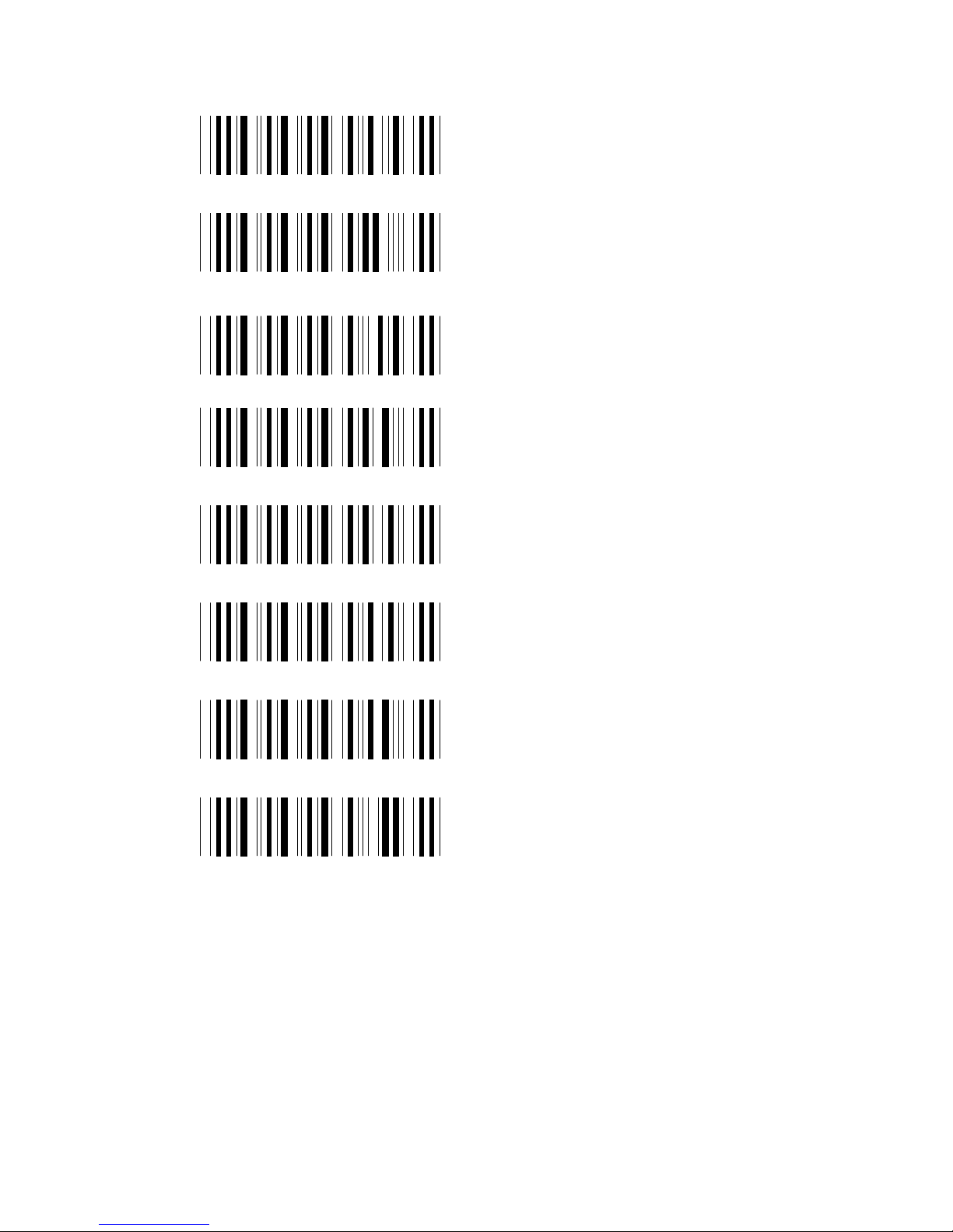
Symbology Setting (EAN/UPC SUPPLEMENTAL)
2 DIGIT SUPPL. DISAB.*
2 DIGIT SUPPL. ENAB.
5 DIGIT SUPPL. DISAB.*
5 DIGIT SUPPL. ENAB.
SPACE SEPARATOR ON
SPACE SEPAR. OFF
TRANSMIT IF PRESENT
MUST BE PRESENT
Page 18

17
Symbology Setting (CODABAR)
CODABAR DISABLE
CODABAR ENABLE*
START/STOP SEND*
START/STOP NOT SENT
Page 19

18
Symbology Setting (MSI)
MSI DISABLE
MSI ENABLE*
DOUBLE MOD 10
MOD 11 PLUS MOD 10
SINGLE MOD 10
SEND
NOT SENT*
Page 20

19
Symbology Setting (CODE-11)
CODE-11 DISABLE
CODE-11 ENABLE*
ONE CHECK DIGITS
TWO CHECK DIGITS
SEND
NOT SENT*
Page 21

20
RS-232 SERIAL PARAMETERS
Baud Rate
300
1200
2400
4800
9600
19200*
38400
Page 22
21
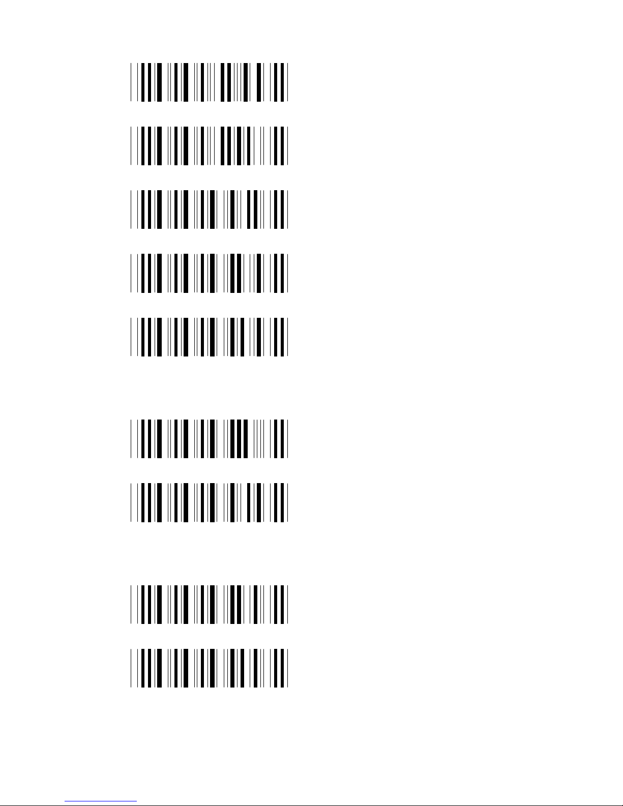
Parity
EVEN
ODD
MARK
SPACE
NONE
Data Bits
7 BITS*
8 BITS*
ACK/NACK protocol
OFF*
ON
Page 23

22
RS-232 additional parameters
CTS/RTS DISABLE*
CTS/RTS ENABLE
RS-485 ENABLE
RS-485 DISABLE*
LRC ENABLE
LRC DISABLE*
Page 24
23
RS-232 TO KBD-WEDGE PARAMETERS
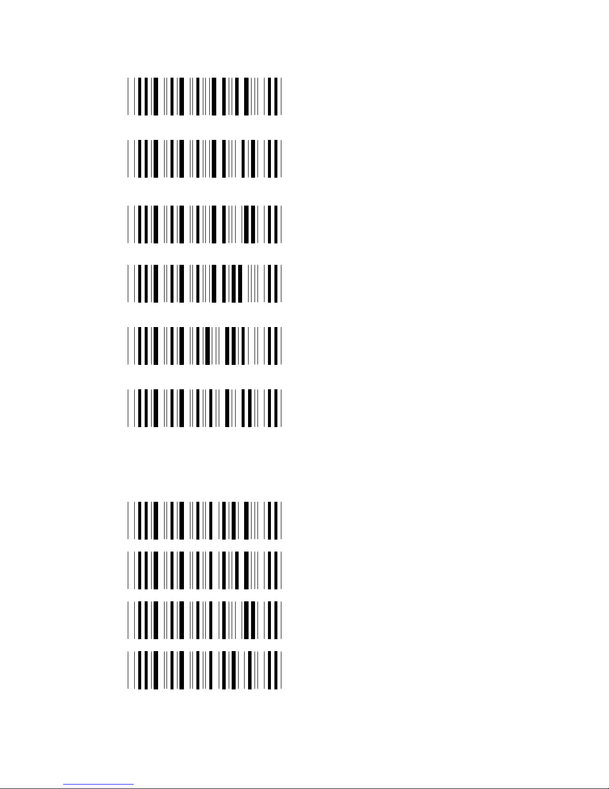
Conversion modes and terminator status
COUNTER ENABLE*
COUNTER SET
(01/99 DEFAULT-15)
CODE ENABLE
CODE SET
(ASCII CODE 01/7F)
TERMINATOR PASS
TERMINATOR CUT
DATA FORMAT
Terminators
ENTER (CR+LF)*
FIELD-EXIT (CR)
RETURN (LF)
NONE
Page 25
24
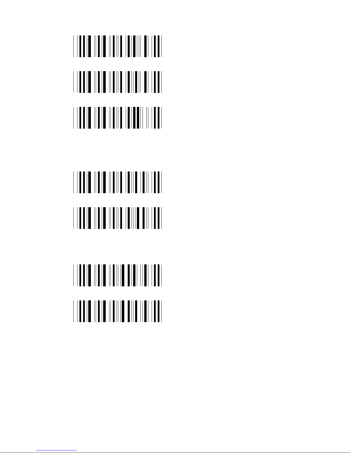
Code-ID
NONE*
USER DEFINED
DEFAULT
Data Length
EXCLUDE*
INCLUDE
Preamble / Postamble
PREAMBLE
POSTAMBLE
Page 26

25
Define Code-ID
DEFINE CODE-ID
CODE-39 FULL ASCII
CODE-39 STANDARD
EAN-13
UPC-A
EAN-8
UPC-E
I 2/5
Page 27

26
Define Code-ID
CODABAR
CODE-128
CODE-93
S 2/5
MSI
CODE-11
Page 28
27
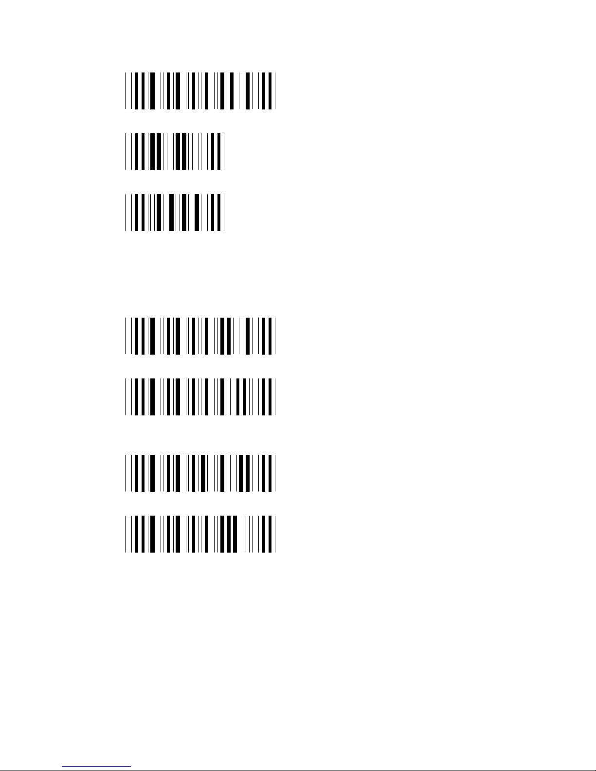
Custom Code Editing
SET EDIT MODE
SELECT FROM LEFT
SELECT FROM RIGHT
Scan SET EDIT MODE, Scan LEFT or RIGHT then
scan 2 digits from the ASCII table to select the
required length and scan LEFT or RIGHT once more.
CUSTOM MODE ENAB.
(Enable above setting)
CUSTOM MODE DISAB.*
(Disable above setting)
FULL DATA EDIT DISAB
(Disable following setup)
FULL DATA EDIT SETUP
Scan FULL DATA EDIT SETUP then scan 2 digits
from the ASCII table to select the start position, scan
the “.” Character and 2 more digits as the required
string length, close this procedure by scanning once
more the above barcode.
Page 29

28
READER FUNCTIONS
Laser ON timeout
NONE*
SHORT
MEDIUM
LONG
SCURITY LEVEL
(Redudancy on decoding)
Scan the above barcode then scan
1, 2, 3 from the ASCII table to
select how many attempt the
decoder should do before a good
reading, then scan thi barcode
once more to close this procedure.
Page 30
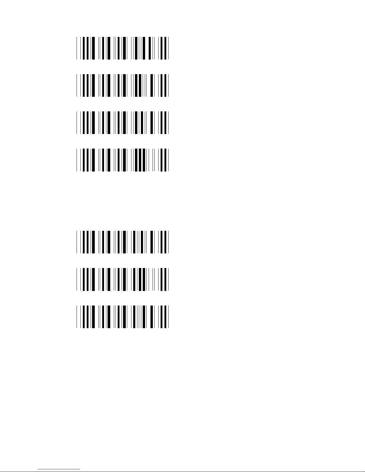
29
Beep Tone on decoding
NONE
LOW
MEDIUM*
HIGH
Reading mode
Switch mode*
Flash mode
Repeat mode
Page 31

30
Intercharacter delay
1 ms *
5 ms
10 ms
20 ms
50 ms
100 ms
Page 32

31
Intermessage delay
NONE *
50 ms
200 ms
500 ms
1 sec
2 sec
Page 33
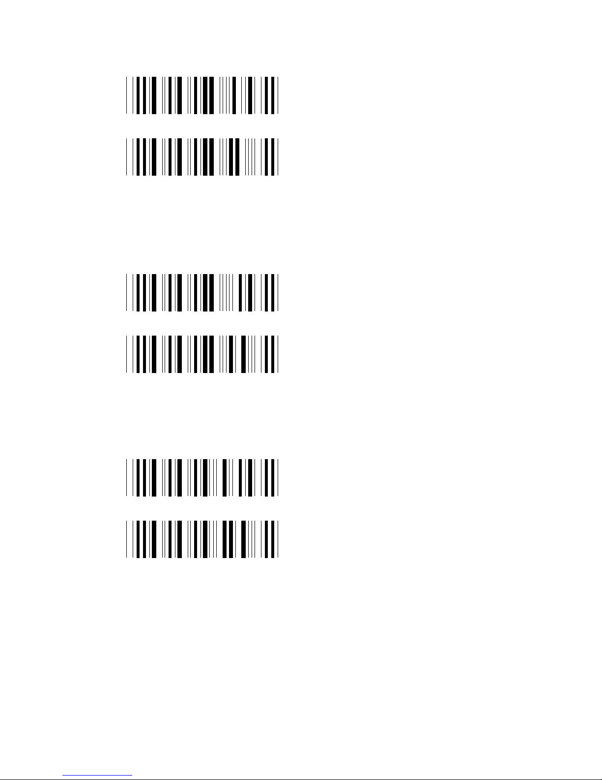
32
KBD-WEDGE PARAMETERS
Function codes
OFF
ON*
Upper / Lower case
LOWER CASE
UPPER CASE*
Num-lock emulation
OFF*
ON
Page 34

33
Keyboard language
USA*
U.K.
SWISS
SWEDISH
SPANISH
NORWEGIAN
ITALIAN
GERMAN
FRENCH
Page 35

34
BARCODE LENGTH PARAMETER
Barcode Fixed length
SET MAX&MIN
CODE-39 (1-64)
I 2/5 (4-64)
S 2/5 (4-64)
CODE-128 (4-64)
MSI (4-16)
CODE-93 (4-64)
CODE-11 (4-64)
CODABAR (4-64)
MAX ( MM )
MIN ( NN )
Page 36
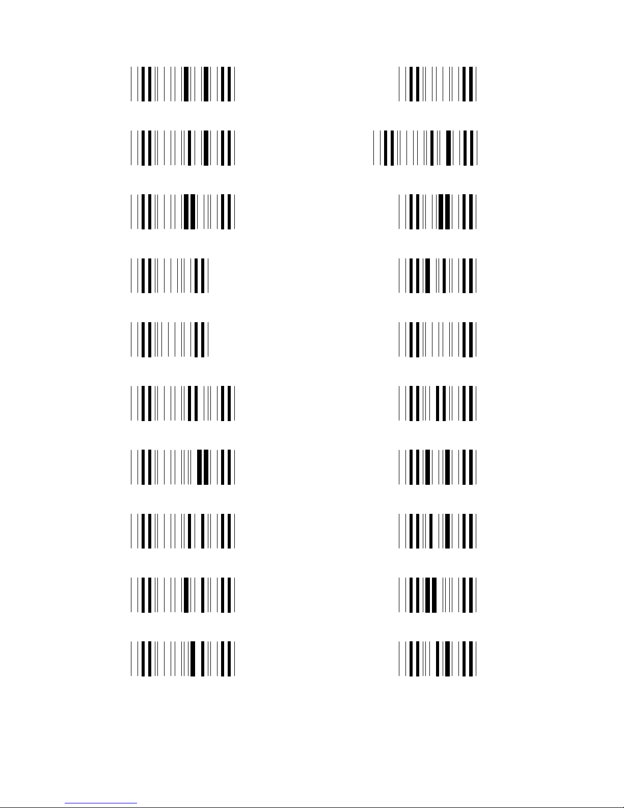
35
ASCII TABLE
!
"
#
,
&
(
)
*
'
$
+
-
.
/
0
1
2
3
4
%
Page 37
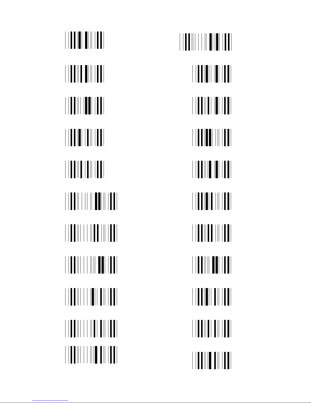
36
ASCII TABLE
=
@
A
B
C
D
E
F
G
H
I
6
7
8
9
5
:
;
<
=
>
?
J
Page 38
37
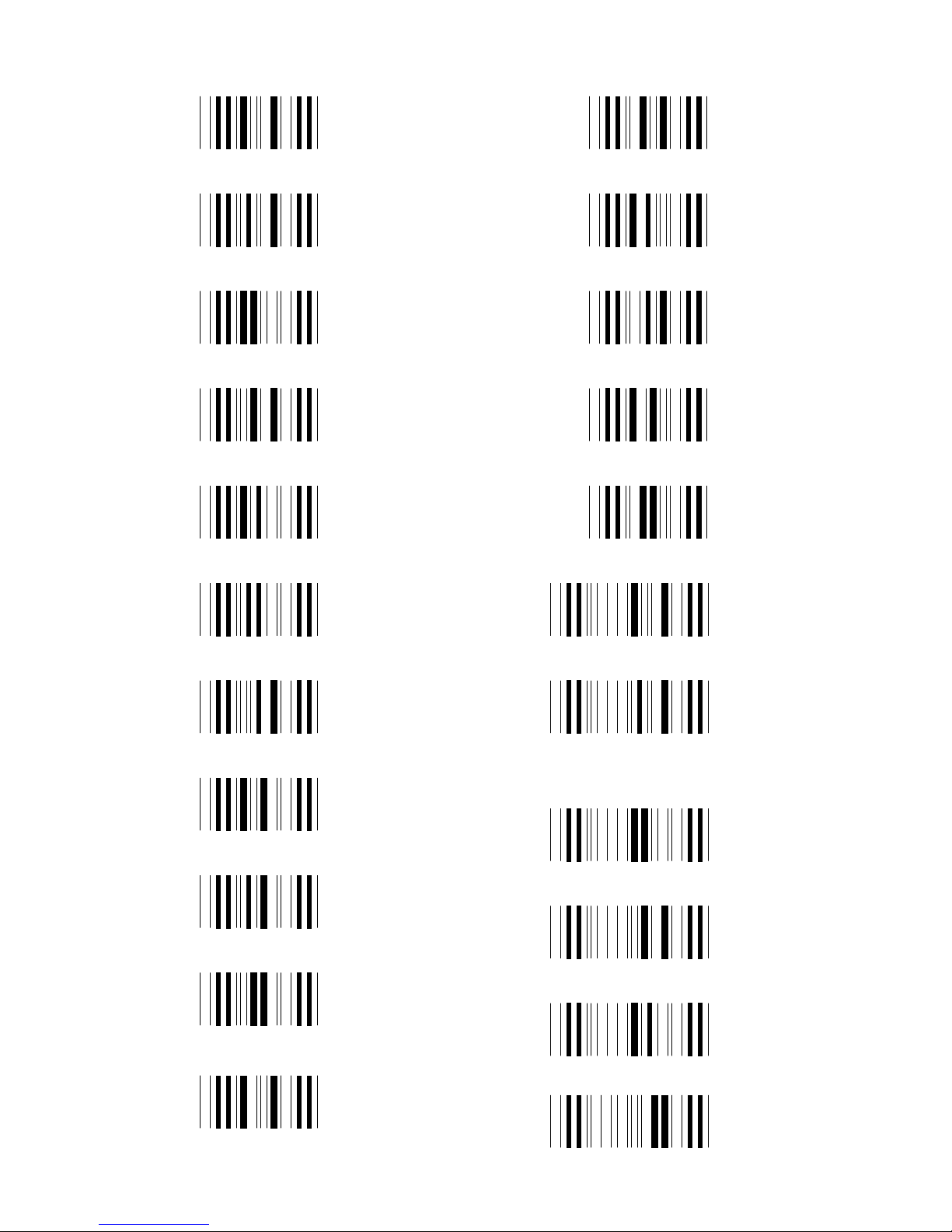
ASCII TABLE
K
L
M
N
O
P
Q
R
S
T
V
W
X
Y
Z
[
\
]
^
_
U
'
Page 39
38
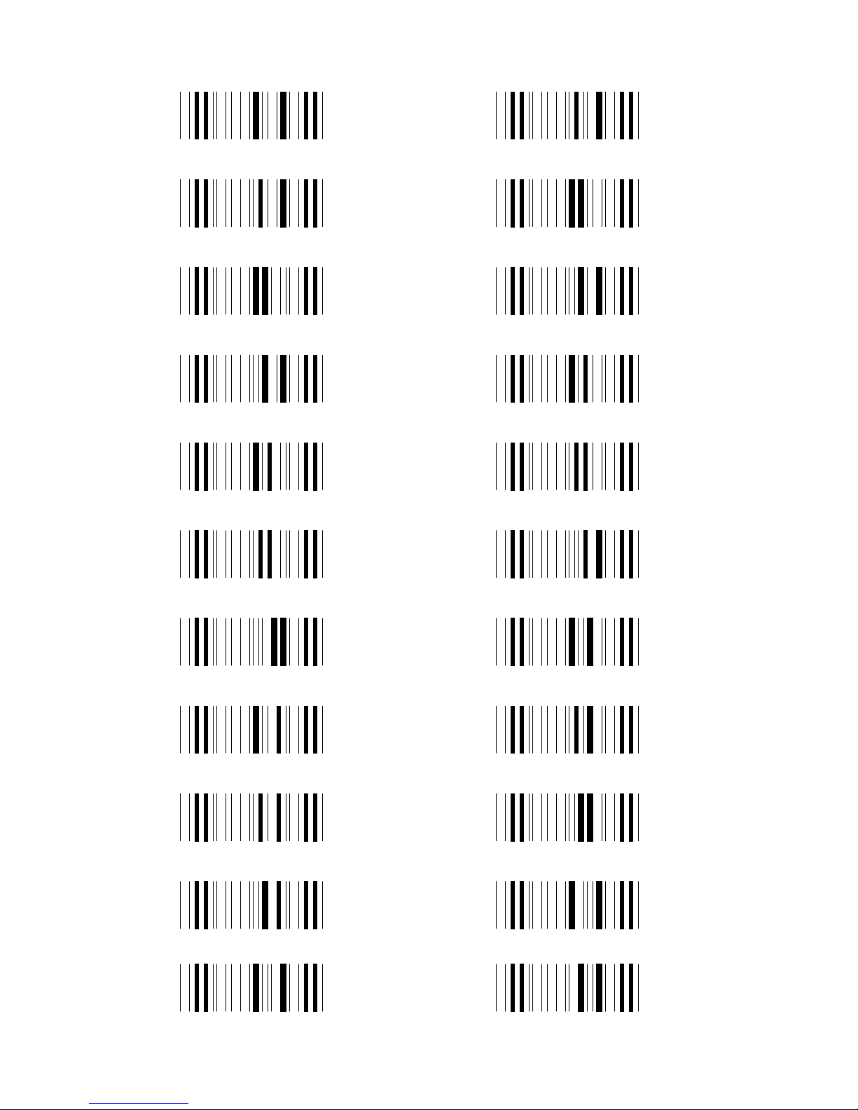
ASCII TABLE
a
b
c
d
e
f
g
h
i
j
l
m
n
o
p
q
r
s
t
u
k v
Page 40
39
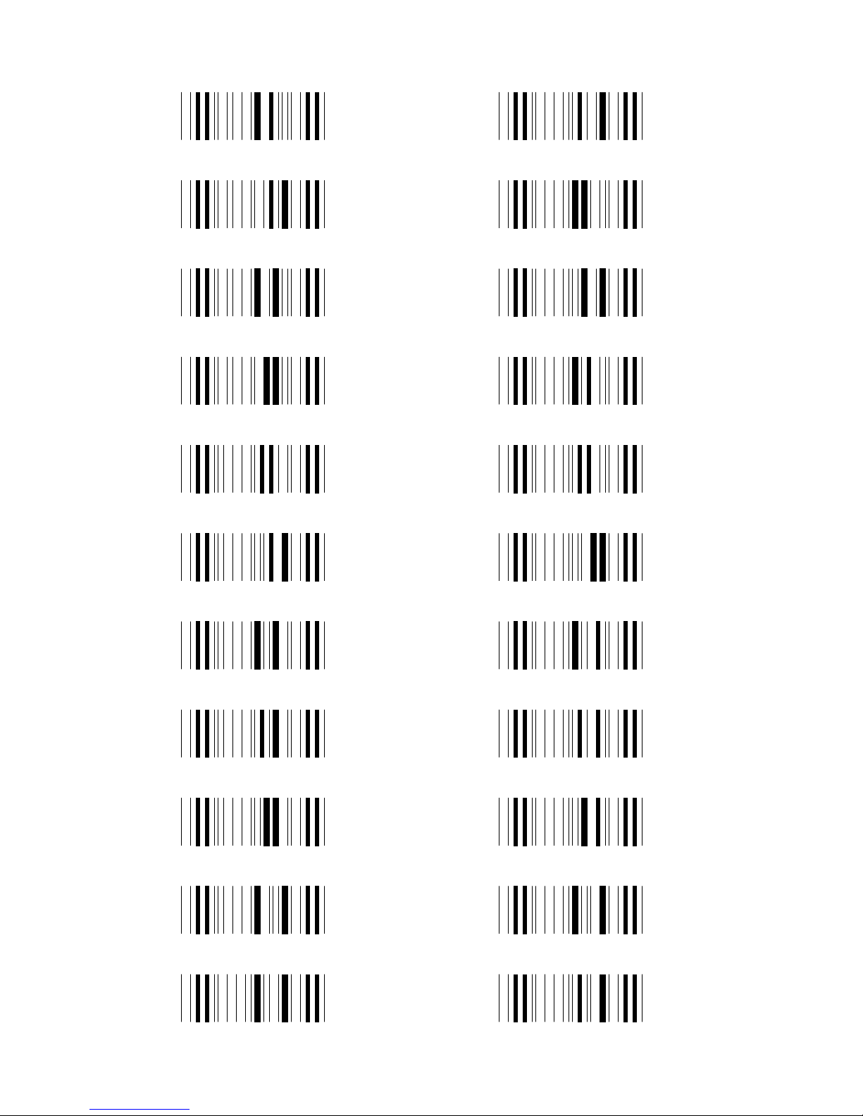
ASCII TABLE
w
x
y
z
{
|
}
~
DEL
NUL
STX
ETX
EOT
ENQ
ACK
BEL
BS
HT
LF
VT
FFSOH
Page 41
40
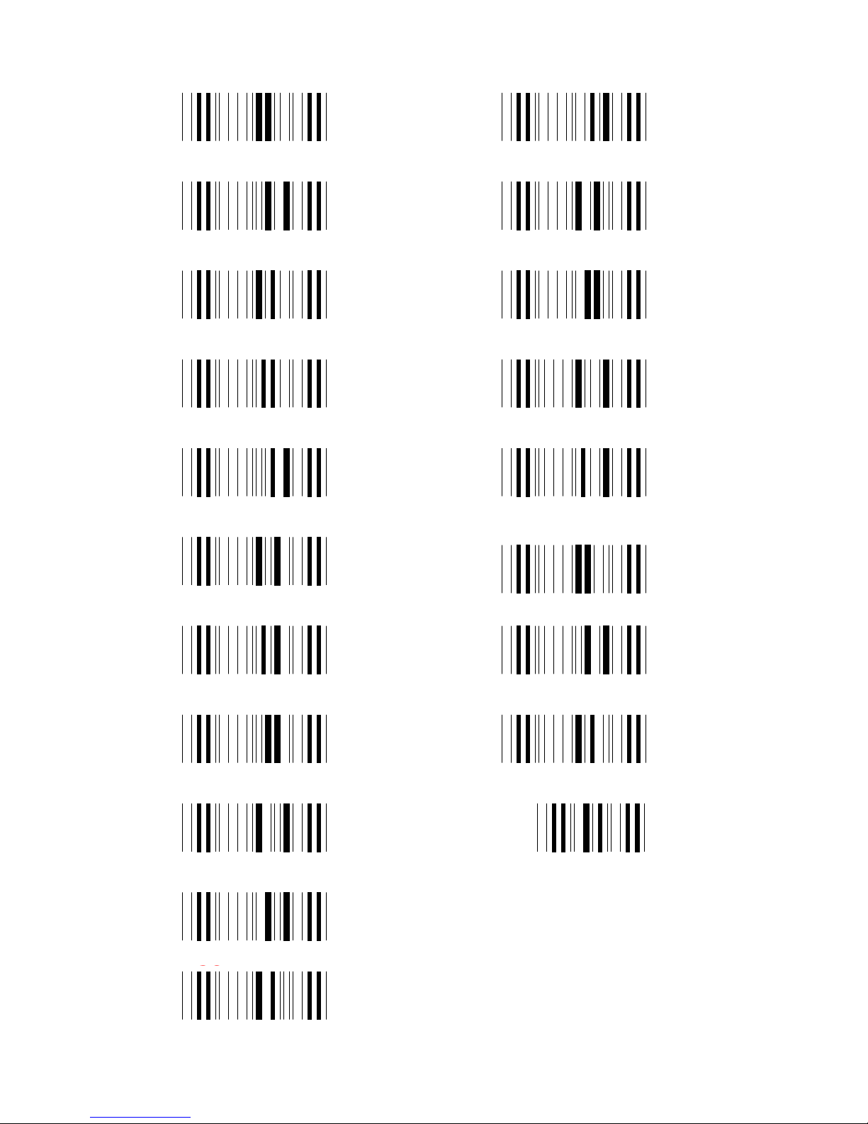
ASCII TABLE
ASCII TABLE
CR
SO
SI
DLE
DC1
DC2
DC3
DC4
NAK
SYN
CAN
EM
SUB
ESC
FS
RS
US
SP
GS
ETB
Page 42
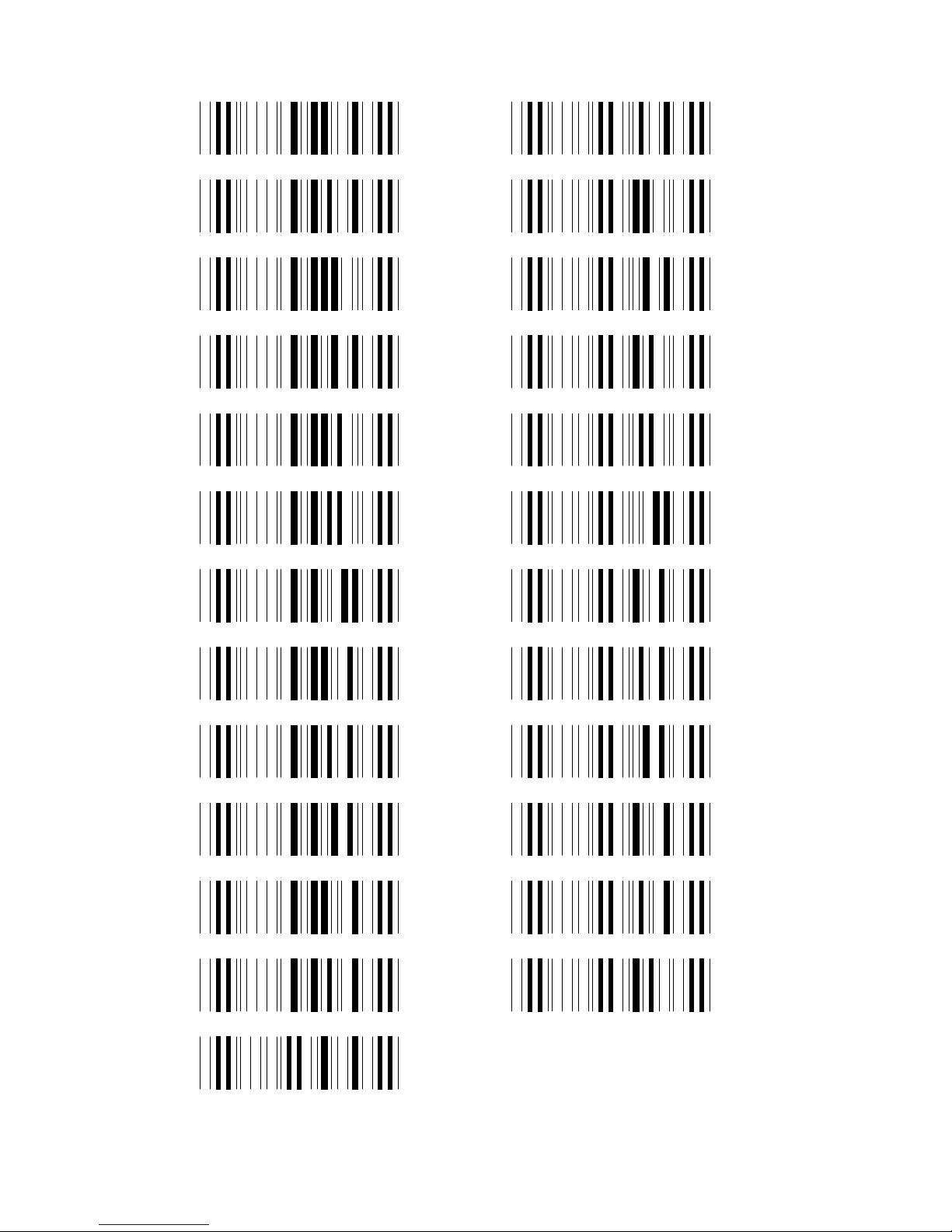
41
ASCII TABLE
F1
F2
F3
F4
F5
F6
F7
F8
F9
F10
F11
F12
HOME
END
CURSOR RIGHT
CURSOR LEFT
CURSOR UP
CURSOR DOWN
PAGE UP
PAGE DOWN
TAB
BACK TAB
ESC
ENTER
RIGHT CTRL
Page 43

42
http://www.barcodeyes.com
 Loading...