

Page 1

MVM
INSTALLATION MANUAL
FOR
CHEVROLET - UPLANDER - 2005-2007
PONTIAC - MONTANA - 2005-2007
BUICK - TERRAZA - 2005-2007
SATURN - RELAY - 2005-2007
Mount Location: To the Right of the Climate Control
Multi Vehicle Mount
MVM-15-05
Includes PHS-203 Ultra Slim Swivel
bracket for most all mobile electronics requiring a steady and secure installation in a mo-
tor vehicle. The MVM installs behind your vehicles dash panel using existing or non-vis-
Before installing, you must take the time to read and understand this installation manual
Thank you for purchasing your new Bracketron MVM Multi Vehicle Mount.
The Multi Vehicle Mount is an (end user-installer) modifi able professional mounting
ible holes and is designed to cleanly protrude out from your vehicle’s dash panel.
and read all the warnings accompanying this product.
Instructions Include: tools needed for install, directions for dash panel removal, directions
for modifying the MVM if required.
You can download this manual and any updates from
http://www.bracketron.com/downloads
Page 2
IMPORTANT INFORMATION
••••••••••••••••••••••••••••••••••••••••••••••••••••••••••••••••••••••••••••••••••••••••••••••••••••
IMPORTANT INFORMATION
Please read instructions completely before installing this Bracketron MVM Mount. All instructions are written from the drivers
seat vantage point looking forward at the vehicles dash. We advise caution whenever you are removing or handling plastic
parts of a vehicles dash. WARNING: Unnecessary force or pressure can cause pieces to crack or break.
PARTS INCLUDED: MVM-15-05 Mount, 3- #8x3/4” Self Tapping Screws PHS-203 Ultra Slim Swivel, and Hardware
Page 1
MVM Instructions |
TOOLS NEEDED FOR DASH PANEL DISASSEMBLY
Dash Trim Tool (Part #SIT-104)
7mm Socket and Driver
9/32” Open End Wrench (for swivel)
#2 Phillips Screwdriver
TOOLS NEEDED FOR MVM MODIFICATION (if required)
4 inch Mounted Bench Vise
12 oz. Ball Pein Hammer
Standard Tin Snips
Small File
Note: The hole pattern on the face of the MVM maybe
different then what is shown in the pictures.
DASH DISASSEMBLY INSTRUCTION
••••••••••••••••••••••••••••••••••••••••••••••••••••••••••••••••••••••••••••••••••••••••••••••••••••
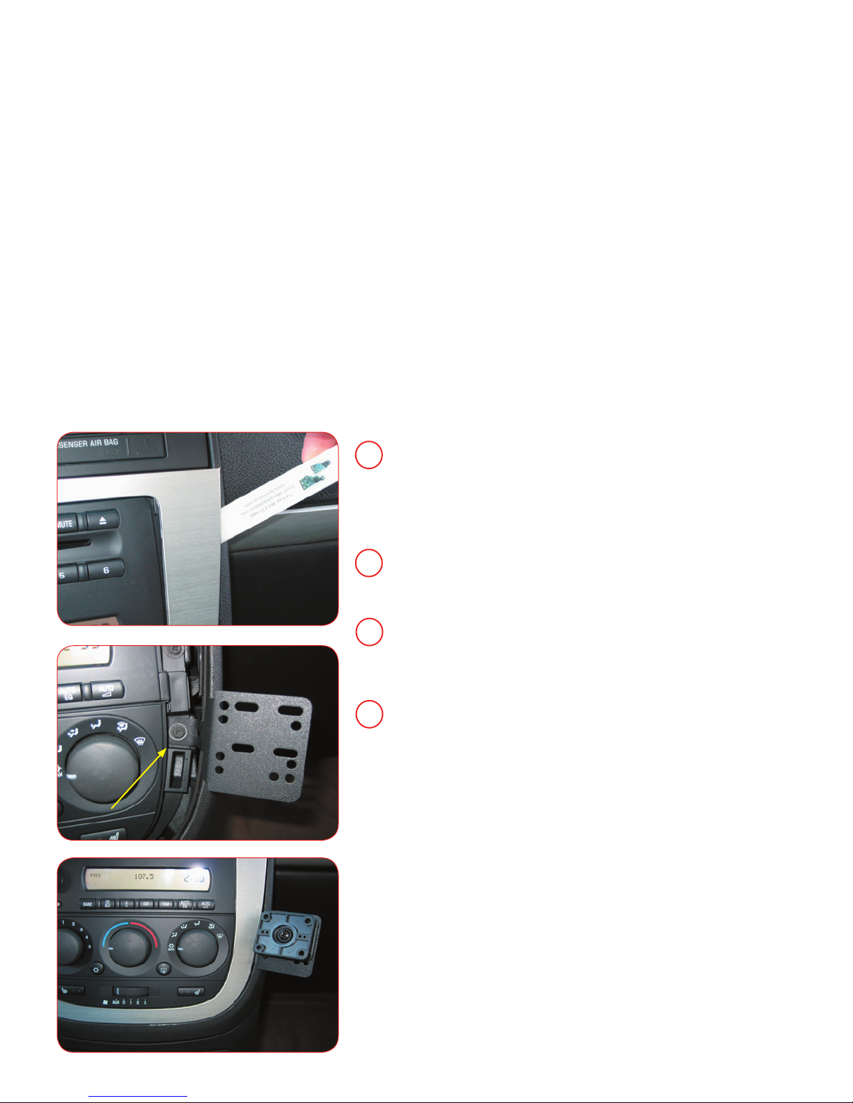
Begin installation by removing the bezel that surrounds the radio and climate
1
control. There are 5 metal retainer clips around the perimeter and 3 plastic
clips near the top that secure this bezel. When bezel is removed, set it aside
carefully.
Skip to Step 5 on the following page if you have not yet formed the bracket
2
to fit your vehicle.
With a Phillips screwdriver (or 7mm socket and driver), locate and remove
3
the screw directly to the right side of the climate control. Set the screw aside.
Place the MVM over the screw hole and replace factory screw. Note: Make
sure the MVM is resting tightly against the right side of the dash bezel
Install Mount Here
Carefully reinstall the dash in reverse order securing the dash bezel into its
4
original position. Note: You will feel and hear a “click” when all 8 clips are
secured.
If Desired, Install the included Ultra Slim Swivel #PHS-203 to your Multi
Vehicle Mount or any other AMPs compatible device.
Your installation is complete
Page 3
MVM MODIFICATION INSTRUCTIONS
••••••••••••••••••••••••••••••••••••••••••••••••••••••••••••••••••••••••••••••••••••••••••••••••••••
PLEASE NOTE
The Bracketron MVM-15-05 mount is a modifi able mounting bracket. The illustrations on the left show how this mount should
look during and after the modifi cation steps in order to fi t the listed vehicles on the front page of this manual.
applications may not require any modifi cations to the mount. If this is the case it will be noted below and there will be no steps
to follow on this page.
Many vehicle
Page 2
MVM Instructions |
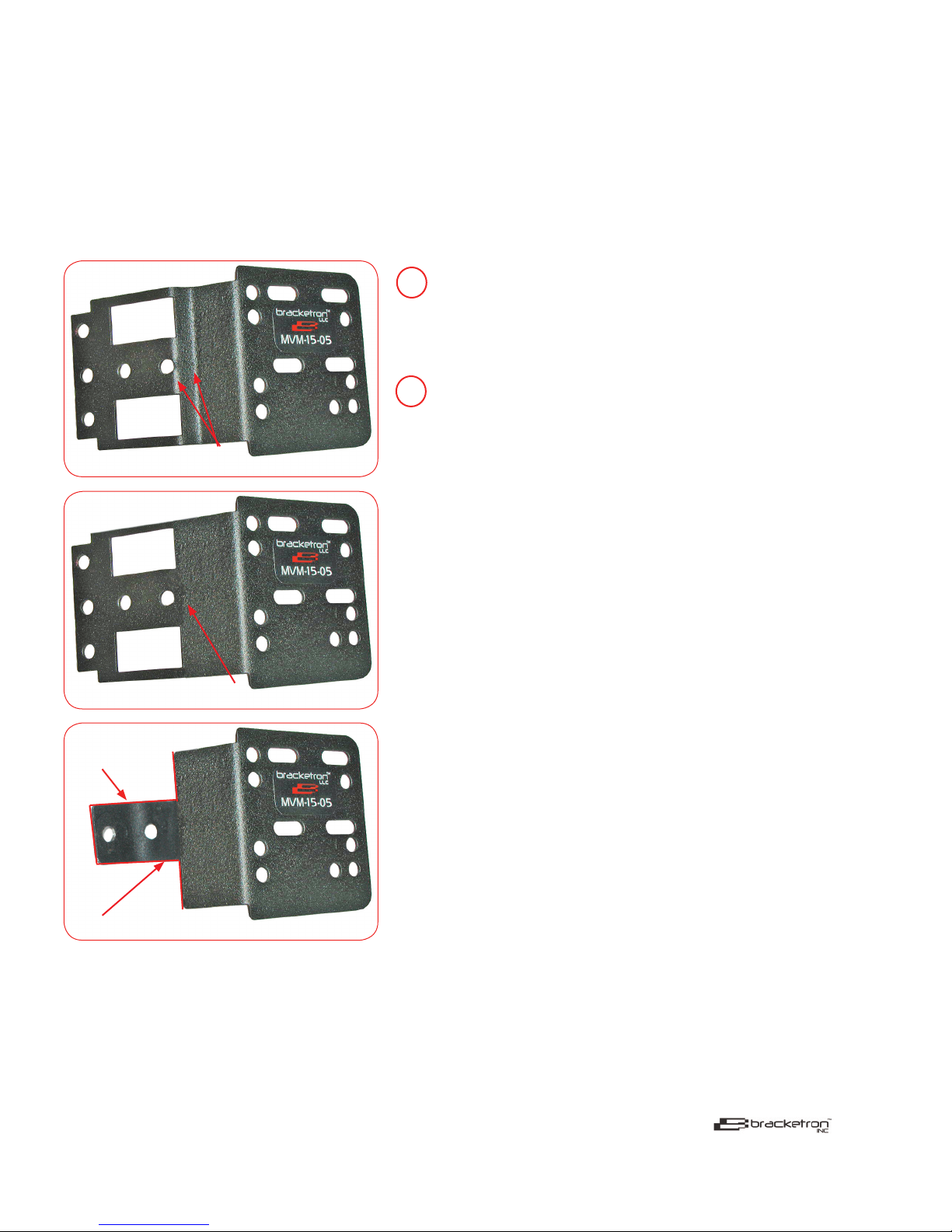
Picture 1
Existing Bends
Picture 2
Flatten Mount Here
To modify the MVM, start by fl attening the existing bends shown in
5
picture 1 on the left. Place the MVM on the fl at spot of the bench vise and
pound out the bends until the MVM is fl at and looks like picture 2 on the
left.
Use the tin snips to cut away the parts of the mount that are not needed
6
as shown in Picture 3 on the left. Once the MVM is cut, bend the remaining tab into a 90 degree angle. The bend does not need to be a sharpe
90 degree bend, it just has to bend enough to allow you to mount it using
the exsiting screw hole as shown on page 1.
Return to step 3 on page 1.
Note: Please see page 3 in this manual for PHS-
203 Ultra Slim Swivel Instructions.
Picture 3
Bend Mount
Cut On Red Lines
Note: The hole pattern on the face of the
MVM maybe different then what is shown in
the pictures.
© Bracketron Inc, 2007 All rights reserved.
The information in this document is subject to change without notice. Bracketron Inc. assumes no responsibility for any errors that may appear in this document nor
do we assume any liability in connection with its use. This supersedes and voids all previous literature. Please contact the sales department for additional information.
Bracketron Inc will not be responsible or liable for damage to vehicles in the installation and or removal of this Bracketron Inc mount. Bracketron Inc will not be liable
for personal injuries or damage to property resulting from a motor vehicle accident and or improper installation of this Bracketron Inc mount.
Bracketron Inc 5249 West 73rd Street, Suite G, Edina, MN 55439
tel: 952-746-7775 fax: 1-800-660-1784 toll free: 1-866-237-4443
email: [email protected] web: www.bracketron.com
Page 4
PHS-203 ULTRA SLIM SWIVEL INSTRUCTIONS
••••••••••••••••••••••••••••••••••••••••••••••••••••••••••••••••••••••••••••••••••••••••••••••••••••
PLEASE READ INSTRUCTIONS COMPLETELY BEFORE INSTALLING THIS BRACKETRON MOBILE SOLUTION.
Page 3
This Professional Swivel Mount Solution is designed to be mounted to your MVM or any other 4 hole AMPs compatible mounting
device. The Ultra Slim Swivel is compact with a low profi le and is designed to provide adjustability to devices such as Satellite
Radio Receivers, GPS monitors or Mobile Phones. The Ultra Slim Swivel angles your device for better viewing, tilting approx 15°
in all directions and swivels 360° degrees for maximum adjustability. All mounting hardware is included in the kit along with our
AMPs adapter plate to attach devices that support T- Notch mounting.
PARTS INCLUDED
1 - Ultra Slim Swivel
1 - AMPs Adapter Plate
4 - M4 x 10 Hex Head
Screws
4 - M4 x 10 Pan Head Screws
4 - M4 x 12 Pan Head Screws
4 - M4 Hex Head Nuts
4 - M4 Nylon Locking Nuts
Note: The swivel can be installed before or after the mount is installed
1
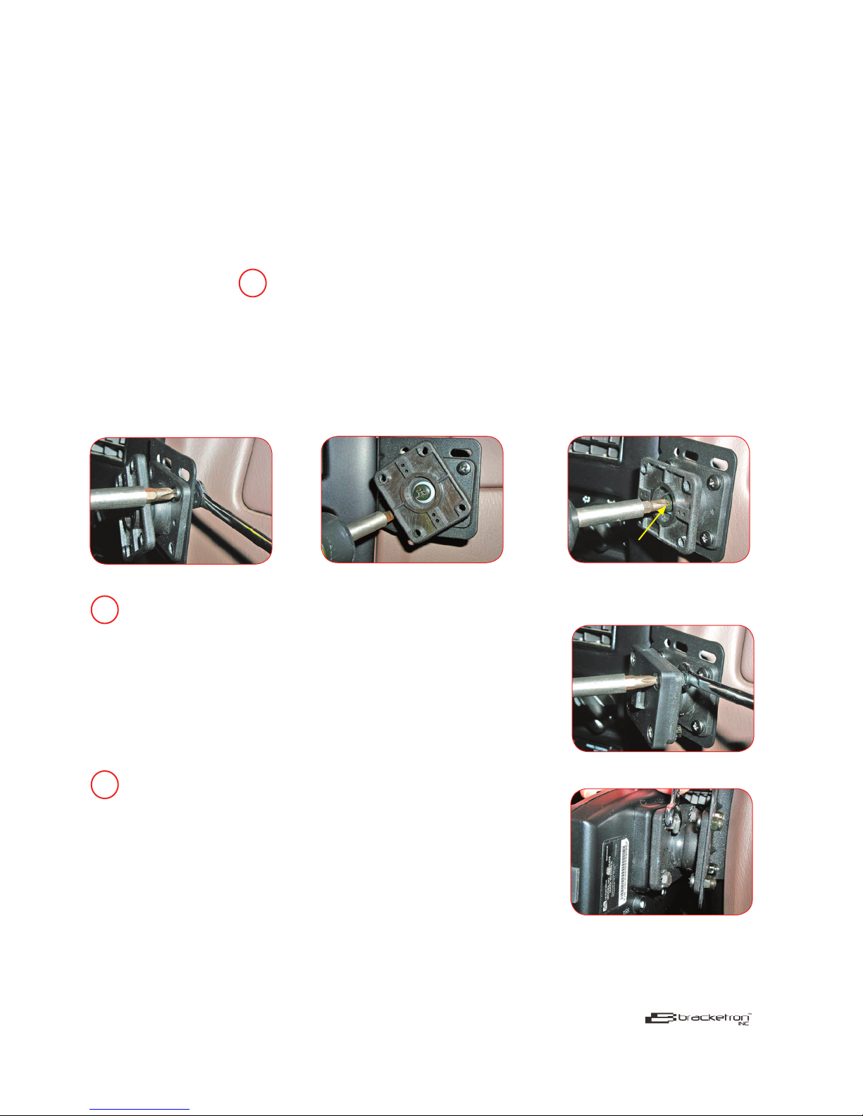
in the vehicle. Attach the Ultra Slim Swivel to any MVM or CBM Mount or other AMPs
mounting device by inserting the M4x10 Pan Head screws through the holes on the
back half of the swivel. Align the screws up with the holes on the mount. Attach the M4
Nylon Locking Nuts only fi nger tight. Rotate the front half of the swivel to gain access to
the M4x10 Pan Head screws. (See Picture 1&2) Tighten all 4 screws with a #2 Phillips
screwdriver and 9/32” open end wrench.
4 - M4 Star Washers
Picture 1
Rotate
Picture 2
Rotate
Picture 3
Adjust Hold Tension
MVM Instructions |
Tighten the center screw to adjust the desired tension of the swivel. (See
2
Picture 3) Note: If Swivel becomes loose over time, you can grasp the
swivel and pull toward you lightly while rotating it clockwise. This will
tighten the swivel allowing you to create the desired tension needed.
For T- Notch Devices
Attach the AMPs T- Notch Adapter to the front half of the swivel
using the M4x12 Pan Head screws. Attach the M4 Star Washers and
M4 Hex Nuts to the screws and tighten the plate down with the #2
screwdriver and 9/32” open end wrench. Slide your device onto the
T- notch Adapter plate to secure it to the swivel. (See Pictures 4)
3
For AMPs Devices with Inserts
Attach your AMPs device using the M4x10 Hex Head screws and M4
Star Washers. Align the holes on the device with the holes on the front
half of the swivel. Slide the Star Washers onto the Hex Head screws.
Insert the screws through the swivel and into your device only fi nger
tight. Tighten down the device with the 9/32” open end wrench.
Your device is now secure to the swivel. (See Pictures 5)
Picture 4
Picture 5
© Bracketron Inc, 2007 All rights reserved.
The information in this document is subject to change without notice. Bracketron Inc. assumes no responsibility for any errors that may appear in this document nor
do we assume any liability in connection with its use. This supersedes and voids all previous literature. Please contact the sales department for additional information.
Bracketron Inc will not be responsible or liable for damage to vehicles in the installation and or removal of this Bracketron Inc mount. Bracketron Inc will not be liable
for personal injuries or damage to property resulting from a motor vehicle accident and or improper installation of this Bracketron Inc mount.
Bracketron Inc 5249 West 73rd Street, Suite G, Edina, MN 55439
tel: 952-746-7775 fax: 1-800-660-1784 toll free: 1-866-237-4443
email: [email protected] web: www.bracketron.com
 Loading...