

Page 1

PROVIT 3030
USER'S MANUAL
Version: 1.0 (April 1992)
Model No.: 6F0001.00-020
ARCNET is a registered trademark of Datapoint Corp.
MS-DOS is a registered trademark of Microsoft Corp.
IBM is a registered trademark of International Business Machines Corp.
1
Page 2

2
Page 3

CONTENTS
3
Page 4

CONTENTS
1. General Information................................................................................................................................... 7
1.1 General Information.................................................................................................................... 9
1.2 MS-DOS ................................................................................................................................... 10
1.3 Documentation ......................................................................................................................... 10
1.4 Technical Data.......................................................................................................................... 11
2. Install Procedures ................................................................................................................................... 13
2.1 Unpacking ....................................................................................................................................... 15
2.2 Checking the Delivery ..................................................................................................................... 15
2.3 Before Power-on ............................................................................................................................. 16
2.3.1 AC Input Voltage Switch ....................................................................................................... 16
2.3.2 Power Cable .......................................................................................................................... 16
2.3.3 Transport Safety .................................................................................................................... 17
2.3.4 Hand Screws ......................................................................................................................... 17
2.3.5 Fan......................................................................................................................................... 18
2.3.6 Potentiometer Gain Control Knob ......................................................................................... 18
2.3.7 Terminal Block....................................................................................................................... 18
3. Installation ............................................................................................................................................... 19
3.1 Structure.......................................................................................................................................... 21
3.2 Computer Module ........................................................................................................................... 22
3.2.1 Removal................................................................................................................................. 22
3.2.2 Installation ............................................................................................................................. 22
3.2.3 Board Installation................................................................................................................... 23
3.3 Monitor Module ............................................................................................................................... 24
3.3.1 Removal................................................................................................................................. 24
3.3.2 Installation ............................................................................................................................. 25
3.4 Housing ........................................................................................................................................... 26
3.4.1 Housing Gasket ..................................................................................................................... 26
3.4.2 19" Rack Installation.............................................................................................................. 27
3.4.3 Wall Installation ..................................................................................................................... 28
3.4.4 Screw Covers ........................................................................................................................ 29
3.4.5 Air Circulation ........................................................................................................................ 29
4. Device Description .................................................................................................................................. 31
4.1 General............................................................................................................................................ 33
4.1.1 Memory.................................................................................................................................. 33
4.2 Front View ....................................................................................................................................... 33
4.2.1 Floppy Disk Drive .................................................................................................................. 34
4.2.2 Hard Disk Drive ..................................................................................................................... 34
4.2.3 Monitor ................................................................................................................................... 35
4.2.4 Keyboard ............................................................................................................................... 35
4.2.5 Keyboard Legend .................................................................................................................. 36
4.2.6 Key LEDs............................................................................................................................... 36
4.2.7 Status LEDs .......................................................................................................................... 36
4.2.8 Reset Button.......................................................................................................................... 36
4.3 Computer Module ........................................................................................................................... 37
4.3.1 Slots....................................................................................................................................... 37
4.3.2 Monitor Connection ............................................................................................................... 37
4.3.3 Serial Interfaces .................................................................................................................... 38
4
Page 5

4.3.4 Parallel Printer Interface........................................................................................................ 38
4.3.5 Keyboard Interface ................................................................................................................ 38
4.3.6 I/O Port .................................................................................................................................. 38
4.3.7 24 VDC Output ...................................................................................................................... 38
4.3.8 Fan......................................................................................................................................... 39
4.4 Monitor Module ............................................................................................................................... 40
4.4.1 Fuses ..................................................................................................................................... 40
4.4.2 Voltage Selection Switch ....................................................................................................... 40
4.4.3 Power Connection ................................................................................................................. 40
4.4.4 Monitor Settings .................................................................................................................... 41
4.4.5 Ground Connection ............................................................................................................... 41
5. Software .................................................................................................................................................. 43
5.1 B&R Utility Diskette......................................................................................................................... 45
5.2 I/O Ports .......................................................................................................................................... 45
5.2.1 Key LEDs............................................................................................................................... 46
5.2.2 User LED ............................................................................................................................... 47
5.2.3 Digital Inputs.......................................................................................................................... 47
5.2.4 Relay Outputs........................................................................................................................ 47
5.2.5 Temperature Monitoring ........................................................................................................ 48
5.3 Addresses and Interrupts ............................................................................................................... 49
5.3.1 Addresses .............................................................................................................................. 49
5.3.2 Interrupts ............................................................................................................................... 49
6. Options and Replacements..................................................................................................................... 51
6.1 Keyboard Case ............................................................................................................................... 53
6.2 RS232 Interface card ...................................................................................................................... 53
6.3 CPU Cards ...................................................................................................................................... 53
6.4 VGA Card ........................................................................................................................................ 54
6.5 Memory Expansion ......................................................................................................................... 54
6.6 Interface Module for PLC Programming ......................................................................................... 54
6.7 CENTRONICS/On-line Converter................................................................................................... 54
6.8 Replacement Parts ......................................................................................................................... 55
B&R Sales and Service ............................................................................................................................... 57
Index 61
5
Page 6

6
Page 7

SECTION 1
GENERAL INFORMATION
7
Page 8

8
Page 9

1.1 GENERAL INFORMATION
New standards have been set in the areas of industrial quality, flexibility and functionality with the PROVIT
3030 industrial PC.
Quality:
- Front is dust and water proof to IP54 standards (IP65 standards are in development)
- Soft rubber mounted hard disk for shock absorption
- High temperature range, software controlled temperature monitoring
- All boards solidly screw mounted (with board fasteners)
- Two electrically isolated RS232 interfaces
Functionality:
- High resolution 14" color monitor with scratch resistant, glare free screen
- CPU either 286 (16 MHz), 386 SX (25 MHz) or 386 DX (33 MHz, 64 KB Cache)
- Working memory 2 MB (286, 386 SX) or 4 MB (386 DX) RAM, expandible to 16 MB
- 52 MB hard disk
- 3.5" floppy disk drive, 1.44 MB
- MS-DOS 5.0, English or German
- Parallel printer port
- Four RS232 interface ports
- External keyboard port
- Five relay outputs, four 24 VDC inputs
- Matrix keyboard and function keys with key LEDs
- User keys can be labelled with insertable plastic strips
Flexibility:
- 19" frame for easy mount in a rack or in the wall
- Two bus slots for user specific boards
- No tools are required for exchanging PC or monitor components
- External keyboard is available with or without IP54 standards keyboard case
- Optional ARCNET or Profibus network card
9
Page 10

1.2 MS-DOS
PROVIT 3030 industrial PC comes with MS-DOS 5.0 in English or German. MS-DOS is delivered in its original
package. To date the PROVIT 3030 has MS-DOS 5.0 installed on drive C in English. If a user requires the
German version it can be easily installed (see the MS-DOS User's Manual, "Replacing an installed MS-DOS
version).
1.3 DOCUMENTATION
The following documentation is delivered with the PROVIT 3030:
- PROVIT 3030 industrial PC User's Manual
- CPU card user's manual
- VGA card user's manual
- RS232 interface card user's manual
- MS-DOS 5.0 user's manual
Manuals for the CPU and VGA cards are provided by the manufacturer. If necessary B&R includes updates
with any additional information required.
10
Page 11
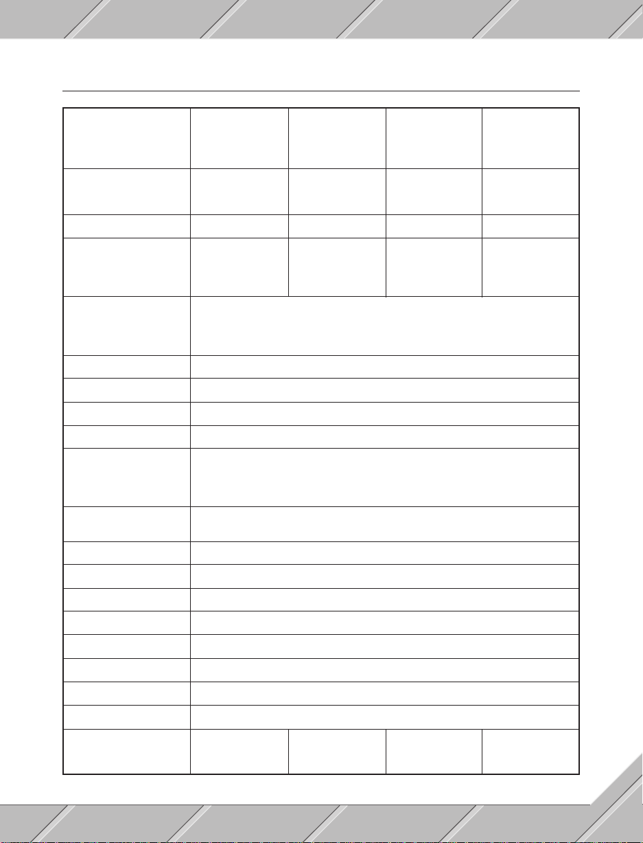
1.4 TECHNICAL DATA
Processor
Type 80286 80386 SX 80386 DX 80486
Clock frequency 16 MHz 25 MHz 33 MHz 33 MHz
Cache - - 64 KB 64 KB
Memory
Standard 2 MB 2 MB 4 MB 4 MB
Expandible to 4 MB 16 MB 16 MB 16 MB
Floppy disk drive 3.5" / 1.44 MB 3.5" / 1.44 MB 3.5" / 1.44 MB 3.5" / 1.44 MB
Hard disk drive
Capacity 52 MB 52 MB 52 MB 105 MB
Cache 64 KB 64 KB 64 KB 64 KB
Average access time 18 msec. 18 msec. 18 msec. 18 msec.
Dimensions
Width 483 mm (19")
Height 310 mm
Depth 450 mm
Protective standard IP54
Mounting 19" frame for rack mount or wall mount
Weight approx.. 28 kg
Power requirements 120 / 220 VAC (47 to 63 Hz), 170 W
Interfaces AT compatible keyboard interface
Parallel printer port (CENTRONICS)
Two isolated RS232 interfaces
Two standard RS232 interfaces
Key pad 12 number keys, 4 cursor keys, 10 illuminated function keys,
16 illuminated user keys
Bus slots Five standard AT bus slots
Monitor High resolution 14" color monitor, VGA graphic card
Digital Inputs Four inputs 24 VDC/AC, input current 10 mA
Digital Outputs Five isolated relays, 48 VAC or 30 VDC (1 A)
Operating system MS-DOS 5.0, German or English
Options Keyboard case, Profibus network card, ARCNET network card
Operating temperature 0 to 50 °C
Humidity 0 to 95 %, without condensation
Model numbers
with German MS-DOS 5B0001.01-110 5B0002.01-110 5B0003.01-110 From July 1992
with English MS-DOS 5B0001.01-120 5B0002.01-120 5B0003.01-120 From July 1992
11
Page 12

12
Page 13

SECTION 2
INSTALL PROCEDURES
13
Page 14

14
Page 15
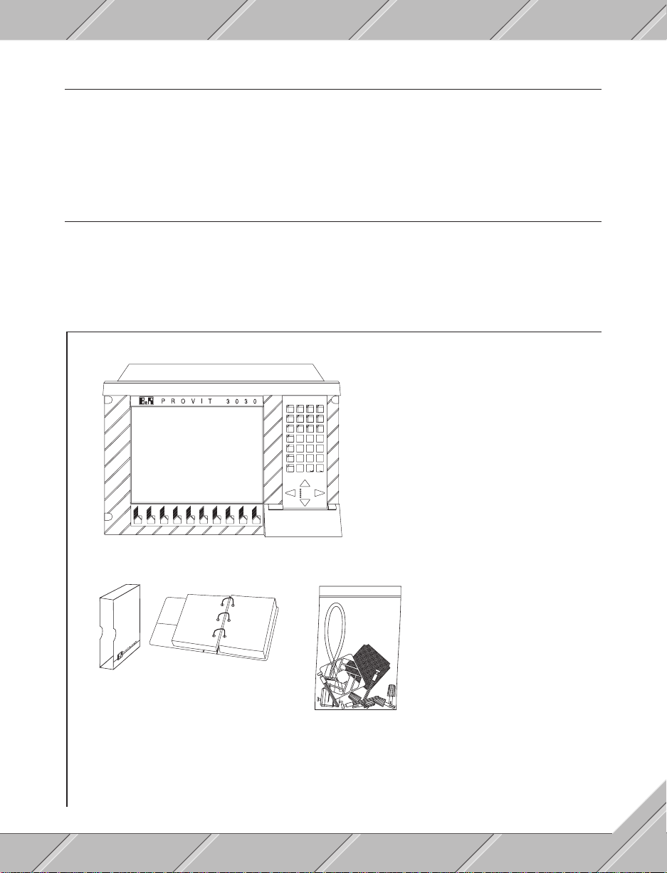
2.1 UNPACKING
1. Open the shipping carton
2. Take out the package with the documentation and utilities inside
3. Remove the PROVIT 3030 together with packing material and place everything on a flat surface
4. Carefully remove all packing material
2.2 CHECKING THE DELIVERY
The material used to package the PROVIT 3030 industrial PC has been tested and is an appropriate safeguard
against any transporting accidents under normal circumstances. If in spite of these measures damages are
noticed, whether to the packing or to the contents, the device may possibly be inoperable. If any damages
are noticed please contact the B&R sales office at once.
Contents of delivery:
PROVIT 3030 INDUSTRIAL PC
Excluding - power cable, fan cover, filter and
7
8
9
4
5
6
2
3
1
0
POWER
HDD
USER
WD
TEMP.
grill, potentiometer control knobs and terminal
blocks; computer and monitor modules are
fixed in place with transport safety screws
F1
F2 F3 F4 F5 F6 F7 F8 F9 F10
DOCUMENTATION AND SOFTWARE
PROVIT 3030 User’s Manual
CPU card User’s Manual
VGA card User’s Manual
RS232 interface card User’s Manual
MS-DOS 5.0, in original package
two diskettes with VGA driver
B&R utility diskette
UTILITIES
Power cable without connector
15 pole terminal block connector
2 pole terminal block connector
Cover for fan unit
Grill for fan unit
Air filter for fan unit
4 screws M6
4 washers M6
4 cage nuts M6
4 nuts M6
4 contact washers M6
4 screw covers
3 board fasteners
4 potentiometer gain control knobs
Housing gasket
5 key-pad label sheets
15
Page 16

2.3 BEFORE POWER-ON
2.3.1 AC INPUT VOLTAGE SWITCH
The PROVIT 3030 industrial PC can operate with single phase alternating current of 120 VAC (USA) or 220
VAC (Europe). Before plugging in and powering-on the voltage switch must be checked for the respective
setting (Section 4 "Device Description" contains more details). The voltage switch can be found at the rear
of the device and is labelled "Voltage Selector". The standard setting for shipping is for a 220 VAC input.
2.3.2 POWER CABLE
The power cable for PROVIT 3030 is included in the scope of delivery. The connection to the device is made
with screw-on connector. The other end is free and can be terminated with a mains plug or direct to a supply
line (section 3 "Installation" and section 4 "Device Description" contain more details).
Attention:
- Only connectors which have protective ground may be used.
- The installation may only be done by qualified personnel.
- Take the precaution of knowing the regulations of electronic installations in your area.
16
Page 17
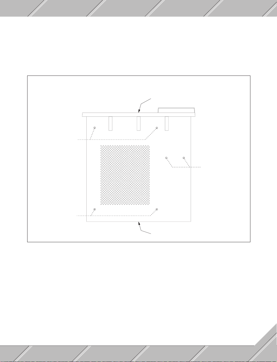
2.3.3 TRANSPORT SAFETY
The PROVIT 3030 industrial PC is constructed of three basic components. A 19" housing, the computer
module and the monitor module. Both modules are fixed in place with easy-on/off hand screws and can be
simply removed without any tools (Section 3 "Installation" contains more details). For delivery purposes the
computer module and the monitor module are held fast with screws in the bottom of the device for transport.
The transport screws are red and must be removed by the user.
TRANSPORT SCREW POSITIONS
(VIEW OF UNDERSIDE)
FRONT
Transport screws for
monitor module
Transport screws for
computer module
Transport screws for
monitor module
REAR
2.3.4 HAND SCREWS
The computer module and the monitor module are bolted in with hand screws. Fastening and removing these
screws is done easily by hand without the need of tools. Before turning on the device be sure that these screws
are secured (Section 3 "Installation" explains more).
17
Page 18

2.3.5 FAN
The fan cover is not installed during transport. Included with the delivery of the PROVIT 3030 is a fan cover,
a grill for the fan and an air filter. The filter must only be used in very dusty or dirty conditions. Fan cover
installation procedure:
- Place the grill inside of the fan cover
- If required the filter is placed in the fan cover as well
- Attach the fan cover over the fan
The PROVIT 3030 Industrial PC may only be operated with the fan cover in place. Air filters are obtainable
at B&R (Section 6 "Options and Replacements" contains more information).
2.3.6 POTENTIOMETER GAIN CONTROL KNOB
Adjusting the monitor is done through the use of four potentiometers which are found on the rear of the PROVIT
3030. The control knobs for these are not attached during transport and must be installed by the user (Section
4 "Device Description" contains more information).
2.3.7 TERMINAL BLOCKS
Terminal blocks for the digital in / outputs and for the 24 VDC supply are not installed during transport. It is
up to the user to attach these to the unit.
18
Page 19

SECTION 3
INSTALLATION
19
Page 20

20
Page 21
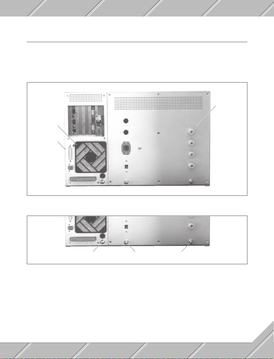
3.1 STRUCTURE
The PROVIT 3030 has a modular structure consisting of:
- Housing
- Computer module
- Monitor module
Monitor module
Computer module
Housing
The computer and monitor module are held in place with hand screws and are easily fastened or unfastened
by hand without the need of tools.
Hand screw for
computer module
Hand screw for monitor module
During transport the device is also held with transport screws which must be removed by the user (Section
2
"Install Procedures" contains more information).
21
Page 22
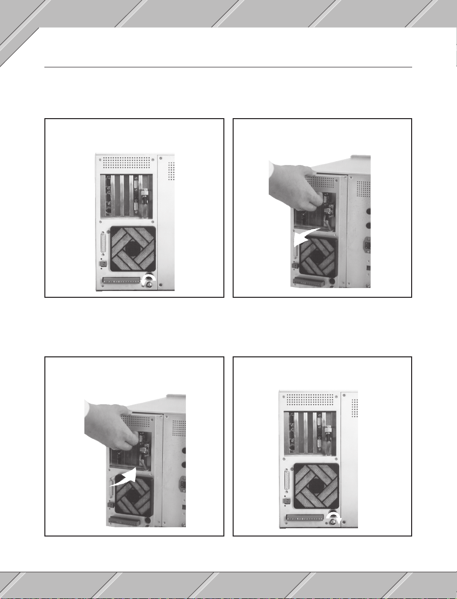
3.2 COMPUTER MODULE
3.2.1 REMOVAL
Before removing the module be sure to pull the power plug. The computer module must always be removed
before the monitor module.
Unfasten the hand screw (turn to the left)
1
3.2.2 INSTALLATION
2
Pull the module out
The computer module may only be installed or replaced when the monitor module is in place.
Insert the computer module and gently push until
1 2
contact is made
1)
Before fastening turn the screw one or two turns to the left.
22
Fasten the hand screw (turn to the right)
1)
Page 23
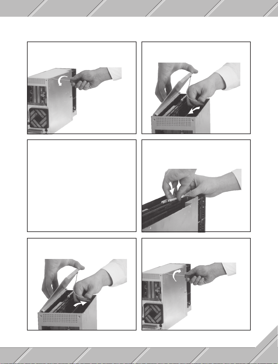
3.2.3 BOARD INSTALLATION
Removes screws from computer module cover
1
(three per side)
3
Remove back cover from slot
Carefully place card in slot with a gentle push and fasten it
4
in place with a fastening screw
Carefully lift computer module cover and remove protective
2
ground cable
5
Longer boards require a board fastener
Reconnect ground cable and replace computer module
6
cover
Replace and fasten all screws for computer module cover
7
(three per side)
23
Page 24
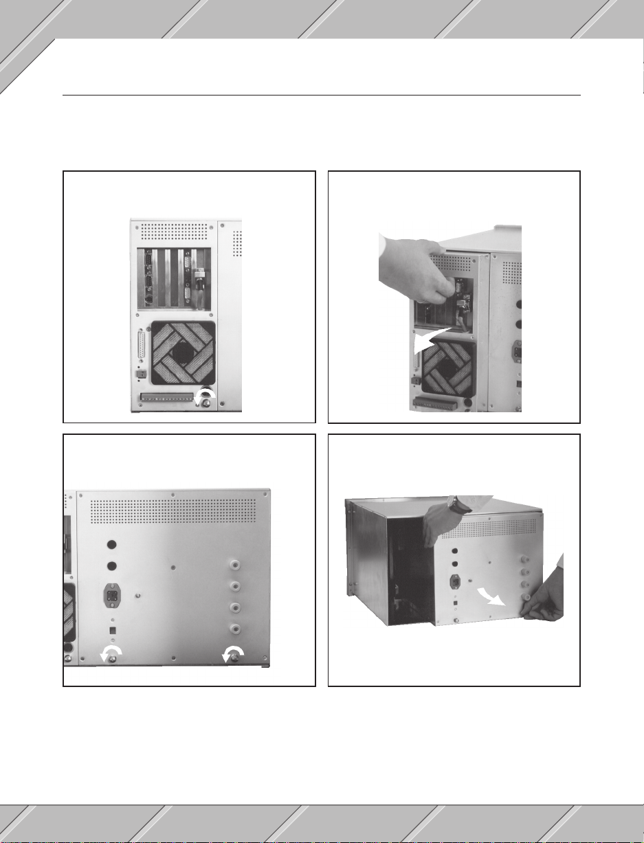
3.3 MONITOR MODULE
3.3.1 REMOVAL
Before removing the monitor module, be sure that the power is disconnected. The monitor module can only
be removed after the computer module is taken out.
Unfasten the computer module hand screws (turn to the left)
1
Remove the computer module
2
3
Unfasten the monitor module hand screws (turn to the left)
24
Remove the monitor module
4
Page 25
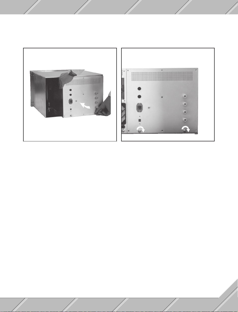
3.3.2 INSTALLATION
The monitor module must be installed before the computer module can be set into place.
Set the monitor module into the housing and gently push in
until it makes contact
1
2 Fasten monitor module hand screws
1)
(turn to the right)
1)
Before fastening the hand screw, turn it one or two times to the left.
25
Page 26
3.4 HOUSING
aaaaaaaaaaaaaaaaaaaaaaaaaaaaaa
aaaaaaaaaaaaaaaaaaaaaaaaaaaaaa
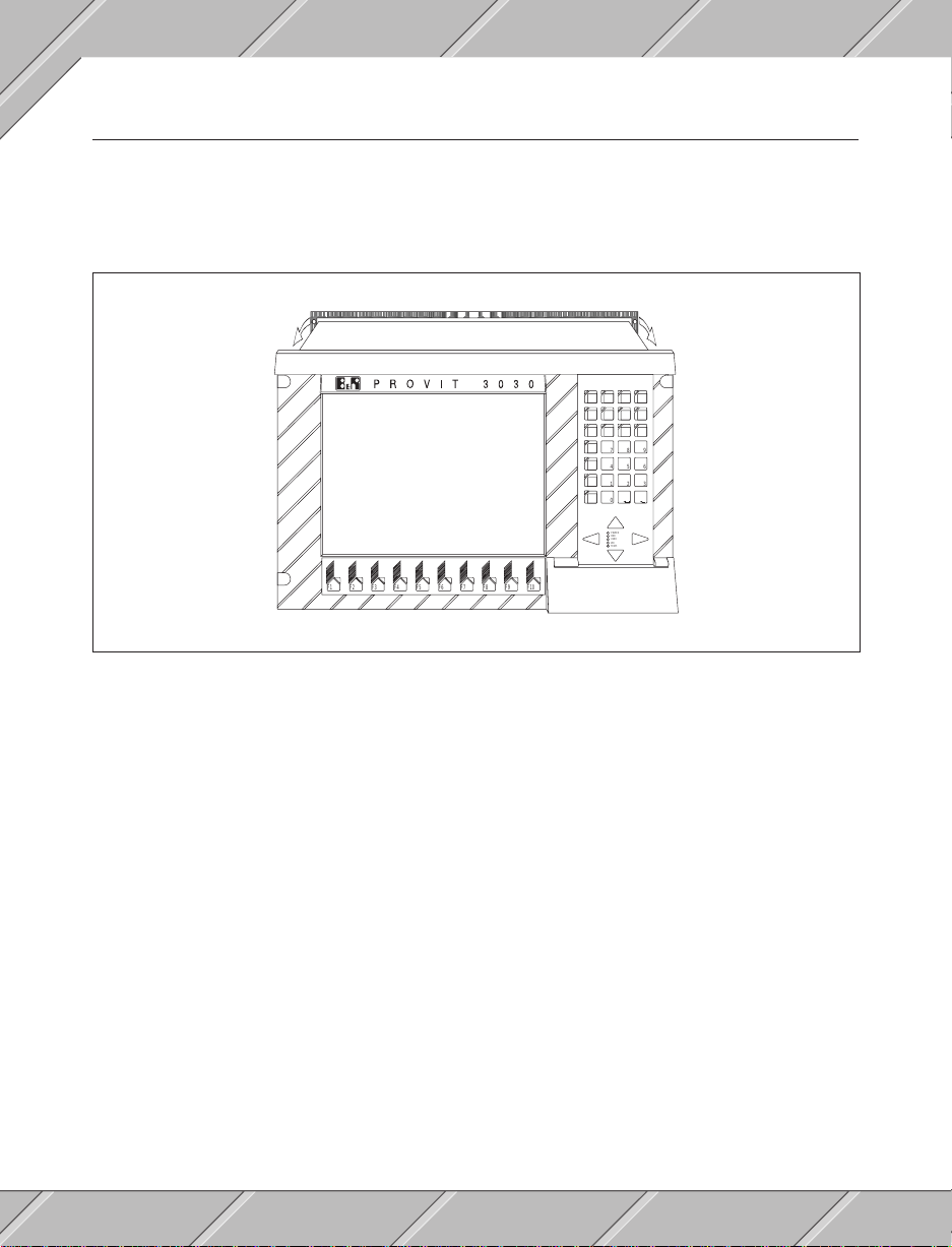
3.4.1 HOUSING GASKET
If the PROVIT 3030 should be installed in dusty or wet areas the gasket which is delivered with the unit must
be in place (e.g. if the unit is installed in a wall). The gasket is slipped over the unit from the rear and moved
up to the front frame.
7
8
9
4
5
6
1
2
3
0
POWER
HDD
USER
WD
TEMP.
F1
F2 F3 F4 F5 F6 F7 F8 F9 F10
26
Page 27
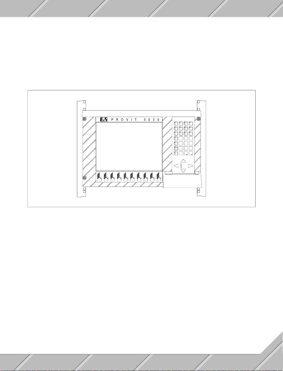
3.4.2 19" RACK INSTALLATION
Before mounting the PROVIT 3030 in a frame the monitor and computer modules should be removed. To
fasten the unit into the rack you will need:
- four M6 screws
- four M6 washers
- four cage nuts
7
8
9
4
5
6
2
3
1
0
POWER
HDD
USER
WD
TEMP.
F1
F2 F3 F4 F5 F6 F7 F8 F9 F10
Installation:
- Insert the cage nuts into the 19" rack in positions respective to holes in the PROVIT 3030 frame
- Remove the monitor and computer modules
- Place the PROVIT 3030 housing in position in the rack
- Using the bolts and washers provided fix the unit to the rack
- Place the screw covers over the screws
- Reinstall the monitor and computer modules
27
Page 28
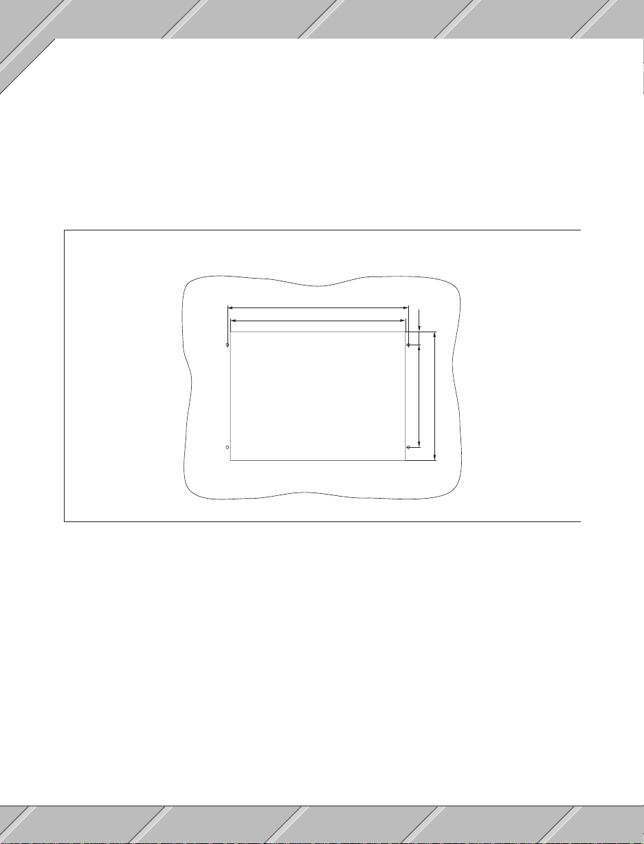
3.4.3 WALL INSTALLATION
Before installing the PROVIT 3030 in the wall remove the monitor and computer modules. To install the unit
in the wall you will need:
- four M6 screws
- four M6 washers
- four contact washers
- four M6 nuts
Be sure that the wall material will hold the 28 kg of the PROVIT 3030.
WALL INSTALLATION
465,1
450
32,3
234,9
297
Installation:
- Cut and drill holes according to the dimensions shown above (all measurements are in millimeters)
- Remove the monitor and computer modules from the housing
- Carefully place the housing into the opening
- Insert the screws with washers through the front of the PROVIT 3030 frame
- Fasten the unit in place with the contact washers and the nuts from the rear
- Put the screw covers in place
- Reinstall the monitor and computer modules
28
Page 29
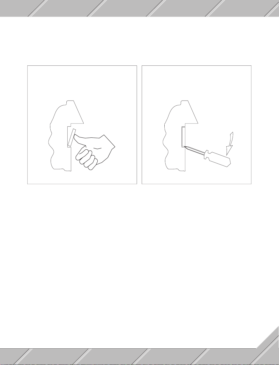
3.4.4 SCREW COVERS
After installing the device four screw covers must be placed over the screws in the frame. The right bottom
screw is found under the floppy disk drive cover.
REPLACING THE SCREW COVERS REMOVING THE SCREW COVERS
Set the cover at a slight angle and with moderate pressure
push until it clicks into place
Place the end of a small screwdriver in the gap between
the cover and the housing and with a light pressure pry
the cover until it pops off
3.4.5 AIR CIRCULATION
Proper air flow is important for the operation of the PROVIT 3030. The unit has ventilation areas on the left
hand side, the rear and the bottom. At least 10 cm space must be left to allow the circulation of air through
the unit.
29
Page 30

30
Page 31

SECTION 4
DEVICE DESCRIPTION
31
Page 32

32
Page 33
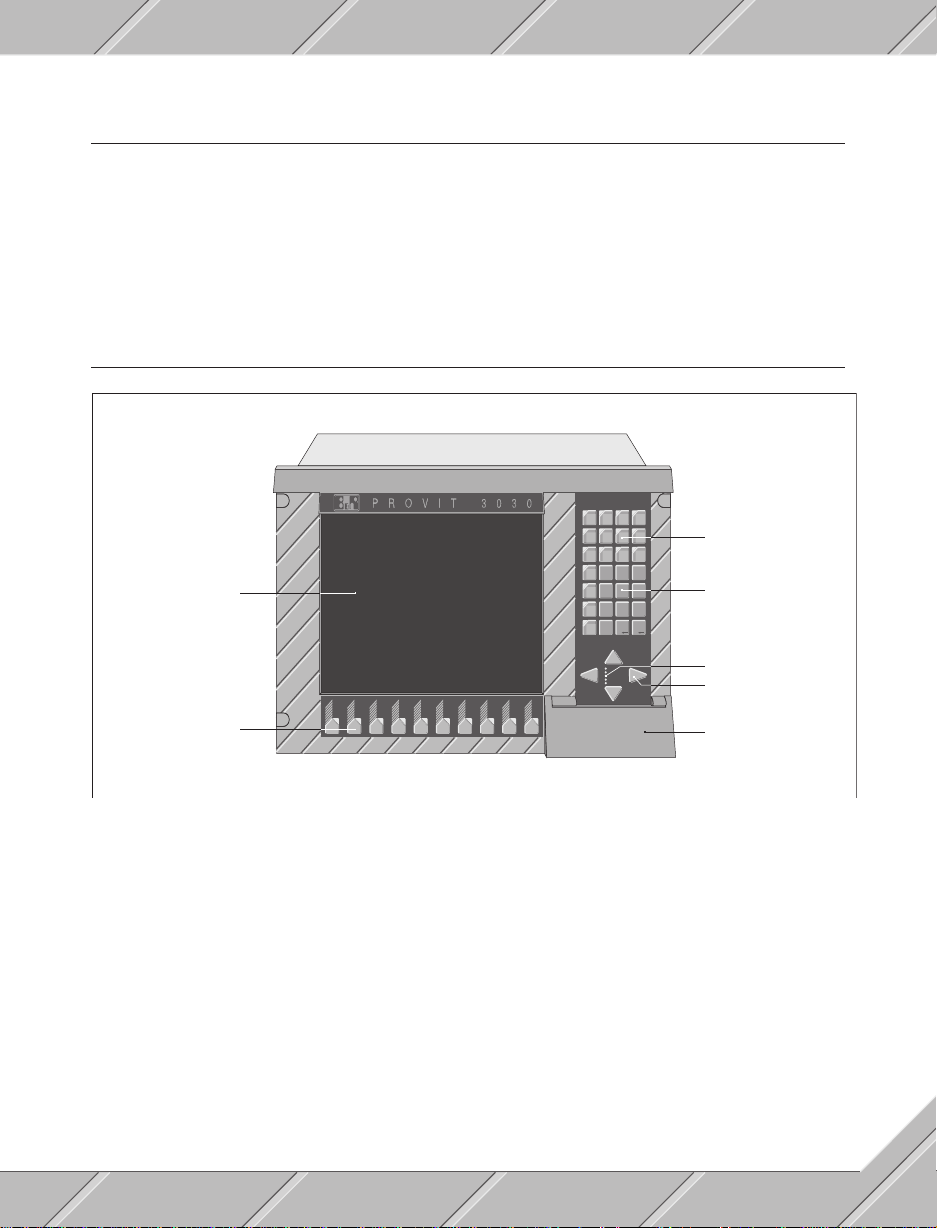
4.1 GENERAL
4.1.1 MEMORY
PROVIT 3030 models 286 and 386 SX both utilize a working memory of 2MB (dynamic RAM). The 386DX
and 486 models are standard with 4 MB. Memory can be expanded in 1 MB modules up to 16 MB in slots on
the CPU board (Section 6 "Options and Replacements" as well as the CPU User's manual contains more
information).
4.2 FRONT VIEW
User keys
7
8
Monitor safety glass
9
5
6
4
2
3
1
0
Number keys
Function keys
F1
F2 F3 F4 F5 F6 F7 F8 F9 F10
POWER
HDD
USER
WD
TEMP.
Status LEDs
Cursor keys
Flopy disk drive cover
33
Page 34
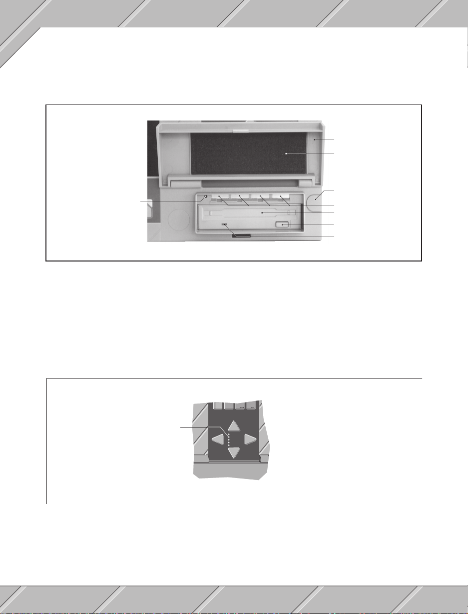
4.2.1 FLOPPY DISK DRIVE
The PROVIT 3030 industrial PC has a 3.5" floppy disk drive which is accessible from the front. The unit can
run double (720 KB) or high (1.44 MB) density diskettes.The drive is made dust and water proof with a sealed
door.
Floppy drive cover
Sealed
Screw cover
Reset key
Slots for key designation inserts
Diskette opening
Eject button
LED display
If the unit will be running in wet or dusty environments the door of the floppy drive must be closed and fastened
securely with a push until it locks into place.
4.2.2 HARD DISK DRIVE
The PROVIT 3030 industrial PC comes standard with a 52 MB hard disk drive. MS-DOS 5.0 is on the drive
in English for delivery. This can be changed to another version of MS-DOS by the user. Disk access is
displayed by means of a status LED.
0
LED display
POWER
HDD
USER
WD
TEMP.
34
Page 35
4.2.3 MONITOR
The 14" color monitor is controlled by a VGA card. The resolution and amount of colors depend on the
operating mode which is set for the VGA card (e.g. 1024 x 768 for 16 colors or 640 x 480 for 256 colors). The
safety glass used for the monitor is glare free, scratch resistant and improves readability.
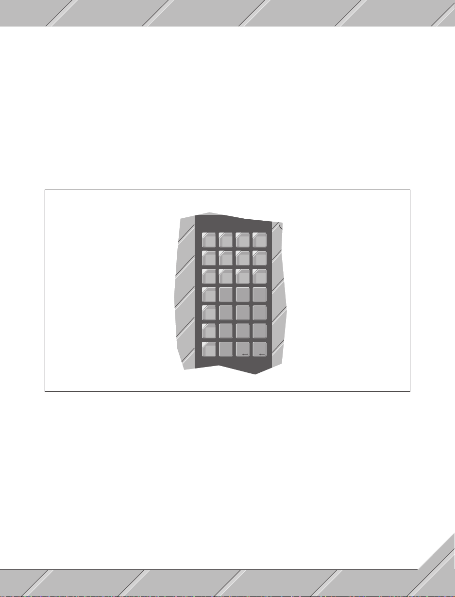
4.2.4 KEYBOARD
The built in matrix key pad works in parallel with a possible external keyboard connection. Key functions of
all function keys, cursor keys and number keys correspond directly with an AT keyboard. The lay out of the
user keys is as follows:
ALTWALTEALT
ALT
Q
ALT
ALTSALTDALT
A
ALTYALTXALTCALT
Esc
7
Ins
4
Del
1
-
0
R
F
V
9
8
6
5
3
2
35
Page 36
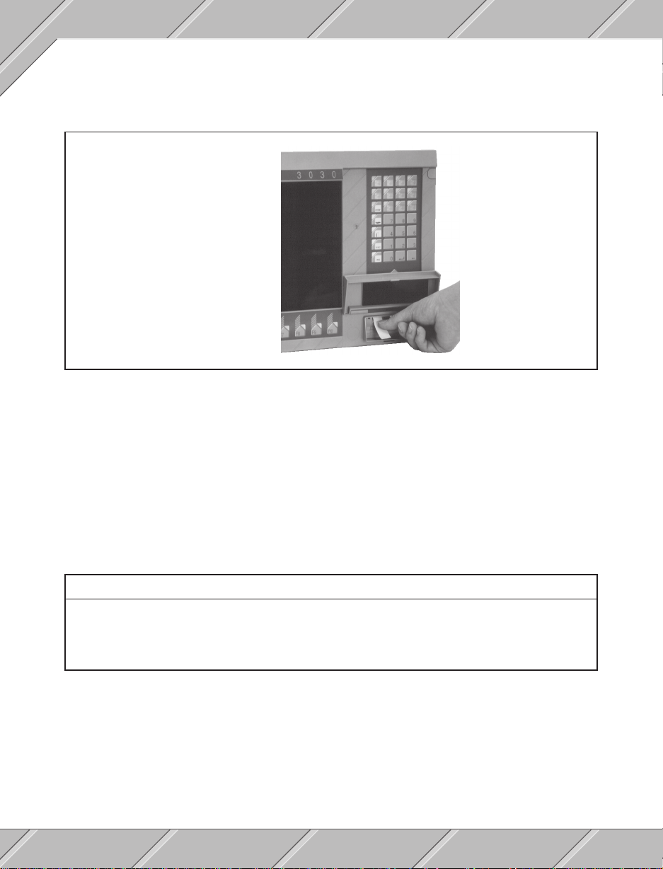
4.2.5 KEYBOARD LEGEND
Labelling the 16 function keys can be done with four plastic strips which are inserted behind the clear dust
and water proof key pad covering. The label strips are inserted from under the floppy drive flap.
There are five sheets of four insertable strips each delivered with the PROVIT 3030. These can be printed
on with a laser printer and cut out properly on the lines provided. The strips have punch outs for the key LEDs.
Insert strips can be ordered as replacements (Section 6 "Options and Replacements" contains more details).
4.2.6 KEY LEDs
Softkey and function keys are appointed with software controlled LEDs (Section 5 "Software" contains more
details). Individual keys can be illuminated for operator prompts or for status display.
4.2.7 STATUS LEDs
Five status LEDs are found centered among the cursor keys.
LEDLED
LED
LEDLED
POWER Power display. Lit always if the unit is in operation.
HDD Hard disk display. Lit when hard disk is accessed.
USER User LED. Can be switched on or off by the user (Section 5 "Software" contains more details).
WD Watchdog LED. Displays a CPU card failure.
TEMP Temperature watch. One of the two temperature measuring points has been measured as being too high.
FunctionFunction
Function
FunctionFunction
4.2.8 RESET BUTTON
The reset button is found under the floppy drive cover. The button can be accessed with a small pointed object
(e.g. a pen). By pressing the reset button a reset is executed with the memory test (cold start).
36
Page 37
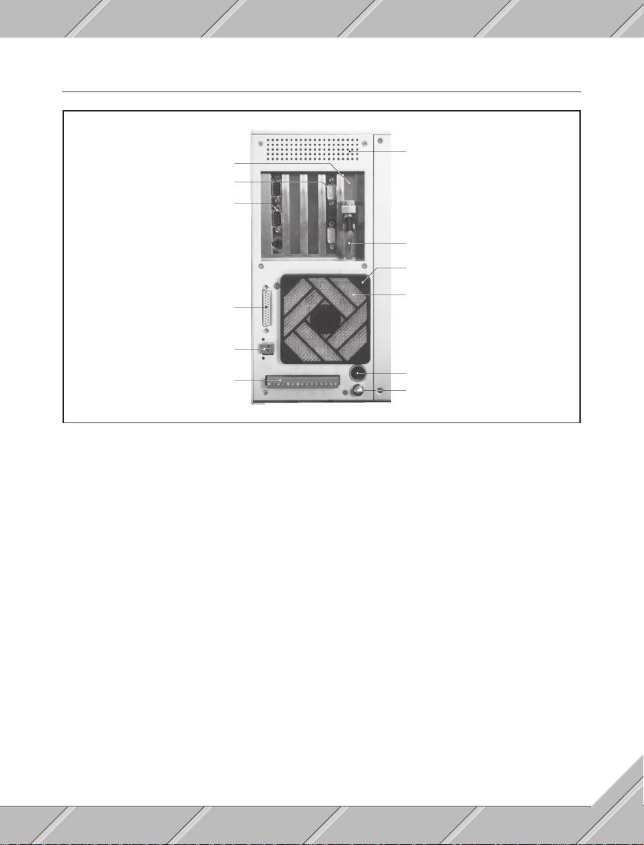
4.3 COMPUTER MODULE
Slot 5 with VGA card
Slot 4 with RS232 card
Slot 1 with CPU card
Parallel printer port
24 VDC output
I/O port
Air ventilation
VGA card - monitor connection
Fan cover
Fan grill
Keyboard interface
Hand screw
4.3.1 SLOTS
The PROVIT 3030 utilizes five slots for standard PC cards. The slots are numbered 1 - 5 from left to right.
The standard configuration upon delivery is:
- CPU card is in slot 1
- RS232 card is in slot 4
- VGA card is in slot 5
Slots 1 to 4 are built for long cards while slot 5 can only operate a short card. Long cards must be held in place
with the holders provided. Installation and removal of cards is explained in section 3 "Installation". If a slot is
free it must be covered.
4.3.2 MONITOR CONNECTION
The monitor cable reaches through the frame just under slot five of the computer module ( as displayed above).
The D-type connector must be always connected to the VGA card and held with screws.
37
Page 38
4.3.3 SERIAL INTERFACES
The PROVIT 3030 Industrial PC is provided with four serial RS232 interfaces. Two standard RS232 ports are
found on the CPU card in slot one. The RS232 card in slot four contains two electrically isolated serial
interfaces. Serial interfaces are set as follows upon delivery:
- CPU card COM1 and COM2 (COM1 top)
- RS232 card COM3 and COM4 (COM3 bottom)
These settings can be changed by jumpers (settings are detailed in the RS232 card users manual and the
CPU card users manual).
4.3.4 PARALLEL PRINTER INTERFACE
The parallel printer port (CENTRONICS) is situated on the rear of the computer module in the form of a 25
pin (F) D-type connector (see picture in section 4.3 "Computer module").
4.3.5 KEYBOARD INTERFACE
The keyboard interface (standard AT keyboard) is also situated on the rear of the computer module and is
in the form of an 8 pin DIN plug (F) (see picture in section 4.3 "Computer module").
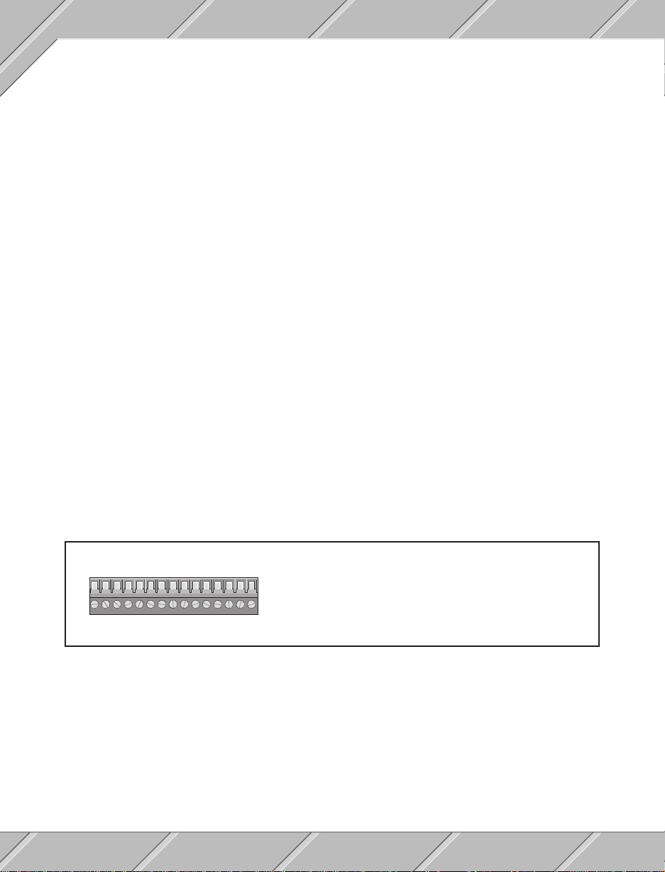
4.3.6 I/O PORT
The PROVIT 3030 Industrial PC utilizes five relay outputs and four digital inputs. Inputs and outputs are all
fed through a 15 way termination block situated on the rear of the computer module.
PinPin
123456789101112131415
FunctionFunction
Pin
Function
PinPin
FunctionFunction
1+2 Relay contact 1
3+4 Relay contact 2
5+6 Relay contact 3
7+8 Relay contact 4
9+10 Relay contact 5
PinPin
FunctionFunction
Pin
Function
PinPin
FunctionFunction
11 Input 1
12 Input 2
13 Input 3
14 Input 4
15 Input reference voltage
Control of outputs or inputs is described in section 5 "Software".
4.3.7 24 VDC OUTPUT
The 24 VDC output supplies the digital inputs. Maximum load is 500 mA.
38
Page 39
4.3.8 FAN
a
a
a
a
a
a
a
a
a
a
a
a
a
a
a
a
a
a
a
a
a
a
a
a
a
a
a
a
a
a
a
a
a
a
a
a
a
a
a
a
a
a
a
a
a
a
a
a
a
a
a
a
a
a
a
a
a
a
a
a
aaaaaaaaaaaaaaa
a
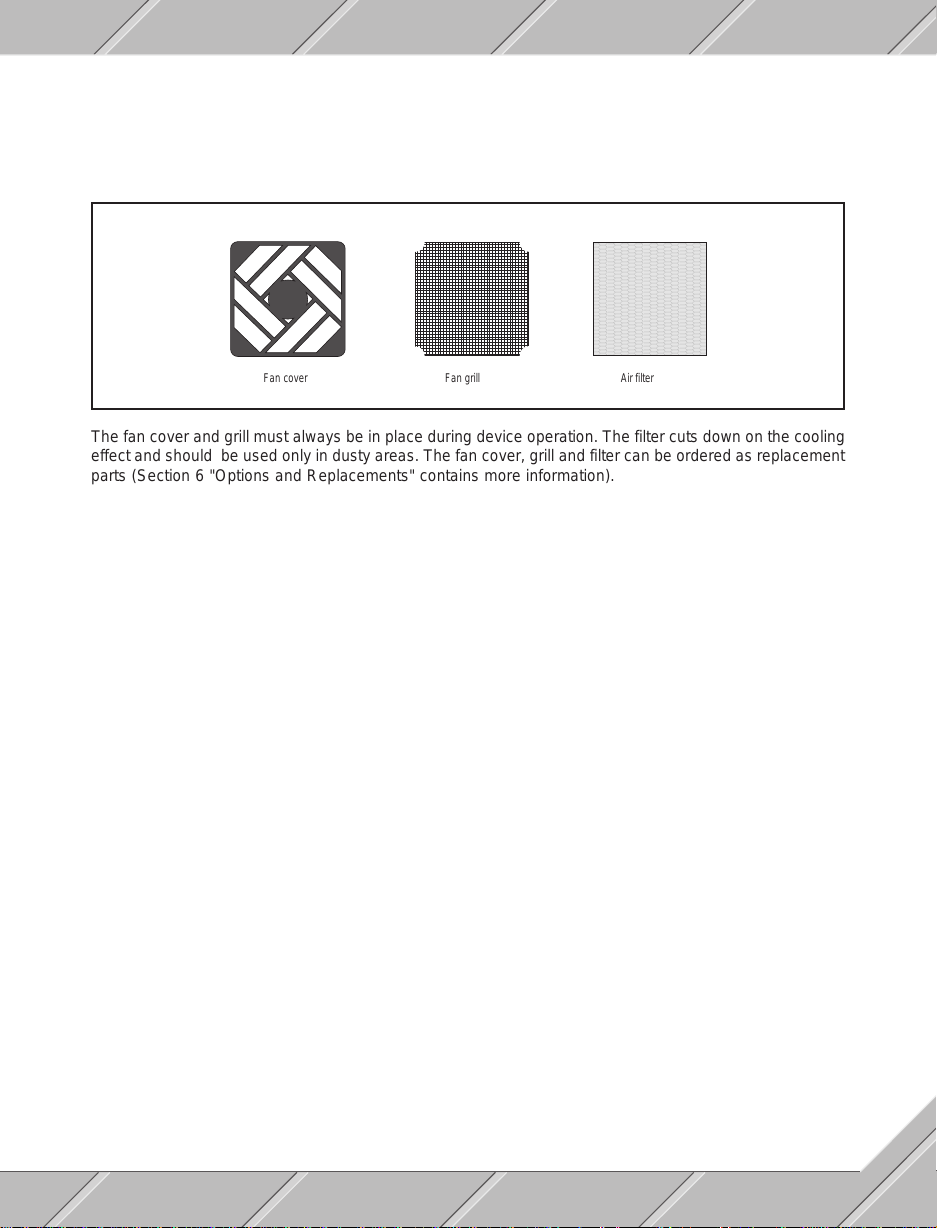
The fan provides a cool air flow. As long as the device is in operation the fan runs. The following fan
components are delivered with the PROVIT 3030:
a
a
aaaaaaaaaaa
aaaaaaaaaaa
aaa
a
a
aaaaaaaaaaa
aaaaaaaaaaaaa
aaaaaaaaaaaaa
a
a
aaaaaaaaaaa
aaaaaaaaaaa
aaa
a
a
aaaaaaaaaaa
aaaaaaaaaaaaa
aaaaaaaaaaaaa
a
a
aaaaaaaaaaa
aaaaaaaaaaa
aaa
a
a
aaaaaaaaaaa
aaaaaaaaaaaaa
aaaaaaaaaaaaa
a
a
aaaaaaaaaaa
aaaaaaaaaaa
aaa
a
a
aaaaaaaaaaa
a
a
aaaaaaaaaaa
aaaaaaaaaaaaa
aaaaaaaaaaaaa
aaaaaaaaaaa
aaa
a
a
aaaaaaaaaaa
a
a
aaaaaaaaaaa
aaaaaaaaaaaaa
aaaaaaaaaaaaa
aaaaaaaaaaa
aaa
a
a
aaaaaaaaaaa
a
a
aaaaaaaaaaa
aaaaaaaaaaaaa
a
a
a
a
a
a
a
a
a
a
a
a
a
a
a
a
a
a
a
a
a
a
a
a
Fan cover Fan grill Air filter
The fan cover and grill must always be in place during device operation. The filter cuts down on the cooling
effect and should be used only in dusty areas. The fan cover, grill and filter can be ordered as replacement
parts (Section 6 "Options and Replacements" contains more information).
39
Page 40
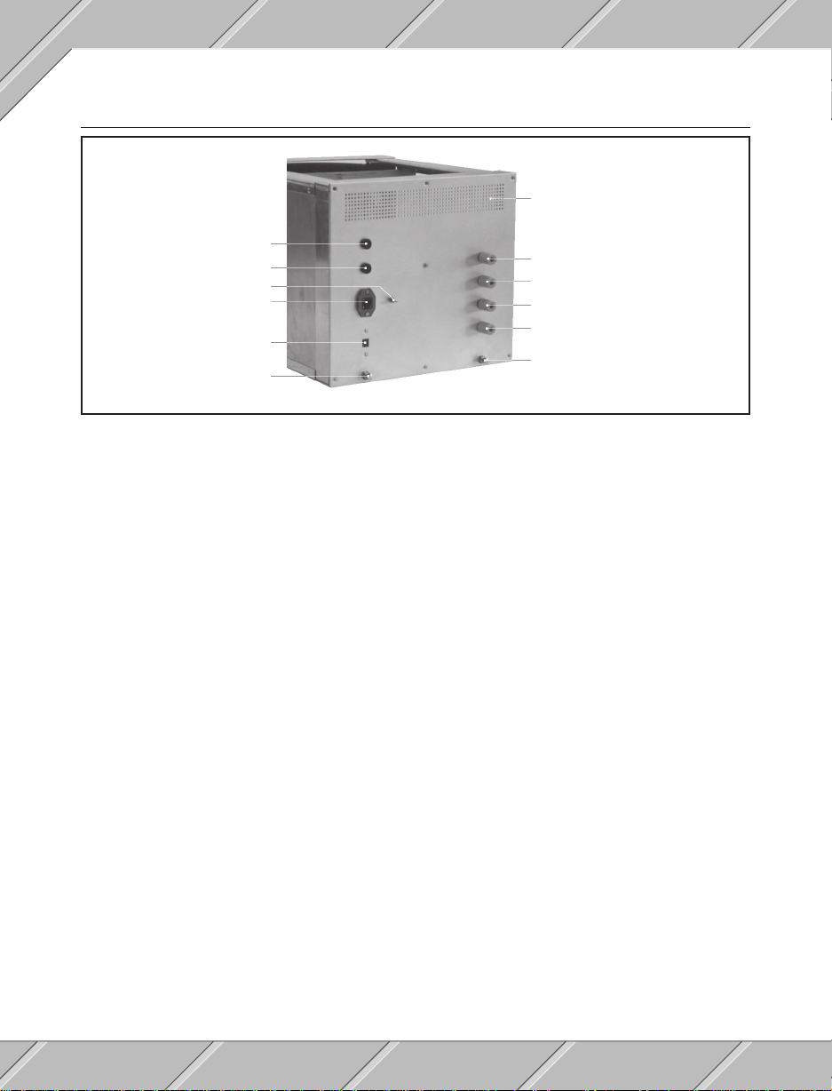
4.4 MONITOR MODULE
Air ventilation
Monitor fuse
CPU fuse
Ground connection
Power
Voltage selector switch
Hand screw
Vertical position
Horizontal position
Brightness
Contrast
Hand screw
4.4.1 FUSES
Monitor and CPU fuses are installed for the PROVIT 3030 delivery.
- Monitor fuse 2 A / 250 V
- CPU fuse 5 A / 250 V
Only fuses with the same specification may be used as replacements.
4.4.2 VOLTAGE SELECTION SWITCH
The PROVIT 3030 industrial PC can be switched from 220 VAC to 120 VAC for use in different areas. The
switch is set to 220 VAC as a standard for delivery. Before starting up be sure to check for the proper voltage
selection depending on the area of the world that you are in.
4.4.3 POWER CONNECTION
A power cable is included with the delivery. On the device end the proper connector with screws for fastening
is attached. The other end is left up to the user whereas it can be terminated with a conventional plug or can
be wired in directly.
Attention:
- Only mains plugs with a proper ground termination may be used.
- Terminations may only be wired by authorized, qualified personnel.
- Know the regulations regarding electronic installations in your area.
40
Page 41

4.4.4 MONITOR SETTINGS
Horizontal and vertical positions as well as brightness and contrast can be set with four potentiometers on
the rear side of the monitor module (see picture in section 4.4). When the settings are complete the adjustment
knobs can be removed to prevent unwanted adjusting.
4.4.5 GROUND CONNECTION
An additional ground connection can be made on the rear of the monitor module with the ground termination
screw (see picture in section 4.4).
41
Page 42

42
Page 43

SECTION 5
SOFTWARE
43
Page 44

44
Page 45
5.1 B&R UTILITY DISKETTE
The B&R utility diskette (model. No. 1C0110.01-310) is included in the scope of delivery with the PROVIT
3030. The B&R utility diskette also includes a test program (PROV3030.EXE), with which the following
PROVIT 3030 industrial PC functions can be tested:
- Key code assignments
- Key LED controls
- Relay output set and reset
- Digital input requests
- Monitor color display
- Hard disk test (chkdsk)
- Floppy drive test (chkdsk)
The test program can be run in English, French, German, Italian or Spanish. Language selection is done at
the beginning of the program by pressing a function key. The relay output set / reset can be set with the test
program. Be careful of the effect that setting the relay output could have on the device currently connected.
5.2 I/O PORTS
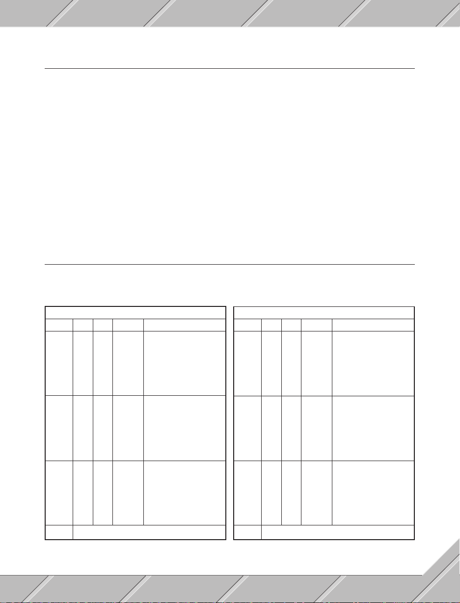
The PROVIT 3030 industrial PC has two I/O ports which are addressed by addresses $300 to $307.
I/O PORT 1
AddressAddress
PortPort
BitBit
Address
Port
AddressAddress
PortPort
$300 A 0 out LED 0
$301 B 0 out LED 8
$302 C 0 in Input 1
$303 MODE ($89)
DirectionDirection
Bit
Direction
BitBit
DirectionDirection
1 out LED 1
2 out LED 2
3 out LED 3
4 out LED 4
5 out LED 5
6 out LED 6
7 out LED 7
1 out LED 9
2 out LED 10
3 out LED 11
4 out LED 12
5 out LED 13
6 out LED 14
7 out LED 15
1 in Input 2
2 in Input 3
3 in Input 4
4 in Reserved
5 in Reserved
6 in Temperature watch 1
7 in Temperature watch 2
FunctionFunction
Function
FunctionFunction
AddressAddress
PortPort
Address
Port
AddressAddress
PortPort
$304 A 0 out LED F1
$305 B 0 out LED F9
$306 C 0 out Boot Force
$307 MODE ($80)
I/O PORT 2
BitBit
DirectionDirection
Bit
Direction
BitBit
DirectionDirection
1 out LED F2
2 out LED F3
3 out LED F4
4 out LED F5
5 out LED F6
6 out LED F7
7 out LED F8
1 out LED F10
2 out Reserved
3 out Reserved
4 out Reserved
5 out Reserved
6 out Reserved
7 out Reserved
1 out Output 1
2 out Output 2
3 out Output 3
4 out Output 4
5 out Output 5
6 out Reserved
7 out User LED
FunctionFunction
Function
FunctionFunction
I/O port mode registers ($303 for I/O port 1; $307 for I/O port 2) must be written with the corresponding
preset value with every reset (Initialization).
45
Page 46
5.2.1 KEY LEDs
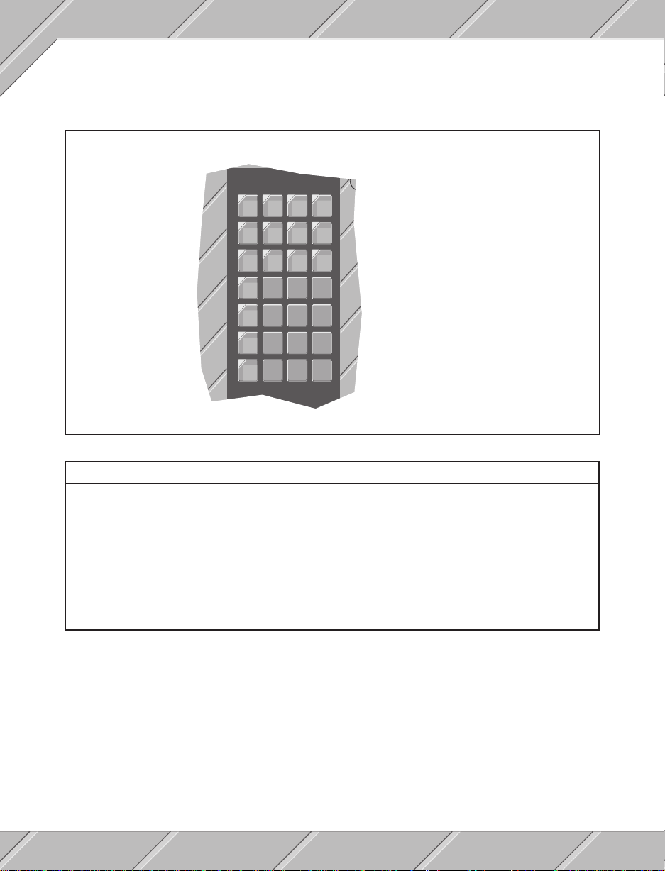
Both I/O ports are utilized for key LED control. User key LEDs are controlled through port one.
Key
123
0
4
567
891011
12
13
14
15
Address
0
1
2
3
4
5
6
7
8
9
10
11
12
13
14
15
$300
$300
$300
$300
$300
$300
$300
$300
$301
$301
$301
$301
$301
$301
$301
$301
Bit
0
1
2
3
4
5
6
7
0
1
2
3
4
5
6
7
Function keys are controlled through I/O port two:
KeyKey
Key
KeyKey
F1 $304 0
F2 $304 1
F3 $304 2
F4 $304 3
F5 $304 4
F6 $304 5
F7 $304 6
F8 $304 7
F9 $305 0
F10 $305 1
46
AddressAddress
Address
AddressAddress
BitBit
Bit
BitBit
Page 47
5.2.2 USER LED
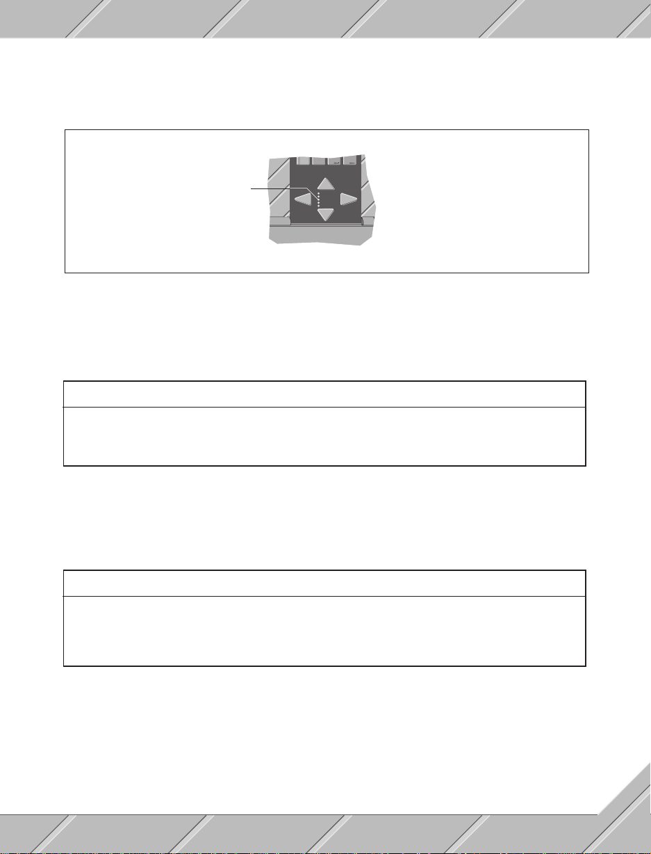
The user LED is controlled through I/O port two (address $306, Bit 7).
0
User-LED
POWER
HDD
USER
WD
TEMP.
5.2.3 DIGITAL INPUTS
The status of all four digital inputs can be read from the following addresses.
InputInput
Input
InputInput
1 $302 0
2 $302 1
3 $302 2
4 $302 3
AddressAddress
Address
AddressAddress
BitBit
Bit
BitBit
5.2.4 RELAY OUTPUTS
All five relay outputs can be set / reset with the following addresses.
OutputOutput
Output
OutputOutput
1 $306 1
2 $306 2
3 $306 3
4 $306 4
5 $306 5
AddressAddress
Address
AddressAddress
BitBit
Bit
BitBit
47
Page 48

5.2.5 TEMPERATURE MONITORING
The flow of cool air from the fan follows a predefined course through the device:
- Fan
- Hard disk
- Floppy disk drive
- Boards
- Air vents
The temperature inside of the device is monitored by two sensors. Sensor number one keeps track of the cool
air before it gets to the boards and sensor number two watches the temperature of the air on its way out through
the vents. The status of the temperature monitor can be read from the following addresses.
SensorSensor
Sensor
SensorSensor
1 $302 6
2 $302 7
AddressAddress
Address
AddressAddress
BitBit
Bit
BitBit
If one of the temperature monitors is addressed (set to 1), immediate measures must be taken to reduce the
temperature inside the device (additional external cooling unit or switch the device off).
48
Page 49

5.3 ADDRESSES AND INTERRUPTS
5.3.1 ADDRESSES
PROVIT 3030 industrial PC addresses correspond with an AT personal computer, with the exception of I/O
ports. The I/O ports used addresses $300 to $307. Addresses $308 to $31F are used for looking at prospective
function expansion and should not be used by the user.
5.3.2 INTERRUPTS
The following interrupts are set on the PROVIT 3030 before delivery:
IRQ 0 System Timer
IRQ 1 Keyboard
IRQ 2 [Cascade]
IRQ 3 COM2
IRQ 4 COM1
IRQ 5 Free (e.g. for B&R on-line interface module)
IRQ 6 Floppy disk drive
IRQ 7 LPT1
IRQ 8 Time / date
IRQ 9 VG A
IRQ 10 COM4
IRQ 11 COM3
IRQ 12 Free
IRQ 13 Reserved for APU
IRQ 14 Hard disk drive
IRQ 15 Free
49
Page 50

50
Page 51

SECTION 6
OPTIONS AND REPLACEMENTS
51
Page 52

52
Page 53
6.1 KEYBOARD CASE
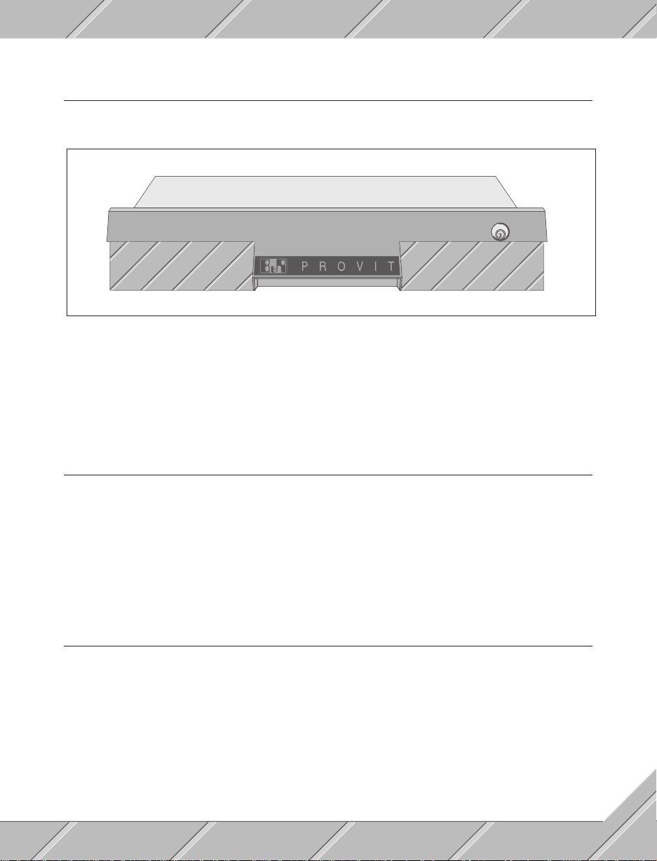
A standard AT keyboard can be connected to the keyboard interface on the PROVIT 3030. B&R offers an
optional AT keyboard in a protective industrial case.
The keyboard case is built for installation in a 19" cabinet or it can be mounted in a wall mount situation. The
keyboard pulls out of the frame on rails with angle adjustment to allow for easier keyboard access. The case
is water and dust proof to IP54 standards.
Model number: 5H0000.00-010 (Documentation in German)
5H0000.00-020 (Documentation in English)
6.2 RS232 INTERFACE CARD
Included in the scope of delivery with the PROVIT 3030 industrial PC is an RS232 card. Two electrically
isolated RS232 ports are built into the card. Jumpers can be set to switch between interface designation or
interrupt numbers (COM 1, COM 2, ...).
Model number: 5A1102.00-090
6.3 CPU CARDS
The following CPU cards are available for the PROVIT 3030:
- 286 / 16 MHz (Model. No. 5A0001.00-020)
- 386 SX / 25 MHz (Model. No. 5A0002.00-020)
- 386 DX / 33 MHz (Model. No. 5A0003.00-020)
- 486 / 33 MHz (available from july 1992)
If the CPU card is ordered individually (e.g. to upgrade a 386 SX to a 386 DX), no memory is attached. The
memory must be ordered separately (Section 6.5 "Memory expansion" contains more details).
53
Page 54

6.4 VGA CARD
The VGA card controls the monitor output. Several operating modes can be set with the software provided.
The resolution is maximum 1024 x 768.
Model number: 5A1103.00-020
6.5 MEMORY EXPANSION
The 286 and 386 SX models are delivered with 2 MB RAM and the 386 DX and 486 have 4 MB. 1 MB expansion
modules are available for the PROVIT 3030. Memory expansion is done as follows:
- for 286 and 386 SX in 2 Mb steps
- for 386 DX and 486 in 4 MB steps
Memory expansion modules are inserted in slots on the CPU card (the CPU card user's manual contains more
details).
Model number: 5A1001.00-010
6.6 INTERFACE MODULE FOR PLC PROGRAMMING
To program MINICONTROL, M264, MIDICONTROL, or MULTICONTROL PLC systems with the B&R
PROVIT 3030 an on-line interface module is required to communicate with the PLC processor (Model No.
BRIFPC-0). The on-line interface module has two TTY interfaces for programming two PLC processor
modules simultaneously.
6.7 CENTRONICS / ON-LINE CONVERTER
For programming MINICONTROL, M264, MIDICONTROL or MULTICONTROL PLC systems a CENTRONICS
on-line convertor (Model No. BRKAOL5-1) can be used as an alternative. The CENTRONICS on-line
convertor is connected to the parallel printer interface of the PROVIT 3030. This facilitates PLC processor
programming.
54
Page 55
6.8 REPLACEMENT PARTS
ItemItem
Item
ItemItem
B&R utility diskette 1C0110.01-310
Utilities 4 screws M6, 4 nuts M6, 4 washers M6, 4 contact washers M6, 5A0000.00-011
Key designation strips 10 strips 5A0000.00-012
Power cable 5A0000.00-013
Termination blocks 15 pole termination block for I/O port 5A0000.00-014
Consisting ofConsisting of
Consisting of
Consisting ofConsisting of
4 cage nuts M6, 4 screw covers, fan cover, fan grill, air filter
5 card holders, 4 potentiometer adjustment knobs, housing gasket
2 pole termination block for 24 VDC output
Model No.Model No.
Model No.
Model No.Model No.
55
Page 56

56
Page 57

B&R SALES AND
SERVICE
57
Page 58

AUSTRIA
B&R Headquarters (1979)
Development, Production,
Sales, Applications, Training
Bernecker + Rainer
Industrie-Elektronik Ges.m.b.H.
A-5142 Eggelsberg 120
Tel: 07748 / 6586-0
Ttx: 027477
Fax: 07748 / 6585-26
AUSTRALIA
B&R Representative
Sales, Applications, Training
PROCON INSTRUMENT TECHNOLOGY PTY. LTD.
30 Thomas St, West End. Q. 4101
Woolloongabba, Qld. 4102
Tel: +61 / (07) 846 3511
Fax: +61 / (07) 846 1588
TECHNICAL OFFICES IN GERMANY
Sales, Applications, Training
TB Bayern TB Südwest
Freisinger Str. 34 Friedrich-Dürr-Str. 70
D-8045 Ismaning D-7100 Heilbronn
Tel: 089 / 996554-0 Tel: 07131 / 5971-0
Fax: 089 / 996554-99 Fax: 07131 / 5971-71
TB West TB Mitte
Bahnhofstr. 24 Ernst-Wiss-Str. 18
D-4250 Bottrop D-6000 Frankfurt 80
Tel: 02041 / 25172 Tel: 069 / 380315-0
Fax: 02041 / 688767 Fax: 069 / 380315-73
TB Südost TB Nordost
Georg-Schwarz-Str. 4 Gemeinschaftsstr. 16
O-7033 Leipzig O-1199 Berlin
Tel: 0037 / 41-475894 Tel: 0037 / 2-6770363
Fax: 0037 / 41-475818
TB Nord
Ernst-Grote-Str. 2-4
D-3004 Isernhagen 1
Tel: 0511 / 614077
Fax: 0511 / 612337
BENELUX
B&R Subsiduary (1989)
Sales, Applications, Training
B&R Industrièle Automatisering B.V.
Takkebijsters 9c
4817 BL Breda
Tel: 076 / 715303
Fax: 076 / 715306
CYPRUS
B&R Representative
Sales, Application, Training
TONIS G. PAVLIDES
Electrical & Mechanical Contractor
75 c, Makarios III Ave.,
Limassol, Cyprus
Tel: +51 / 37906 - (051) 37246
Fax: +51 / 39322
DENMARK
B&R Representative
Sales, Applications, Training
HANO Elektroteknik A/S
Klokkestobervej 15
5230 Odense M
Tel: +459 / 65930400
Fax: +459 / 65930700
GERMANY
B&R Subsiduary (1983)
Sales, Applications, Training
B&R Industrie-Elektronik GMBH
Ernst-Wiss-Straße 18
D-6000 Frankfurt 80
Tel: 069 / 380315-0
Ttx: 841 / 176990824
Fax: 069 / 39701
FINLAND
B&R Representative
Sales, Applications, Training
DELCON OY
Läkkisepanthie 11
SF-00620 Helsinki
Tel: +00358 / 0-7571744
Tx: +857 / 1233989
Fax: +00358 / 0-7571802
FRANCE
B&R Representative
Sales, Applications, Training
ABR automation
5, rue du Vallon
94440 Marolles en Brie
Tel: +(1) 45692332
Fax: +(1) 45990864
GREAT BRITAIN
B&R Subsiduary (1988)
Sales, Applications, Training
B&R Industrial Automation Ltd.
Milnyard Square, Orton Southgate
Peterborough, PE2 OGX
Tel: 0733 / 371320
Fax: 0733 / 371306
HUNGARY
B&R Representative
Sales, Application, Training
DIALOG GmbH
Thököly üt 7.
H-1076 Budapest
Tel: +36 / 11423302
Fax: +36 / 11423768
58
Page 59

INDIA
B&R Representative
Sales, Applications, Training
Address, telephone and fax numbers
on request
SINGAPORE
B&R Representative
Sales, Applications, Training
SUMBER CO. PTE. LTD
1 & 3, Jalan Kilang Barat
Singapore 0315
Tel: 65 / 2716086
Fax: 65 / 2784521
ITALY
B&R Subsiduary (1987)
Sales, Applications, Training
B&R Automazione Industriale S.p.A.
Viale Certosa 191
I-20151 Milano
Tel: 02 / 3085844, 3083822, 3084358
Fax: 02 / 38001864
MEXICO
B&R Representative
Sales, Applications, Training
SCAN, S.A. DE C.V.
Paseo de los Leones163
Col. Mitras Centro
Monterrey, N.L. 64460
Tel: +83 / 487122, 485379
NORWAY
B&R Representative
Sales, Applications, Training
Kverneland Elektriske A/S
Oksnevad Ring 14
N-4062 Klepp St
Tel: +4 / 423840
Fax: +4 / 423840
POLAND
B&R Representative
Sales, Applications, Training
CONSTEL Sp.zo.o.
43-450 USTRON
ul. Swierczewskiego 17
Tel: +23 / 66
Tx: +038488 const pl
SLOWENIA
B&R Representative
Sales, Applications, Training
Address, Telephone numbers
and Fax numbers on request
SOUTH AFRICA
B&R Representative
Sales, Applications, Training
PROLOCON
Ground Floor Helvetia House
Greenvale Road, Wilbart, Germiston
P.O. Box 130658, 2021 Bryanston
Tel: +011 / 45557101
Fax: +011 / 4555842
SPAIN
B&R Representative
Sales, Applications, Training
LARRAIOZ
Larraioz Etxea (Apartado 193)
20800 Zarautz (Gipuzkoa)
Tel: +(9.43) 13.21.39*
Fax: +(9.43) 13.13.27
SWITZERLAND
B&R Subsiduary (1987)
Sales, Applications, Training
B&R Industrie Automation AG
Langfeldstr. 88
CH-8500 Frauenfeld
Tel: 054 / 217425
Tx: bur ch 897767
Fax: 054 / 217424
RUSSIA
B&R Representative
Sales, Applications, Training
TJUNEX AG
Profsojuznaja 65/681
117806 Moskau
Tel: +095 / 334-90-31
Fax: +095 / 420-20-16
TAIWAN
B&R Representative
Sales, Applications, Training
Dr. Tsai Computer & Automation Co., Ltd.
No. 193 Kung Ming Street,
Taipei, Taiwan
Tel: +2 / 3110195
Fax: +2 / 3111266
59
Page 60

UKRAINE
B&R Representative
Sales, Applications, Training
SKIF ENGINEERING
50 Zhovtea avenue, 106
274018 Tchernovtzy
Tel: 3-90-69, 4-89-97
Fax: 03722 / 48994
USA
B&R Subsiduary (1987)
Sales, Application, Training
B&R Industrial Automation Corp.
1325 Northmeadow Parkway Suite 130
Roswell, Georgia 30076
Tel: 404 772-0400
Fax: 404 772-0243
YUGOSLAVIA
B&R Representative
Sales, Applications, Training
Addresses, telephone numbers
and fax numbers on request
60
Page 61

INDEX
61
Page 62

Symbol
24 VDC output 38
A
Access time 11
Addresses 49
Air circulation 29
Air flow 29
AT-keyboard 53
C
Cache 11
Card installation 23
Card safety holders 55
CENTRONICS/online converter 54
Checking the delivery 15
Color monitor 11, 35
Computer module 21, 22, 37
Contents of delivery 15
Cooling 39, 48
CPU card 37, 38
CPU card 53
CPU fuse 40
Cursor keys 35
D
Depth 11
Device description 31
Dimensions 11
Documentation 10
Dust 39
Dust / air filter 18, 39, 55
F
Fan 18, 39, 48
Fan cover 18, 39, 55
Fan grill 18, 39, 55
Fan set 55
Flexibility 9
Floppy disk drive 11, 34, 45, 48
Floppy drive cover 34, 36
Functionality 9
Funktion keys 35, 36, 46
Fuses 40
G
Ground connection 41
Ground screw 41
Ground termination 41
H
Hand screws 17, 21
Hard disk 11, 34, 45, 48
Height 11
Housing 21, 26
Housing gasket 26, 55
Humidity 11
I
I/O port 38
I/O ports 45
Industrial quality 9
Input voltage 11
Inputs 11, 45, 47
Install procedures 13
Installation 19
Installation in a 19" rack 27
Installation in a wall 28
Interfaces 11
Interrupts 49
K
Key codes 45
Key designation 34, 36, 55
Key LEDs 36, 45, 46
Keyboard 11, 35, 53
Keyboard case 53
Keyboard interface 38, 53
Keyboard labeling 36
L
LEDs 46
M
Matrix keyboard 35
62
Page 63

Memory 11, 33, 54
Memory expansion 54
Memory expansion modules 54
Memory modules 33
Mode register 45
Model numbers 11
Monitor 11, 35, 37, 41, 54
Monitor colors 45
Monitor connection 37
Monitor fuse 40
Monitor module 21, 24, 25, 40
Monitor safety glass 35
Monitor settings 41
Mounting 11
Mounting set 55
MS-DOS 10, 34
N
Number keys 35
O
Online interface module 54
Operating system 11
Operating temperature 11
Options 11, 51
Outputs 11, 38
RS232 card 37, 38, 53
RS232 interfaces 38, 53
S
Sales and service 57
Screw covers 29
Serial interfaces 38
Slots 11, 37
Softkey LEDs 46
Softkeys 35, 36
Software 43
T
Technical data 11
Temperature sensors 48
Temperature watch 45, 48
Termination block 18, 55
Termination block set 55
Test programm 45
Transport accidents 15
Transport security screws 17
U
Unpacking 15
User LED 47
Utilities 55
Utility diskette 45, 55
P
Packaging 15
PLC programming 54
Potentiometer 41
Potentiometer adjustment knobs 18, 41, 55
Power 16
Power cable 16, 40, 55
Power connection 40
Power connectors 16, 40
Power supply 11
Printer port 37, 38
Processor 11
Protection 11
R
Relay contact 11, 38
Relay output 45, 47
Replacements 51, 55
Reset 48
V
VGA card 37, 54
Voltage selection switch 16, 40
Voltage Selector 16
W
Weight 11
Width 11
Working memory 33
63
Page 64

64
 Loading...