

Page 1

Page 1 of 11
s
u
4
8
h
EMC Technologie
ABN 82 057 105 549
Unit 3/87 Station Road
Seven Hills NSW 2147 A
Telephone +61 2 962
Facsimile +61 2 983
Email syd@emctec
www.emctech.com.au
APPENDIX L
OF
TEST REPORT T60821_F
USER MANUALS FOR THE BQT AND PAC
FCC ID:
Manufacturer:
Test Sample:
Model:
Serial Number:
Date:
QVL-MIP9
BQT Solutions (Australia) Pty Ltd
Contactless Smart Card Reader
MiP9 and 900-PAC
None
29th August 2006
Melbourne
57 Assembly Drive
Tullamarine Vic 3043
Tel: +61 3 9335 3333
Fax: +61 3 9338 9260
Sydney
Unit 3/87 Station Road
Seven Hills NSW 2147
Tel: +61 2 9624 2777
Fax: +61 2 9838 4050
Brisbane
1/15 Success St reet
Acacia Ridge Qld 4110
Tel: +61 7 3875 2455
Fax: +61 7 3875 2466
Auckland (NZ)
47 MacKelvie Street
Grey Lynn Auckland
Tel: +64 9 360 0862
Fax: +64 9 360 0861
Page 2
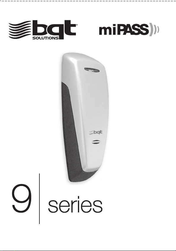
INSTALLATION GUIDE
Version 2.8
9 series_v2.8 Aug06
Page 3

Introduction
Thank you for purchasing a miPASS 9 Series Mifare Contactless Smart Card Reader. Available in 4 different
models catering for all security requirements large or small, whether your projects are price or functionality
driven. The 9 Series reader models are:
DF900 - DESFire
BT900- Mifare (standard)
miP9 - BQT SPEK
CSN9 - Card Serial Number
The 9 Series reader is used in security applications and interfaces into Wiegand applications.
The 9 Series reader is preset with specific 'Keys'. Valid smart cards are issued with the same 'Keys'. This
ensures that the system cannot be compromised. (No 'Keys" used for CSN9 model)
The reader incorporates a LED and Buzzer to provide feedback to a person wishing to enter. The control of
these is shared by the reader and security controller.
The 9 Series reader is low-profile and can be installed in new installations or as an upgraded reader in existing
proximity access control systems.
Installation
Remove the cover by holding the unit as
shown and pulling the cover from the top as illustrated
Page 4
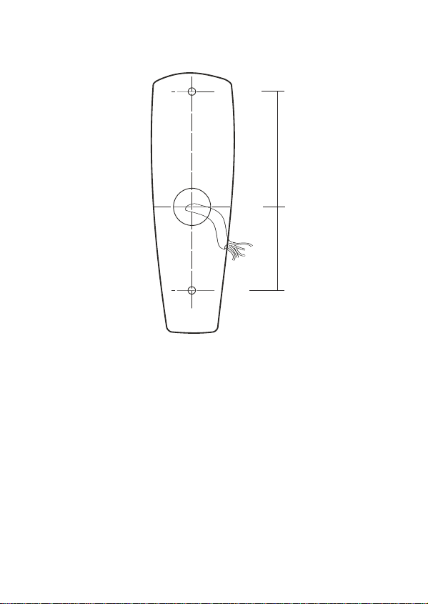
If necessary, drill holes for the mounting screws in the wall or mounting box on which the reader unit will be
placed. (Use the Drilling Template provided).
4mm Ø
20mm Ø
4mm Ø
➣➣
62mm
45mm
➣➣
WALL VIEW
(not to scale)
1. Place the controller and power supply cable through the Grommit hole.
2. Drill the holes as indicated by the arrows.
Note: Make sure that you don't drill through the cable.
Check your circuit diagram for the colour coding of the circuit wiring. The reader can be damaged beyond
repair if the wiring is connected incorrectly.
Page 5

If the reader has the same power supply as the door latch relay, make sure that the relay is
protected by a fast Schottky diode. If the relay is not protected reader operation will be affected.
NOTE: Power to the unit is provided from the Listed control unit or from a separately supplied UL Listed
12 Vdc power-limited, access control power source.
Wiring methods shall be in accordance with the National Electrical Code, ANSI/NFPA 70.
1. Connect the 0V wire to the Power 0V line.
NOTE: The 0V line of all power supplies MUST be connected to a common 0V reference point.
2. Connect the Wiegand signal cables.
3. Connect the Buzzer and the LED cables.
4. Attach the 12Vdc wire last.
5. Place the reader on the wall (Make sure the wires are not crushed)
6. Insert and hand tighten the screws.
7. Check that the reader is level before tightening the screws.
NOTE: Excessive tightening of screws may deform the casing, resulting in a damaged unit.
This will void the warranty.
8. Replace the cover.
9. Power up the reader.
NOTE: The unit needs up to 15 seconds to set up before it can respond to a valid smart card.
Page 6

External Use
Mount the reader on a suitable external single gang surface mount box.
USA ONLY - BQT mounting plate adaptor is available for mounting to a US single gang box.
Make sure that the wire bundle to the 9 Series reader has an IP rating of at least IP67.
Use warming pads if the temperature of the reader is expected to fall below -10ºC (14ºF).
Handling
Handle the 9 Series reader with care. Do not damage/drop unit before installation.
The reader unit will not be waterproof if the casing is damaged. Replace the reader if the casing is
damaged.
Maintenance
Once installed the 9 Series reader requires no maintenance.
Troubleshooting
If the reader doesn't respond when a valid smart card is presented, check the following.
Symptom
LED is not lit
LED is Orange or Buzzer sounds low
Reader doesn't respond
Reader beeps but lock doesn't open
Possible Cause
No power to the reader
Voltage to the reader is below 10V
Invalid card or card is faulty
Wiring to the controller may be faulty.
NOTE: If reader beeps when a valid smart card is presented
then the reader is functioning.
Check
Check the power supply to the reader.
Check the power supply to the reader
Check reader with another valid smart card
Check the wiring to the controller
If the problem still persists then please contact your distributor for technical support and to obtain an RMA if
required.
Warranty
The 9 Series reader comes with a 5 year warranty from the date of dispatch from BQT Solutions. The
warranty is void if the instructions contained within this manual have not been adhered to.
Page 7
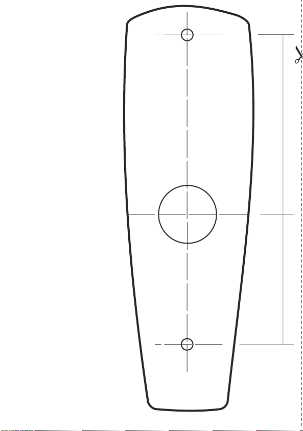
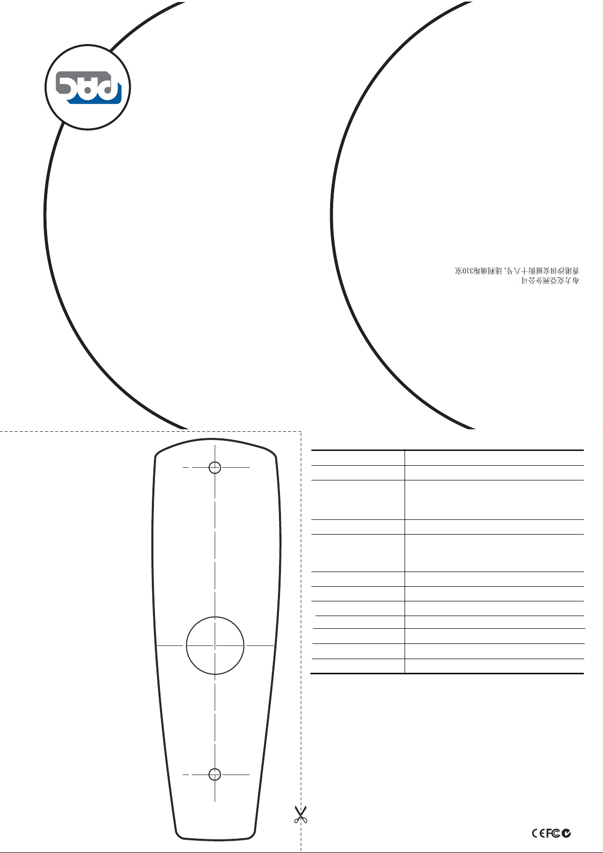
Drilling Template
For all 9 Series readers
●
20mm (0.79”) diameter
hole for wire entry
●
2 x 4 mm (0.16”) diameter
holes for mounting screws
●
Minimum reader dimensions
are 140mm x 45 mm
(5.51" x 1.77")
4mm Ø
20mm Ø
4mm Ø
➣➣
62mm
45mm
➣➣
Copyright © 2006 BQT Solutions Limited. BQT Solutions and the BQT Solutions
logo are registered trademarks of BQT Solutions (Australia) Pty Ltd.
Mifare is a registered trademark of Philips Electronics.
Page 8
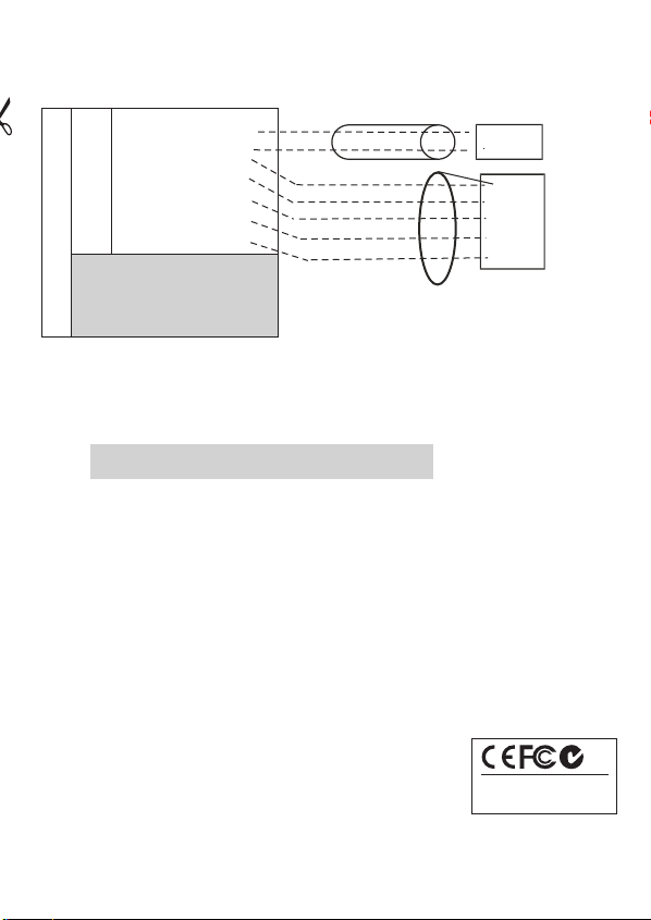
Wiring Schematic
Reader connections
BT900 (BT900W or WG)
DF900/BT900(BT900D)
+12Vdc
RED
BLACK
YELLOW BUZ
ORANGE LED
GREEN W0
miP9/CSN9(BT900W )
WHITE W1
YELLOW/W
GREEN/W
BROWN/W
BROWN/W
0V
RS485A
RS485B
T1
T2
Power Cable
Controller Cable
Power Supply
+12Vdc
0V
0V
BUZ
LED
W0
W1
Controller
NOTE: If used with a shielded
cable, the shield is connected
to Controller 0V reference
NOTE: The 0V reference cable shall be included within the controller cable.
The 12Vdc power cable shall NOT be included in the controller Cable.
Only ONE power source is connected from the reader at any one time.
RS485 - OPTIONAL USE
TAMPER SWITCH AVAILABLE ON REQUEST
Regulatory Information
CE Mark
The 9 Series has passed all relevant tests and obtained CE approval.
C Tick
The 9 Series has passed all relevant requirements for application of C Tick.
FCC
This device complies with Part 15 of the FCC Rules. Operation is subject to the following two conditions: (1) this device may not cause harmful
interference, and (2) this device must accept any interference received, including interference that may cause undesired operation.
NOTE:
This equipment has been tested and found to comply with the limits for a Class B digital device, pursuant to Part 15 of the FCC Rules. These limits
are designed to provide reasonable protection against harmful interference in a residential installation. This equipment generates, uses and can
radiate radio frequency energy and, if not installed and used in accordance with the instructions, may cause harmful interference to radio
communications. However, there is no guarantee that interference will not occur in a particular installation. If this equipment does cause harmful
interference to radio or television reception, which can be determined by turning the equipment off and on, the user is encouraged to try to correct
the interference by one or more of the following measures:
- Reorient or relocate the receiving antenna
- Increase the separation between the equipment and receiver
- Connect the equipment into an outlet on a circuit different from that to which the receiver is connected
- Consult the dealer or an experienced radio/TV technician for help
Any changes or modifications not expressively approved by BQT Solutions could void the user's authority to operate this equipment.
Designed & Manufactured
in
Australia
Page 9

Specifications
Output protocols Wiegand 26-199 bit, RS485 or custom configurations (model dependent)
Power requirements 12Vdc
Current consumption
Normal 120mA
Activated 140mA
Read range 20 - 60mm (0.8” – 2.4”)(typically)
Operating temperature -25ºC to +65ºC (-13ºF to 149ºF)
Relative humidity 90% max, operating non-condensing
Reader dimensions 140mm (L) x 45mm (W) x 32mm (D) (5.51” x 1.77” x 1.26”)
Status LED’s Green & Red
Audible tone
Colour Two toned – Silver & Charcoal
IP rating IP 67
Internal or external buzzer control
miPASS 9 Series Mifare
reader models
DF900 - DESFire
BT900 - Mifare
miP9 - SPEK
CSN9 - Card Serial Number
Information contained in this document is subject to change without notic
For further technical information visit our website at www.bqtsolutions.com
or email [email protected].
Alternatively contact us at one of our global locations
AUSTRALIA & ASIA PACIFIC
Level 4, 65 Epping Road
North Ryde NSW 2113 Australia
Phone: +61 (0)2 8817 2800 Fax: +61 (0)2 8817 2811
UNITED KINGDOM & EMEA
Global House, 1 Ashley Avenue, Epsom
Surrey KT 18 5AD United Kingdom
Phone: + 44 (0)20 8823 9350 Fax: + 44 (0)20 8823 9001
AMERICA
30021 Tomas Street, Suite 300
Rancho Santa Margarita CA 92688 United States of America
Phone: +1 877 278 2637 (ext 42) Fax:+1 877 278 2637
CHINA
Suite 1602, No.75, ShengDa Garden, 2518 LongHua Road,
XuHui District, Shanghai 200232, P.R.China
Tel: +86-21-5407 3638 Fax: +86-21-5407 3738
e.
Page 10
smart_mullion_v1.0 Mar05
[email protected]
www.pac.co.uk
T: +852 2638 1688, F: +852 2851 1688
T: +852 2638 1688, F: +852 2851 1688
Unit 310, Technology Park, 18 On Lai Street, Sha Tin, Hong Kong
Smart Standard Mullion
Drilling Template
20mm (0.79”) hole for wire entry
2 x 4 mm (0.08” x 0.16”) holes
for mounting screws
Minimum outer dimension is
140 mm x45 mm (5.51” x 1.77”)
so as not to interfere with any
other components
62
45
Installation Guide
Smart Mullion Reader
Reader Specifications
Reader Output PAC proximity format
Power requirements 12Vdc
Current Consumption (+/- 5%)
Normal 120mA
Activated 140mA
Read range
Cable distances
0.22mm2 cable
2
0.33mm
cable
Operating temperature -10ºC to +55ºC (14ºF to 131ºF)
Relative humidity 90% max, operating non-condensing
Reader dimensions
Status LED’s Green/Red controlled by access controller
Audible tone
Colour Two toned - Silver & Charcoal
IP rating IP 67
Regulatory Information
CE Mark
The reader has passed all relevant tests and obtained CE approval.
C Tick
The reader has passed all relevant requirements for application of C Tick.
FCC
This device complies with Part 15 of the FCC Rules. Operation is subject to the following two conditions: (1) this device may not cause harmful interference, and (2)
this device must accept any interference received, including interference that may cause undesired operation.
Note
This equipment has been tested and found to comply with the limits for a Class B digital device, pursuant to Part 15 of the FCC Rules. These limits are designed to
provide reasonable protection against harmful interference in a residential installation. This equipment generates, uses and can radiate radio frequency energy and, if
not installed and used in accordance with the instructions, may cause harmful interference to radio communications. However, there is no guarantee that interference
will not occur in a particular installation. If this equipment does cause harmful interference to radio or television reception, which can be determined by turning the
equipment off and on, the user is encouraged to try to correct the interference by one or more of the following measures:
- Reorient or relocate the receiving antenna
- Increase the separation between the equipment and receiver
- Connect the equipment into an outlet on a circuit different from that to which the receiver is connected
- Consult the dealer or an experienced radio/TV technician for help
Any changes or modifications to this product not expressly approved in this document could void the user's authority to operate this equipment.
Designed & Manufactured in Australia. Mifare
20 - 60mm (0.8” – 2.4”)(typically)
100m max
250m max
140mm x 45mm x 32mm (5.51" x 1.77" 0.79")
Controlled by access controller
®
is a registered trademark of Philips Electronics.
T: +27 11 8443200, F +27 11 8033117
Paulshof, Sandton, South Africa
Blick House, Cambridge Commercial Park, 6 Trinity Close,
T: +44 161 406 3400. F: +44 161 430 8658
1 Park Gate Close, Bredbury, Stockport, SK6 2SZ, England
A Stanley Security Solutions Business
PAC INTERNATIONAL LTD
Page 11
Introduction
Smart Mullion Reader
Optional Back Box
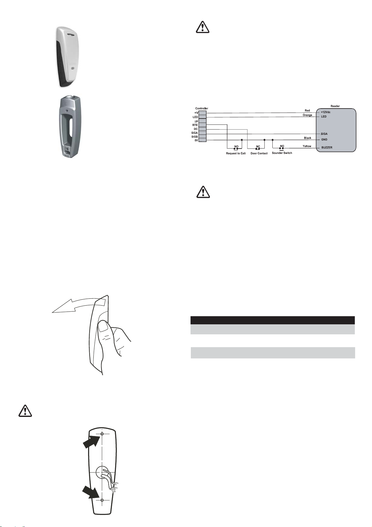
Wiring
1. Read the instructions before wiring.
2. The request to exit and door contact can be wired for 4-state if required.
Note
Using two readers, for in and out, on one door channel will require one reader to be powered separately.
See Technical Bulletin TB151 "How to Connect High-Current Readers to PAC Access Controllers"
1. Connect the wiring as indicated in the diagram to the socket. Check your circuit diagram for the colour
coding of the circuit wiring.
Connect the 0V reference and 0V (if provided in the power supply) to the ground (GND) Wire.
Connect the signal and optional wires.
Connect the LED wire.
Connect the +12Vdc wire last.
White
The reader outputs a PAC format suitable for PAC 202/512 access controllers. They are used in security
applications and can be installed in new installations or as an upgraded reader in existing proximity access
control systems. Each reader incorporates a LED which is controlled by the security system and provides
feedback to a person wishing to enter.
External Use
Mount the reader on a suitable external single gang surface mount box.
Make sure that the wire bundle to the reader has an IP rating of at least IP67.
Use warming pads if the temperature of the reader is expected to fall below -10ºC (14ºF).
Handling
Handle the reader with care. Do not damage/drop unit before installation.
Smart Mullion Reader Installation
1. Remove the cover by holding the unit as shown and pulling the cover from the top as illustrated.
2. Place the reader on the wall. Make sure the wires are not crushed.
3. Insert and hand tighten the screws.
4. Check that the reader is level before tightening the screws.
Excessive tightening of screws may deform the casing, resulting in a damaged unit.
THIS WILL VOID THE WARRANTY.
5. Replace the cover.
6. Power up the reader.
Note
The unit needs approximately 13 seconds to set up
before it can respond to a valid smart card.
Maintenance
Once installed the reader requires no maintenance
Troubleshooting
If the reader doesn't respond when a valid smart card is presented, check the following:
Symptom
LED is not lit
LED is orange/indeterminate
or buzzer sounds low
Reader doesn't respond
Possible Cause
No power to the reader
Voltage to the reader is below
minimum required level
Invalid card or card is faulty or
Wiring to the controller is faulty.
Check
Check the power supply to the reader.
Check the power supply to the reader
Check reader with another valid smart
card; if problem persists check wiring
2. If necessary, drill holes for the mounting screws in the wall or mounting box on which the reader unit will
be placed. Use the template provided. Alternately a back box can be used.
3. Place the controller and power supply cable through the grommit hole.
4. Drill the holes in the wall as indicated by the arrows.
Make sure that you don't drill through the cable.
62
45
If the problem still exists, uninstall the reader and send it back to the PAC. If the reader is within the warranty
period then another will be sent free of charge.
Warranty
Each reader comes with a 3-year warranty from the date of dispatch. The warranty is void if the instructions
contained within this document have not been adhered to.
 Loading...