

Page 1
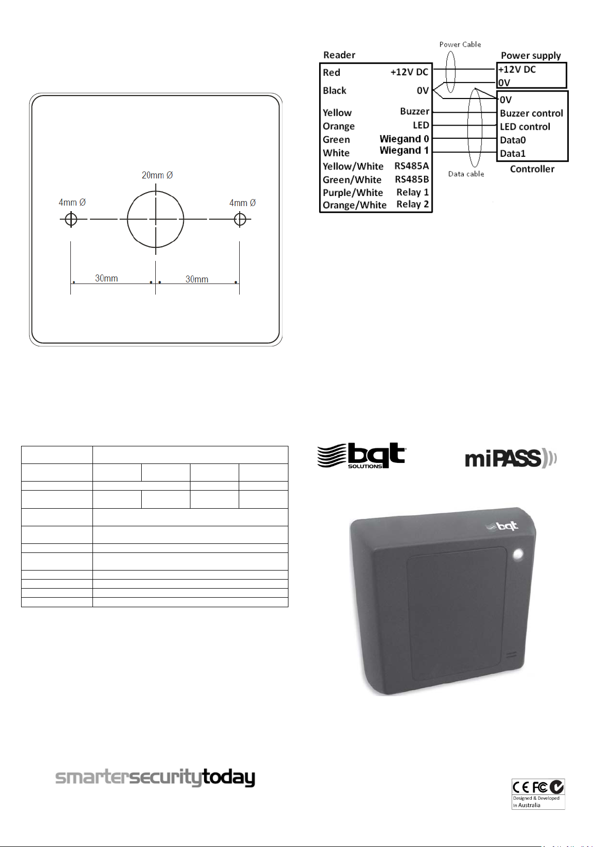
Drilling template
Output protocols
Wiegand 26-199 bit, RS485 or custom configuratio n (Model
dependent)
BT815-WG/
MiP5/CSN5
BT815-D/D2
BT815
BT815-BM
Power requirement
12V DC
6-18V DC
7-16V DC
Current
consumption
103mA (Avg)
157mA (Avg)
38mA (Avg)
45mA (Avg)
Read range
20-40mm (0.8”-1.6”) at 12V DC depends o n the type of card
used
Operating
temperature
-25’C to +65’C (-13’F to 149’F)
Relative humidity
90% max, operating non-condensing
Reader dimensions
Standard: 90mm(L) x 90mm(W) x 27mm(D) (3.54”x3.54”x1.06”)
Slim Line: 90mm(L) x 90mm(W) x 20mm(D) (3.54”x3.54”x0.79”)
Status LED
Green & Red
Audible tone
Internal and external buzzer control
Colour finish
Charcoal & Ivory
IP rating
IP65
AUSTRALIA & PACIFIC
EUROPE AND MIDD LE EAST
GREATER ASIA
5
INSTALLATION GUIDE
• 20mm (0.79”) diameter hole for wire entry
• 2 x 4 mm (0.16”) diameter holes for mounting screws
• Inner reader dimension is 88mm x 88 mm (3.47" x 3.47")
• Assemble reader outer dimension is 90mm x 90mm (3.54” x 3.54”)
• Reader corne r radius is 4mm (0.16”)
Wiring diagram
Specifications
145mA (Peak)
174mA (Peak)
80mA (Peak)
135mA (Peak)
Note:
• A shielded cable is recommended to be used. The shield is connected to controller 0V reference
• Maximum wieg and data cable length: 150 meters (500 feet)
• Buzzer and LED are activated when buzzer and LED line go below 2.5V.
• RS485 lines and Relay lines are only for optional use.
• Some models have additional wires/connectors which are not specified in the diagram above. These wires are for other
requirements. DO NOT connect them unless specified from BQT Solutions or a BQT authorized distributor. Any damage
caused by incorrect connection will void the warranty
• Terminate or insulate all un-used wires
Regulatory Information
C-Tick: This device is C-Tick complied.
CE: The device has passed all relevant tests and obtained CE approval.
FCC: This device complies with Part 15 of the FCC Rules. Operation is subject to the following two conditions: 1) this device
may not cause harmful interference and 2) this device must accept any interference received, including interference that
may cause undesired operation of the device.
Warning: This equipment has been tested and found to comply with the limits for a Class B digital device, pursuant to part
15 of the FCC rules. These limits are designed to provide reasonable protection against harmful interference in a residential
installation. This equipment generates uses and can radiate radio frequency energy and, if not installed and used i n
accordance with the instructions, may cause harmful interference to radio communications. However, there is no
guarantee that interference will not occur in a particular installation. If this equipment does cause harmful interference to
radio or television reception, which can be determined by turning the equipment off and on, the user is encouraged to try
to correct the interference by one or more of the following measures:
-Reorient or relocate the receiving antenna.
-Increase the separation between the equipment and receiver.
-Connect the equipment into an outlet on a circuit different from that to which the receiver is connected.
-Consult the dealer or an experienced radio/TV technician for help.
Any changes or modifications not expressively approved by BQT Solutions could void the user’s authority to operate this
equipment.
Information obtained in this document is subject to cha nge without notice.
For further technical i nformatio n, visit our website a t www.bqtsolutions.com or email
techsupport@ bqtsolutions.com.
Alternatively contact us at one of our global locations
BQT Solutions (Australia) Pty Limited
Level 1, 82 Waterloo Road
Macquarie Park, NSW 2113, Australia
Phone: +61 (0)2 8817 2800
Fax: +61 (0)2 8817 2811
Email: [email protected]
Copyright © 2012 BQT Solutions Limi ted. BQT Soluti ons and the BQ T solutions l ogo are regist ered trademarks of BQT Soluti ons (Australia ) Pty Ltd.
BQT Solutions (UK) Limited
Regal House, 70 London Road
Twickenham, TW1 3QS
United Kingdom
Phone: +44 (0)20 8622 4428
Fax: +44 (0)20 8622 4401
Email: [email protected]
BQT Solutions Singapore Office
Mediapolis
71 Ayer Rajah Crescent #03-03
Singapore 139951
Phone: +65 6220 7970
Fax: +65 6220 7656
Email: [email protected]
Series
Version4.1
Page 2
Installation
Problem
Troubleshooting steps
Power on rea der – reader does
1. Check connections
Power on rea der – reader keeps
1. Check buzzer line
Power on rea der – LED stays
green
1. Check LED line
Present a card to reader – a beep
1. Check whether the card has data encoded
Present a card to reader – no
1. Try a known working card
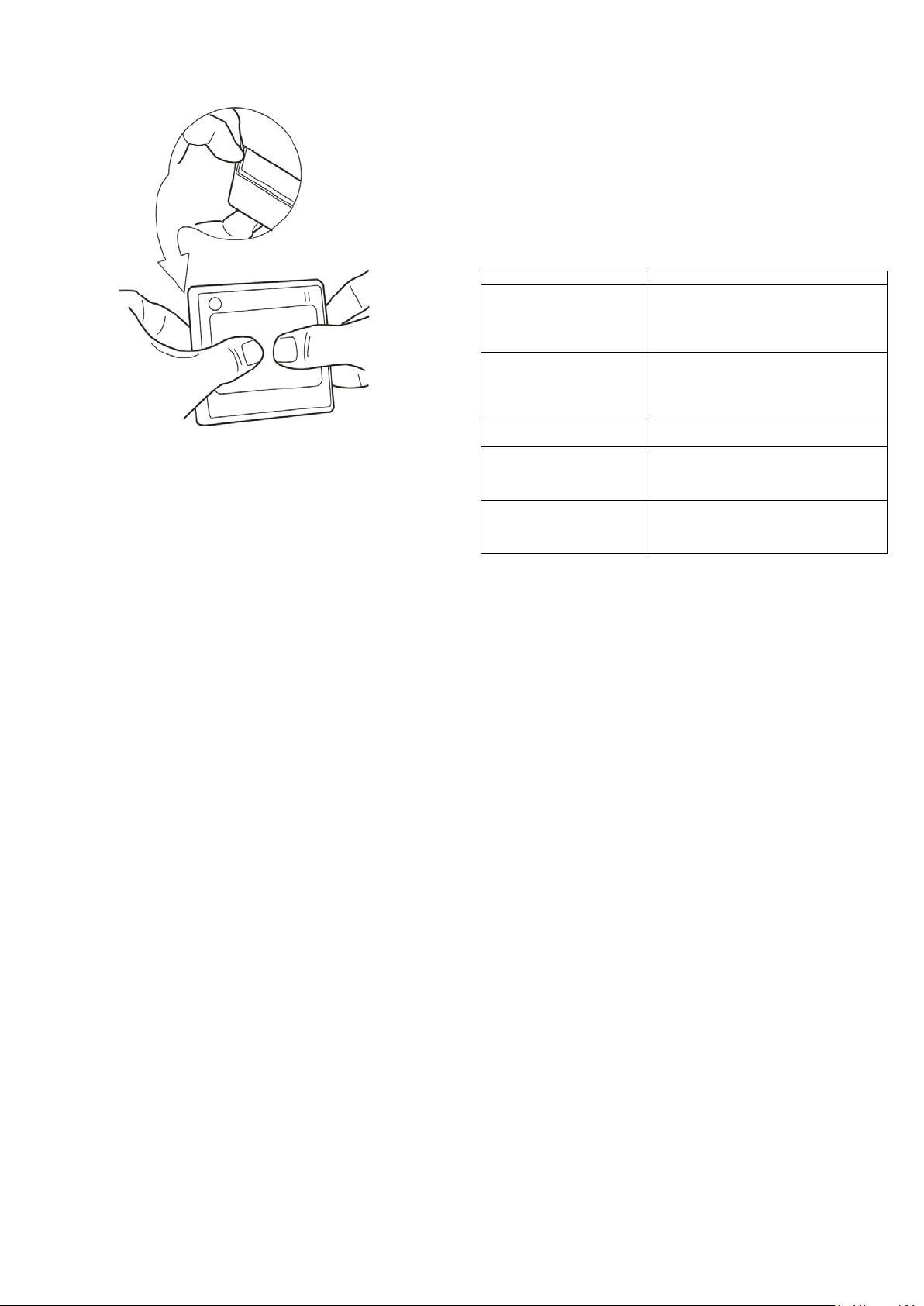
Remove the cover by holding the unit by the rim and pushing the reader
out with your thumbs.
External Use
• Make sure the wire bundle to the reader has an IP rating of at least IP65
Handling
• Handle the reader with care. DO NOT damage or drop unit before
installation. This will void the warranty.
• If the case is damaged, the reader may not be to the specified IP rating.
Replace the reader if the case is damaged.
Maintenance
• Once installed the reader requires no maintenance.
Troubleshooting
Note: DO NOT use a screw driver or other implement to remove cover
If necessary, drill holes in the wall for the mounting screws or mounting
box on which the reader unit will be placed. (Use the Drilling Template
provided overleaf).
1. Place the controller and power supply cable through the grommet hole.
2. Drill the holes as indicated in the template.
Note: Make sure that you don't drill through the cable.
Wire connection
Note:
Power to the unit is provided from the listed control unit or from a
separately UL listed 12V DC power-limited, access control power source.
DO NOT supply power during installation.
Wiring methods shall be in accordance with the Electrical wiring regulation
in your country / region.
Check your circuit diagram for the colour coding of the circuit wiring. The
reader can be damaged beyond repair if the wiring is connected incorrectly.
This will void the warranty.
1. Connect the 0V wire to the power 0V line;
Note: The 0V line of all power supplies must be connected to a common 0V reference
point.
2. Connect the Wiegand data wires;
3. Connect the Buzzer and LED wires;
4. Connect 12V DC wire;
5. Place reader on the wall (Make sure the wires are not crushed. This
will void the warranty if damage occurs)
6. Insert and hand tighten the screws;
7. Check that the reader is level before tightening the screws;
Note: Excessive tightening of screws may deform the casing, resulting in a damaged
unit. This will void the warranty.
8. Turn on the 12V DC power to power up reader.
9. Allow 5 – 10 seconds for reader to finish initialization (depends on the
application). Make sure reader is functioning correctly according to
the application specification.
not start up
beeping
is heard but reade r does not
output any data
response from reader
If the proble m still persists, please contact your dis tributor for technical support.
2. Check the voltage a t the reade r
3. Check the current capability of the powe r
supply
2. Check the voltage a t the reade r
3. Check the current capability of the powe r
supply
2. Check the wiegand connection to controller
3. Check the voltage level on wiegand data lines
2. Check if the reader requires to be configured
with a confi guration card
Warranty
Unless specified otherwise, the Company warrants to the Customer that’
BQT Solutions Branded Products’ (excluding third party products and
software) are covered by a return to base warranty on defects in materials
and workmanship affecting normal use for a period of the Warranty offered
under the Standard Terms and Conditions of Sale from BQT invoice date
(‘Standard Warranty’)
This standard warranty does not cover damage, fault, failure or malfunction
due to external causes including; accident, misuse, problems with electrical
power, servicing not authorised by the Company, usage and/or storage
and/or installation not in accordance with Product instructions, failure to
perform required preventative maintenance, normal wear and tear, act of
God, fire, flood, war, any violent or similar occurrence; any attempt by any
person other than Company personnel or any person authorised by the
Company to repair or support the Products and problems caused by use of
parts and components not supplied by the Company. The standard warranty
does not cover any items that are in one or more of the following categories:
software; external devices; accessories or parts added to the product after
the product has been shipped from BQT Solutions.
During the warranty, period beginning on the invoice date, the Company will
repair or replace faulty products (at its absolute discretion) returned to its’
factory. The Customer must prepay shipping and transportation costs and
insure the shipment or accept the risk of loss or damage during such
transportation.
The Customer shall be solely responsible for determining suitability for use
and the Company will, in no event, be liable in this respect. This standard
warranty is given in place of all warranties, conditions, terms, undertakings
and obligations implied by statute, common law, trade usage, and course of
dealing or otherwise including warranties or conditions of merchantability,
fitness for purpose, satisfactory quality and / or compliance with description,
all of which are hereby excluded to the fullest extent permitted by law.
Page 3
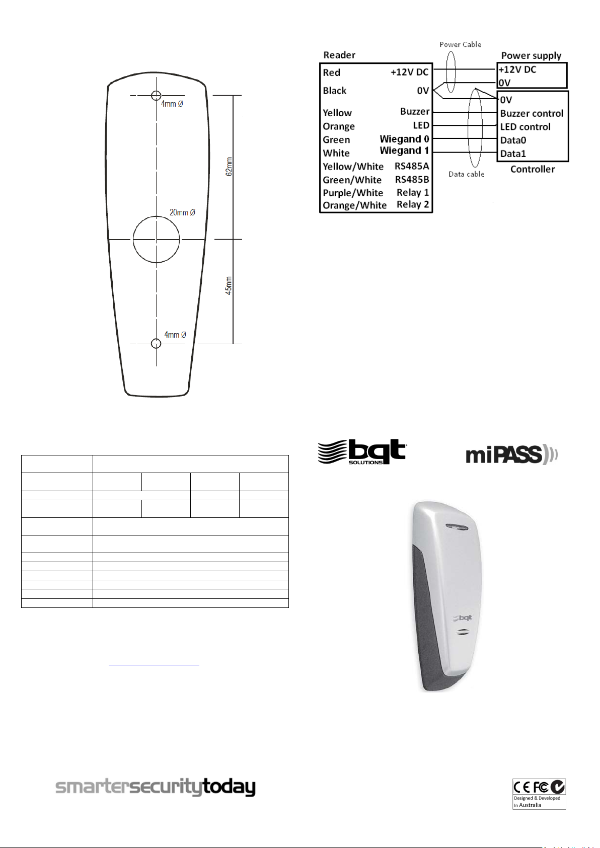
Drilling template
Output protocols
Wiegand 26-199 bit, RS485 or custom configuratio n (Model
dependent)
BT900-WG/
miP9 / CSN9
BT900-D
BT900
BT900-BM
Power requirement
12V DC
6-18V DC
7-16V DC
Current
consumption
103mA (Avg)
135mA (Avg)
38mA (Avg)
45mA (Avg)
Read range
20-40mm (0.8”-1.6”) at 12V DC depends o n the type of card
used
Operating
temperature
-25’C to +65’C (-13’F to 149’F)
Relative humidity
90% max, operating non-condensing
Reader dimensions
140mm(L) x 45mm(W) x 32mm(D) (5.51”x1.77”x1.26”)
Status LED
Green & Red
Audible tone
Internal and external buzzer control
Colour finish
Two toned – Silver & Charcoal
IP rating
IP65
AUSTRALIA & PACIFIC
EUROPE AND MIDD LE EAST
GREATER ASIA
9
INSTALLATION GUIDE
• 20mm (0.79”) diameter hole for wire entry
• 2 x 4 mm (0.16”) diameter holes for mounting screws
• Minimum reade r dimensions are 140mm x 45 mm (5.51" x 1.77")
Wiring diagram
Specifications
145mA (Peak)
155mA (Peak)
80mA (Peak)
135mA (Peak)
Note:
• A shielded cable is recommended to be used. The shield is connected to controller 0V reference
• Maximum wie gand data cable length: 150 meters (500 feet)
• Buzzer and LED are activated when buzzer and LED line go below 2.5V.
• RS485 lines and Relay lines are only for optional use
• Some models have additional wires/connectors which are not specified in the diagram above. These wires are for other
requirements. DO NOT connect them unless specified from BQT Solutions or a BQT authorized distributor. Any damage
caused by incorrect connection will void the warranty
• Terminate or insulate all un-used wires
Regulatory Information
C-Tick: This device is C-Tick complied.
CE: The device has passed all relevant tests and obtained CE approval.
FCC: This device complies with Part 15 of the FCC Rules. Operation is subject to the following two conditions: 1) this device
may not cause harmful interference and 2) this device must accept any interference received, including interference that
may cause undesired operation of the device.
Warning: This equipment has been tested and found to comply with the limits for a Class B digital device, pursuant to part
15 of the FCC rules. These limits are designed to provide reasonable protection against harmful interference in a residential
installation. This equipment generates uses and can radiate radio frequency energy and, if not installed and used in
accordance with the instructions, may cause harmful interference to radio communications. However, there is no
guarantee that interference will not occur in a particular installation. If this equipment does cause harmful interference to
radio or television reception, which can be determined by turning the equipment off and on, the user is encouraged to try
to correct the interference by one or more of the following measures:
-Reorient or relocate the receiving antenna.
-Increase the separation between the equipment and receiver.
-Connect the equipment into an outlet on a circuit different from that to which the receiver is connected.
-Consult the dealer or an experienced radio/TV technician for help.
Any changes or modifications not expressively approved by BQT Solutions could void the user’s authority to operate this
equipment.
Information obtained in this document is subject to cha nge without notice.
For further technical i nformatio n, visit our website a t www.bqtsolutions.com or email
techsupport@ bqtsolutions.com
.
Alternatively contact us at one of our global locations
BQT Solutions (Australia) Pty Limited
Level 1, 82 Waterloo Road
Macquarie Park, NSW 2113, Australia
Phone: +61 (0)2 8817 2800
Fax: +61 (0)2 8817 2811
Email: [email protected]
Copyright © 2012 BQT Solutions Limi ted. BQT Soluti ons and the BQ T solutions l ogo are regist ered trademarks of BQT Soluti ons (Australia ) Pty Ltd.
BQT Solutions (UK) Limited
Regal House, 70 London Road
Twickenham, TW1 3QS
United Kingdom
Phone: +44 (0)20 8622 4428
Fax: +44 (0)20 8622 4401
Email: [email protected]
BQT Solutions Singapore Office
Mediapolis
71 Ayer Rajah Crescent #03-03
Singapore 139951
Phone: +65 6220 7970
Fax: +65 6220 7656
Email: [email protected]
Series
Version4.1
Page 4
Installation
Problem
Troubleshooting steps
Power on rea der – reader does
1. Check connections
Power on rea der – reader keeps
1. Check buzzer line
Power on rea der – LED stays
green
1. Check LED line
Present a card to reader – a beep
1. Check whether the card has data encoded
Present a card to reader – no
1. Try a known working card
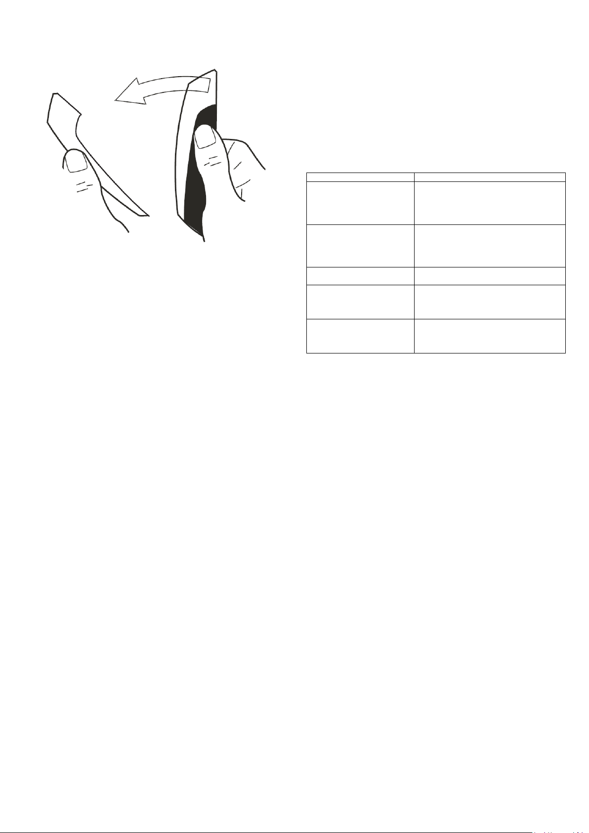
Remove the cover by holding the unit as shown and pulling the cover from
the top as illustrated
External Use
• Make sure the wire bundle to the reader has an IP rating of at least IP65
Handling
• Handle the reader with care. DO NOT damage or drop unit before
installation. This will void the warranty.
• If the case is damaged, the reader may not be to the specified IP rating.
Replace the reader if the case is damaged.
Maintenance
• Once installed the reader requires no maintenance.
Troubleshooting
Note: DO NOT use a screw driver or other implement to remove cover
If necessary, drill holes in the wall for the mounting screws or mounting
box on which the reader unit will be placed. (Use the Drilling Template
provided overleaf).
1. Place the controller and power supply cable through the grommet hole.
2. Drill the holes as indicated by the arrows.
Note: Make sure that you don't drill through the cable.
Wire connection
Note:
Power to the unit is provided from the listed control unit or from a
separately UL listed 12V DC power-limited, access control power source.
DO NOT supply power during installation.
Wiring methods shall be in accordance with the Electrical wiring regulation
in your country / region.
Check your circuit diagram for the colour coding of the circuit wiring. The
reader can be damaged beyond repair if the wiring is connected incorrectly.
This will void the warranty.
1. Connect the 0V wire to the power 0V line;
Note: The 0V line of all power supplies must be connected to a common 0V reference
point.
2. Connect the Wiegand data wires;
3. Connect the Buzzer and LED wires;
4. Connect 12V DC wire;
5. Place reader on the wall (Make sure the wires are not crushed. This
will void the warranty if damage occurs)
6. Insert and hand tighten the screws;
7. Check that the reader is level before tightening the screws;
Note: Excessive tightening of screws may deform the casing, resulting in a damaged
unit. This will void the warranty.
8. Turn on the 12V DC power to power up reader.
9. Allow 5 – 10 seconds for reader to finish initialization (depends on the
application). Make sure reader is functioning correctly according to
the application specification.
not start up
beeping
2. Check the voltage a t the reade r
3. Check the current capability of the powe r
supply
2. Check the voltage a t the reade r
3. Check the current capability of the powe r
supply
is heard but reade r does not
output any data
response from reader
If the proble m still persists, please contact your dis tributor for technical support.
2. Check the wiegand connection to controller
3. Check the voltage level on wiegand data lines
2. Check if the reader requires to be configured
with a confi guration card
Warranty
Unless specified otherwise, the Company warrants to the Customer that’
BQT Solutions Branded Products’ (excluding third party products and
software) are covered by a return to base warranty on defects in materials
and workmanship affecting normal use for a period of the Warranty offered
under the Standard Terms and Conditions of Sale from BQT invoice date
(‘Standard Warranty’)
This standard warranty does not cover damage, fault, failure or malfunction
due to external causes including; accident, misuse, problems with electrical
power, servicing not authorised by the Company, usage and/or storage
and/or installation not in accordance with Product instructions, failure to
perform required preventative maintenance, normal wear and tear, act of
God, fire, flood, war, any violent or similar occurrence; any attempt by any
person other than Company personnel or any person authorised by the
Company to repair or support the Products and problems caused by use of
parts and components not supplied by the Company. The standard warranty
does not cover any items that are in one or more of the following categories:
software; external devices; accessories or parts added to the product after
the product has been shipped from BQT Solutions.
During the warranty, period beginning on the invoice date, the Company will
repair or replace faulty products (at its absolute discretion) returned to its’
factory. The Customer must prepay shipping and transportation costs and
insure the shipment or accept the risk of loss or damage during such
transportation.
The Customer shall be solely responsible for determining suitability for use
and the Company will, in no event, be liable in this respect. This standard
warranty is given in place of all warranties, conditions, terms, undertakings
and obligations implied by statute, common law, trade usage, and course of
dealing or otherwise including warranties or conditions of merchantability,
fitness for purpose, satisfactory quality and / or compliance with description,
all of which are hereby excluded to the fullest extent permitted by law.
 Loading...