

Page 1

BQ351
MODBUS IO DEVICE
USER MANUAL
Document Version 1.2.0
Page 2

BQ351 Modbus IO Device User Manual
Content
Content 2
About Device 3
Device Properties 3
Device Layout 4
Sample Connection 6
DIP Switch and Address Settings 7
DIP Switch Modes 7
Supported Modbus Commands 8
Register - Coil Table 9
Device Settings with “Modbus Device Manager” 9
Settings Mode 9
www.bqtek.com Page 2 / 10
Page 3

BQ351 Modbus IO Device User Manual
About Device
BQ351 is an Modbus IO device with 8 relay output and 8 digital input. Device supports Modbus RTU over
RS485.
Holding register, Input Register and Coils commands of Modbus RTU is supported.
Device Modbus address can be set by user. Also baudrate of device is adjustable. But 8 Bit , No Parity
and 1 Stop bit si fixed. Device addresses between 1 and 14 can be set from switches on device. Also you
can set address greater than 14; but you must use device manager program for this.
Device Properties
Product Code
BQ351
Product Name
Modbus Digital IO Device
16 Channel (8 Relay, 8 Digital Input)
Relay Output
8 Panasonic Relay
5A 277V AC / 3A 30V DC Capacity
Digital Input
8 Dry Contact Digital Input
Power Need
24V DC
Enclosure
Rail Type
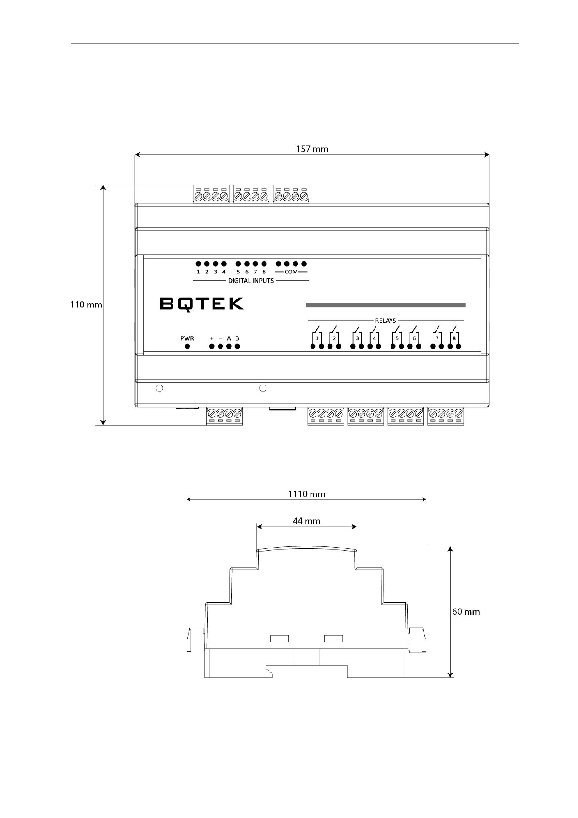
157 x 90 x 60 mm
(Also suitable for wall mounth)
Terminal
Plug-in terminal (3.81mm)
Protocol
Modbus RTU over RS485
Factory defults for communication is 9600 Baud, 8 Bit, No Parity, 1 Stop Bit and Modbus address is 1.
You can change modbus address with DIP switch or with Modbus Device Manager Software. Also this
default 9600 baud can be adjustable.
www.bqtek.com Page 3 / 10
Page 4
BQ351 Modbus IO Device User Manual
Device Layout
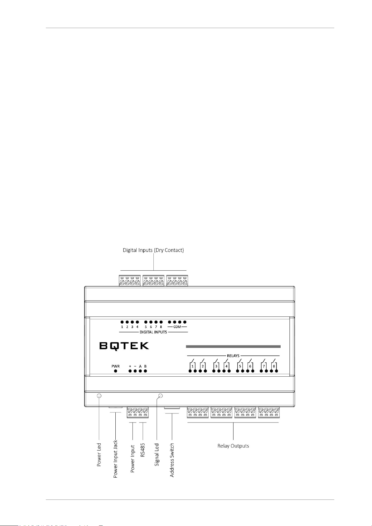
You can see device layout at the picture below. Terminals are screew type terminals. You can also find
descriptions about device connections on the device enclosure.
www.bqtek.com Page 4 / 10
Page 5
BQ351 Modbus IO Device User Manual
Power Supply
Device works with 24V DC power. When all relays are on max current is about 350mA. Connect + and -
terminals to power supply.
RS485
A and B terminals are for RS485 communication. Please obey RS485 cabeling rules and use suitable cable
for RS485
Dip Switch
Dip switches are for device settings mode and for adjusting and address. Please read this document for
usage of dip switch.
Relay Outputs
Device has 8 relay output. Relays have only Normally Open (NO) contacts. Relays are Panasonic ALDP124
relays in device. This relays are for 5A 277V AC / 3A 30V DC Capacity. Please review ALDP124 documents
from panasonic for detailed information. For extra capacity and for capacitive and inductive loads use
external relays. Relay outputs are normally open contacts of relays.
Digital Inputs
Device has 8 digital input. Digital inputs are dry contact. If COM pin out and digital input pin is short
circuit it shows inpu is ON
Leds
Power led shows device is working. Busy led means there is an communication over RS485. Each relay
led means status of relay. Also in device settings mode Power led and busy light is on together during
power on. Detailed information about settings are explained next pages in document.
www.bqtek.com Page 5 / 10
Page 6
BQ351 Modbus IO Device User Manual
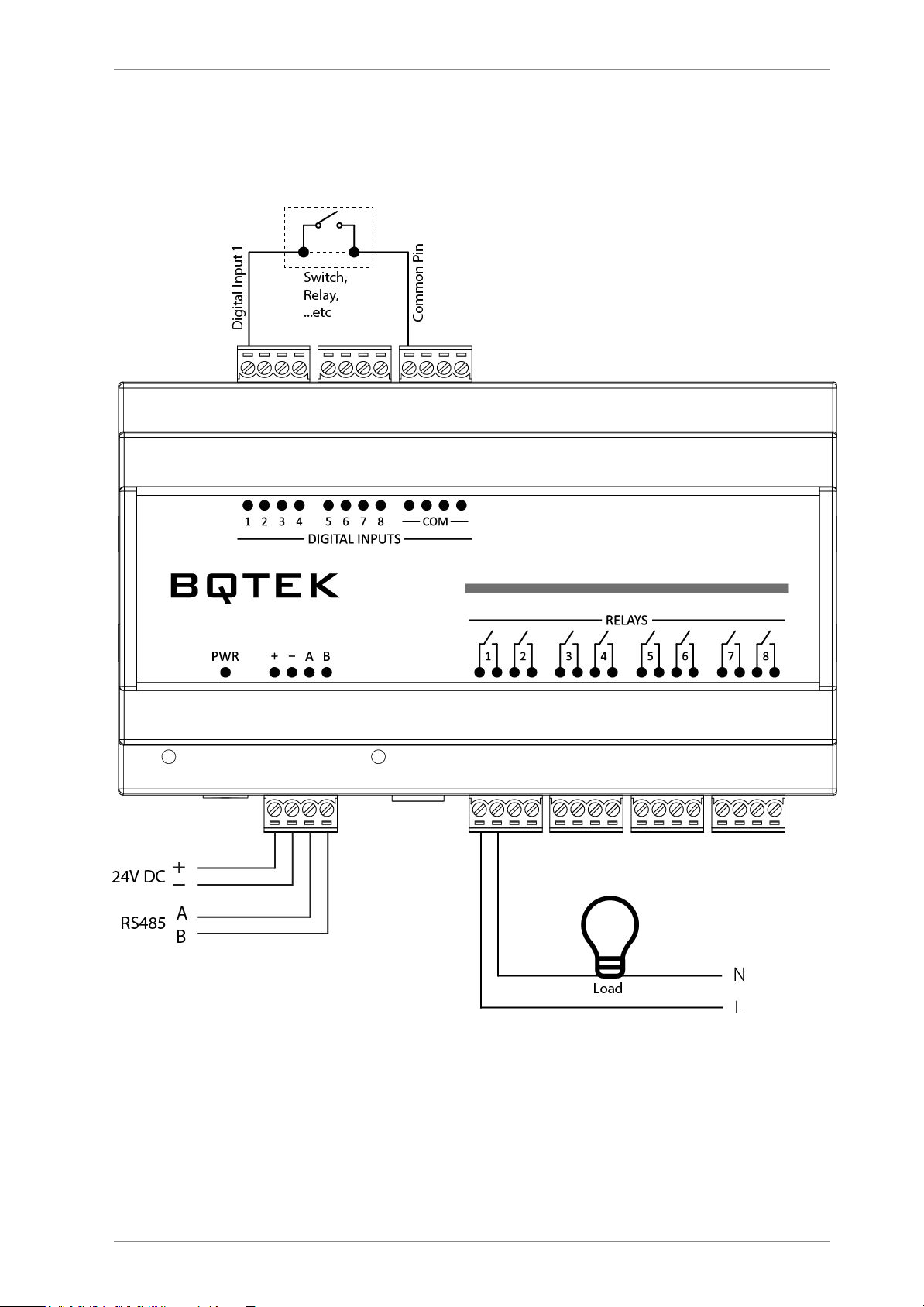
Sample Connection
You can see a sample connection in picture below.
www.bqtek.com Page 6 / 10
Page 7
BQ351 Modbus IO Device User Manual
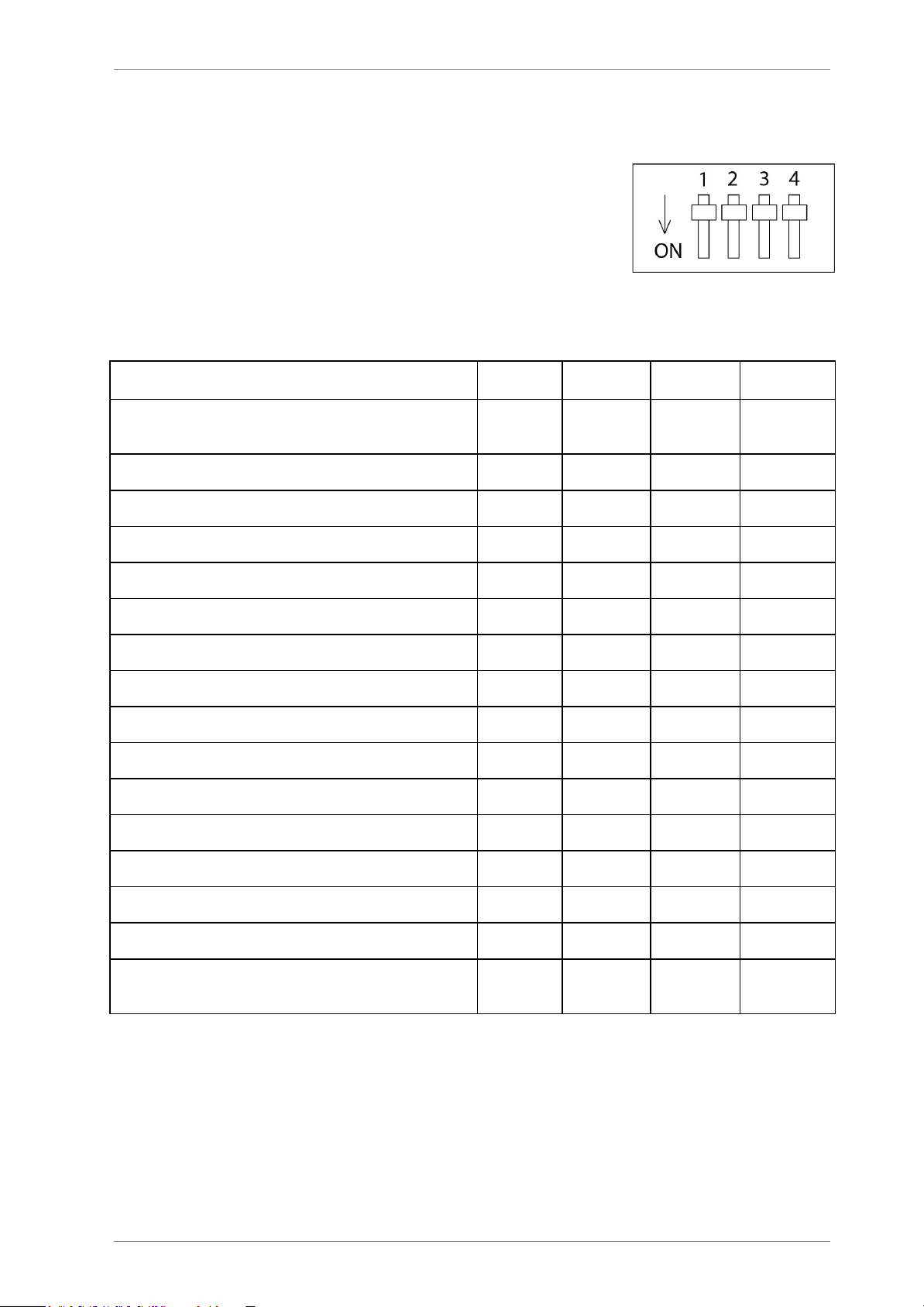
DIP Switch and Address Settings
You can change device modbus address between 1-14 with DIP switch on
device. Address greater than 14 can be set from Modbus Device manager
software. Making changes and applying changes also needs DIP switch
settings.
DIP Switch Modes
Description
1 2 3
4
Settings Mode
(Changing device settings from RS485)
OFF
OFF
OFF
OFF
Address 1
ON
OFF
OFF
OFF
Address 2
OFF
ON
OFF
OFF
Address 3
ON
ON
OFF
OFF
Address 4
OFF
OFF
ON
OFF
Address 5
ON
OFF
ON
OFF
Address 6
OFF
ON
ON
OFF
Address 7
ON
ON
ON
OFF
Address 8
OFF
OFF
OFF
ON
Address 9
ON
OFF
OFF
ON
Address 10
OFF
ON
OFF
ON
Address 11
ON
ON
OFF
ON
Address 12
OFF
OFF
ON
ON
Address 13
ON
OFF
ON
ON
Address 14
OFF
ON
ON
ON
Get Address from Settings
(Apply Settings that made from RS485)
ON
ON
ON
ON
Device default baudrate is 9600 baud. (8bit, No Parity, 1 Stop) Adjust any address between 1..14 and
easly start to use. For other baudrates and addresses read the document.
www.bqtek.com Page 7 / 10
Page 8

BQ351 Modbus IO Device User Manual
Supported Modbus Commands
Device supports listed commands below. These are standard Modbus RTU commands. Most PLC, HMI
and Scada applications supports this commands.
Command Description
Command (HEX)
Read Holding Register
03
Read Input Register
04
Read Coils
01
Read Discrete Inputs
02
Write Multible Register
10
Write Single Register
06
Write Multible Coil
0F
Write Single Coil
05
Writing 1 value will Set relay ON and writing 0 value Sets relay OFF. You can find register and coil
adresses in this document.
www.bqtek.com Page 8 / 10
Page 9
BQ351 Modbus IO Device User Manual
Register - Coil Table
Global Modbus specifitions says first address is 1 but sometimes some PLC or scada applications accept
0 as first modbus register address. Our documents are prepared for based 1. If your plc accept 0 based
register addresses; you can decrease -1 from the addresses below.
Relay ID
Register
Number
Coil
Number
Relay 1 1 1
Relay 2 2 2
Relay 3 3 3
Relay 4 4 4
Relay 5 5 5
Relay 6 6 6
Relay 7 7 7
Relay 8 8 8
Input ID
Register
Number
Coil
Number
Input 1 9 9
Input 2
10
10
Input 3
11
11
Input 4
12
12
Input 5
13
13
Input 6
14
14
Input 7
15
15
Input 8
16
16
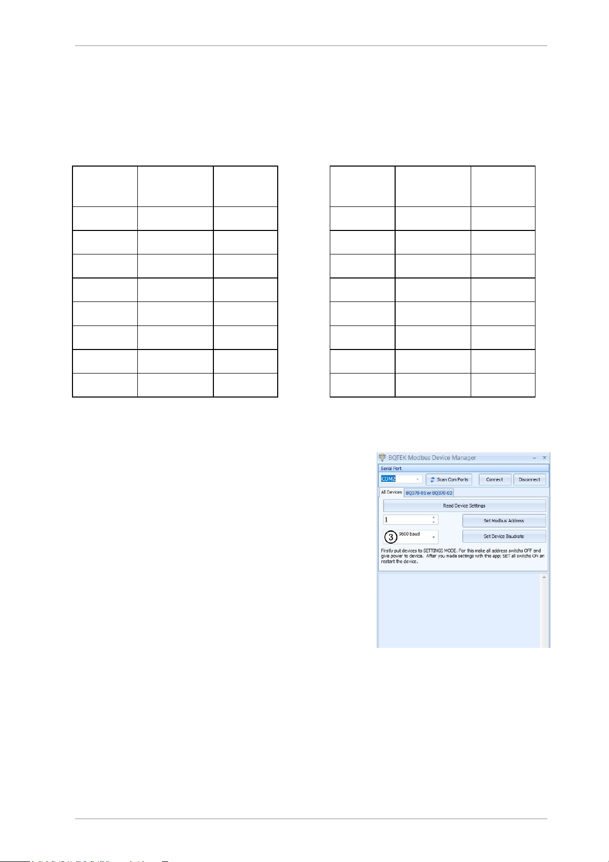
Device Settings with “Modbus Device Manager”
Device default baudrate is 9600 baud. (8 Bit, No parity, 1 Stop)
You can adjust device address from DIP switch and you can start
using device with 9600 baud easly.
But sometimes you can need other baudrates or you can need
addresses greater then 14. In this situation you can change
device settings with RS485.
For this you must put device to “Settings Mode”. After than you
can change device settings with our “Modbus Device Manager”
application. Also experts users can use Modbus RTU protocol for
changing settins instead of Modbus Device Manager. Expert
users can reach detailed information about our web page or can
contact with us.
Settings Mode
For making settings from “Modbus Device Manager”; you must put device settins mode. Power off
device and put all DIP switchs to “OFF” position. Now you can give power to device. You will see power
and busy led is ON together; this shows device is in “Settings Mode”
Now connect RS485 to computer and use “Modbus Device Manager” application for reading or changing
device settings.
After making changes you must exit from “Settings Mode” For this set all DIP switchs ON position and
reset the power of device.
www.bqtek.com Page 9 / 10
Page 10

BQ351 Modbus IO Device User Manual
Supported baudrates are 2400, 4800, 9600, 14400, 19200, 28800 and 38400 baud.
If you dont have RS485 port on your computer you can use USB-RS485 converter devices for this.
Also as explained before experts users can change settings from RS485 with Modbus RTU commands.
You can find information about this in our web page.
www.bqtek.com Page 10 / 10
 Loading...