

Page 1
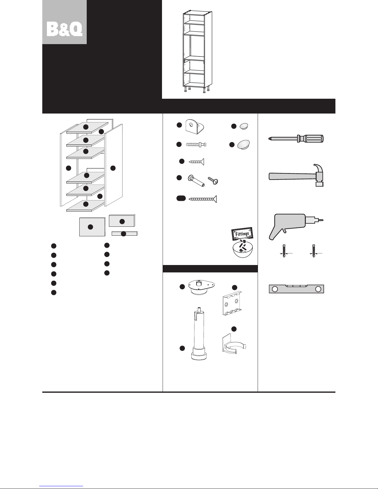
2 x Back Panel
2 x Rail*
2 x Oven Spacer Panel*
2 x Oven Support Rails*
1 x RH Side
1 x LH Side
1 x Top Panel*
1 x Base Panel*
2 x Shelf (Fixed)*
2 x Shelf*
Cross Head Screwdriver
Drill
Level
3mm
Drill Bit
5mm
Drill Bit
1
2
3
4
5
6
Panels Hardware
ASSEMBLY GUIDE
Minimum Tools required
Hammer
2 x
A
18 x
C
15mm
8 x
B
4 x
D
44 x
F
12 x
G
7
APPLIANCE
Housing
8
9
Tall
12
3
4
5
5
6
6
7
8
9
7
6 x
DD
30 mm
10
10
Before you Start …
WARNING: Installation should be performed by a competent person only. This product could
be dangerous if incorrectly installed. All assembly fittings except legs and shelf pegs have
been pre-inserted. If any are missing or there is a problem with the panels, please call the
Helpline on 01769 575500 and our team will get things sorted.
Cleaning – Use mild soap and water only. Do not use abrasive cleaners.
Legs
4 x
S
2 x
U
4 x
T
2 x
V
Please use scissors to open the
bag of fittings and then empty
the contents into a bowl, so
that they do not get lost!
Hinges Supplied Separately
*Supplied in separate Shelf Pack.
To protect your kitchen doors from any
excess heat emitted by your oven, it is
strongly recommended that an appropriate
Oven Heat Deflector Kit is fitted around
the oven aperture in this unit. Suitable kits
are available from B&Q and details can be
found in the kitchen price list.
Page 2
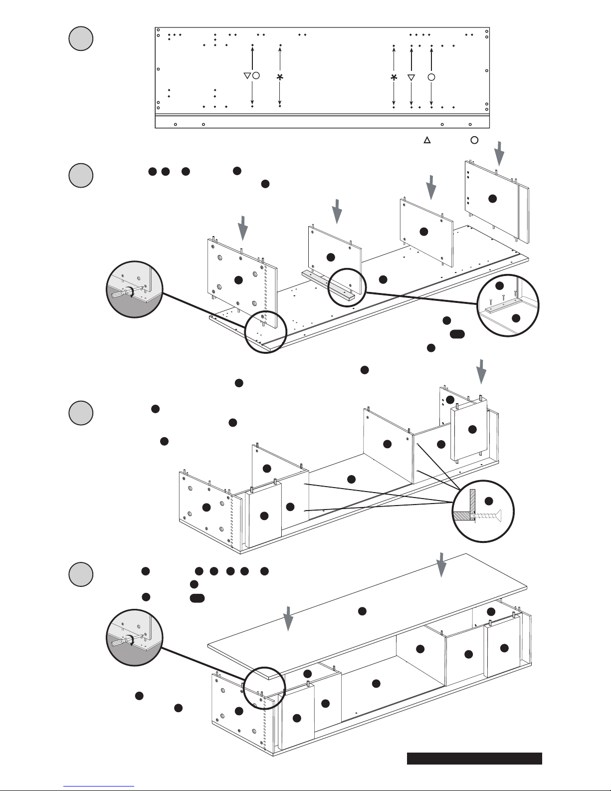
Drawing A: For oven housing openings, 600 = 900= 1000=
*
TOP OF CABINET
BASE OF CABINET
LH SIDE SHOWN
1
Now affix your cabinet legs
Cut panel to required size then fit to
grooves, secure with screws to fixed shelf.
Fit 2 x panel
Fit panels , & to panel
See ‘Drawing A’ for spacing of Panel
For appropriate oven sizes
2
3 4
5
2
3
4
5
5
C
7
3
4
5
5
5
LH SIDE
8
2
3
4
5
5
7
7
8
8
C
2
7
7
8
8
1
Note: Actual oven sizes
will vary, and you should refer to
the Appliance Manufacturers’ fitting
instructions to correctly fix your appliance.
Tighten metal cams
Now, add 1 x
secure with 3 x
to panel
DD
10
2
2
5
Fit Panel to panels , , , & .
Fit remaining panel
to panel with 3 x screws
1 3 4 5 7 8
DD
10
1
2
3
4
Fitting Lay-on drawers below an oven, in this unit, 2 x Panel should be
replaced by 4 x spare brackets , due to space restrictions.
10
A
Now fit oven spacer
panels , if required,
on top of panel to
raise the oven if it
is sitting too low in
the unit.
9
5
CSS1127 01/10
Page 3
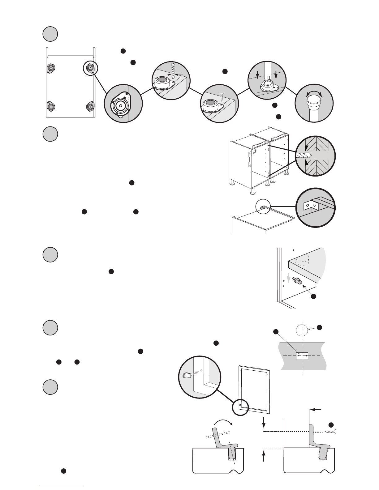
To fit legs, turn unit upside down
Fitting of Legs
Care should be taken when fitting legs and fitting to wall as Unit will be heavy
Cabinet
Underside
Position as shown,
lip on underside of side
panel .
Ensure screwhole is not
over panel join.
1
Drill pilot holes
3mm x 3 positions
3mm
Secure with screw
x 3 positions
Push
adjustable leg, into
leg boss
S
C
S
T
5
Rotate to adjust
height
Lay plinth panel in front of cabinet legs. Position plinth clip plate opposite front
cabinet legs. Secure with 2 x screws .
Slide into . Stand plinth up.
C
U
V
T
U
U
Fully insert the shelf pegs , at required position, (the back of the plastic collar must
finish flush with the face of the side panel). Rest the shelf on the pegs, and line up with
the plastic inserts. Now tap down firmly to secure.
NOTE: To remove the shelf, gently tap up and take out, push shelf peg in turn anticlockwise
with a screwdriver and pull out.
B
B
Supplied in Hinge Packs For Inset Doors and Frames only
Insert the metal frame brackets, at an angle, into the
holes in the back of the frame, and then straighten
them up, to grip the holes, before fitting the frame.
Carefully push the frame (with brackets) onto the front
of the cabinet, and adjust to the correct position.
Finally, secure the frame brackets to the cabinet with
screws (supplied in hinge pack).
unit
frame
C
C
Shelf Fitting
6
7
To fit plinths
8
Frame Fitting
9
All legs are pre-set at 150mm height.
Rotate to adjust up and down, to level the unit.
Drill a 5mm hole through both side panels.
Join together using joining bolts .
To Fit to wall, drill 3mm pilot hole into side panel of cabinet.
Fix 2 x bracket using 2 x screws
Levelling, Joining & Fitting to Wall
A
C
D
Wall Fitting not supplied Use appropriate fittings to secure cabinet
to wall (depending on wall type).
Page 4
CSS1127 01/10
Drawer Fitting Refer to drawer assembly guide with the drawer pack.
Handles Position as required.
NOTE: care should be taken when drilling for the handle so as not to drill in to the shelf.
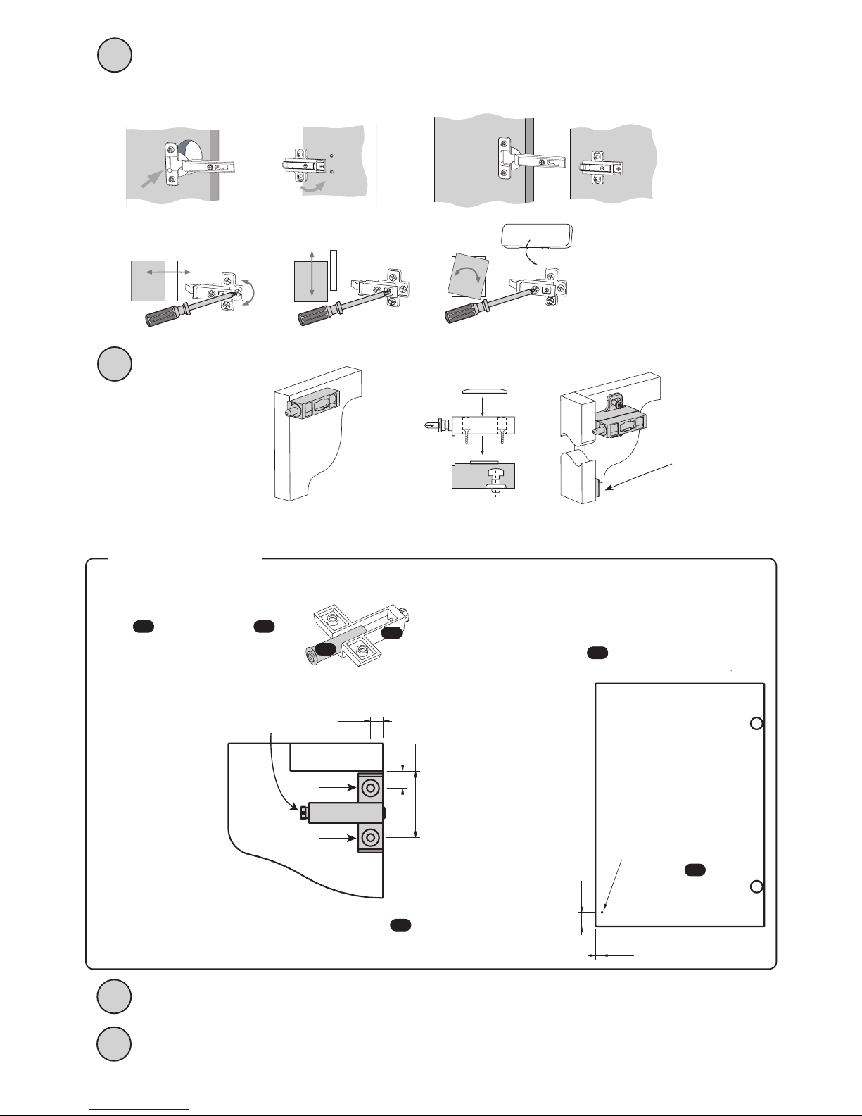
Soft Closer
Lay on
Frame
Fit to side panel with
2 x scews supplied
Fit to top hinge holes in side
panel opposite top hinge.
Insert Door Hinge into
rear recess in door
Affix Hinge Plate
on cabinet
Now, Clip Hinge onto Hinge Plate
Turn screws as shown to adjust door position
After adjustment is
complete apply cover plate
Door Hinges
mounting plate for
Inset Doors Only
Fixing of Magnetic Catch
First, carefully push the magnetic
catch , into the holder ,
as shown, until it clips onto the
adjustment screw at the end.
TOP RAIL
43mm
11mm
8mm
15mm screw fixing
adjustment screw
Fixing of Strike Plate
Using a 3mm drill bit, carefully drill a hole in the door,
as shown, approximately 10mm deep.
Now tap the strike plate into this hole, and close
the door.
LH hung wall door shown
3mm hole drilled
for metal striking
plate
20mm
43mm
The door should be
pushed onto the
magnetic catch,
to close it. Then,
to open the door,
simply push the
door again, and
release, and the
door should open.
If the door does
not open smoothly,
then it may require
further adjustment
of the hinges.
This section details all
options available. You
should follow the details
that refer to the system
you have purchased.
10
11
12
13
Fit the door
stop at the
bottom of
the frame, as
required
Push-to-open only:
ARAS
AT
AS
AR
AT
This is now ready to be fitted to the unit.
Carefully mark holes
for fixing the holder,
in the positions
shown, and using a
3mm drill bit, drill
approximately 5mm
deep.
Once fitted, use the adjustment screw to fix catch
in the optimum position.
Then fix the complete
magnetic holder to the
side panel, as shown.
AS
 Loading...