


1
Standard functions
-
Disabling the ring with light signal (the video handset
is still activated with all its functions), in the OPHERA
model only.
- Door open warning light.
- Warning that porter switchboard is trying to get in
t
ouch.
- Doorbell input.
- Possibility to route the call from 3 externally located
buttons to one video intercom.
- Distinctive ringing depending on where the call is
m
ade from (entry panel, doorbell, porter switchboard,
intercom unit).
- Call note type can be programmed to distinguish
between a call made from the entry panel (4 melodies)
and the doorbell (4 melodies).
-
Number of rings announcing the call can be programmed from the entry panel (the doorbell note is
not programmable).
- Call can be rerouted to another receiver.
If the user called does not answer, the call can be
rerouted to another receiver by programming with
MPP/300LR or PCS/300.
- Adjusting the volume of the ring to 3 levels.
Hands-free operation
When a call is made from the entry panel, press the
button to initiate communication, the LED light.
T
o end communication, press the button again,
the LED goes off.
If you wish to interrupt a communication temporarily
d
uring a conversation, press the button ( in
the OPHERA/B model), the LED flashes.
To restore communication press ( in the
OPHERA/B model), the LED goes of
f.
Talk-listen operation
When a call is made from the entry panel, press the
b
utton to initiate communication, the LED light.
Press down the button ( in the OPHERA/B
model) to speak with the entry panel.
Release the button ( in the OPHERA/B
model) to listen,the LED light.
To end communication, press the button , the
LED goes off.
Entry panel selection in installations with a number of entry panels
With the system off, turn on the monitor by pressing
the entry panel activation button . Press again to
switch between entry panels.
Alarm
The alarm is sent each time any remote device connected to the AL input of the M1 terminal block is activated.
This warning takes priority over all the others.
02.2009/2482-7402
OPHERA US
OPHERA US B
WARNINGS FOR THE USER
- In the case of breakdown or modification of the
apparatus of the system (such as power supp
lier...) please contact a specialized maintenan-
ce service.
OPHERA HANDS-FREE COLOUR
VIDEO HANDSET
O
PHERA hands-free colour video handset can be
used with video entry systems series 300, X2 and X1.
It must installed in a PHI dedicated rectangular
embedding box.
This appliance has a moveable part that can be tilted
o
utwards by 16° (fig. 1).
The video handset is equipped for the insertion of a
provided button accessory, which allows the intercommunication function to be added.
It features the following controls and adjusters (fig. 2):
Activating/De-activating communication
(red LED)
Door lock release (green LED) (
1
)
Mute (red LED)
Entry panel activation/selection (2)
Auxiliary 1 (3)
Auxiliary 2/Porter call (red LED)
Disabling the ring (r
ed LED)
Adjusting the ring
Brightness
Saturation colour
(1) The door-lock release LED can only be used if the
appliance is activated and a specific connection has
been made for the entry panel series 300.
(2) The unit can only be switched on and consequently connected to the entry panel if the system
is not engaged with other calls.
(3) This control can only be used if the unit is on.
By using actuators VLS/300 or customizing control
unit XA/300LR by means of programmer
MPP/300LR or PCS/300, you can have the control
enabled at all times.
OPHERA/B HANDS-FREE COLOUR
VIDEO HANDSET
Features similar to video handset OPHERA.
It featur
es the following contr
ols and adjusters (fig. 3):
Activating/De-activating communication
(red LED)
Door lock release (green LED) (
1
)
Mute/Privacy (r
ed LED)
Entry panel activation/selection (
2
)
Auxiliary 1 (
3
)
Porter call (red LED)
Panic (r
ed LED)
Adjusting the ring
Brightness
Saturation colour
T
HESE INSTRUCTIONS SHOULD BE ATTACHED
T
O THE APPARATUS
E
STAS INSTRUCCIONES SE DEBEN ANEXAR
A
L APARATO
B
PT S.p.A.
V
ia Cornia, 1
33079 Sesto al Reghena-PN-Italy
i
nfo@bpt.it – www.bpt.it
OPHERA
1
24,8
158,8
17,5
OP
HE
RA
1
2
OP
HE
RA
3
1 - 5
2 - 6
3 - 7
4 - 8
>
4
E
N
I
NSTRUCTIONS FOR USE
AND INSTALLATION
NOTE: This equipment has been
tested and found to comply with
the limits for a Class B digital
device, pursuant to Part 15 of the FCC
Rules. These limits are designed to provide
reasonable protection against harmful interference in a residential installation.
This equipment generates, uses and can
radiate radio fr
equency energy and, if not
installed and used in accordance with the
instructions, may cause harmful interfer
ence
to radio communications. However, there is
no guarantee that interference will not occur
in a particular installation.
If this equipment does cause harmful interference to radio or television reception,
which can be determined by turning the
equipment off and on, the user is encouraged to try to corr
ect the interfer
ence by one
or more of the following measures:
-
Reorient or r
elocate the r
eceiving antenna.
- Increase the separation between the
equipment and receiver.
- Connect the equipment into an outlet on a
circuit different from that to which the receiver is connected.
- Consult the dealer or an experienced
radio/TV technician for help.

sation between intercom sets, a short audible signal
r
epeated every 5 s advises the receiver’s user of the call.
By pressing one of the call buttons and pressing ,
the conversation can be transferred to another receiver.
The receiver receiving the transferred call can, in turn,
transfer the call.
STANDARD PROGRAMMING
(without using relevant programmers)
T
o programme the call in system 300 or X1 (X2) installations, see the literature enclosed with the XA/300LR
control unit and X2 entry panel.
To program call buttons 2 and 3, where necessary,
simply press the corresponding keys following the first
c
all button once you have entered receiver programming mode.
NOTE. Do not exit receiver programming mode until
you have associated all the desired calls.
To programme intercom calls, see the instructions
p
rovided with the VSE/301 selector.
PROGRAMMING WITH MPP/300LR
OR PCS/300
The unit can be programmed through the
MPP/300LR unit using the dedicated profile for the
XC/310 receiver, or by means of PCS/300 by selecting the corresponding receiver (OPHERA).
P
rogramming melodies and number of rings
To enter programming mode, press the button 5
times, within 5 s.
A short audible signal sounds to confirm you have
entered programming mode (you automatically enter
t
he entry panel call melody programming procedure).
Press the door lock release button to run through
the different modes in sequence.
A number of short audible signals sound to indicate
that you have entered the corresponding mode:
A - 1 audible signal: programming of melody associated with the call from the entry panel.
B - 2 audible signals: pr
ogramming of melody asso
-
ciated with doorbell.
C - 3 audible signals: programming of number of
rings announcing a call from the entry panel.
A - Programming of melody associated with the call
from the entry panel
The first entry panel call melody is played repeatedly,
alter
nated with a short audible signal. T
o listen to the
next melody, press the auxiliary button 2 ( ) ( in
the OPHERA/B model) during the pause between the
audible signal and melody.
Repeat the operation until you hear the melody you
want.
To save the new setting without programming
anything else, press the button ; or press the
door lock release button to access the next programming procedur
e.
B - Programming of melody associated with doorbell
The first doorbell melody is played repeatedly, alternated with two short audible signals.
To listen to the next melody, press the auxiliary button
2 ( ) ( in the OPHERA/B model) during the pause
between the audible signal and melody
.
Repeat the operation until you hear the melody you
want.
T
o save the new setting without programming
anything else, pr
ess the button
; or press the
door lock release button to access the next programming pr
ocedur
e.
C - Programming of number of rings announcing a
call
Three short audible signals sound.
Decide how many rings you want and press the auxiliary
button 2 ( ) ( in the OPHERA/B model) the corresponding number of times (in the range 1 to 6).
In system 300 installations, you can increase the
number of rings to a maximum of 51 by customizing
control unit XA/300LR.
3 s after the button was last pressed, you will hear the
call selected for the chosen number of rings.
If you want to save settings without programming
anything else, press the button ; or press the
door lock release button to enter the entry panel
call melody pr
ogramming procedure again.
NOTE. When you exit programming mode, the last
settings selected for each programming procedure
ar
e saved. For a setting to be taken as selected, you
must have heard it at least once.
The command is handled through the actual porter
s
witchboard (the message Alarm and the user's num-
ber come up on the display).
Privacy (in the OPHERA/B model only)
This function is active only with the video handset station off.
The user can press the Mute/Privacy button to
i
solate the receiver from all calls sent to it, the LED
light.
When making a call to the receiver, the porter receives
the Privacy status warning.
Press the same button again to exit Privacy status,
t
he LED goes off.
P
orter call
By pressing the Porter call button ( in the
OPHERA model where installed) a call is made by the
user to the porter switchboard.
Should the porter call the user and the user fail to
a
nswer, the LED on the receiver comes on if the porter leaves a message.
Once the user manages to speak with the porter, the
LED goes off.
Panic (in the OPHERA/B model only)
By pressing the Panic button the panic status is
sent to the porter switchboard (the message Panic
and the user's number come up on the display).
The red LED comes on to confirm receipt by the port
er.
This LED goes off when the porter calls the user.
This warning takes priority over all the others.
Calibrating the audio levels
- Activate the receivers and select the talk-listen
o
perating mode.
- Adjust the volumes on the entry panel in the talklisten mode.
- Go to the hands-free mode
( in the OPHERA/B model) and check the regularity of switching
from one channel to another.
- If there is difficulty in getting the line in one of the two
dir
ections, increase the volume slightly in the direction
where you have difficulty and reduce it in the other
direction.
In combined systems (receivers and hands-free) we
recommend you first adjust the communication levels
for the hands-free system.
If necessary, adjust the volumes on the entry panel to
achieve a better compromise.
Function of jumper SW1
(Resistive load termination)
The unit features a jumper SW1 (fig. 8) for the impedance terminating the signal line. Remove the jumper if
the line continues towards other video handsets.
Function of jumper SW2
(Selects power source)
The video handset has a jumper SW2 (fig. 8) for selecting the type of power supply (fr
om BUS or a separa
te power supply unit).
For power supply from X1 BUS
(max. 1 video hand-
set active only)
, position jumper SW2 on BUS
(default setting).
For separate power supply, position jumper
SW2 on
LOCAL (as additional r
eceiver for a simultaneous call
or use in X2 installations).
OPHERA AND OPHERA/B HANDS-FREE
INTERCOMMUNICATING COLOUR
VIDEO HANDSET
The button accessory pr
ovided lets the video handset
change to an intercommunicating appliance.
It featur
es the following contr
ols (fig. 4):
1
÷
4(5
÷
8)
Call buttons
Doubling button (for calls 5
÷
8)
(red LED)
To apply the button accessory, remove the left cover
and unscr
ew the two scr
ews (fig. 5).
Insert the inter
communicating accessory
, tighten the
two screws and insert the cover (fig. 6-7).
This accessory allows the basic functions for the
video handset to be used:
- Intercom calls (max. 8) with VSE/301 selector or for
activating auxiliary services with actuators.
-
Call transfer in intercom mode.
- Light signal with doubling LED to indicate system
busy
.
If there is a call from the entr
y panel during a conver
-
2
O
PHERA
1 - 5
2 - 6
3 - 7
OP
HE
RA
6
7
SW2
SW1
BUS
LOCAL
B
AL
+
M1
8
9
50 cm
135 cm
140 cm
112 cm
168 cm
O
PHERA
2
5

3
ADVERTENCIAS PARA EL USUARIO
-
En caso de avería o necesidad de modificación o intervención sobre los aparatos de la
instalación (alimentador, etc.) dirigirse al personal especializado.
A
TENCIÓN.
La limpieza de la pantalla y del mueble del aparato
debe efectuarse usando sólo un paño suave.
VIDEOINTERCOMUNICADOR EN COLOR
M
ANOS LIBRES OPHERA
Videointercomunicador en color con manos libres
OPHERA, para utilizar en instalaciones de videointer
comunicador de la serie 300, X2, X1 y XUP.
En instalaciones de videointercomunicador XUP es
necesario conectar el interfaz adecuado.
Debe instalarse en una específica caja empotrable
rectangular PHI. En el aparato hay una parte móvil
que se puede inclinar 16° hacia el exterior (fig. 1).
El videointercomunicador está predispuesto para
introducir un accesorio de botones que se entrega
junto con él, y que permite añadir la función inter
comunicadora.
Dispone de los siguientes mandos y regulaciones (fig.
2):
Activación/Desactivación comunicación
(LED rojo)
Abrepuerta (LED verde) (
1
)
Mute (LED rojo)
Habilitación y selección placa exterior (
2
)
Auxiliar 1 (
3
)
Auxiliar 2/Llamada conserje (LED rojo)
Inhabilitación del timbre (LED rojo)
Regulación del timbre
Luminosidad
Saturación color
(1) El LED del abrepuerta sólo se puede usar si
el aparato se encuentra activo y se ha realizado una conexión específica en la placa exte
rior serie 300.
(
2
) El encendido del aparato y la consiguiente
conexión con la placa exterior se pueden realizar
solo si el equipo no está ocupado por otras comu
nicaciones.
(3) Es posible utilizar este comando sólo si el apara
to está activo.
Previa utilización de actuadores VLS/300 o personalización del alimentador XA/300LR mediante pro
gramador MPP/300LR o PCS/300, el comando está
siempre disponible.
VIDEOINTERCOMUNICADOR EN COLOR
MANOS LIBRES OPHERA/B
Con características parecidas a los videointercomunicador OPHERA.
Dispone de los siguientes mandos y regulaciones (fig. 3):
Activación/Desactivación comunicación
(LED rojo)
Abrepuerta (LED verde) (
1
)
Mute/Intimidad (LED rojo)
Habilitación y selección placa exterior (
2
)
Auxiliar 1 (
3
)
Llamada conserje (LED r
ojo)
Pánico (LED rojo)
Regulación del timbre
Luminosidad
Saturación color
To repeat the procedure to enter programming
m
ode, press the button and wait at least 5 s.
WARNING. In installations with XA/300LR we
recommend you gather up the receiver’s ID (SN)
c
odes, applied on the outside of the housing, and
enter them in the tables that come with the
XA/300LR, MPP/300LR and IPC/300LR.
F
unction of each terminal (fig. 8)
Terminal block M1
power supply local
from 12÷16 V AC or 14÷18 V DC
B X1 line
+
doorbell input
–
AL alarm input (active to earth)
Technical features
• Video signal system: NTSC.
• Display: 3,5” colour LCD TFT.
• Supply voltage: local 12 to 16 VAC or 14 to 18
VDC, centralized 14 to 18 VDC.
• Power supply from BUS: 15÷20 VDC.
• Current demand: 400 mA max. (<1 mA quiescent).
• Number of receivers activated at the same time by
X1 BUS: 1.
• Maximum number of receivers that can be connec-
ted to control unit XA/300LR: 100.
•
Maximum number of receivers that can be connected to an X1 entry panel: 64 (100 with XAS/301).
• X1 connection line: non polarized twisted pair
Z=100
Ω.
• Working temperature range: 0 °C to +35 °C.
INSTALLATION
WARNING. It is recommended to install the
monitor in a dry place.
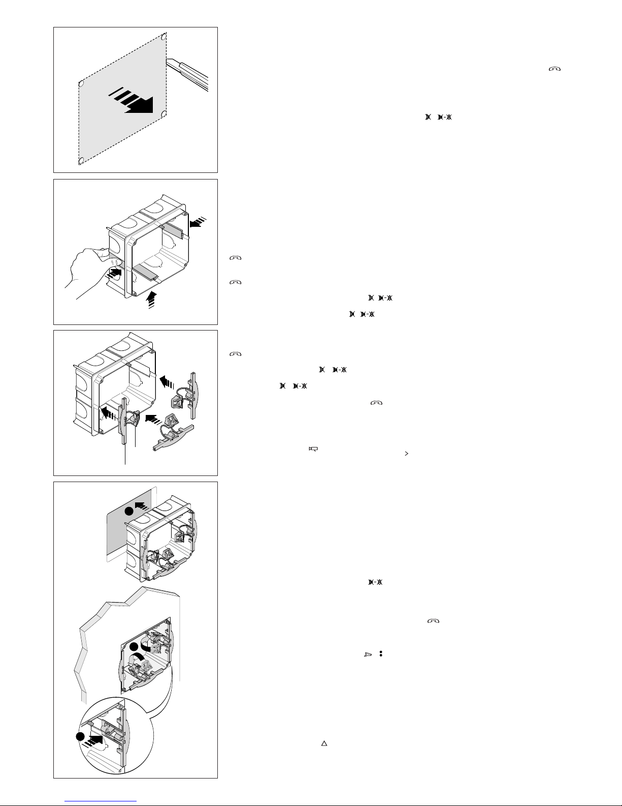
PHI embedding box
The embedding box can be installed in either masonry
or plasterboard walls at a height that is suitable for the
user (fig. 9-10-11).
Make sure the UP indication is facing the right way
indicated on the bottom of the embedding box.
- Dimensions: 130x114x53,5 mm.
Masonry wall installation
The embedding box should be installed flush with the
wall, and equipped with the provided protection (fig.
13) to be found in the packaging (fig. 12).
Installation on plasterboard walls
Press the box against the wall to get four reference
points where the holes with a 10 mm diameter will be
made (fig. 14).
Cut the plasterboar
d to obtain the hole where the box
will be inserted (fig. 15).
Remove the thr
ee tabs as shown in figur
e 16.
Insert the upper part A of the fastening clamps into
the box, leaving the lower part B free (fig. 17).
Place the embedding box into the hole and then apply
the lower part B (fig. 18).
Secur
e the box to the wall with the scr
ews provided
(fig. 19).
If the wall is more than 2 cm thick, the two parts of the
fastening clamps will need to be separated, positio
-
ning the lower part B as shown in figur
e 20.
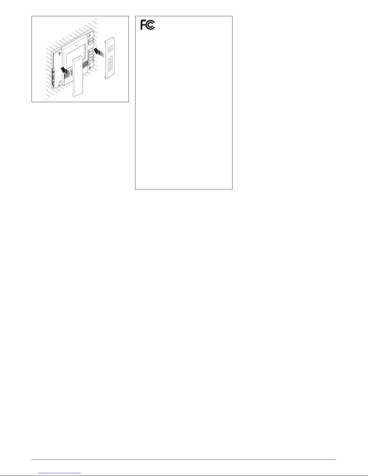
OPHERA and OPHERA/B video handset
Remove the two covers as shown in fig. 21. Wire the
connections.
Fasten the appliance to the embedding box, using the
screws provided (fig. 22).
Insert the covers as shown in fig. 23.
Replace the covers
The appliance is equipped with 3 sets of exchangeable covers in dif
fer
ent colours.
To replace, proceed as shown in fig. 21 and 23.
DISPOSAL
Do not litter the environment with packing material:
make sure it is disposed of according to the regulations
in force in the country where the product is used. When
the equipment r
eaches the end of its life cycle, take
measures to ensure it is not discarded in the environment. The equipment must be disposed of in compli
-
ance with the r
egulations in for
ce, r
ecycling its com
ponent parts wherever possible.
Components that qualify as r
ecyclable waste featur
e
the relevant symbol and the material’s abbre-viation.
11
12
50 cm
155 cm
160 cm
132 cm
188 cm
10
50 cm
145 cm
150 cm
122 cm
178 cm
2
1
3
13
1
10mm
2
Ø
14
E
INSTRUCCIONES PARA
LA UTILIZACIÓN Y INSTALACIÓN
LEVITON
LEVITON S de RL de CV
LAGO TANA 43 Col HUICHAPAN CP 11290
MEXICO DF Tel 5082 1040
LEA Y CONSERVE ESTE INSTRUCTIVO
4
A
B
3
2
CLIK!
1
16
17
18
Funciones básicas
-
Inhabilitación del timbre con señalación luminosa (el
videointercomunicador se activa con todas las funciones en cualquier caso), sólo en el modelo OPHERA.
- Señalización luminosa del estado de puerta abierta.
- Señalización de solicitud de comunicación por parte
d
e la centralita de conserjería.
- Entrada para llamada desde el rellano.
- Posibilidad de dirigir a un solo videointercomunicador la llamada de 3 botones de la placa externa.
- Llamadas distinguidas según su procedencia (placa
e
xterior, rellano, centralita de conserjería, intercomuni-
cador).
- Programación del tipo de nota de llamada desde la
placa exterior (4 melodías) y desde el rellano (4
melodías).
-
Programación del número de timbres de llamada
desde la placa exterior (la nota de llamada desde el
rellano no es programable).
- Desvío de llamada a otro derivado interno.
A falta de respuesta por parte del usuario llamado, trámite programación con MPP/300LR o PCS/300, es
posible desviar la llamada a otro derivado interno.
- Regulación, en 3 niveles, del volumen de la nota de
llamada.
Funcionamiento manos libres
T
ras la llamada desde placa exterior, pulsar el botón
para activar la comunicación, el LED se encende.
Para cerrar la comunicación, pulsar de nuevo el botón
, el LED se apaga.
S
i durante una conversación se desea interrumpir la
comunicación temporalmente, pulsar el botón (
en el modelo OPHERA/B), el LED parpadea.
Para retomar la comunicación, pulsar ( en el
modelo OPHERA/B), el LED se apaga.
Funcionamiento hablo-escucho
Tras la llamada desde placa exterior
, pulsar el botón
para activar la comunicación, el LED se encende.
Mantener pulsado el botón ( en el modelo
OPHERA/B) para hablar con la placa exterior.
Soltar el botón ( en el modelo OPHERA/B)
para escuchar, el LED se encende.
Para cerrar la comunicación, pulsar el botón , el
LED se apaga.
Selección de la placa exterior en equipos con
varias entradas
Con el equipo apagado, pulsar el botón de activación de la placa exterior
para encender el moni
tor, y volverlo a pulsar para seleccionar las placas
exteriores.
Alarma
La alarma se envía cada vez que un dispositivo remoto cualquiera, conectado a la entrada AL de la bor
nera M1, se activa.
Esta señalación tiene prioridad sobr
e todas las
demás.
El comando es administrado por la propia conserjería
(aparece el mensaje Alarma y el número del que
llama).
Intimidad (sólo en el modelo OPHERA/B)
Esta función sólo está activa con el videointercomunicador apagado.
Apr
etando el pulsador de Mute/Intimidad
el
usuario se aísla de todas las llamadas dirigidas a él, el
LED se encende.
Al conserje, si r
ealiza una llamada al derivado interno,
es indicado el estado Intimidad.
Para salir del estado de Intimidad se debe apretar de
nuevo el mismo pulsador
, el LED se apaga.
Llamada Conserje
Pulsando el botón de Llamada al conserje ( en
el modelo OPHERA, si se encuentra instalado) el
usuario realiza una llamada a la centralita de conserjería.
En caso de que el portero llame al usuario y el usuario no responda, el LED del derivado interno se
enciende si el porter
o deja un mensaje.
Cuando el usuario consiga ponerse en contacto con
el portero, se apagará el LED.
Pánico (sólo en el modelo OPHERA/B)
Pulsando el botón de Pánico
se envía a la centra
-
lita de conserjería el estado de pánico (apar
ece en
pantalla el mensaje 'Pánico' y el número del que
llama), el encendido del LED r
ojo confirma que el con
-
serje la ha recibido de forma correcta.
Este LED se apaga cuando el conserje llama al usuario.
E
sta señalación tiene prioridad sobre todas las
demás.
Calibrado de los niveles de audio
- Activar el derivado interno, pulsar el botón y
s
eleccionar la modalidad de funcionamiento hablo-
escucho.
- Ajustar los volúmenes en la placa exterior en funcionamiento hablo y escucho.
- Pasar al funcionamiento manos libres, pulsar el
b
otón ( en el modelo OPHERA/B) y comprobar que sea correcta la conmutación de un canal al
otro.
- Si hubiera dificultades para coger la línea en una de
las dos direcciones, aumentar ligeramente el volumen
e
n la dirección en que es difícil coger la línea y reducirlo ligeramente en la dirección opuesta.
En las instalaciones mixtas (derivados internos con
auricular y manos libres) se aconseja ajustar primero
los niveles de comunicación relativos a los derivados
m
anos libres.
Eventualmente ajustar en la placa exterior los volúmenes para conseguir la mejor solución.
Función del puente SW1
(Resistencia de cierre)
El aparato dispone de un puente SW1 (fig. 8) para la
impedancia de cierre de la línea señal. Eliminar el
p
uente si la línea prosigue hacia otros derivados inter-
nos de videointercomunicador.
Función del puente SW2
(Selección de fuente de alimentación)
El videointer
comunicador dispone de un puente
SW2
(
fig. 8) para seleccionar el tipo de alimentación (desde
BUS o desde alimentador separado).
Para alimentación desde BUS X1
(máx. 1 solo deri-
vado de vídeo portero activo)
, dirigir el puente SW2
a BUS (configuración por defecto).
Para alimentación separada, dirigir el puente
SW2 a
LOCAL (como derivado adjunto en llamada simultá-
nea o utilización en implantes X2).
VIDEOINTERCOMUNICADOR EN COLOR
MANOS LIBRES
INTERCOMUNICADOR OPHERA Y OPHERA/B
El accesorio de botones que se entrega permite transformar el videointercomunicador en un aparato intercomunicador.
Dispone de los siguientes comandos (fig. 4):
1÷4(5
÷8)
Pulsadores para la llamada
Pulsador de duplicación
(para llamadas 5÷8) (LED rojo)
Para aplicar el accesorio de botones, quitar la cubierta
izquier
da y desa
tor
n
illar los dos tornillos (fig. 5).
Montar el accesorio intercomunicador, atornillar los
dos tor
nillos y montar la cubierta (fig. 6-7).
El accesorio permite implementar las funciones básicas del videointercomunicador:
- Llamadas intercomunicadoras (máx. 8) con el selector VSE/301 o para activación de servicios auxiliares
trámite actuador
es.
- Transferencia de llamada en funcionamiento intercomunicación.
-
Aviso luminoso de instalación ocupada en led de
duplicación.
Durante una conversación interna, una eventual llamada desde la placa exterior es señalada al derivado
interno por una señal acústica breve repetida cada 5
s.
Presionando uno de los pulsadores de llamada y pul
sando es posible transferir la conversación a
otro derivado interno.
El derivado que ha recibido la llamada transferida
puede, a su vez, transferir de nuevo la llamada.
PROGRAMACIÓN BÁSICA
(sin utilización de pr
ogramador
es dedicados)
Para la programación de la llamada en las instalaciones
sistema 300 o X1 (X2) véase la documentación adjunta al alimentador XA/300LR y a la placa exterior X2.
Para la programación de los eventuales botones de
llamada 2 y 3 basta pulsar las teclas correspondientes después del primer pulsador de llamada, antes de
entrar en la pr
ogramación de los derivados internos.
NOTA. No salir de la programación del derivado
inter
no antes de haber asociado todas las llamadas
deseadas.
Para la programación de las llamadas intercomunicadoras véase las instrucciones que acompañan al
selector VSE/301.
15

5
2
1
A
B
>2 cm
19
20
OPHERA
OPHERA
21
22
PROGRAMACIÓN CON MPP/300LR
O
PCS/300
Es posible programar el aparato trámite MPP/300LR
utilizando el perfil dedicado para el derivado interno
XC/310 o mediante PCS/300 seleccionando el derivado correspondiente (OPHERA).
Programación de las melodías y del número de
timbres
Para entrar en la programación pulsar 5 veces el
botón dentro de 5 s.
U
na señal acústica breve confirma la entrada en la
programación (se entra automáticamente en la programación de la melodía de llamada desde la placa
exterior).
Para recorrer en secuencia el tipo de función, pulsar
e
l botón abrepuerta .
La entrada en cada función está identificada por un número correspondiente de señales acústicas breves:
A - 1 señal acústica: programación de la melodía
asociada con la llamada desde la placa exterior.
B
- 2 señales acústicas:programación de la melodía
asociada con la llamada desde el rellano.
C - 3 señales acústicas: programación del número
de timbres de llamada de la placa exterior.
A - Programación de la melodía asociada con la llamada desde la placa exterior
Se oye varias veces la melodía n. 1 de la llamada
d
esde la placa exterior, alternada con una señal acústica breve.
Para escuchar la melodía siguiente pulsar el botón
auxiliar 2 ( ) ( en el modelo OPHERA/B) durante
la pausa entre la señal acústica y la melodía.
R
epetir la operación hasta que se escucha la melodía
deseada.
Para memorizar la nueva configuración sin otras programaciones pulsar el botón , sino pulsar el
botón abrepuerta para entrar en la programación
siguiente.
B - Programación de la melodía asociada con la llamada desde el rellano
Se oye varias veces la melodía n. 1 de la llamada
desde el r
ellano, alternada con dos señales acústicas
breves.
Para escuchar la melodía siguiente pulsar el botón
auxiliar 2 ( ) ( en el modelo OPHERA/B) durante
la pausa entre la señal acústica y la melodía.
Repetir la operación hasta que se escucha la melodía
deseada.
Para memorizar la nueva configuración sin otras programaciones pulsar el botón , sino pulsar el
botón abr
epuerta para entrar en la programación
siguiente.
C - Programación del número de timbres de llamada
Se oyen 3 señales acústicas br
eves. Pulsar el botón
auxiliar 2 ( ) ( en el modelo OPHERA/B) tantas
veces cuantos son los timbr
es que se desea progra-
mar (de 1 a 6).
En instalaciones sistema 300, pr
evia personaliza
ción del alimentador XA/300LR, es posible aumentar el número de timbres hasta 51.
Al cabo de 3 s desde la última presión del botón se
oye la llamada seleccionada para el número de timbr
es seleccionado.
Si se desea memorizar las configuraciones sin ulteriores programaciones, pulsar el botón , sino pulsar
el botón
para acceder de nuevo a la programa-
ción de la melodía de llamada desde la placa exterior
.
NOT
A. Al salir de la programación son memorizadas
las últimas configuraciones seleccionadas para
cada tipo de programación.
Una configuración es considerada seleccionada
sólo si ha sido escuchada por lo menos una vez.
Para repetir el procedimiento de entrada en la programación, pulsar el botón
y esperar por lo
menos 5 s.
ATENCIÓN. En las instalaciones con XA/300LR se
r
ecomienda r
ecoger los códigos de identificación
ID (SN) de los derivados inter
nos, aplicados al exte
rior del meuble, y apuntarlos en las tablas adjuntas
a los aparatos XA/300LR, MPP/300LR y IPC/300LR.
Función de los bornes (fig. 8)
Bor
nera M1
alimentación local
de 12÷16 VAC ó 14÷18 VDC
B línea X1
+
e
ntrada llamada desde el rellano
–
AL entrada alarma (activo hacia masa)
C
aracterísticas técnicas
• Standard vídeo: NTSC.
• Display: LCD TFT de colores de 3,5”.
• Alimentación: local 12÷16 VAC o 14÷18 VDC, centralizada 14÷18 VDC.
•
Alimentación desde BUS: 15÷20 VDC.
• Consumo: 400 mA max (<1 mA en reposo).
• Número de derivados activos simultáneos desde
BUS X1: 1.
• Número máximo de derivados que se pueden
c
onectar al alimentador XA/300LR: 100.
• Número máximo de derivados que se pueden
conectar a una placa exterior X1: 64 (100 con
XAS/301).
• Línea de conexión X1: par no polarizado Z=100
Ω.
•
Temperatura de funcionamiento: entre 0 °C y +35
°C.
INSTALACIÓN
ATENCION. Se recomienda instalar el monitor
en un ambiente seco.
Caja de empotrar PHI
La caja puede instalarse tanto en un mur
o como en
una pared de yeso, a una altura adecuada para el
usuario (fig. 9-10-11) y respetando la indicación ALTO
que se muestra en el fondo de la caja empotrable.
- Dimensiones:130x114x53,5 mm.
Instalación sobre muro
La caja empotrable se encaja a ras de pared, equipada con la protección que se entrega con ella (fig. 13)
que se encuentra dentro del embalaje (fig. 12).
Instalación sobre pared de yeso
Apretar la caja contra la pared para marcar los cuatro
puntos de referencia para efectuar orificios de 10 mm
de diámetro (fig. 14).
Cortar el yeso para crear los orificios donde se introduce la caja (fig. 15).
Eliminar las 3 aletas que se indican en fig. 16.
Introducir en la caja la parte superior (A) de los bornes
de fijación, dejando libre la parte inferior (B) (fig. 17).
Introducir en el orificio la caja de empotrar y aplicar la
parte inferior B (fig. 18).
Fijar la caja a la pared por medio de los tornillos que
se entregan (fig. 19).
Si el espesor de la pared es mayor de 2 cm, es necesario separar las dos partes de los bornes de fijación
colocando la parte inferior (B) como se indica en fig.
20.
Videointercomunicador OPHERA y OPHERA/B
Quitar las dos cubiertas como se indica en fig. 21.
Realizar las conexiones. Fijar el aparato a la caja
empotrable usando los tor
nillos entr
egados (fig. 22).
Montar las cubiertas como se indica en fig. 23.
Sustitución de las cubiertas
El aparato se entrega con 3 juegos de cubiertas intercambiables de distinto colore.
Para la sustitución, actuar como se indica en fig. 21 y
23.
ELIMINACION
Comprobar que no se tire al medioambiente el material de embalaje, sino que sea eliminado conforme a
las normas vigentes en el país donde se utilice el pr
o
ducto.
Al final del ciclo de vida del aparato evítese que éste
sea tirado al medioambiente.
La eliminación del aparato debe efectuarse conforme
a las normas vigentes y privilegiando el reciclaje de
sus partes componentes.
En los componentes, para los cuales está prevista la
eliminación con reciclaje, se indican el símbolo y la
sigla del material.
6
OPH
ER
A
23
NOTA: este equipo ha sido ensaya-
do y declarado conforme a los límites establecidos para un dispositivo digital de
Clase B, de acuerdo con el Apartado 15 de
las Normas FCC. Estos límites han sido
d
iseñados para ofrecer una protección razonable contra interferencias perjudiciales en
una instalación residencial.
Este equipo genera, utiliza y puede emitir energía
de radiofrecuencia y, si no se instala y utiliza
conforme a las instrucciones, puede crear interferencias perjudiciales para las radiocomunicaciones. Sin embargo, no se garantiza que no se
produzcan interferencias en una instalación conc
reta.
Si este equipo crea interferencias perjudiciales
para la recepción de radio o televisión, lo cual
se puede comprobar apagando y encendiendo el equipo, se recomienda al usuario que
intente corregir la interferencia adoptando una
o varias de las siguientes medidas:
- Modifique la orientación o la posición de la
antena receptora.
- Aumente la distancia que separa el equipo
del receptor.
-
Conecte el equipo a un tomacorriente de un
circuito diferente de aquel al que está conectado el receptor.
- Solicite la asistencia de su distribuidor o de
un técnico de radio/TV cualificado.

7

8
 Loading...