

Page 1
1
Entry panel activation/selection (2)
Auxiliary 1 (3)
Auxiliary 2/Porter call (red LED)
Disabling the ring (red LED)
Adjusting the ring
Brightness
Saturation colour
(1) The door-lock release LED can only be used if the
appliance is activated and a specific connection has
been made for the entry panel series 300.
(
2
) The unit can only be switched on and consequently connected to the entry panel if the system
is not engaged with other calls.
(
3
) This control can only be used if the unit is on.
By using actuators VLS/300 or customizing control
unit XA/300LR by means of programmer
MPP/300LR or PCS/300, you can have the control
enabled at all times.
OPHERA/B HANDS-FREE COLOUR
VIDEO HANDSET
Features similar to video handset OPHERA.
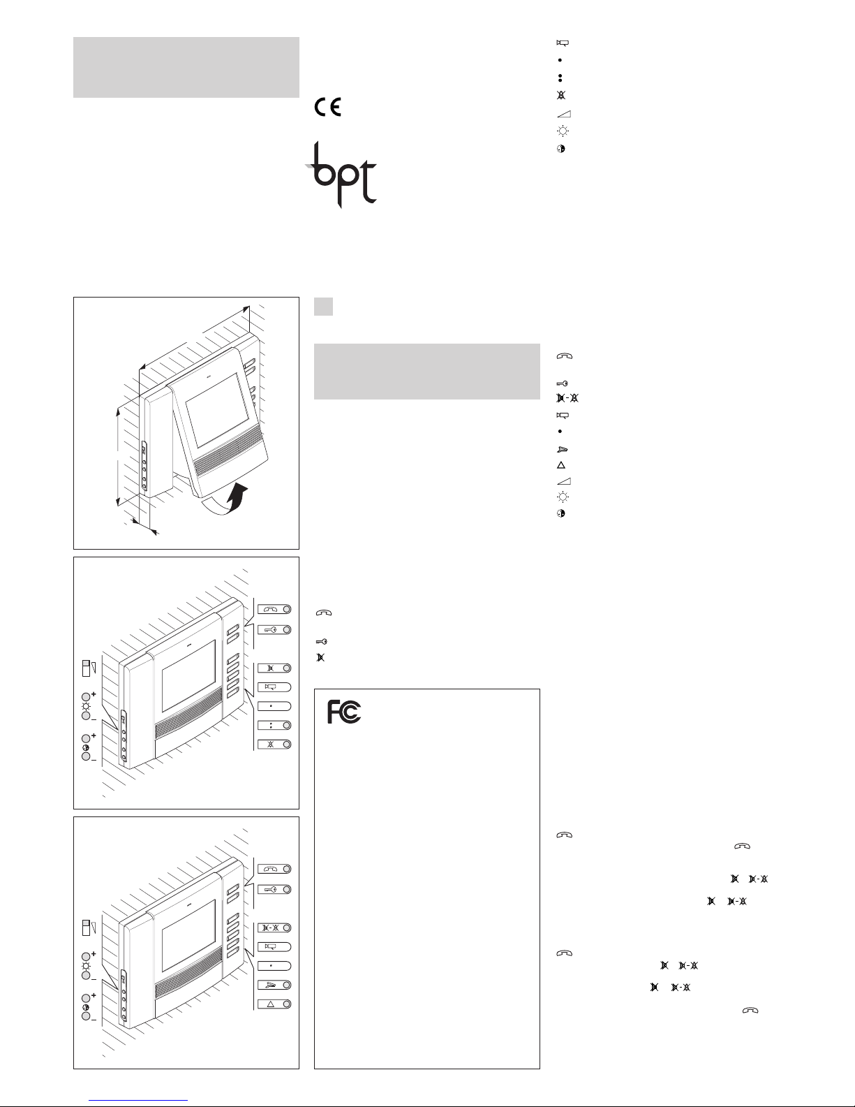
It features the following controls and adjusters (fig. 3):
Activating/De-activating communication
(red LED)
Door lock release (green LED) (
1
)
Mute/Privacy (red LED)
Entry panel activation/selection (
2
)
Auxiliary 1 (
3
)
Porter call (red LED)
Panic (red LED)
Adjusting the ring
Brightness
Saturation colour
Standard functions
- Disabling the ring with light signal (the video handset
is still activated with all its functions), in the OPHERA
model only.
- Door open warning light.
- Warning that porter switchboard is trying to get in
touch.
- Doorbell input.
- Possibility to route the call from 3 externally located
buttons to one video intercom.
- Distinctive ringing depending on where the call is
made from (entry panel, doorbell, porter switchboard,
intercom unit).
- Call note type can be programmed to distinguish
between a call made from the entry panel (4 melodies)
and the doorbell (4 melodies).
- Number of rings announcing the call can be programmed from the entry panel (the doorbell note is
not programmable).
- Call can be rerouted to another receiver.
If the user called does not answer, the call can be
rerouted to another receiver by programming with
MPP/300LR or PCS/300.
- Adjusting the volume of the ring to 3 levels.
Hands-free operation
When a call is made from the entry panel, press the
button to initiate communication, the LED light.
To end communication, press the button again,
the LED goes off.
If you wish to interrupt a communication temporarily
during a conversation, press the button ( in
the OPHERA/B model), the LED flashes.
To restore communication press ( in the
OPHERA/B model), the LED goes off.
Talk-listen operation
When a call is made from the entry panel, press the
button to initiate communication, the LED light.
Press down the button ( in the OPHERA/B
model) to speak with the entry panel.
Release the button ( in the OPHERA/B
model) to listen,the LED light.
To end communication, press the button , the
LED goes off.
Entry panel selection in installations with a number of entry panels
With the system off, turn on the monitor by pressing
24800401 - 12-03-10
OPHERAKIT/..US
WARNINGS FOR THE USER
- In the case of breakdown or modification of the
apparatus of the system (such as power supplier...) please contact a specialized maintenance service.
WARNING
Cleaning of the screen and unit cabinet should only be
done with a soft cloth.
OPHERA HANDS-FREE COLOUR
VIDEO HANDSET
OPHERA hands-free colour video handset can be
used with video entry systems series 300, X2, X1 and
XUP.
It must installed in a PHI dedicated rectangular
embedding box.
This appliance has a moveable part that can be tilted
outwards by 16° (fig. 1).
The video handset is equipped for the insertion of a
provided button accessory, which allows the intercommunication function to be added.
It features the following controls and adjusters (fig. 2):
Activating/De-activating communication
(red LED)
Door lock release (green LED) (
1
)
Mute (red LED)
THESE INSTRUCTIONS SHOULD BE ATTACHED
TO THE APPARATUS
ESTAS INSTRUCCIONES SE DEBEN ANEXAR
AL APARATO
BPT S.p.A.
Via Cornia, 1
33079 Sesto al Reghena-PN-Italy
[email protected] – www.bpt.it
O
P
H
E
R
A
124,8
158,8
17,5
1
O
P
H
E
R
A
2
O
P
H
E
R
A
3
EN
INSTRUCTIONS FOR USE
AND INSTALLATION
NOTE: This equipment has been
tested and found to comply with
the limits for a Class B digital
device, pursuant to Part 15 of the FCC
Rules. These limits are designed to provide
reasonable protection against harmful
interference in a residential installation.
This equipment generates, uses and can
radiate radio frequency energy and, if not
installed and used in accordance with the
instructions, may cause harmful interference to radio communications. However,
there is no guarantee that interference will
not occur in a particular installation.
If this equipment does cause harmful interference to radio or television reception,
which can be determined by turning the
equipment off and on, the user is encouraged to try to correct the interference by one
or more of the following measures:
- Reorient or relocate the receiving antenna.
- Increase the separation between the
equipment and receiver.
- Connect the equipment into an outlet on
a circuit different from that to which the
receiver is connected.
- Consult the dealer or an experienced
radio/TV technician for help.
Page 2
- Intercom calls (max. 8) with VSE/301 selector or for
activating auxiliary services with actuators.
- Call transfer in intercom mode.
- Light signal with doubling LED to indicate system
busy.
If there is a call from the entry panel during a conversation between intercom sets, a short audible signal
repeated every 5 s advises the receiver’s user of the
call. By pressing one of the call buttons and pressing
, the conversation can be transferred to another
receiver.
The receiver receiving the transferred call can, in turn,
transfer the call.
STANDARD PROGRAMMING
(without using relevant programmers)
To programme the call in system 300 or X1 (X2) installations, see the literature enclosed with the XA/300LR
control unit and X2 entry panel.
To program call buttons 2 and 3, where necessary,
simply press the corresponding keys following the first
call button once you have entered receiver programming mode.
NOTE. Do not exit receiver programming mode until
you have associated all the desired calls.
To programme intercom calls, see the instructions
provided with the VSE/301 selector.
PROGRAMMING WITH MPP/300LR
OR PCS/300
The unit can be programmed through the
MPP/300LR unit using the dedicated profile for the
XC/310 receiver, or by means of PCS/300 by selecting the corresponding receiver (OPHERA).
Programming melodies and number of rings
To enter programming mode, press the button 5
times, within 5 s.
A short audible signal sounds to confirm you have
entered programming mode (you automatically enter
the entry panel call melody programming procedure).
Press the door lock release button to run through
the different modes in sequence.
A number of short audible signals sound to indicate
that you have entered the corresponding mode:
A -1 audible signal: programming of melody associated with the call from the entry panel.
B - 2 audible signals: programming of melody associated with doorbell.
C -3 audible signals: programming of number of
rings announcing a call from the entry panel.
A - Programming of melody associated with the call
from the entry panel
The first entry panel call melody is played repeatedly,
alternated with a short audible signal.
To listen to the next melody, press the auxiliary button
2 ( ) ( in the OPHERA/B model) during the pause
between the audible signal and melody.
Repeat the operation until you hear the melody you
want.
To save the new setting without programming
anything else, press the button ; or press the
door lock release button to access the next programming procedure.
B - Programming of melody associated with doorbell
The first doorbell melody is played repeatedly, alternated with two short audible signals.
To listen to the next melody, press the auxiliary button
2 ( ) ( in the OPHERA/B model) during the pause
between the audible signal and melody.
Repeat the operation until you hear the melody you
want.
To save the new setting without programming
anything else, press the button ; or press the
door lock release button to access the next programming procedure.
C - Programming of number of rings announcing a
call
Three short audible signals sound.
Decide how many rings you want and press the auxiliary button 2 ( ) ( in the OPHERA/B model) the
corresponding number of times (in the range 1 to 6).
In system 300 installations, you can increase the
number of rings to a maximum of 51 by customizing
control unit XA/300LR.
3 s after the button was last pressed, you will hear the
call selected for the chosen number of rings.
If you want to save settings without programming
anything else, press the button ; or press the
the entry panel activation button . Press again to
switch between entry panels.
Alarm
The alarm is sent each time any remote device connected to the AL input of the M1 terminal block is activated.
This warning takes priority over all the others.
The command is handled through the actual porter
switchboard (the message Alarm and the user's number come up on the display).
Privacy (in the OPHERA/B model only)
This function is active only with the video handset station off.
The user can press the Mute/Privacy button to isolate the receiver from all calls sent to it, the LED light.
When making a call to the receiver, the porter receives
the Privacy status warning.
Press the same button again to exit Privacy status,
the LED goes off.
Porter call
By pressing the Porter call button ( in the
OPHERA model where installed) a call is made by the
user to the porter switchboard.
Should the porter call the user and the user fail to
answer, the LED on the receiver comes on if the porter leaves a message.
Once the user manages to speak with the porter, the
LED goes off.
Panic (in the OPHERA/B model only)
By pressing the Panic button the panic status is
sent to the porter switchboard (the message Panic
and the user's number come up on the display).
The red LED comes on to confirm receipt by the porter. This LED goes off when the porter calls the user.
This warning takes priority over all the others.
Calibrating the audio levels
- Activate the receivers and select the talk-listen
operating mode.
- Adjust the volumes on the entry panel in the talklisten mode.
- Go to the hands-free mode ( in the OPHERA/B model) and check the regularity of switching
from one channel to another.
- If there is difficulty in getting the line in one of the two
directions, increase the volume slightly in the direction
where you have difficulty and reduce it in the other
direction.
In combined systems (receivers and hands-free) we
recommend you first adjust the communication levels
for the hands-free system.
If necessary, adjust the volumes on the entry panel to
achieve a better compromise.
Function of jumper SW1
(Resistive load termination)
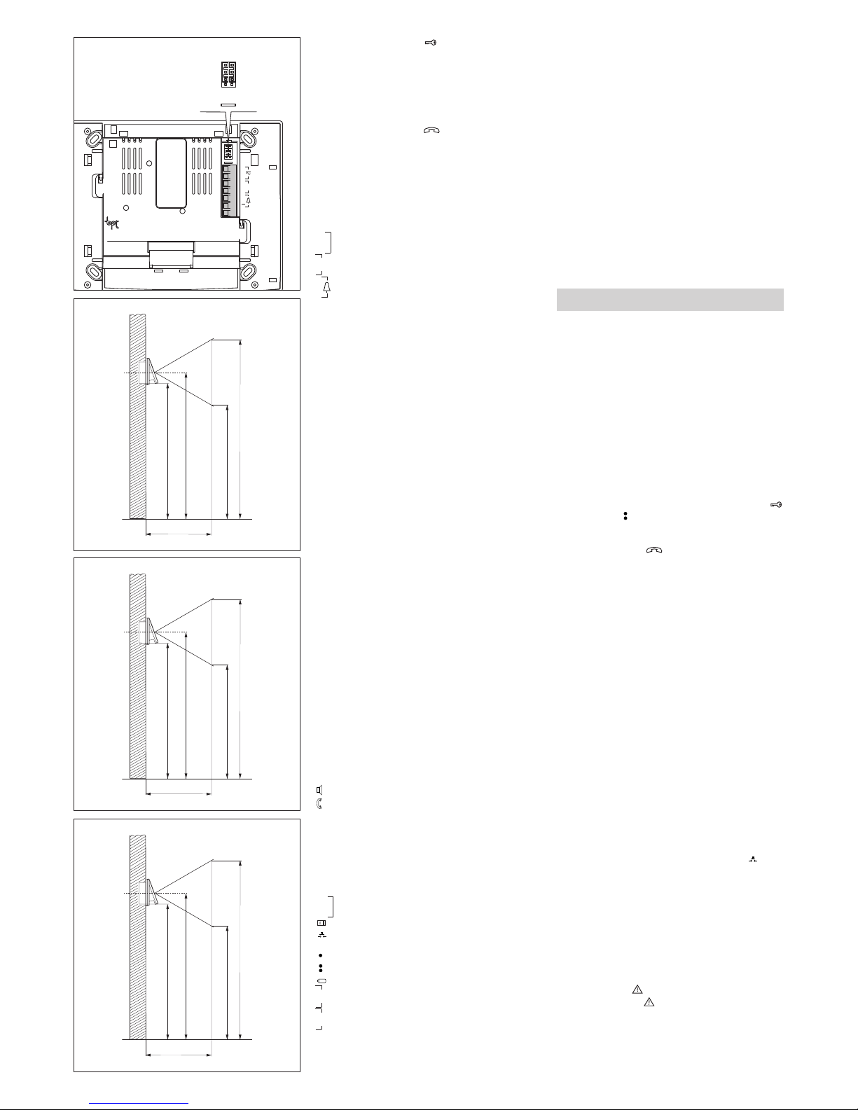
The unit features a jumper SW1 (fig. 8) for the impedance terminating the signal line. Remove the jumper if
the line continues towards other video handsets.
Function of jumper SW2
(Selects power source)
The video handset has a jumper SW2 (fig. 8) for selecting the type of power supply (from BUS or a separate power supply unit).
For power supply from X1 BUS (max. 1 video hand-
set active only), position jumper SW2 on BUS
(default setting).
For separate power supply, position jumper SW2 on
LOCAL (as additional receiver for a simultaneous call
or use in X2 installations).
OPHERA AND OPHERA/B HANDS-FREE
INTERCOMMUNICATING COLOUR
VIDEO HANDSET
The button accessory provided lets the video handset
change to an intercommunicating appliance.
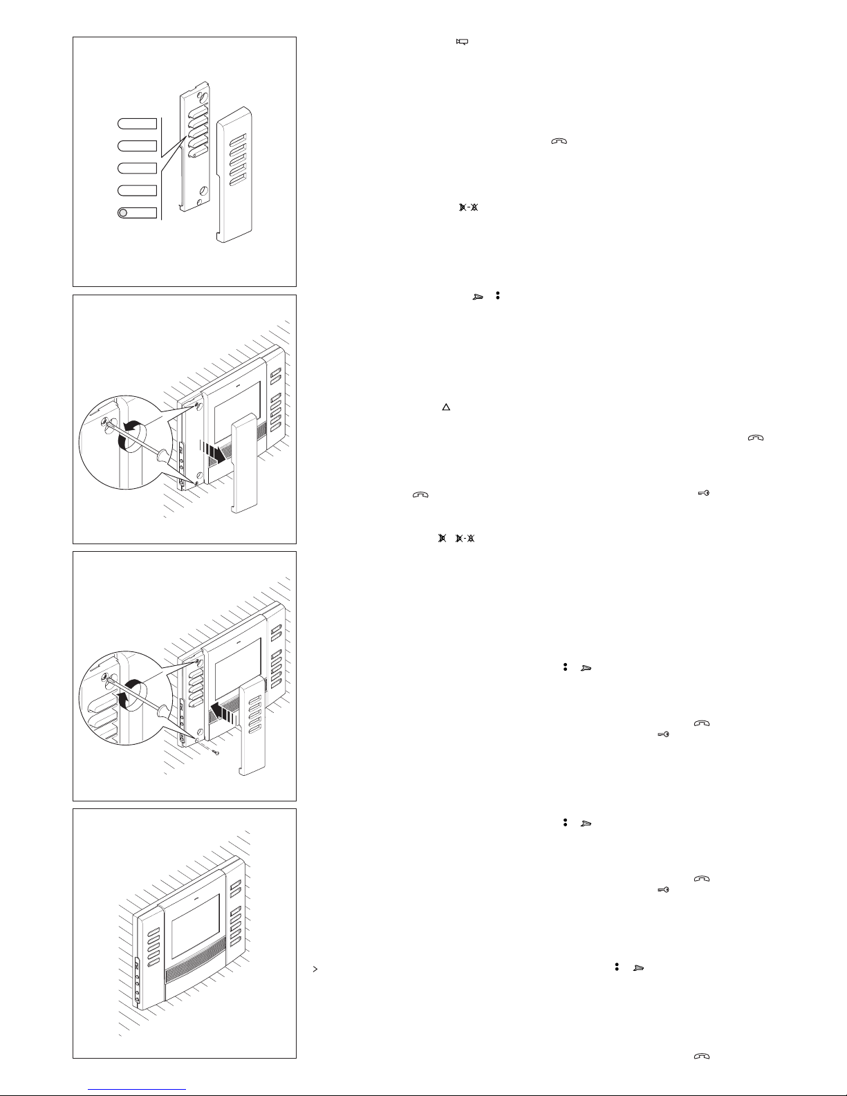
It features the following controls (fig. 4):
1÷4(5÷8) Call buttons
Doubling button (for calls 5÷8)
(red LED)
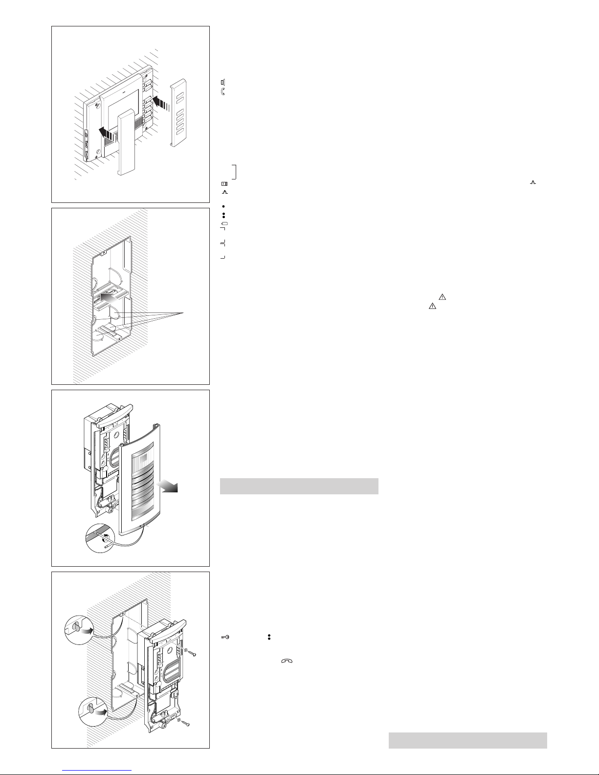
To apply the button accessory, remove the left cover
and unscrew the two screws (fig. 5).
Insert the intercommunicating accessory, tighten the
two screws and insert the cover (fig. 6-7).
This accessory allows the basic functions for the
video handset to be used:
2
1 - 5
2 - 6
3 - 7
4 - 8
>
4
OPHERA
2
5
OPHERA
1 - 5
2 - 6
3 - 7
6
O
PHERA
7
Page 3
3
door lock release button to enter the entry panel
call melody programming procedure again.
NOTE. When you exit programming mode, the last
settings selected for each programming procedure
are saved. For a setting to be taken as selected, you
must have heard it at least once.
To repeat the procedure to enter programming
mode, press the button and wait at least 5 s.
WARNING. In installations with XA/300LR we
recommend you gather up the receiver’s ID (SN)
codes, applied on the outside of the housing, and
enter them in the tables that come with the
XA/300LR, MPP/300LR and IPC/300LR.
Function of each terminal (fig. 8)
Terminal block M1
L power supply local
N from 12÷16 V AC or 14÷18 V DC
B X1 line
+
doorbell input
–
AL alarm input (active to earth)
Technical features
• Video signal system: NTSC.
• Display: 3,5” colour LCD TFT.
• Supply voltage: local 12 to 16 VAC or 14 to 18
VDC, centralized 14 to 18 VDC.
• Power supply from BUS: 15÷20 VDC.
• Current demand: 220 mA max. (<1 mA quiescent).
• Number of receivers activated at the same time by
X1 BUS: 1.
• Maximum number of receivers that can be connected to control unit XA/300LR: 100.
• Maximum number of receivers that can be connected
to an X1 entry panel: 64 (100 with XAS/301).
• X1 connection line: non polarized twisted pair
Z=100 Ω.
• Working temperature range: 0 °C to +35 °C.
VIDEO ENTRY PANEL HEV/301
Single-button video entry panel for managing the
whole installation.
Teamed with button plates HEP/306-HEP/312D,
installations with up to 64 users can be set up.
For connections to user extensions the entry panel
uses BPT X1 TECHNOLOGY bus connection, enabling all signals involved in installation to be sent along
a telephone-type single twisted pair line.
An additional three video-entry or audio-only entry
panels can be added to the first in series without the
need for other equipment (selectors, distributors).
The entry panel comes ready to house the KHSO
luminous system busy warning kit and 1 KHPS (or 1
KHPD) call kit.
The entry panel comes complete with:
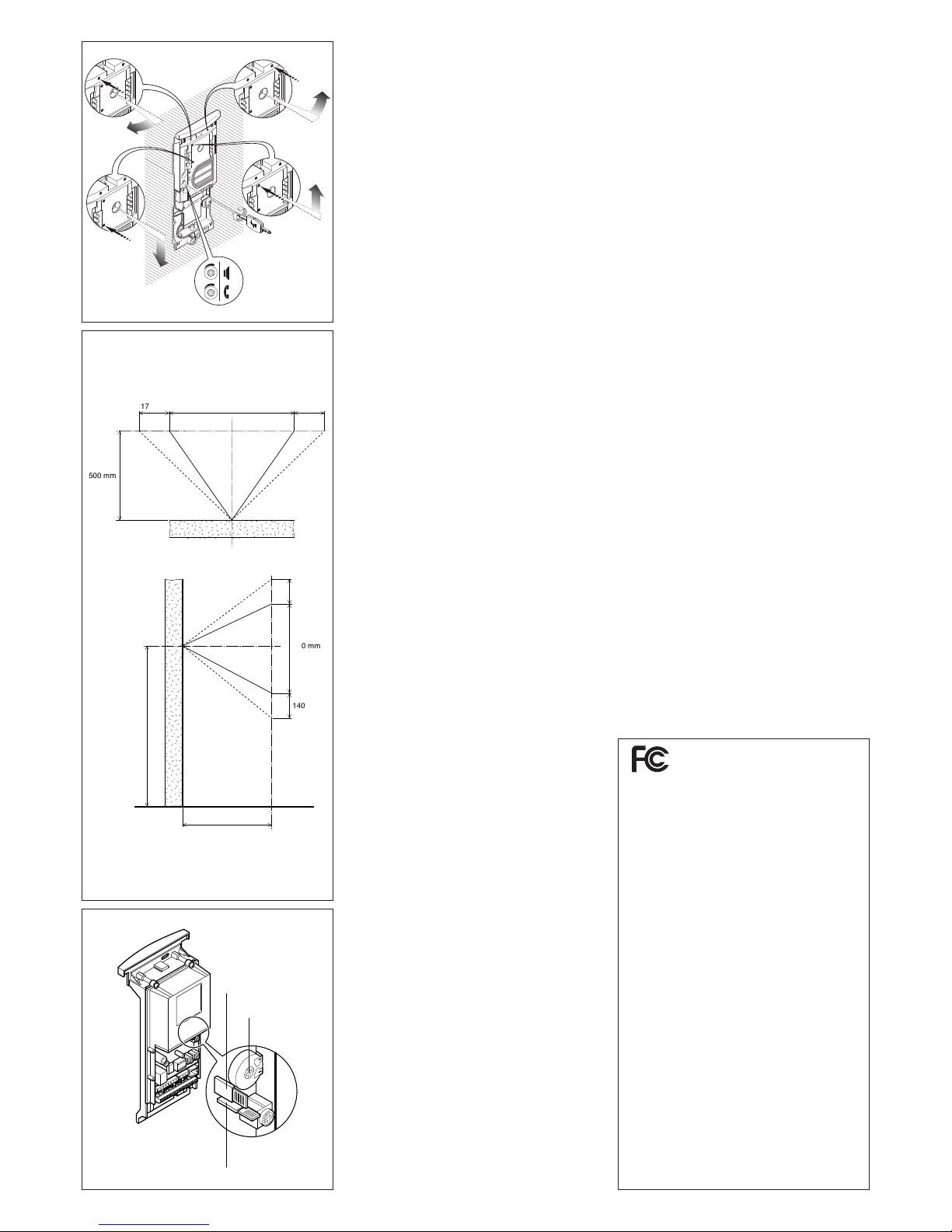
- CCD camera with ±11° manual angle adjustment
both horizontally and vertically (fig. 26), with fixedfocus lens (see fig. 27 for dimensions of the target
area);
- phonic unit;
- infrared LED for lighting the target area;
- three potentiometers for the following functions (fig.
26-28):
volume control at entry panel;
volume control at receiver;
P1 timed (in the range 1 to 15 s) solenoid door-lock
release.
The entry panel comes with system busy and doorlock release buzzer.
The wires supplied make it simple to connect the
entry panel’s various component units.
Function of each terminal
L 14-18V DC
N power supply
solenoid lock output
door-lock release button
– earth for solenoid lock
auxiliary command 1 output
auxiliary command 2 output
entry panel enabling output
B IN
bus input from
other entry panels
B OUT
bus output towards receivers or other entry
panels
Connector functions
5-pin CN1 connector: used for connection to entry
panel HEP/306 or HEP/312D.
3-pin CN3 connector: used for connection to buttons
KHPS or KHPD.
1-red: to button n° 2.
2-orange: to button n° 3.
3-yellow: to button n° 4.
WARNING. In installations with a number of entry
panels, call buttons must be arranged in the same
order on each.
Connector CN4: comes ready connected.
1-black: to button no. 1.
2-brown: to button no. 1.
3-green: to LEDs lighting the buttons.
4-yellow: to LEDs lighting the buttons.
2-pin CN5 connector: used for connection to KHSO
luminous warning kit.
Function of jumpers SW1 and SW2 (fig. 28)
SW1: automatic programming of number of entry
panels (default setting 1).
SW2: programming of receivers.
WARNING. Wires belonging to cables that are
not used must be insulated.
Programming of number of entry panels (only
required where there is more than one entry panel)
1 - Start with the last entry panel connected in series
to the bus (usually the one with terminals BINnot
connected).
2 - Remove jumper SW1.
3 - Wait for the note confirming the operation
(approximately 3÷15 s).
The number of confirmation signals also indicates the
number of present and programmed entry panels (1
signal for the main entry panel and 1 signal for each
secondary entry panel).
4 - Refit jumper SW1.
Programming receivers
1 - Remove jumper SW2 from any entry panel.
2 - Simultaneously press the door-lock release
and auxiliary 2 buttons for at least 1 s (the video, if
present, will activate, to confirm that hte operation has
occurred).
3 - Briefly press the button to establish contact
with the entry panel.
4 - On the entry panel, press the call button the receiver is to be associated with.
5 - Repeat the operation from point 2 on for all remaining receivers.
6 - Refit jumper SW2 to exit programming.
WARNING. The programming procedure for the
VSE/301 selector, where fitted, must only be
performed once you have programmed which
calls from the entry panels are to be associated
with which receivers.
In installations with XA/300LR we recommend
you gather up the receiver’s ID (SN) codes,
applied on the outside of the housing, and enter
them in the tables that come with the XA/300LR,
MPP/300LR and IPC/300LR.
NOTE. Once the power supplier has been programmed using a PCS/300 or MPP/300LR unit, it
will no longer be possible to gain access to the
entry panel standard programming.
To restore default conditions, please refer to the
related chapter.
Return to default conditions from entry panel
1 - Remove the SW1 jumper.
2 - Close the earthed door open contact (–, ).
A sound signal confirms that the operation has occurred.
3 - Replace the SW1 jumper
COLOUR VIDEO ENTRY PANEL HEVC/301
Video entry panel complete with colour CCD camera
and white-light LED for lighting the target area.
Its features and functions are similar to those of entry
panel HEV/301.
Technical features
• Power supply: 14÷18 V DC.
• Current demand:
- on stand-by with 14V DC max. 230 mA;
- operating with 14V DC max. 380 mA;
- with door-lock release activated, add 500 mA;
- for each HEP/306-HEP/312D, add 35 mA;
- for each XDV/300A connected, add 40 mA;
- for 64 receivers, add 64 mA.
SW2
SW1
BUS
LOCAL
B
AL
+
M1
8
9
50 cm
135 cm
140 cm
112 cm
168 cm
10
50 cm
145 cm
150 cm
122 cm
178 cm
11
50 cm
155 cm
160 cm
132 cm
188 cm
Page 4
4
• Secrecy of speech/privacy of video signal.
• Door-lock release command: pulse-type for solenoid lock at 12 V 1 A.
• Timed solenoid door-lock release: adjustable in the
range 1 to 15 s.
• Installation activation time: 60 s.
• Call duration time: 30 s.
• Bus output: power supply at 15 V DC for booster
and receivers video driver balanced type (Z = 100
Ω).
• Aux 1 command output: 3.5 V DC at 1 mA (available only with entry panel enabled, activation time
same as timed solenoid door-lock release).
• Aux 2 command output: 3.5 V DC at 1 mA (always
available in all entry panels, activation time same as
timed solenoid door-lock release).
• Entry panel activation output: 3.5 V DC at 1 mA
(enabled for entire duration of conversation).
• Working temperature range: -15 °C to +50 °C.
Camera technical features of HEV/301 entry panel
• Video signal system: NTSC.
• Sensor: 1/4” CCD.
• Horizontal frequency: 15,625 Hz (15,750 Hz EIA).
• Vertical frequency: 50 Hz (60 Hz EIA).
• Video output: 1 Vpp composite to 75 Ω.
• Resolution: 380 lines.
• Minimum illumination: 5 lx.
• S/N ratio: 45 dB.
• Iris control: automatic electronic in the range 1/50 s
1/100,000 s.
• Lens: fixed-focus f 3.7 F 4.5.
Camera technical features of HEVC/301 entry panel
• Video signal system: NTSC.
• Sensor: 1/4” CCD.
• Horizontal frequency: 15,625 Hz.
• Vertical frequency: 50 Hz.
• Video output: 1 Vpp composite to 75 Ω.
• Resolution: 330 lines.
• Minimum illumination: 50 lx.
• S/N ratio: 46 dB.
• Iris control: automatic electronic.
• Lens: fixed-focus f 3.7 F 5 (pin-hole).
INSTALLATION
WARNING. It is recommended to install the
monitor in a dry place.
PHI embedding box
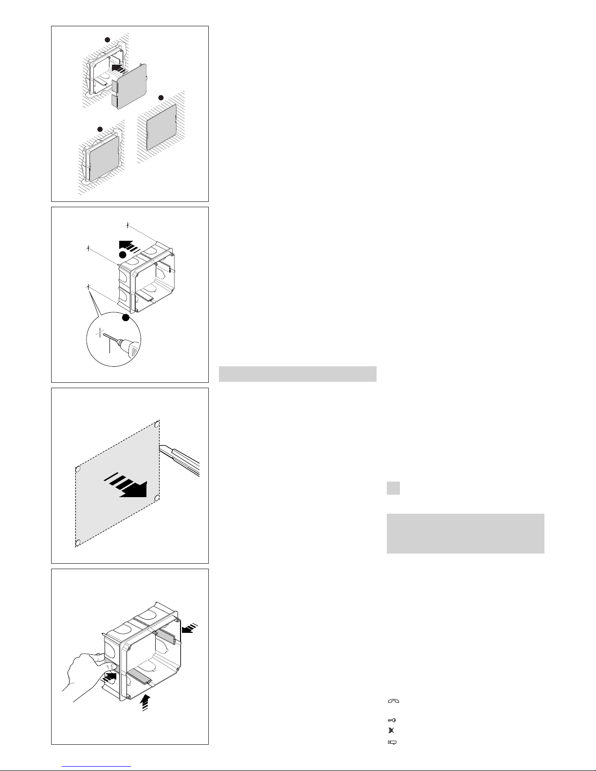
The embedding box can be installed in either masonry
or plasterboard walls at a height that is suitable for the
user (fig. 9-10-11).
Make sure the UP indication is facing the right way
indicated on the bottom of the embedding box.
- Dimensions: 130x114x53,5 mm.
Masonry wall installation
The embedding box should be installed flush with the
wall, and equipped with the provided protection (fig.
12).
Installation on plasterboard walls
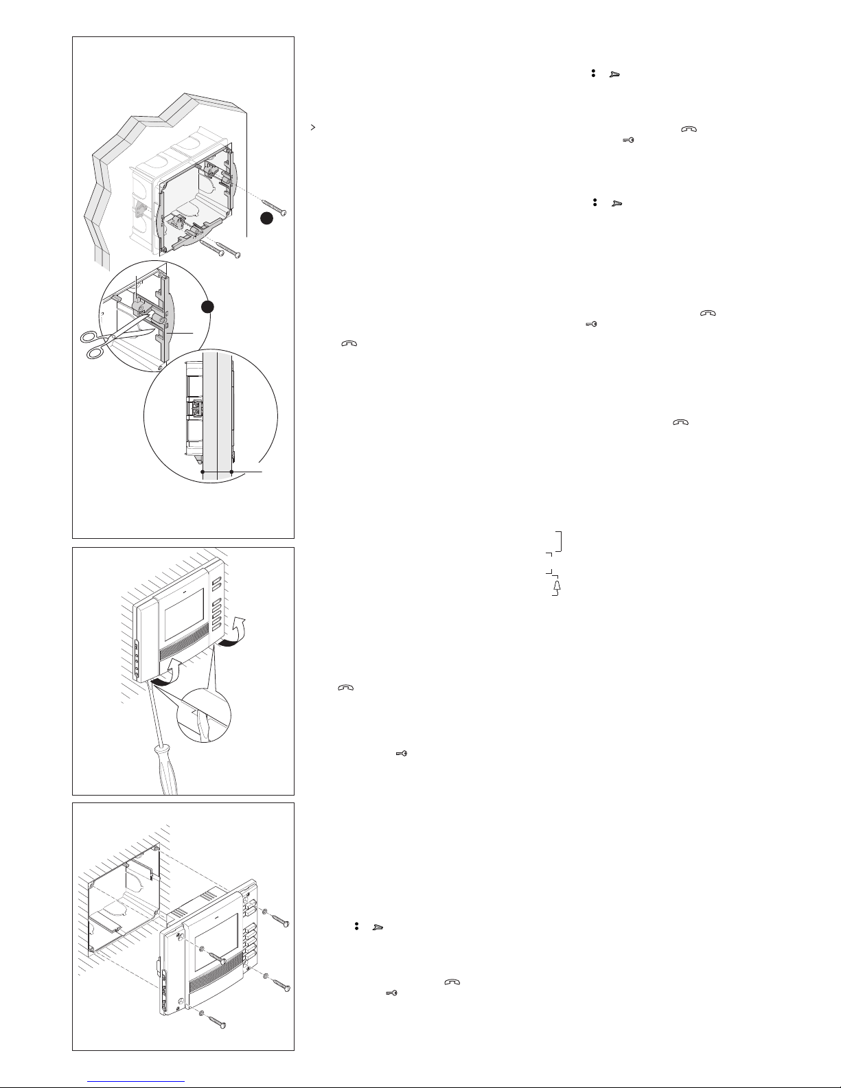
Press the box against the wall to get four reference
points where the holes with a 10 mm diameter will be
made (fig. 13).
Cut the plasterboard to obtain the hole where the box
will be inserted (fig. 14).
Remove the three tabs as shown in figure 15.
Insert the upper part A of the fastening clamps into
the box, leaving the lower part B free (fig. 16).
Place the embedding box into the hole and then apply
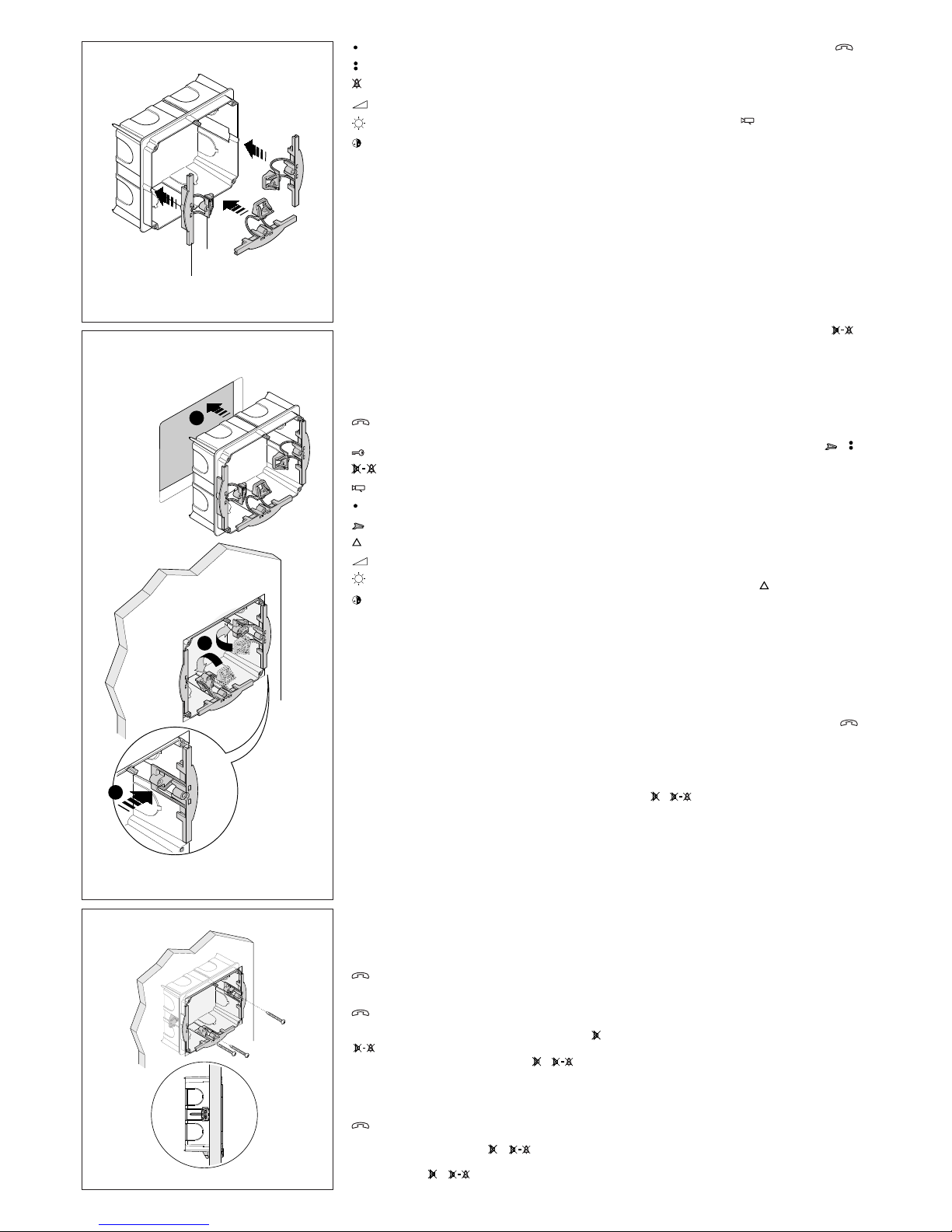
the lower part B (fig. 17).
Secure the box to the wall with the screws provided
(fig. 18).
If the wall is more than 2 cm thick, the two parts of the
fastening clamps will need to be separated, positioning the lower part B as shown in figure 19.
OPHERA and OPHERA/B video handset
Remove the two covers as shown in fig. 20. Wire the
connections.Fasten the appliance to the embedding
box, using the screws provided (fig. 21).
Insert the covers as shown in fig. 22.
Replace the covers
The appliance is equipped with 3 sets of exchangeable covers in different colours.To replace, proceed as
shown in fig. 20 and 22.
Video entry panel HEV/301-HEVC/301
The embedding box must be fitted flush with the wall
and at an height that ensure optimal camera operation. Fit the spacer into embedding boxes to avoid
deformation (fig. 23).
It is possible to use the screwdriver obtained from the
spacer to adjust the microphone and speaker volume
(fig. 26).
WARNING. Connecting cables must be fed through
one of the knockout cable entry points, located at
the bottom of the embedding box (A in fig. 23).
Using the Allenkey s 2.5 supplied, unscrew the lock
screw and remove the front plate from the chassis (fig.
24).
In order to fit additional buttons, follow the instructions supplied with each.
Remove the two plugs protecting the threaded holes
in the embedding box and secure the chassis using
the two screws supplied (fig. 25).
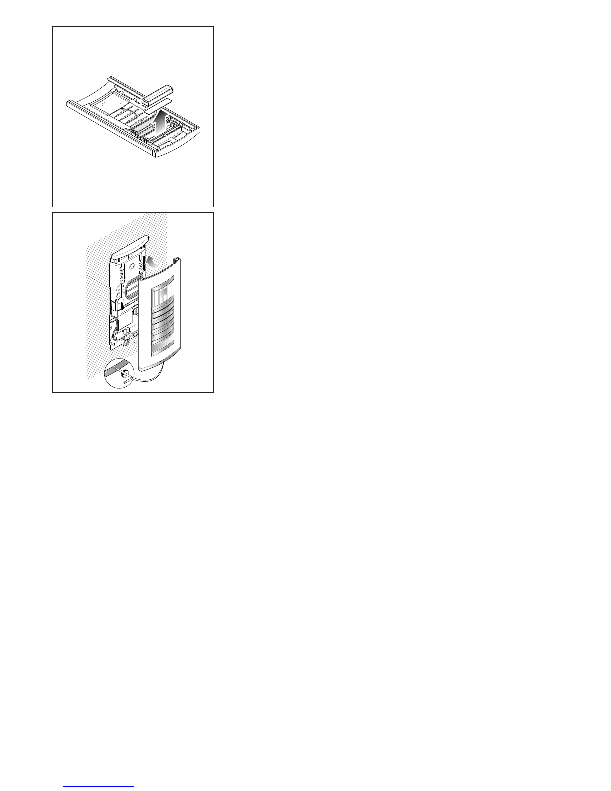
Perform the wiring. The name card can be removed
and filled in with the relevant information by removing
the card clip followed by the actual card itself (fig. 29).
NOTE. Personalized name cards can be used up to a
maximum of 2 mm thick.
In order to fit the front plate, first insert the upper part
in the top moulding and then, using a Allenkey s 2.5,
tighten the lock screw (fig. 30).
DISPOSAL
Do not litter the environment with packing material:
make sure it is disposed of according to the regulations in force in the country where the product is
used.
When the equipment reaches the end of its life cycle,
take measures to ensure it is not discarded in the
environment.
The equipment must be disposed of in compliance
with the regulations in force, recycling its component
parts wherever possible.
Components that qualify as recyclable waste feature
the relevant symbol and the material’s abbreviation.
2
1
3
12
1
10mm
2
Ø
13
14
15
E
INSTRUCCIONES PARA
LA UTILIZACIÓN Y INSTALACIÓN
ADVERTENCIAS PARA EL USUARIO
- En caso de avería o necesidad de modificación o intervención sobre los aparatos de la
instalación (alimentador, etc.) dirigirse al personal especializado.
ATENCIÓN.
La limpieza de la pantalla y del mueble del aparato
debe efectuarse usando sólo un paño suave.
VIDEOPORTERO EN COLOR
MANOS LIBRES OPHERA
Videoportero en color con manos libres OPHERA,
para utilizar en instalaciones de videoporteros de la
serie 300, X2, X1 y XUP.
Debe instalarse en una específica caja empotrable
rectangular PHI. En el aparato hay una parte móvil
que se puede inclinar 16° hacia el exterior (fig. 1).
El videoportero está predispuesto para introducir un
accesorio de botones que se entrega junto con él, y
que permite añadir la función intercomunicadora.
Dispone de los siguientes mandos y regulaciones (fig.
2):
Activación/Desactivación comunicación
(LED rojo)
Abrepuerta (LED verde) (
1
)
Mute (LED rojo)
Habilitación y selección placa exterior (
2
)
LEVITON
LEVITON S de RL de CV
LAGO TANA 43 Col HUICHAPAN CP 11290
MEXICO DF Tel 5082 1040
LEA Y CONSERVE ESTE
INSTRUCTIVO
Page 5
5
A
B
16
3
2
CLIK!
1
17
18
Auxiliar 1 (3)
Auxiliar 2/Llamada conserje (LED rojo)
Inhabilitación del timbre (LED rojo)
Regulación del timbre
Luminosidad
Saturación color
(
1
) El LED del abrepuerta sólo se puede usar si el
aparato se encuentra activo y se ha realizado una
conexión específica en la placa exterior serie 300.
(
2
) El encendido del aparato y la consiguiente
conexión con la placa exterior se pueden realizar
solo si el equipo no está ocupado por otras comunicaciones.
(
3
) Es posible utilizar este comando sólo si el aparato está activo.
Previa utilización de actuadores VLS/300 o personalización del alimentador XA/300LR mediante programador MPP/300LR o PCS/300, el comando está
siempre disponible.
VIDEOPORTERO EN COLOR
MANOS LIBRES OPHERA/B
Con características parecidas a los videoportero
OPHERA.
Dispone de los siguientes mandos y regulaciones (fig.
3):
Activación/Desactivación comunicación
(LED rojo)
Abrepuerta (LED verde) (
1
)
Mute/Intimidad (LED rojo)
Habilitación y selección placa exterior (
2
)
Auxiliar 1 (
3
)
Llamada conserje (LED rojo)
Pánico (LED rojo)
Regulación del timbre
Luminosidad
Saturación color
Funciones básicas
- Inhabilitación del timbre con señalación luminosa (el
videoportero se activa con todas las funciones en
cualquier caso), sólo en el modelo OPHERA.
- Señalización luminosa del estado de puerta abierta.
- Señalización de solicitud de comunicación por parte
de la centralita de conserjería.
- Entrada para llamada desde el rellano.
- Posibilidad de dirigir a un solo videoportero la llamada de 3 botones de la placa externa.
- Llamadas distinguidas según su procedencia (placa
exterior, rellano, centralita de conserjería, intercomunicador).
- Programación del tipo de nota de llamada desde la
placa exterior (4 melodías) y desde el rellano (4
melodías).
- Programación del número de timbres de llamada
desde la placa exterior (la nota de llamada desde el
rellano no es programable).
- Desvío de llamada a otro derivado interno.
A falta de respuesta por parte del usuario llamado, trámite programación con MPP/300LR o PCS/300, es
posible desviar la llamada a otro derivado interno.
- Regulación, en 3 niveles, del volumen de la nota de
llamada.
Funcionamiento manos libres
Tras la llamada desde placa exterior, pulsar el botón
para activar la comunicación, el LED se encende.
Para cerrar la comunicación, pulsar de nuevo el botón
, el LED se apaga.
Si durante una conversación se desea interrumpir la
comunicación temporalmente, pulsar el botón
( en el modelo OPHERA/B), el LED parpadea.
Para retomar la comunicación, pulsar ( en el
modelo OPHERA/B), el LED se apaga.
Funcionamiento hablo-escucho
Tras la llamada desde placa exterior, pulsar el botón
para activar la comunicación, el LED se encende.
Mantener pulsado el botón ( en el modelo
OPHERA/B) para hablar con la placa exterior.
Soltar el botón ( en el modelo OPHERA/B)
para escuchar, el LED se encende.
Para cerrar la comunicación, pulsar el botón , el
LED se apaga.
Selección de la placa exterior en equipos con
varias entradas
Con el equipo apagado, pulsar el botón de activación de la placa exterior para encender el moni-
tor, y volverlo a pulsar para seleccionar las placas
exteriores.
Alarma
La alarma se envía cada vez que un dispositivo remoto cualquiera, conectado a la entrada AL de la bornera M1, se activa.
Esta señalación tiene prioridad sobre todas las
demás.
El comando es administrado por la propia conserjería
(aparece el mensaje Alarma y el número del que
llama).
Intimidad (sólo en el modelo OPHERA/B)
Esta función sólo está activa con el videoportero apagado.
Apretando el pulsador de Mute/Intimidad el
usuario se aísla de todas las llamadas dirigidas a él, el
LED se encende.
Al conserje, si realiza una llamada al derivado interno,
es indicado el estado Intimidad.
Para salir del estado de Intimidad se debe apretar de
nuevo el mismo pulsador, el LED se apaga.
Llamada Conserje
Pulsando el botón de Llamada al conserje ( en
el modelo OPHERA, si se encuentra instalado) el
usuario realiza una llamada a la centralita de conserjería.
En caso de que el portero llame al usuario y el usuario no responda, el LED del derivado interno se
enciende si el portero deja un mensaje.
Cuando el usuario consiga ponerse en contacto con
el portero, se apagará el LED.
Pánico (sólo en el modelo OPHERA/B)
Pulsando el botón de Pánico se envía a la centralita de conserjería el estado de pánico (aparece en
pantalla el mensaje 'Pánico' y el número del que
llama), el encendido del LED rojo confirma que el conserje la ha recibido de forma correcta.
Este LED se apaga cuando el conserje llama al usuario.
Esta señalación tiene prioridad sobre todas las
demás.
Calibrado de los niveles de audio
- Activar el derivado interno, pulsar el botón y
seleccionar la modalidad de funcionamiento habloescucho.
- Ajustar los volúmenes en la placa exterior en funcionamiento hablo y escucho.
- Pasar al funcionamiento manos libres, pulsar el
botón ( en el modelo OPHERA/B) y comprobar que sea correcta la conmutación de un canal al
otro.
- Si hubiera dificultades para coger la línea en una de
las dos direcciones, aumentar ligeramente el volumen
en la dirección en que es difícil coger la línea y reducirlo ligeramente en la dirección opuesta.
En las instalaciones mixtas (derivados internos con
auricular y manos libres) se aconseja ajustar primero
los niveles de comunicación relativos a los derivados
manos libres.
Eventualmente ajustar en la placa exterior los volúmenes para conseguir la mejor solución.
Función del puente SW1
(Resistencia de cierre)
El aparato dispone de un puente SW1 (fig. 8) para la
impedancia de cierre de la línea señal.
Eliminar el puente si la línea prosigue hacia otros derivados internos de videoportero.
Función del puente SW2
(Selección de fuente de alimentación)
El videoportero dispone de un puente SW2 (fig. 8)
para seleccionar el tipo de alimentación (desde BUS
o desde alimentador separado).
Para alimentación desde BUS X1 (máx. 1 solo deri-
vado de vídeo portero activo), dirigir el puente SW2
a BUS (configuración por defecto).
Para alimentación separada, dirigir el puente SW2 a
LOCAL (como derivado adjunto en llamada simultánea o utilización en implantes X2).
Page 6
6
2
1
A
B
>2 cm
19
OPHERA
20
O
P
H
E
R
A
21
VIDEOPORTERO EN COLOR MANOS LIBRES
INTERCOMUNICADOR OPHERA Y OPHERA/B
El accesorio de botones que se entrega permite transformar el videoportero en un aparato intercomunicador.
Dispone de los siguientes comandos (fig. 4):
1÷4(5÷8) Pulsadores para la llamada
Pulsador de duplicación
(para llamadas 5÷8) (LED rojo)
Para aplicar el accesorio de botones, quitar la cubierta
izquierda y desatornillar los dos tornillos (fig. 5).
Montar el accesorio intercomunicador, atornillar los
dos tornillos y montar la cubierta (fig. 6-7).
El accesorio permite implementar las funciones básicas del videoportero:
- Llamadas intercomunicadoras (máx. 8) con el selector VSE/301 o para activación de servicios auxiliares
trámite actuadores.
- Transferencia de llamada en funcionamiento intercomunicación.
- Aviso luminoso de instalación ocupada en led de
duplicación.
Durante una conversación interna, una eventual llamada desde la placa exterior es señalada al derivado interno por una señal acústica breve repetida cada 5 s.
Presionando uno de los pulsadores de llamada y pulsando es posible transferir la conversación a
otro derivado interno.
El derivado que ha recibido la llamada transferida
puede, a su vez, transferir de nuevo la llamada.
PROGRAMACIÓN BÁSICA
(sin utilización de programadores dedicados)
Para la programación de la llamada en las instalaciones sistema 300 o X1 (X2) véase la documentación
adjunta al alimentador XA/300LR y a la placa exterior
X2.
Para la programación de los eventuales botones de
llamada 2 y 3 basta pulsar las teclas correspondientes después del primer pulsador de llamada, antes de
entrar en la programación de los derivados internos.
NOTA. No salir de la programación del derivado
interno antes de haber asociado todas las llamadas
deseadas.
Para la programación de las llamadas intercomunicadoras véase las instrucciones que acompañan al
selector VSE/301.
PROGRAMACIÓN CON MPP/300LR
O PCS/300
Es posible programar el aparato trámite MPP/300LR
utilizando el perfil dedicado para el derivado interno
XC/310 o mediante PCS/300 seleccionando el derivado correspondiente (OPHERA).
Programación de las melodías y del número de
timbres
Para entrar en la programación pulsar 5 veces el
botón dentro de 5 s.
Una señal acústica breve confirma la entrada en la
programación (se entra automáticamente en la programación de la melodía de llamada desde la placa
exterior).
Para recorrer en secuencia el tipo de función, pulsar
el botón abrepuerta .
La entrada en cada función está identificada por un
número correspondiente de señales acústicas breves:
A - 1 señal acústica: programación de la melodía
asociada con la llamada desde la placa exterior.
B -2 señales acústicas: programación de la melodía
asociada con la llamada desde el rellano.
C - 3 señales acústicas: programación del número
de timbres de llamada de la placa exterior.
A - Programación de la melodía asociada con la llamada desde la placa exterior
Se oye varias veces la melodía n. 1 de la llamada
desde la placa exterior, alternada con una señal acústica breve.
Para escuchar la melodía siguiente pulsar el botón
auxiliar 2 ( ) ( en el modelo OPHERA/B) durante
la pausa entre la señal acústica y la melodía.
Repetir la operación hasta que se escucha la melodía
deseada.
Para memorizar la nueva configuración sin otras programaciones pulsar el botón , sino pulsar el
botón abrepuerta para entrar en la programación
siguiente.
B - Programación de la melodía asociada con la llamada desde el rellano
Se oye varias veces la melodía n. 1 de la llamada
desde el rellano, alternada con dos señales acústicas
breves.
Para escuchar la melodía siguiente pulsar el botón
auxiliar 2 ( ) ( en el modelo OPHERA/B) durante
la pausa entre la señal acústica y la melodía.
Repetir la operación hasta que se escucha la melodía
deseada.
Para memorizar la nueva configuración sin otras programaciones pulsar el botón , sino pulsar el
botón abrepuerta para entrar en la programación
siguiente.
C -Programación del número de timbres de llamada
Se oyen 3 señales acústicas breves. Pulsar el botón
auxiliar 2 ( ) ( en el modelo OPHERA/B) tantas
veces cuantos son los timbres que se desea programar (de 1 a 6).
En instalaciones sistema 300, previa personalización del alimentador XA/300LR, es posible aumentar el número de timbres hasta 51.
Al cabo de 3 s desde la última presión del botón se
oye la llamada seleccionada para el número de timbres seleccionado.
Si se desea memorizar las configuraciones sin ulteriores programaciones, pulsar el botón , sino pulsar
el botón para acceder de nuevo a la programación de la melodía de llamada desde la placa exterior.
NOTA. Al salir de la programación son memorizadas
las últimas configuraciones seleccionadas para
cada tipo de programación.
Una configuración es considerada seleccionada
sólo si ha sido escuchada por lo menos una vez.
Para repetir el procedimiento de entrada en la programación, pulsar el botón y esperar por lo
menos 5 s.
ATENCIÓN. En las instalaciones con XA/300LR se
recomienda recoger los códigos de identificación
ID (SN) de los derivados internos, aplicados al exterior del meuble, y apuntarlos en las tablas adjuntas
a los aparatos XA/300LR, MPP/300LR y IPC/300LR.
Función de los bornes (fig. 8)
Bornera M1
L alimentación local
N de 12÷16 VAC ó 14÷18 VDC
B línea X1
+
entrada llamada desde el rellano
–
AL entrada alarma (activo hacia masa)
Características técnicas
• Standard vídeo: PAL/NTSC.
• Display: LCD TFT de colores de 3,5”.
• Alimentación: local 12÷16 VAC o 14÷18 VDC, centralizada 14÷18 VDC.
• Alimentación desde BUS: 15÷20 VDC.
• Consumo: 220 mA max (<1 mA en reposo).
• Número de derivados activos simultáneos desde
BUS X1: 1.
• Número máximo de derivados que se pueden
conectar al alimentador XA/300LR: 100.
• Número máximo de derivados que se pueden
conectar a una placa exterior X1: 64 (100 con
XAS/301).
• Línea de conexión X1: par no polarizado Z=100Ω.
• Temperatura de funcionamiento: entre 0 °C y +35
°C.
PLACA EXTERIOR
DE VÍDEOPORTERO HEV/301
Placa exterior de vídeoportero con un botón que permite la completa gestión de la instalación.
Con la combinación de las placas de pulsadores
HEP/306-HEP/312D es posible realizar instalaciones
de como máximo 64 usuarios.
Para las conexiones con los derivados internos la
placa exterior utiliza el bus BPT X1 TECHNOLOGY,
que permite transmitir por un único par, trenzado, de
tipo telefónico, todas las señales para el funcionamiento de la instalación.
Es posible añadir, en serie con respecto a la primera
placa exterior, otras tres placas exteriores, tanto de
vídeoportero como de portero electrónico sin emplear
ulteriores aparatos (selectores, distribuidores).
La placa exterior está predispuesta para alojar al kit
de señalización luminosa de instalación ocupada
KHSO y 1 kit de llamada KHPS (o 1 kit KHPD).
La placa exterior viene completa de:
- cámara vídeo CCD orientable manualmente, tanto
Page 7
7
O
P
H
E
R
A
22
A
23
24
25
en horizontal como en vertical en ±11° (fig. 26), con
objetivo de focal fija (para las medidas de la zona
enfocada ver la fig. 27);
- grupo fónico;
- LED de infrarrojos para la iluminación del sujeto;
- tres potenciómetros para las siguientes funciones
(fig. 26-28):
regulación del volumen en la placa exterior;
regulación del volumen en el derivado interno;
P1 regulación (de 1 a 15 s) del tiempo de activación
de la cerradura eléctrica.
La placa exterior dispone de señal acústica de instalación ocupada y de cerradura eléctrica activa.
Los cableados incluidos en el suministro permiten
una fácil conexión con los varios aparatos que componen la placa exterior.
Función de los bornes
L 14÷18 VDC
N alimentación
salida cerradura eléctrica
botón abrepuerta
– masa para cerradura eléctrica
salida comando auxiliar 1
salida comando auxiliar 2
salida habilitación placa exterior
B IN
entrada bus desde otras
placas exteriores
B OUT
salida bus hacia los derivados internos u
otras placas exteriores
Función de los conectadores
Conectador CN1 de 5 polos: a utilizar para la
conexión con la placa HEP/306 ó HEP/312D.
Conectador CN3 de 3 polos: a utilizar para la
conexión con los pulsadores KHPS ó KHPD.
1-rojo: al pulsador n.2.
2-naranja: al pulsador n.3.
3-amarillo: al pulsador n.4.
ATENCIÓN. En instalaciones con varias placas
exteriores es necesario mantener la misma disposición de los pulsadores de llamada.
Conector CN4: ya suministrado conecado.
1-negro: al pulsador n.1.
2-marrón: al pulsador n.1.
3-verde: a los LEDs iluminación pulsadores.
4-amarillo: a los LEDs iluminación pulsadores.
Conectador CN5 de 2 polos: a utilizar para la
conexión con el kit de señalización luminosa KHSO.
Función de los puentes SW1 y SW2 (fig. 28)
SW1: programación automática número placas exte-
riores (por omisión 1).
SW2: programación derivados internos.
ATENCIÓN. Es preciso aislar los conductores de
los cableados no utilizados.
Programación número placas exteriores (opera-
ción necesaria sólo ante varias placas externas)
1 - Ponerse en la última placa exterior conectada en
serie con el bus (en general aquella con los bornes B
IN no conectados).
2 - Quitar el puente SW1.
3 - Esperar la nota de confirmación (cerca 3÷15 s).
El número de las notas de confirmación señala también el número de placas exteriores presentes y programadas (1 nota para la placa exterior principal y 1
nota para cada placa exterior secundaria).
4 - Conectar de nuevo el puente SW1.
Programación de los derivados internos
1 - Quitar el puente SW2 en una placa exterior cualquiera.
2 - Pulsar simultáneamente los botones abrepuerta
y auxiliar 2 durante al menos 1 s (la activación
del vídeo, si está presente, confirma que la operación
ha tenido éxito).
3 - Pulsar el botón brevemente para entrar en
comunicación con la placa exterior.
4 - Desde la placa exterior pulsar el botón de llamada
con el cual asociar el derivado interno.
5 - Repetir la operación desde el punto 2 con todos
los demás derivados internos.
6 - Conectar de nuevo el puente SW2 para salir de la
programación.
ATENCIÓN. El procedimento de programación
del selector VSE/301, si presente, debe ser efectuado sólo después de la programación de la
asociación de las llamadas desde las placas
externas con los derivados internos.
En las instalaciones con XA/300LR se recomienda recoger los códigos de identificación ID (SN)
de los derivados internos, aplicados al exterior
del meuble, y apuntarlos en las tablas adjuntas
a los aparatos XA/300LR, MPP/300LR y
IPC/300LR.
NOTA. Una vez programado el alimentador
mediante PCS/300 ó MPP/300LR no será más
posible acceder a la programación base de las
placas exteriores.
Para restablecer las condiciones por defecto
véase el capítulo correspondiente.
Restablecimiento de las condiciones predeterminadas desde la placa exterior
1 - Quitar el puente SW1.
2 - Cerrar el contacto del abrepuerta a masa (–, ).
Una nota acústica confirma que la operación ha sido
efectuada.
3 - Poner de nuevo el puente SW1.
PLACA EXTERIOR
DE VÍDEOPORTERO DE COLORES HEVC/301
Placa exterior de vídeoportero provista de cámara
vídeo de colores CCD y LED de luz blanca per la iluminación del sujeto.
Con características y funciones parecidas a la placa
exterior HEV/301.
Características técnicas
• Alimentación: 14÷18 VDC.
• Consumo:
- en reposo con 14 VDC 230 mA máx.;
- activa con 14 VDC 380 mA máx.;
- con cerradura eléctrica activa llega a 500 mA;
- para cada HEP/306-HEP/312D añadir 35 mA;
- para cada XDV/300A conectado añadir 40 mA;
- para 64 derivados internos añadir 64 mA.
• Secreto de conversación audio/vídeo.
• Comando cerradura eléctrica: de tipo impulso para
cerradura eléctrica de 12 V 1 A.
• Tiempo activación cerradura eléctrica: regulable
entre 1 y 15 s.
• Tiempo de activación del equipo: 60 s.
• Tiempo de duración de llamada: 30 s.
• Salida bus: alimentación de 15 VDC para amplificador y derivados internos, driver vídeo de tipo
balanceado (Z = 100 Ω).
• Salida comando aux 1: 3,5 VDC a 1 mA (siempre
disponible sólo con placa exterior activa, tiempo de
activación igual que el tiempo de activación de la
cerradura eléctrica).
• Salida comando aux 2: 3,5 VDC a 1 mA (siempre
disponible en todas placas exteriores, tiempo de
activación 1 s).
• Salida activación placa externa: 3,5 VDC a 1 mA
(activa durante todo el tiempo de la comunicación).
• Temperatura de funcionamiento: entre –15 °C y
+50 °C.
Características cámara vídeo de la placa exterior
HEV/301
• Estándar vídeo: NTSC.
• Sensor: CCD 1/4”.
• Frecuencia horizontal: 15.625 Hz (15.750 Hz EIA).
• Frecuencia vertical: 50 Hz (60 Hz EIA).
• Salida vídeo: 1Vpp compuesto en 75 Ω.
• Resolución: 380 líneas.
• Iluminación mínima: 5 lx.
• Relación señal/ruido: 45 dB.
• Obturador: electrónico automático de 1/50s a
1/100.000s.
• Objetivo: de foco fijo f 3.7 F 4.5.
Características cámara vídeo de la placa exterior
HEVC/301
• Estándar vídeo: NTSC.
• Sensor: CCD 1/4”.
• Frecuencia horizontal: 15.625 Hz.
• Frecuencia vertical: 50 Hz.
• Salida vídeo: 1Vpp compuesto en 75 Ω.
• Resolución: 330 líneas.
• Iluminación mínima: 50 lx.
• Relación señal/ruido: 46 dB.
• Obturador: electrónico automático.
• Objetivo: de foco fijo f 3,7 F 5 (pin-hole).
INSTALACIÓN
ATENCION. Se recomienda instalar el monitor
en un ambiente seco.
Page 8
26
500 mm
170 mm 710 mm 170 mm
140 mm
530 mm
140 mm
h
500 mm
27
8
SW2
P1
SW1
28
Caja de empotrar PHI
La caja puede instalarse tanto en un muro como en una
pared de yeso, a una altura adecuada para el usuario
(fig. 9-10-11) y respetando la indicación ALTO que se
muestra en el fondo de la caja empotrable.
- Dimensiones:130x114x53,5 mm.
Instalación sobre muro
La caja empotrable se encaja a ras de pared, equipada
con la protección que se entrega con ella (fig. 12).
Instalación sobre pared de yeso
Apretar la caja contra la pared para marcar los cuatro
puntos de referencia para efectuar orificios de 10 mm
de diámetro (fig. 13).
Cortar el yeso para crear los orificios donde se introduce la caja (fig. 14).
Eliminar las 3 aletas que se indican en fig. 15.
Introducir en la caja la parte superior (A) de los bornes de
fijación, dejando libre la parte inferior (B) (fig. 16).
Introducir en el orificio la caja de empotrar y aplicar la
parte inferior B (fig. 17).
Fijar la caja a la pared por medio de los tornillos que
se entregan (fig. 18).
Si el espesor de la pared es mayor de 2 cm, es necesario separar las dos partes de los bornes de fijación
colocando la parte inferior (B) como se indica en fig.
19.
Videoportero OPHERA y OPHERA/B
Quitar las dos cubiertas como se indica en fig. 20.
Realizar las conexiones.
Fijar el aparato a la caja empotrable usando los tornillos
entregados (fig. 21).
Montar las cubiertas como se indica en fig. 22.
Sustitución de las cubiertas
El aparato se entrega con 3 juegos de cubiertas intercambiables de distinto colore. Para la sustitución,
actuar como se indica en fig. 20 y 22.
Placa exterior de videoportero
HEV/301-HEVC/301
Es preciso empotrar la caja a ras de pared y a una
altura tal que permita aprovechar al máximo las cualidades de la telecámara.
Al montar las cajas de empotrar se podrán evitar
posibles deformaciones utilizando el separador que
se incluye en el suministro (fig. 23).
Se puede utilizar el destornillador extraído del distanciador para regular el volumen del micrófono y del
altavoz (fig. 26).
ATENCIÓN. Los cables de conexión se deben pasar
por uno de los puntos pretroquelados, situados en la
parte inferior de la caja a empotrar (A de fig. 23).
Con la llave hexagonal macho de s 2,5 incluida en el
suministro, desenroscar el tornillo de bloqueo y
desmontar la placa de la base (fig. 24).
Para montar ulteriores pulsadores es preciso seguir
las instrucciones que los acompañan.
Quitar las dos cubiertas protectoras de los agujeros
roscados en la caja de empotrar y asegurar el bastidor con los dos tornillos incluidos en el suministro (fig.
25).
Efectuar las conexiones. Para escribir los datos que se
desea en el letrerito de identificación, retirar el sujetaletrero y seguidamente el propio letrero (fig. 29).
NOTA. Se pueden usar letreritos de identificación
personalizados siempre y cuando no superen los 2
mm de espesor.
Para montar la placa, primero se debe introducir la
parte superior en el cabezal y seguidamente, utilizando una llave macho hexagonal s 2,5, enroscar el tornillo bloqueador (fig. 30).
ELIMINACION
Comprobar que no se tire al medio-ambiente el material de embalaje, sino que sea eliminado conforme a
las normas vigentes en el país donde se utilice el producto.
Al final del ciclo de vida del aparato evítese que éste
sea tirado al medioambiente.
La eliminación del aparato debe efectuarse conforme
a las normas vigentes y privilegiando el reciclaje de
sus partes componentes.
En los componentes, para los cuales está prevista la
eliminación con reciclaje, se indican el símbolo y la
sigla del material.
NOTA: este equipo ha sido ensaya-
do y declarado conforme a los límites establecidos para un dispositivo digital de
Clase B, de acuerdo con el Apartado 15 de
las Normas FCC. Estos límites han sido
diseñados para ofrecer una protección razonable contra interferencias perjudiciales en
una instalación residencial.
Este equipo genera, utiliza y puede emitir energía
de radiofrecuencia y, si no se instala y utiliza
conforme a las instrucciones, puede crear interferencias perjudiciales para las radiocomunicaciones. Sin embargo, no se garantiza que no se
produzcan interferencias en una instalación concreta.
Si este equipo crea interferencias perjudiciales
para la recepción de radio o televisión, lo cual
se puede comprobar apagando y encendiendo el equipo, se recomienda al usuario que
intente corregir la interferencia adoptando una
o varias de las siguientes medidas:
- Modifique la orientación o la posición de la
antena receptora.
- Aumente la distancia que separa el equipo
del receptor.
- Conecte el equipo a un tomacorriente de un
circuito diferente de aquel al que está conectado el receptor.
- Solicite la asistencia de su distribuidor o de
un técnico de radio/TV cualificado.
Page 9
9
29
30
Page 10
10
AE
HEV/301
(HEVC/301)
(HET/301)
B IN
B OUT
33
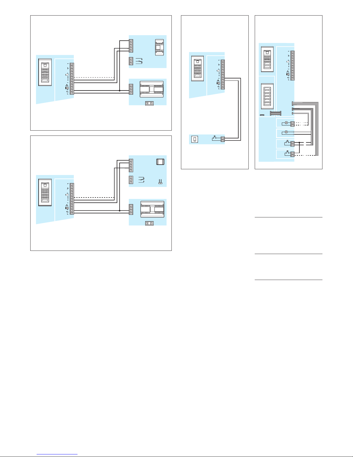
Fig.33 - Connection diagram of
auxiliary door-lock release button
(AE).
Fig.33 - Esquema de conexión del
pulsador auxiliar abrepuerta (AE).
Fig.34 - Colour coding of wires relating to CN3-CN4-CN5.
Fig.34 - Color de los conductores
correspondientes a los cableados
CN3-CN4-CN5.
CN3
C: orange, naranja
G: yellow,amarillo
R: red, rojo
CN4
M: brown, marrón
N: black,negro
CN5
G: yellow,amarillo
H: grey, gris
CBI
CN1
HEP/306
(HEP/312D)
CN3
CN5
CBO
1
N
M
CN4
G
H
KHSO
HEV/301+
…KHPS (…KHPD)
(+KHSO)+
…HEP/306
(…HEP/312D)
B IN
B OUT
2
R
34
A
G
VAS/100
1
2
1
2
HEV/301
(HEVC/301)
(HET/301)
B IN
B OUT
NC
C
NO
C
M1
AC/200
5
6
21
7
14
SW1
L
N
32
B
VLS/101
A
1
2
3
A
G
VAS/100
1
2
1
2
HEV/301
(HEVC/301)
(HET/301)
B IN
B OUT
1
2
3
4
5
L
N
31
Fig.31 - Sample connection of Aux
1 or Aux 2 auxiliary output with relay
unit VLS/101.
Power supply by means of VAS/100.
Fig.31 - Ejemplo de conexión salida
auxiliar Aux 1 ó Aux 2 con la unidad
relé VLS/101.
Alimentación mediante VAS/100.
Fig.32 - Sample connection of Aux
1 or Aux 2 auxiliary output with relay
unit AC/200.
Power supply by means of VAS/100.
Fig.32 - Ejemplo de conexión salida
auxiliar Aux 1 ó Aux 2 con la unidad
relé AC/200.
Alimentación mediante VAS/100.
Page 11
11
12V
HEV/301(HEVC/301)
1
CN1
CN3
CN5
CN4
N
M
SW1 SW2
G
VA/ 301
CN1
M2
B OUT
M1
+
-
B IN
B IN
B OUT
CP
OPHERA(OPHERA/B)
SW1
M1
B
-
+
AL
BUS
LOCAL
SW2
L
N
OPHERAKIT/..
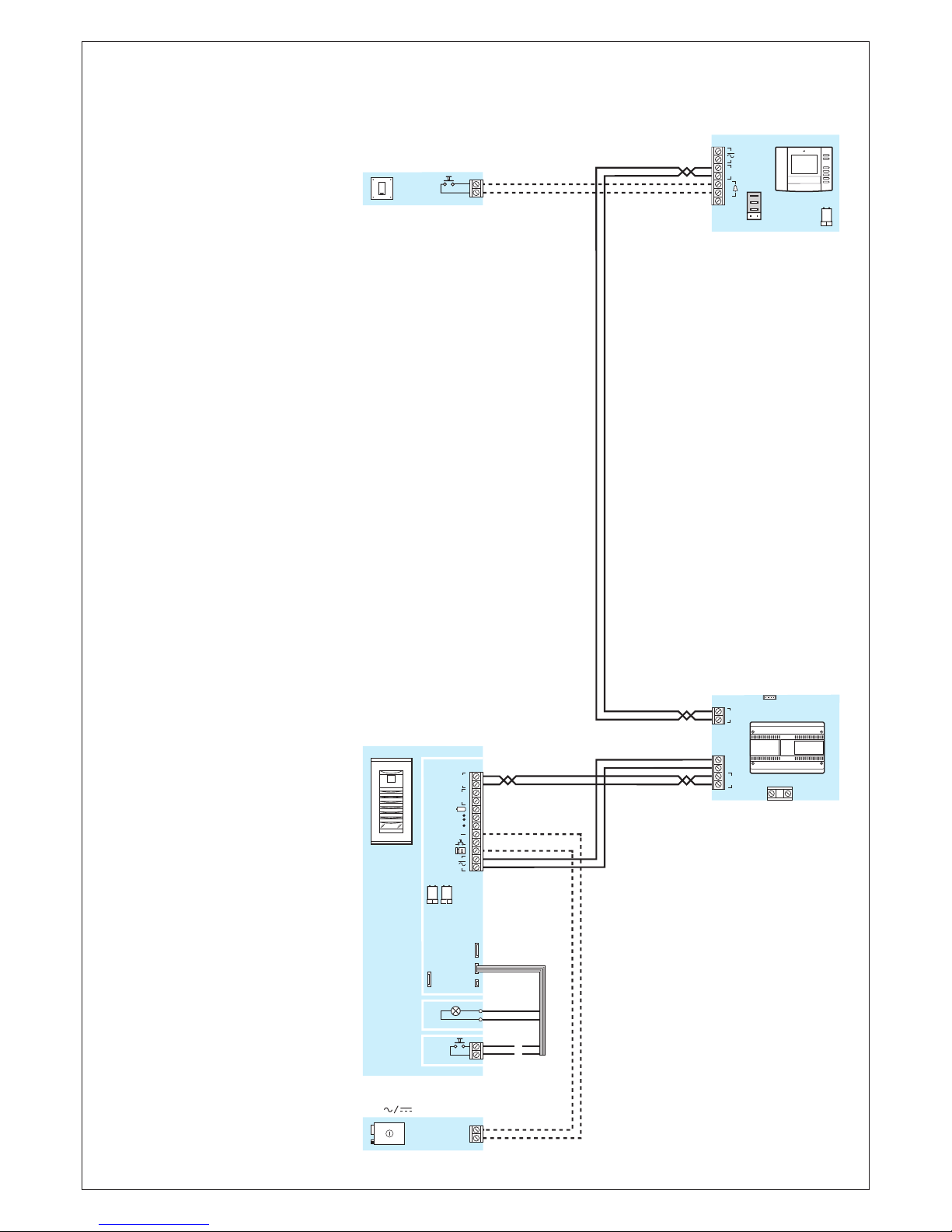
WARNING!
The units included in this kit can also be
used individually to realize multi-family
installations.
Cross section of cables: see entry panel
instructions.
ATENCION!
Los aparatos que componen este kit pueden ser utilizados individualmente para
realizar instalaciones multifamiliares.
Para la sección de los conductores ver las
instrucciones de la placa exterior.
CP: Personal door-bell button.
Pulsador de llamada desde el rellano.
Page 12

12
 Loading...