

Page 1
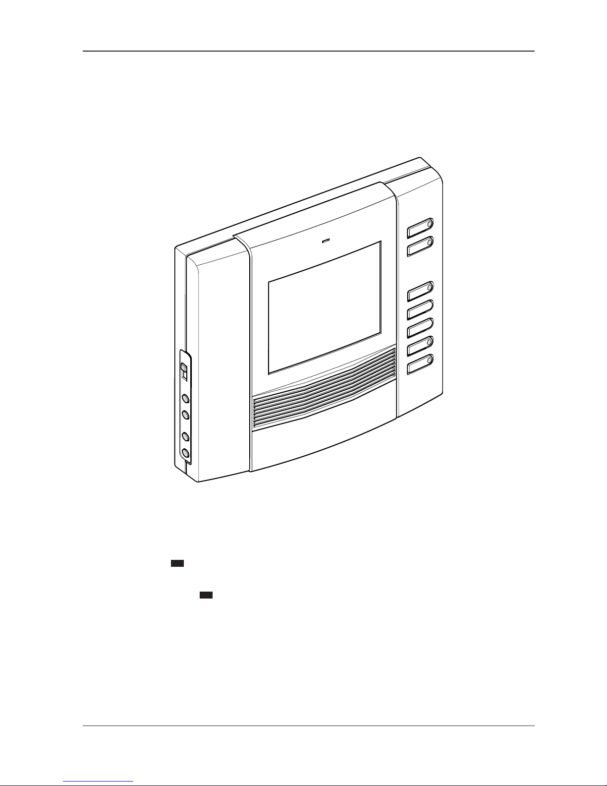
OPHERA
OPHERA/BI
IT
Manuale di Installazione
EN
Installation Manual
24801590 / 28-04-10
Page 2
2
1
10mm
2
Ø
A
B
1
3 4 5
2
1
3
2
IT
INSTALLAZIONE
ATTENZIONE. Si raccomanda di installare il monitor in ambiente asciutto.
Scatola incasso PHI
La scatola può essere installata sia a muro che su
pareti in cartongesso ad un’altezza adeguata all’utente rispettando l’indicazione ALTO indicata sul fondo
della scatola d’incasso.
- Dimensioni: 130x114x53,5 mm.
Installazione a muro
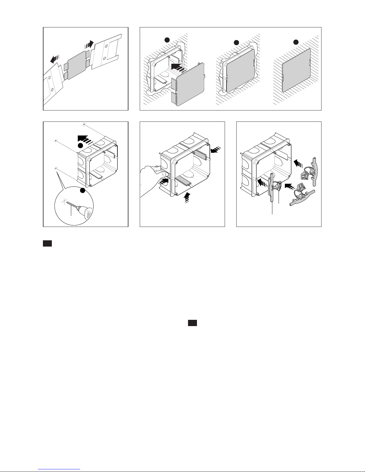
La scatola incasso va murata a filo muro munita della
protezione in dotazione (fig. 2) ricavata nell’interno
imballo (fig. 1).
Installazione su pareti in cartongesso
Premere la scatola sulla parete per ricavare i 4 punti di
riferimento ed effettuare i fori da 10 mm di diametro
(fig. 3).
Tagliare il cartongesso per ricavare il foro di inserimento della scatola.
Eliminare le 3 alette indicate in figura 4.
Inserire nella scatola la parte superiore A dei morsetti
di fissaggio lasciando libera la parte inferiore B (fig. 5).
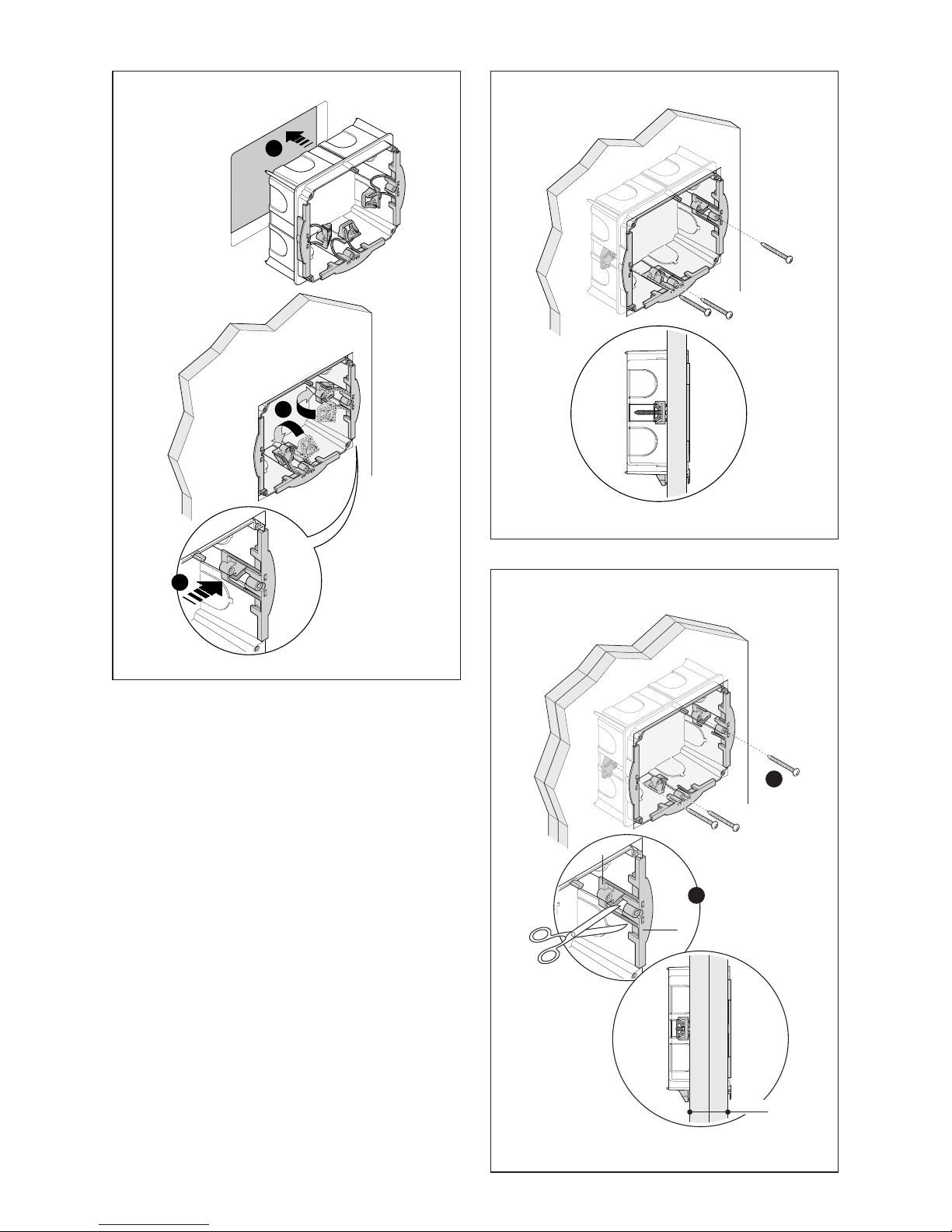
Introdurre nel foro la scatola incasso e applicare la
parte inferiore B (fig. 6).
Bloccare la scatola alla parete utilizzando le viti in
dotazione (fig. 7).
Qualora lo spessore della parete sia maggiore di 2
cm è necessario separare le due parti dei morsetti
di fissaggio posizionando la parte inferiore B come
indicato in figura 8.
EN
INSTALLATION
WARNING. It is recommended to install the monitor in a dry place.
PHI embedding box
The embedding box can be installed in either masonry or plasterboard walls at a height that is suitable
for the user.
Make sure the UP indication is facing the right way
indicated on the bottom of the embedding box.
- Dimensions: 130x114x53,5 mm.
Masonry wall installation
The embedding box should be installed flush with the
wall, and equipped with the provided protection (fig.
2) to be found in the packaging (fig. 1).
Page 3
3
3
2
CLIK!
1
2
1
A
B
>2 cm
6
7
8
Installation on plasterboard walls
Press the box against the wall to get four reference
points where the holes with a 10 mm diameter will
be made (fig. 3).
Cut the plasterboard to obtain the hole where the
box will be inserted.
Remove the three tabs as shown in figure 4.
Insert the upper part A of the fastening clamps into
the box, leaving the lower part B free (fig. 5).
Place the embedding box into the hole and then
apply the lower part B (fig. 6).
Secure the box to the wall with the screws provided
(fig. 7).
If the wall is more than 2 cm thick, the two parts of
the fastening clamps will need to be separated, positioning the lower part B as shown in figure 8.
Page 4
4
OPHERA
OPHERA
OPHERA
9
10
11
IT
Videocitofono OPHERA/BI
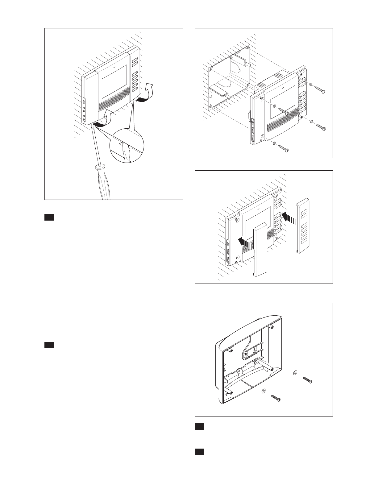
Togliere le due cover come indicato in figura 11.
Effettuare i collegamenti.
Fissare l’apparecchio alla scatola d’incasso utilizzando
le viti in dotazione (fig. 12).
Inserire le cover come indicato in figura 13.
Sostituzione delle cover
L’apparecchio viene fornito con 3 set di cover di
diverso colore intercambiabili.
Per la sostituzione agire come indicato in figura 11
e 13.
EN
OPHERA/BI video handset
Remove the two covers as shown in fig. 11. Wire the
connections.
Fasten the appliance to the embedding box, using
the screws provided (fig. 12).
Insert the covers as shown in fig. 13.
Replace the covers
The appliance is equipped with 3 sets of exchangeable covers in different colours.
To replace, proceed as shown in fig. 11 and 13.
PHKP
IT
- ACCESSORI
Supporto da parete PHKP
EN
ACCESSORIES
Wall support PHKP
Page 5
5
B
SW1
SW2
V
AL
A
+
–
+
–
Rosso
Red
Rot
Rouge
Rojo
Vermelho
Giallo
Yellow
Gelb
Jaune
Amarillo
Amarelo
Bianco
White
Weiß
Blanc
Blanco
Branco
Blu
Blue
Blau
Bleu
Azul
Azul
BUS 18VDC
A
–
V
+
SW1
SW2
A
B
C
IT
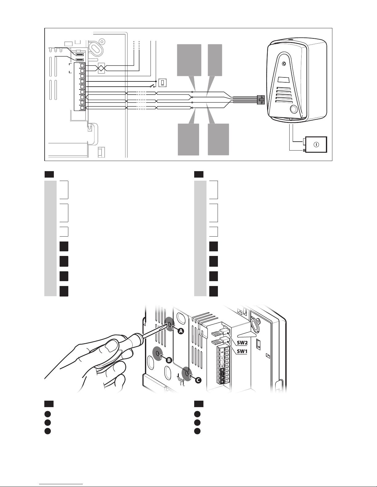
MORSETTIERE
M1
B
Ingresso linea BUS
+
–
Alimentazione locale 18VDC
AL Ingresso allarme
A Uscita audio
–
Uscita –
V Uscita Video
+
Uscita +
EN
TERMINAL BOARDS
M1
B
BUS line input
+
–
Power supply local 18VDC
AL Alarm input
A Audio Output
–
– Output
V Video Output
+
+ Output
IT
- REGOLAZIONE VOLUMI
A
Regolazione volume microfono OPHERA/BI
B
Regolazione volume speaker OPHERA/BI
C
Regolazione volume microfono HEVC/MI
y I volumi dei dispositivi vengono tarati in fabbrica;
agire sulle regolazioni solo se strettamente necessario
EN
ADJUSTING VOLUMES
A
OPHERA/BI microphone volume adjustment
B
OPHERA/BI speaker volume adjustment
C
HEVC/MI microphone volume adjustment
y The volumes of the devices are calibrated at the
factory; act on the adjustments only if necessary
HEVC/MI
OPHERA/BI
OPHERA/BI
Page 6
6
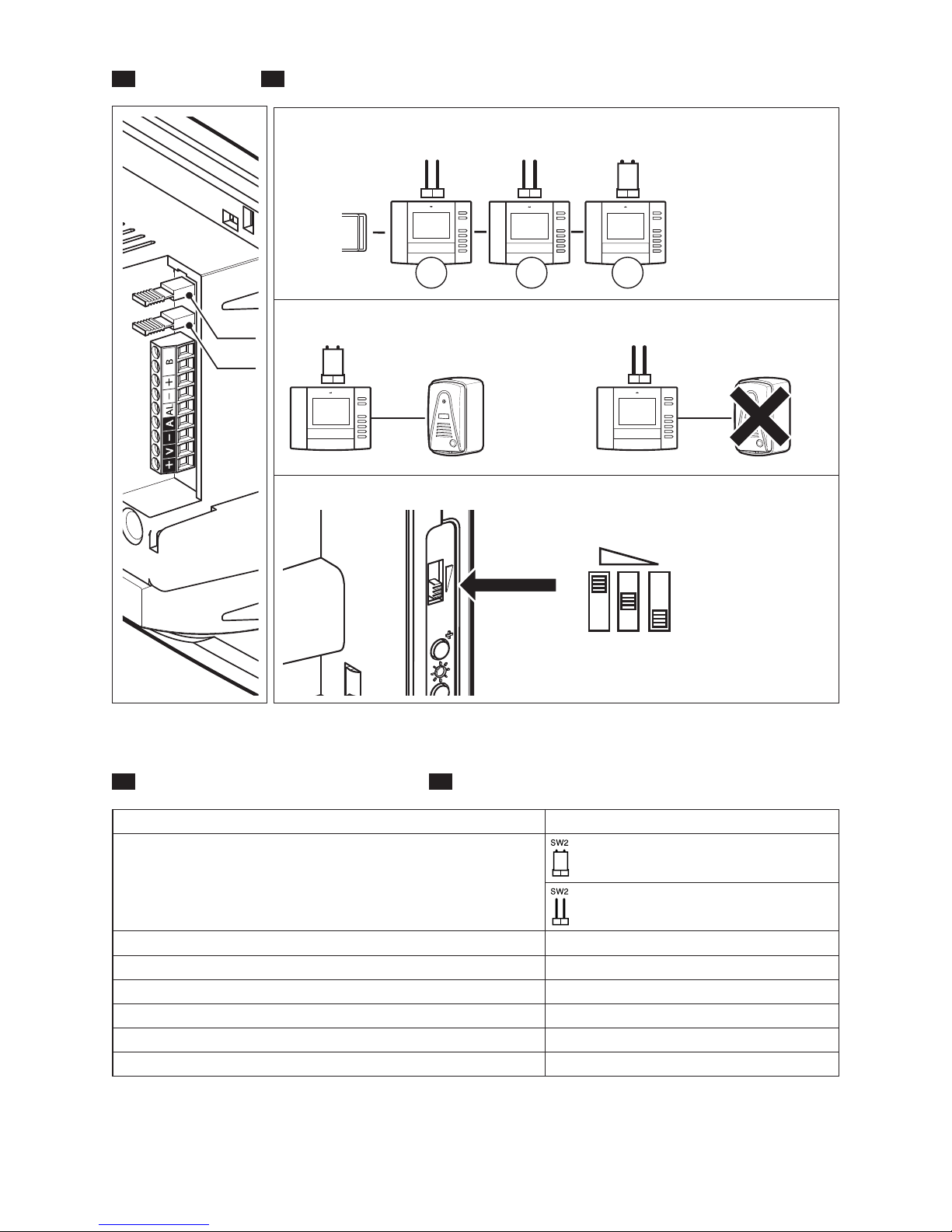
SW1(Resistenza di chiusura) – SW1 (Resistive load termination)
SW2 (Presenza posto esterno) – SW2 (Entry panel presence)
Regolazione suoneria – Adjusting the ring
IT
- SELEZIONI EN SELECTIONS
SW1
SW2
SW1 SW1 SW1
1 2
3
XDV/304
SW2 SW2
Alimentazione - Supply voltage 14-18 VDC
Assorbimento - Absorption
350 mA max (<20 mA stand-by)
200 mA max (<20 mA stand-by)
Dimensioni - Dimensions 158,8x124,8x17,5 mm
Temperatura di stoccaggio - Storage temperature -25 °C +70 °C
Temperatura di funzionamento - Operating temperature 0 °C +35 °C
Grado IP - IP Degree IP 20
Standard video - Standard video PAL/NTSC
Display a colori - Colour display LCD TFT 3,5”-4:3
IT
CARATTERISTICHE TECNICHE – EN TECHNICAL FEATURES
Page 7
7
IT
- PROGRAMMAZIONE – EN PROGRAMMING
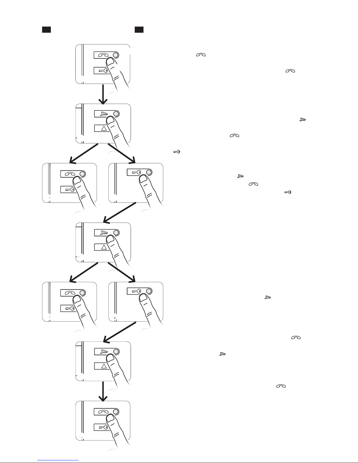
Ingresso in Programmazione. Premere per 5 volte il
pulsante entro 5 s. Un breve segnale acustico conferma l’ingresso in programmazione a.
Accessing programming. Press the button 5 times
within 5 s. A brief acoustic signal will confirm that programming has been accessed a.
Programmazione della melodia associata alla chiamata dal posto esterno (1 segnale acustico). Per
ascoltare in sequenza le melodie premere il tasto b.
Per selezionare la melodia ed uscire dalla programmazione premere il tasto c. Per selezionare la melodia
e proseguire con la programmazione premere il tasto
d.
Programming the melody associated to the call from
the entry panel (1 acoustic signal). To hear the melodies
in sequence, press the key b. To select the melody and
exit programming, press the key c. To select the melody
and continue with programming, press the key d.
Programmazione della melodia associata alla chiamata dal pianerottolo (2 segnali acustici). Per questo
tipo di programmazione e f g procedere come la
“Programmazione della melodia associata alla chiamata
dal posto esterno” precedentemente descritta.
Programming the melody associated with the doorbell (2 acoustic signals). For this type of programming e
f g proceed as previously described for “Programming the
melody associated to the call from the entry panel”.
Programmazione del numero di squilli di chiamata
(3 segnali acustici). Premere il tasto tante volte quanti
sono gli squilli che si è scelto per la chiamata (da 1 a 6
squilli) h. Dopo 3 s dall’ultima pressione del tasto verrà
riprodotta la chiamata selezionata per il numero di squilli
prescelto. Per salvare la melodia scelta ed uscire completamente dalla programmazione premere il tasto i.
Programming the number of call rings (3 acoustic signals). Press the key the number of times equal to the rings
selected for the call (1 to 6 rings) h. 3 s after the key is pressed
the last time, the call selected for the selected number of rings
will be will be reproduced. To save the selected memory and
exit programming completely, press the key i.
y Per la programmazione della chiamata, vedere la
documentazione dei posti esterni.
y For call programming, see the entry panel docu-For call programming, see the entry panel docu-
mentation.
beep
X 5
A
B
E
H
I
C
F
D
G
Page 8

8
BPT S.p.A.
Via Cornia, 1
33079 Sesto al Reghena-PN-Italy
[email protected]
 Loading...