

Page 1
OPHERA LYNEA BASICLYNEANOVAMITHOVAS/100.30
DVC/01
DVC/01 ME
OPHERA LYNEA BASICLYNEANOVAMITHOVAS/100.30
DVC/01
DVC/01 ME
Manuale di Installazione
Installation Manual
Handbuch für den Installateur
Manuel d’Installation
Manual para el Instalador
Manual para o Instalador
BVKIT
04-10-10/24801012
Page 2

2
Page 3

3
INDICE
LYNEA BASIC YVL301 . . . . . . . . . . . . . . . . . PAG. 6
Installazione . . . . . . . . . . . . . . . . . . . . . . . . . . . . . . . . . . . . 6
Morsettiere . . . . . . . . . . . . . . . . . . . . . . . . . . . . . . . . . . . . . 7
Funzione deI connettori . . . . . . . . . . . . . . . . . . . . . . . . . . . 7
Caratteristiche tecniche. . . . . . . . . . . . . . . . . . . . . . . . . . . . 7
Selezioni . . . . . . . . . . . . . . . . . . . . . . . . . . . . . . . . . . . . . . . 8
Accessori . . . . . . . . . . . . . . . . . . . . . . . . . . . . . . . . . . . . . . . 8
Programmazione. . . . . . . . . . . . . . . . . . . . . . . . . . . . . . . . . 9
LYNEA YVYVC . . . . . . . . . . . . . . . . . . . . . . PAG. 10
Installazione . . . . . . . . . . . . . . . . . . . . . . . . . . . . . . . . . . . 10
Morsettiere . . . . . . . . . . . . . . . . . . . . . . . . . . . . . . . . . . . . 11
Funzione deI connettorI . . . . . . . . . . . . . . . . . . . . . . . . . . 11
Selezioni . . . . . . . . . . . . . . . . . . . . . . . . . . . . . . . . . . . . . . 12
Caratteristiche tecniche. . . . . . . . . . . . . . . . . . . . . . . . . . . 12
Accessori . . . . . . . . . . . . . . . . . . . . . . . . . . . . . . . . . . . . . . 12
Programmazione. . . . . . . . . . . . . . . . . . . . . . . . . . . . . . . . 13
OPHERAOPHERA/B . . . . . . . . . . . . . . . . . . . PAG. 14
Installazione . . . . . . . . . . . . . . . . . . . . . . . . . . . . . . . . . . . 14
Accessori . . . . . . . . . . . . . . . . . . . . . . . . . . . . . . . . . . . . . . 16
Morsettiere . . . . . . . . . . . . . . . . . . . . . . . . . . . . . . . . . . . . 17
Selezioni . . . . . . . . . . . . . . . . . . . . . . . . . . . . . . . . . . . . . . 17
Caratteristiche tecniche. . . . . . . . . . . . . . . . . . . . . . . . . . . 18
Programmazione. . . . . . . . . . . . . . . . . . . . . . . . . . . . . . . . 19
NOVA. . . . . . . . . . . . . . . . . . . . . . . . . . . . . . PAG. 20
Installazione . . . . . . . . . . . . . . . . . . . . . . . . . . . . . . . . . . . 20
Morsettiere modulo audio . . . . . . . . . . . . . . . . . . . . . . . . 23
Morsettiere modulo video. . . . . . . . . . . . . . . . . . . . . . . . . 23
Funzione dei connettori . . . . . . . . . . . . . . . . . . . . . . . . . . 23
Selezioni modulo audio. . . . . . . . . . . . . . . . . . . . . . . . . . . 24
Selezioni modulo video. . . . . . . . . . . . . . . . . . . . . . . . . . . 24
Caratteristiche tecniche. . . . . . . . . . . . . . . . . . . . . . . . . . . 24
MITHO . . . . . . . . . . . . . . . . . . . . . . . . . . . . . PAG. 26
Installazione . . . . . . . . . . . . . . . . . . . . . . . . . . . . . . . . . . . 26
Morsettiere . . . . . . . . . . . . . . . . . . . . . . . . . . . . . . . . . . . . 28
Selezioni . . . . . . . . . . . . . . . . . . . . . . . . . . . . . . . . . . . . . . 28
Caratteristiche tecniche. . . . . . . . . . . . . . . . . . . . . . . . . . . 29
Messa in servizio . . . . . . . . . . . . . . . . . . . . . . . . . . . . . . . . 29
Accessori . . . . . . . . . . . . . . . . . . . . . . . . . . . . . . . . . . . . . . 29
VAS/100.30. . . . . . . . . . . . . . . . . . . . . . . . . . PAG. 30
Installazione . . . . . . . . . . . . . . . . . . . . . . . . . . . . . . . . . . . 30
DVC/01DVC/01 ME . . . . . . . . . . . . . . . . . . . . PAG. 32
Installazione da parete . . . . . . . . . . . . . . . . . . . . . . . . . . . 32
Installazione da incasso. . . . . . . . . . . . . . . . . . . . . . . . . . . 33
Aancabilità a parete . . . . . . . . . . . . . . . . . . . . . . . . . . . . 34
Aancabilità a incasso . . . . . . . . . . . . . . . . . . . . . . . . . . . 36
Accessori . . . . . . . . . . . . . . . . . . . . . . . . . . . . . . . . . . . . . . 37
Funzione dei morsetti . . . . . . . . . . . . . . . . . . . . . . . . . . . . 38
Regolazioni e funzioni dei led . . . . . . . . . . . . . . . . . . . . . . 39
Caratteristiche Tecniche . . . . . . . . . . . . . . . . . . . . . . . . . . 39
Programmazione. . . . . . . . . . . . . . . . . . . . . . . . . . . . . . . . 40
CONTENTS
LYNEA BASIC YVL301 . . . . . . . . . . . . . . . . . PAG. 6
Installation. . . . . . . . . . . . . . . . . . . . . . . . . . . . . . . . . . . . . . 6
Terminal boards. . . . . . . . . . . . . . . . . . . . . . . . . . . . . . . . . . 7
Function of connector . . . . . . . . . . . . . . . . . . . . . . . . . . . . . 7
Technical features . . . . . . . . . . . . . . . . . . . . . . . . . . . . . . . . 7
Selections . . . . . . . . . . . . . . . . . . . . . . . . . . . . . . . . . . . . . . 8
Accessories . . . . . . . . . . . . . . . . . . . . . . . . . . . . . . . . . . . . . 8
Programming. . . . . . . . . . . . . . . . . . . . . . . . . . . . . . . . . . . . 9
LYNEA YVYVC . . . . . . . . . . . . . . . . . . . . . . PAG. 10
Installation. . . . . . . . . . . . . . . . . . . . . . . . . . . . . . . . . . . . . .10
Terminal boards. . . . . . . . . . . . . . . . . . . . . . . . . . . . . . . . . .11
Function of connectors . . . . . . . . . . . . . . . . . . . . . . . . . . . .11
Selections . . . . . . . . . . . . . . . . . . . . . . . . . . . . . . . . . . . . . .12
Technical features . . . . . . . . . . . . . . . . . . . . . . . . . . . . . . . .12
Accessories . . . . . . . . . . . . . . . . . . . . . . . . . . . . . . . . . . . . .12
Programming. . . . . . . . . . . . . . . . . . . . . . . . . . . . . . . . . . . .13
OPHERAOPHERA/B . . . . . . . . . . . . . . . . . . . PAG. 14
Installation. . . . . . . . . . . . . . . . . . . . . . . . . . . . . . . . . . . . . .14
Accessories . . . . . . . . . . . . . . . . . . . . . . . . . . . . . . . . . . . . .16
Terminal boards. . . . . . . . . . . . . . . . . . . . . . . . . . . . . . . . . .17
Selections . . . . . . . . . . . . . . . . . . . . . . . . . . . . . . . . . . . . . .17
Technical features . . . . . . . . . . . . . . . . . . . . . . . . . . . . . . . .18
Programming. . . . . . . . . . . . . . . . . . . . . . . . . . . . . . . . . . . .19
NOVA. . . . . . . . . . . . . . . . . . . . . . . . . . . . . . PAG. 20
Installation. . . . . . . . . . . . . . . . . . . . . . . . . . . . . . . . . . . . . .20
Audio module terminal board. . . . . . . . . . . . . . . . . . . . . . .23
Video module terminal board . . . . . . . . . . . . . . . . . . . . . . .23
Function of connectors . . . . . . . . . . . . . . . . . . . . . . . . . . . .23
Audio module selections. . . . . . . . . . . . . . . . . . . . . . . . . . .24
Video module selections . . . . . . . . . . . . . . . . . . . . . . . . . . .24
Technical features . . . . . . . . . . . . . . . . . . . . . . . . . . . . . . . .24
MITHO . . . . . . . . . . . . . . . . . . . . . . . . . . . . . PAG. 26
Installation. . . . . . . . . . . . . . . . . . . . . . . . . . . . . . . . . . . . . .26
Terminal boards. . . . . . . . . . . . . . . . . . . . . . . . . . . . . . . . . .28
Selections . . . . . . . . . . . . . . . . . . . . . . . . . . . . . . . . . . . . . .28
Technical features . . . . . . . . . . . . . . . . . . . . . . . . . . . . . . . .29
Commissioning . . . . . . . . . . . . . . . . . . . . . . . . . . . . . . . . . .29
Accessories . . . . . . . . . . . . . . . . . . . . . . . . . . . . . . . . . . . . .29
VAS/100.30. . . . . . . . . . . . . . . . . . . . . . . . . . PAG. 30
Installation. . . . . . . . . . . . . . . . . . . . . . . . . . . . . . . . . . . . . .30
DVC/01DVC/01 ME . . . . . . . . . . . . . . . . . . . . PAG. 32
Wall mounting . . . . . . . . . . . . . . . . . . . . . . . . . . . . . . . . . . .32
Recessed installation. . . . . . . . . . . . . . . . . . . . . . . . . . . . . . 33
Side-by-side wall
installation. . . . . . . . . . . . . . . . . . . . . . . . . . . . . . . . . . . . . .34
Side-by-side recessed
Installation. . . . . . . . . . . . . . . . . . . . . . . . . . . . . . . . . . . . . .36
Accessories . . . . . . . . . . . . . . . . . . . . . . . . . . . . . . . . . . . . .37
Terminal function . . . . . . . . . . . . . . . . . . . . . . . . . . . . . . . .38
Led functions and adjustments. . . . . . . . . . . . . . . . . . . . . . 39
Technical Features . . . . . . . . . . . . . . . . . . . . . . . . . . . . . . . .39
Programming. . . . . . . . . . . . . . . . . . . . . . . . . . . . . . . . . . . .40
Page 4

4
INHALTSVERZEICHNIS
LYNEA BASIC YVL301 . . . . . . . . . . . . . . . . . PAG. 6
Installation. . . . . . . . . . . . . . . . . . . . . . . . . . . . . . . . . . . . . . 6
Klemmenbretter . . . . . . . . . . . . . . . . . . . . . . . . . . . . . . . . . 7
Funktion der steckverbinder. . . . . . . . . . . . . . . . . . . . . . . . 7
Technische merkmale . . . . . . . . . . . . . . . . . . . . . . . . . . . . . 7
Wahlen. . . . . . . . . . . . . . . . . . . . . . . . . . . . . . . . . . . . . . . . . 8
Zubehör . . . . . . . . . . . . . . . . . . . . . . . . . . . . . . . . . . . . . . . . 8
Programmierung . . . . . . . . . . . . . . . . . . . . . . . . . . . . . . . . . 9
LYNEA YVYVC . . . . . . . . . . . . . . . . . . . . . . PAG. 10
Installation. . . . . . . . . . . . . . . . . . . . . . . . . . . . . . . . . . . . . .10
Klemmenbretter . . . . . . . . . . . . . . . . . . . . . . . . . . . . . . . . .11
Funktion der steckverbinder. . . . . . . . . . . . . . . . . . . . . . . .11
Wahlen. . . . . . . . . . . . . . . . . . . . . . . . . . . . . . . . . . . . . . . . .12
Technische merkmale . . . . . . . . . . . . . . . . . . . . . . . . . . . . .12
Zubehör . . . . . . . . . . . . . . . . . . . . . . . . . . . . . . . . . . . . . . . .12
Programmierung . . . . . . . . . . . . . . . . . . . . . . . . . . . . . . . . .13
OPHERAOPHERA/B . . . . . . . . . . . . . . . . . . . PAG. 14
Installation. . . . . . . . . . . . . . . . . . . . . . . . . . . . . . . . . . . . . .14
Zubehör . . . . . . . . . . . . . . . . . . . . . . . . . . . . . . . . . . . . . . . .16
Klemmenbretter . . . . . . . . . . . . . . . . . . . . . . . . . . . . . . . . .17
Wahlen. . . . . . . . . . . . . . . . . . . . . . . . . . . . . . . . . . . . . . . . .17
Technische merkmale . . . . . . . . . . . . . . . . . . . . . . . . . . . . .18
Programmierung . . . . . . . . . . . . . . . . . . . . . . . . . . . . . . . . .19
NOVA. . . . . . . . . . . . . . . . . . . . . . . . . . . . . . PAG. 20
Installation. . . . . . . . . . . . . . . . . . . . . . . . . . . . . . . . . . . . . .20
Klemmleisten Audio-modul . . . . . . . . . . . . . . . . . . . . . . . .23
Klemmleisten Video-modul. . . . . . . . . . . . . . . . . . . . . . . . .23
Funktion der steckverbinder. . . . . . . . . . . . . . . . . . . . . . . .23
Wahlen Audiomodul . . . . . . . . . . . . . . . . . . . . . . . . . . . . . . 24
Wahlen Videomodul . . . . . . . . . . . . . . . . . . . . . . . . . . . . . . 24
Technische merkmale . . . . . . . . . . . . . . . . . . . . . . . . . . . . .24
MITHO . . . . . . . . . . . . . . . . . . . . . . . . . . . . . PAG. 26
Installation. . . . . . . . . . . . . . . . . . . . . . . . . . . . . . . . . . . . . .26
Klemmenbretter . . . . . . . . . . . . . . . . . . . . . . . . . . . . . . . . .28
Wahlen. . . . . . . . . . . . . . . . . . . . . . . . . . . . . . . . . . . . . . . . .28
Technische merkmale . . . . . . . . . . . . . . . . . . . . . . . . . . . . .29
Inbetriebnahme. . . . . . . . . . . . . . . . . . . . . . . . . . . . . . . . . .29
Programmierung . . . . . . . . . . . . . . . . . . . . . . . . . . . . . . . . .29
VAS/100.30. . . . . . . . . . . . . . . . . . . . . . . . . . PAG. 30
Installation. . . . . . . . . . . . . . . . . . . . . . . . . . . . . . . . . . . . . .30
DVC/01DVC/01 ME . . . . . . . . . . . . . . . . . . . . PAG. 32
Montage aufputzgehäuse . . . . . . . . . . . . . . . . . . . . . . . . . .32
Unterputzmontage . . . . . . . . . . . . . . . . . . . . . . . . . . . . . . .33
Aneinanderreihen bei
Aufputzmontage . . . . . . . . . . . . . . . . . . . . . . . . . . . . . . . . .34
Aneinanderreihen bei Unterputzmontage . . . . . . . . . . . . .36
Zubehör . . . . . . . . . . . . . . . . . . . . . . . . . . . . . . . . . . . . . . . .37
Belegung der klemmleisten . . . . . . . . . . . . . . . . . . . . . . . . 38
Einstellungen und funktionen der leds. . . . . . . . . . . . . . . .39
Technische Merkmale . . . . . . . . . . . . . . . . . . . . . . . . . . . . .39
Programmierung . . . . . . . . . . . . . . . . . . . . . . . . . . . . . . . . .40
SOMMAIRE
LYNEA BASIC YVL301 . . . . . . . . . . . . . . . . . PAG. 6
Installation. . . . . . . . . . . . . . . . . . . . . . . . . . . . . . . . . . . . . . 6
Borniers . . . . . . . . . . . . . . . . . . . . . . . . . . . . . . . . . . . . . . . . 7
Fonction de connecteur. . . . . . . . . . . . . . . . . . . . . . . . . . . . 7
Caractéristiques Techniques . . . . . . . . . . . . . . . . . . . . . . . . 7
Sélections . . . . . . . . . . . . . . . . . . . . . . . . . . . . . . . . . . . . . . 8
Accessoires . . . . . . . . . . . . . . . . . . . . . . . . . . . . . . . . . . . . . 8
Programmation . . . . . . . . . . . . . . . . . . . . . . . . . . . . . . . . . . 9
LYNEA YVYVC . . . . . . . . . . . . . . . . . . . . . . PAG. 10
Installation. . . . . . . . . . . . . . . . . . . . . . . . . . . . . . . . . . . . . .10
Borniers . . . . . . . . . . . . . . . . . . . . . . . . . . . . . . . . . . . . . . . .11
Fonction des connecteurs . . . . . . . . . . . . . . . . . . . . . . . . . .11
Sélections . . . . . . . . . . . . . . . . . . . . . . . . . . . . . . . . . . . . . .12
Caractéristiques techniques . . . . . . . . . . . . . . . . . . . . . . . .12
Accessoires . . . . . . . . . . . . . . . . . . . . . . . . . . . . . . . . . . . . .12
Programmation . . . . . . . . . . . . . . . . . . . . . . . . . . . . . . . . . .13
OPHERAOPHERA/B . . . . . . . . . . . . . . . . . . . PAG. 14
Installation. . . . . . . . . . . . . . . . . . . . . . . . . . . . . . . . . . . . . .14
Accessoires . . . . . . . . . . . . . . . . . . . . . . . . . . . . . . . . . . . . .16
Borniers . . . . . . . . . . . . . . . . . . . . . . . . . . . . . . . . . . . . . . . .17
Sélections . . . . . . . . . . . . . . . . . . . . . . . . . . . . . . . . . . . . . .17
Caractéristiques techniques . . . . . . . . . . . . . . . . . . . . . . . .18
Programmation . . . . . . . . . . . . . . . . . . . . . . . . . . . . . . . . . .19
NOVA. . . . . . . . . . . . . . . . . . . . . . . . . . . . . . PAG. 20
Installation. . . . . . . . . . . . . . . . . . . . . . . . . . . . . . . . . . . . . .20
Borniers module audio . . . . . . . . . . . . . . . . . . . . . . . . . . . .23
Borniers module vidéo . . . . . . . . . . . . . . . . . . . . . . . . . . . .23
Fonction des connecteurs . . . . . . . . . . . . . . . . . . . . . . . . . .23
Sélections module audio . . . . . . . . . . . . . . . . . . . . . . . . . . .24
Sélection module vidéo. . . . . . . . . . . . . . . . . . . . . . . . . . . . 24
Caractéristiques techniques . . . . . . . . . . . . . . . . . . . . . . . .24
MITHO . . . . . . . . . . . . . . . . . . . . . . . . . . . . . PAG. 26
Installation. . . . . . . . . . . . . . . . . . . . . . . . . . . . . . . . . . . . . .27
Borniers . . . . . . . . . . . . . . . . . . . . . . . . . . . . . . . . . . . . . . . .28
Sélections . . . . . . . . . . . . . . . . . . . . . . . . . . . . . . . . . . . . . .28
Caractéristiques techniques . . . . . . . . . . . . . . . . . . . . . . . .29
Mise en service . . . . . . . . . . . . . . . . . . . . . . . . . . . . . . . . . .29
Accessoires . . . . . . . . . . . . . . . . . . . . . . . . . . . . . . . . . . . . .29
VAS/100.30. . . . . . . . . . . . . . . . . . . . . . . . . . PAG. 30
Installation. . . . . . . . . . . . . . . . . . . . . . . . . . . . . . . . . . . . . .30
DVC/01DVC/01 ME . . . . . . . . . . . . . . . . . . . . PAG. 32
Installation murale . . . . . . . . . . . . . . . . . . . . . . . . . . . . . . . 32
Installation à encastrer . . . . . . . . . . . . . . . . . . . . . . . . . . . .33
Juxtaposition murale . . . . . . . . . . . . . . . . . . . . . . . . . . . . .34
Juxtaposition à . . . . . . . . . . . . . . . . . . . . . . . . . . . . . . . . . .37
Encastrement. . . . . . . . . . . . . . . . . . . . . . . . . . . . . . . . . . . .37
Accessoires . . . . . . . . . . . . . . . . . . . . . . . . . . . . . . . . . . . . .37
Fonctions des bornes. . . . . . . . . . . . . . . . . . . . . . . . . . . . . .38
Réglages et fonctions des leds . . . . . . . . . . . . . . . . . . . . . .39
Caractéristiques Techniques . . . . . . . . . . . . . . . . . . . . . . . .39
Programmation . . . . . . . . . . . . . . . . . . . . . . . . . . . . . . . . . .40
Page 5

5
ÍNDICE
LYNEA BASIC YVL301 . . . . . . . . . . . . . . . . . PAG. 6
Instalación . . . . . . . . . . . . . . . . . . . . . . . . . . . . . . . . . . . . . . 6
Borneras. . . . . . . . . . . . . . . . . . . . . . . . . . . . . . . . . . . . . . . . 7
Función de conectore . . . . . . . . . . . . . . . . . . . . . . . . . . . . . 7
Características técnicas . . . . . . . . . . . . . . . . . . . . . . . . . . . . 7
Selecciones . . . . . . . . . . . . . . . . . . . . . . . . . . . . . . . . . . . . . 8
Accesorios . . . . . . . . . . . . . . . . . . . . . . . . . . . . . . . . . . . . . . 8
Programación . . . . . . . . . . . . . . . . . . . . . . . . . . . . . . . . . . . 9
LYNEA YVYVC . . . . . . . . . . . . . . . . . . . . . . PAG. 10
Instalación . . . . . . . . . . . . . . . . . . . . . . . . . . . . . . . . . . . . . .10
Borneras. . . . . . . . . . . . . . . . . . . . . . . . . . . . . . . . . . . . . . . .11
Función de los conectores . . . . . . . . . . . . . . . . . . . . . . . . . .11
Selecciones . . . . . . . . . . . . . . . . . . . . . . . . . . . . . . . . . . . . . 12
Características técnicas . . . . . . . . . . . . . . . . . . . . . . . . . . . .12
Accesorios . . . . . . . . . . . . . . . . . . . . . . . . . . . . . . . . . . . . . .12
Programación . . . . . . . . . . . . . . . . . . . . . . . . . . . . . . . . . . .13
OPHERAOPHERA/B . . . . . . . . . . . . . . . . . . . PAG. 14
Instalación . . . . . . . . . . . . . . . . . . . . . . . . . . . . . . . . . . . . . .15
Accesorios . . . . . . . . . . . . . . . . . . . . . . . . . . . . . . . . . . . . . .16
Borneras. . . . . . . . . . . . . . . . . . . . . . . . . . . . . . . . . . . . . . . .17
Selecciones . . . . . . . . . . . . . . . . . . . . . . . . . . . . . . . . . . . . . 17
Características técnicas . . . . . . . . . . . . . . . . . . . . . . . . . . . .18
Programación . . . . . . . . . . . . . . . . . . . . . . . . . . . . . . . . . . .19
NOVA. . . . . . . . . . . . . . . . . . . . . . . . . . . . . . PAG. 20
Instalación . . . . . . . . . . . . . . . . . . . . . . . . . . . . . . . . . . . . . .20
Borneras módulo audio. . . . . . . . . . . . . . . . . . . . . . . . . . . .23
Borneras módulo vídeo . . . . . . . . . . . . . . . . . . . . . . . . . . . .23
Función de los conectores . . . . . . . . . . . . . . . . . . . . . . . . . .23
Selecciones módulo audio. . . . . . . . . . . . . . . . . . . . . . . . . .24
Selecciones módulo vídeo. . . . . . . . . . . . . . . . . . . . . . . . . . 24
Características técnicas . . . . . . . . . . . . . . . . . . . . . . . . . . . .24
MITHO . . . . . . . . . . . . . . . . . . . . . . . . . . . . . PAG. 26
Instalación . . . . . . . . . . . . . . . . . . . . . . . . . . . . . . . . . . . . . .27
Borneras. . . . . . . . . . . . . . . . . . . . . . . . . . . . . . . . . . . . . . . .28
Selecciones . . . . . . . . . . . . . . . . . . . . . . . . . . . . . . . . . . . . . 28
Características técnicas . . . . . . . . . . . . . . . . . . . . . . . . . . . .29
Puesta en servicio . . . . . . . . . . . . . . . . . . . . . . . . . . . . . . . .29
Accesorios . . . . . . . . . . . . . . . . . . . . . . . . . . . . . . . . . . . . . .29
VAS/100.30. . . . . . . . . . . . . . . . . . . . . . . . . . PAG. 30
Instalación . . . . . . . . . . . . . . . . . . . . . . . . . . . . . . . . . . . . . .30
DVC/01DVC/01 ME . . . . . . . . . . . . . . . . . . . . PAG. 32
Instalación sobre pared. . . . . . . . . . . . . . . . . . . . . . . . . . . .32
Instalación empotrada . . . . . . . . . . . . . . . . . . . . . . . . . . . .33
Instalación contigua
Sobre pared . . . . . . . . . . . . . . . . . . . . . . . . . . . . . . . . . . . . .35
Instalación contigua . . . . . . . . . . . . . . . . . . . . . . . . . . . . . .37
Empotrad. . . . . . . . . . . . . . . . . . . . . . . . . . . . . . . . . . . . . . .37
Accesorios . . . . . . . . . . . . . . . . . . . . . . . . . . . . . . . . . . . . . .37
Función de los bornes . . . . . . . . . . . . . . . . . . . . . . . . . . . . .38
Ajustes y funciones de los leds . . . . . . . . . . . . . . . . . . . . . .39
Características Técnicas. . . . . . . . . . . . . . . . . . . . . . . . . . . .39
Programación . . . . . . . . . . . . . . . . . . . . . . . . . . . . . . . . . . .40
ÍNDICE
LYNEA BASIC YVL301 . . . . . . . . . . . . . . . . . PAG. 6
Instalação . . . . . . . . . . . . . . . . . . . . . . . . . . . . . . . . . . . . . . 6
Réguas de bornes . . . . . . . . . . . . . . . . . . . . . . . . . . . . . . . . 7
Função de conectore . . . . . . . . . . . . . . . . . . . . . . . . . . . . . . 7
Características técnicas . . . . . . . . . . . . . . . . . . . . . . . . . . . . 7
Selecções . . . . . . . . . . . . . . . . . . . . . . . . . . . . . . . . . . . . . . . 8
Acessórios . . . . . . . . . . . . . . . . . . . . . . . . . . . . . . . . . . . . . . 8
Programação . . . . . . . . . . . . . . . . . . . . . . . . . . . . . . . . . . . . 9
LYNEA YVYVC . . . . . . . . . . . . . . . . . . . . . . PAG. 10
Instalação . . . . . . . . . . . . . . . . . . . . . . . . . . . . . . . . . . . . . .10
Réguas de bornes . . . . . . . . . . . . . . . . . . . . . . . . . . . . . . . .11
Função dos conectores . . . . . . . . . . . . . . . . . . . . . . . . . . . .11
Selecções . . . . . . . . . . . . . . . . . . . . . . . . . . . . . . . . . . . . . . .12
Características técnicas . . . . . . . . . . . . . . . . . . . . . . . . . . . .12
Acessórios . . . . . . . . . . . . . . . . . . . . . . . . . . . . . . . . . . . . . .12
Programação . . . . . . . . . . . . . . . . . . . . . . . . . . . . . . . . . . . .13
OPHERAOPHERA/B . . . . . . . . . . . . . . . . . . . PAG. 14
Instalação . . . . . . . . . . . . . . . . . . . . . . . . . . . . . . . . . . . . . .15
Acessórios . . . . . . . . . . . . . . . . . . . . . . . . . . . . . . . . . . . . . .16
Réguas de bornes . . . . . . . . . . . . . . . . . . . . . . . . . . . . . . . .17
Selecções . . . . . . . . . . . . . . . . . . . . . . . . . . . . . . . . . . . . . . .17
Características técnicas . . . . . . . . . . . . . . . . . . . . . . . . . . . .18
Programação . . . . . . . . . . . . . . . . . . . . . . . . . . . . . . . . . . . .19
NOVA. . . . . . . . . . . . . . . . . . . . . . . . . . . . . . PAG. 20
Instalação . . . . . . . . . . . . . . . . . . . . . . . . . . . . . . . . . . . . . .20
Painéis de terminais . . . . . . . . . . . . . . . . . . . . . . . . . . . . . .23
módulo áudio . . . . . . . . . . . . . . . . . . . . . . . . . . . . . . . . . . .23
Painéis de terminais . . . . . . . . . . . . . . . . . . . . . . . . . . . . . .23
módulo vídeo. . . . . . . . . . . . . . . . . . . . . . . . . . . . . . . . . . . .23
Função dos conectores . . . . . . . . . . . . . . . . . . . . . . . . . . . .23
Selecções módulo áudio . . . . . . . . . . . . . . . . . . . . . . . . . . .24
Selecções módulo vídeo . . . . . . . . . . . . . . . . . . . . . . . . . . .24
Características técnicas . . . . . . . . . . . . . . . . . . . . . . . . . . . .24
MITHO . . . . . . . . . . . . . . . . . . . . . . . . . . . . . PAG. 26
Instalação . . . . . . . . . . . . . . . . . . . . . . . . . . . . . . . . . . . . . .27
Réguas de bornes . . . . . . . . . . . . . . . . . . . . . . . . . . . . . . . .28
Selecções . . . . . . . . . . . . . . . . . . . . . . . . . . . . . . . . . . . . . . .28
Características técnicas . . . . . . . . . . . . . . . . . . . . . . . . . . . .29
Colocação em serviço . . . . . . . . . . . . . . . . . . . . . . . . . . . . . 29
Acessórios . . . . . . . . . . . . . . . . . . . . . . . . . . . . . . . . . . . . . .29
VAS/100.30. . . . . . . . . . . . . . . . . . . . . . . . . . PAG. 30
Instalação . . . . . . . . . . . . . . . . . . . . . . . . . . . . . . . . . . . . . .30
DVC/01DVC/01 ME . . . . . . . . . . . . . . . . . . . . PAG. 32
Instalação de parede . . . . . . . . . . . . . . . . . . . . . . . . . . . . . .32
Instalação de embutir . . . . . . . . . . . . . . . . . . . . . . . . . . . . .34
Montagem lado a lado
De parede . . . . . . . . . . . . . . . . . . . . . . . . . . . . . . . . . . . . . .35
Montagem lado a lado . . . . . . . . . . . . . . . . . . . . . . . . . . . .37
De embutir. . . . . . . . . . . . . . . . . . . . . . . . . . . . . . . . . . . . . . 37
Acessórios . . . . . . . . . . . . . . . . . . . . . . . . . . . . . . . . . . . . . .37
Função dos bornes. . . . . . . . . . . . . . . . . . . . . . . . . . . . . . . .38
Regulações e funções dos leds . . . . . . . . . . . . . . . . . . . . . .39
Características Técnicas. . . . . . . . . . . . . . . . . . . . . . . . . . . .39
Programação . . . . . . . . . . . . . . . . . . . . . . . . . . . . . . . . . . . .40
Page 6
OPHERALYNEA BASIC LYNEA NOVA MITHO VAS/100.30
DVC/01
DVC/01 ME
LYNEABASIC
LYNEA BASIC YVL301
IT
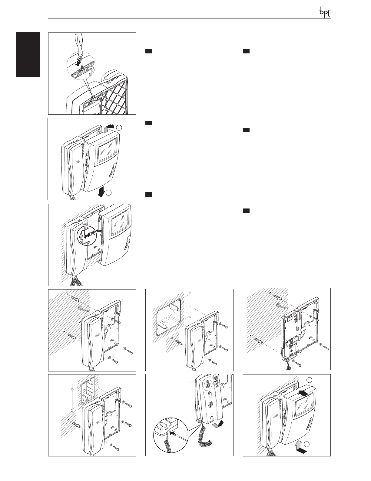
INSTALLAZIONE
ATTENZIONE. Si raccomanda di installare il
monitor in ambiente asciutto.
Aprire il videocitofono come indicato in figura 1
e 2. Togliere il connettore (fig. 3) e installare il videocitofono come indicato in figura 4, 5 e 6.
Per un fissaggio ancora più stabile rimuovere il
supporto cornetta con un cacciavite attraverso
l’apposita feritoia (fig. 7) e fissare il videocitofono
come indicato in figura 8.
Collegare (fig. 3) e rimontare il videocitofono
come indicato in figura 9.
EN
INSTALLATION
WARNING. It is recommended to install the
monitor in a dry place.
Open the video entry control as shown in figures 1
and 2. Remove the connector (fig. 3) and install the
video entry control as shown in figures 4, 5 and 6.
For even more secure fastening, remove the receiver support with a screwdriver through the
slot (fig. 7) and fasten the video entry control as
shown in figure 8.
Connect (fig. 3) an re-install the video entry control as shown in figure 9.
DE
INSTALLATION
ACHTUNG. Es wird empfohlen den Monitor
an einer geschützten Stelle zu installieren.
Die Videosprechanlage wie in den Abbildungen 1
und 2 gezeigt, öffnen. Den Steckverbinder (Abb.
3) entfernen und die Videosprechanlage wie in
den Abbildungen 4, 5 und 6 gezeigt, installieren.
Für eine stabilere Befestigung die Hörerhalterung mit einem Schraubenzieher über den
entsprechenden Schlitz (Abb. 7) abnehmen und
die Videosprechanlage wie in der Abbildung 8
gezeigt, befestigen.
Die Videosprechanlage wie in der Abbildung 9
gezeigt, anschließen (Abb. 3) und wieder montieren.
FR
INSTALLATION
ATTENTION. Le moniteur doit être installé
dans une pièce séche.
Ouvrir le portier vidéo comme indiqué aux figures 1 et 2. Enlever le connecteur (fig. 3) et installer
le portier vidéo comme indiqué aux figures 4, 5
et 6.
Pour fixer de manière encore plus stable, enlever
le support du combiné à l’aide d’un tournevis à
travers la fente prévue à cet effet (fig. 7) et fixer le
portier vidéo comme indiqué à la figure 8.
Raccorder (fig. 3) et remonter le portier vidéo
comme indiqué à la figure 9.
ES
INSTALACIÓN
ATENCION. Se recomienda instalar el monitor en un ambiente seco.
Abra el videoportero electrónico como se indica
en las figuras 1 y 2. Extraiga el conector (fig. 3) e
instale el videoportero electrónico como se indica en las figuras 4, 5 y 6.
Para una fijación aún más estable, retire el soporte del auricular introduciendo un destornillador
a través de la ranura (fig. 7) y fije el videoportero
electrónico como se indica en la figura 8.
Conecte (fig. 3) y vuelva a montar el videoportero electrónico como se indica en la figura 9.
PT
INSTALAÇÃO
ATENÇÃO. Se aconselha de instalar o monitor
em ambiente enxuto.
Abra o vídeo porteiro como indicado na figura 1
e 2. Remova o conector (fig. 3) e instale o vídeo
porteiro como indicado na figura 4, 5 e 6.
Para uma fixação ainda mais estável remova o suporte do fone com uma chave de fenda através
da fenda específica (fig. 7) e fixe o vídeo porteiro
conforme indicado na figura 8.
Ligue (fig. 3) e monte de novo o vídeo porteiro
como indicado na figura 9.
1
2
2
1
83,5 mm
5
4
3
503
95 mm
6
PHI
1
2
9
8
A
7
6
Page 7
OPHERA LYNEA BASICLYNEANOVAMITHOVAS/100.30
DVC/01
DVC/01 ME
LYNEABASIC
SW9
BUS
LOCAL
14-18VDC
SW3
SW8
SW1
SW10
EN.AUX
INT1-2
INT3-4
CN4
BUS
SW9
B
+
+
M1
LOCAL
FR
BORNIERS
ES
BORNERAS
PT
RÉGUAS DE BORNES
M1
–
+
Entrée appel depuis le palier Entrada llamada desde el rellano Entrada chamada do patamar
B
Entrée ligne BUS Entrada línea BUS Entrada linha BUS
–
Alimentation local
de 14÷18 Vcc
Alimentación local
de 14÷18 Vcc
Alimentação local
desde 14÷18 Vcc
+
7
IT
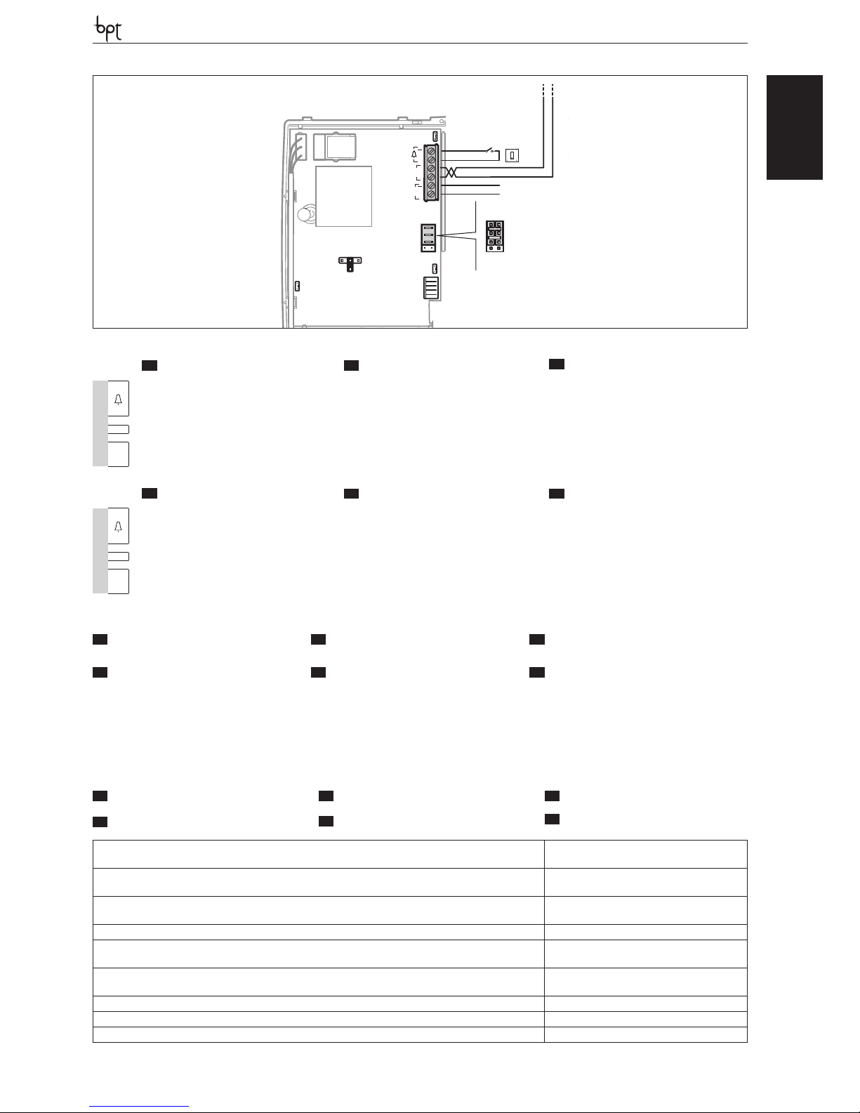
FUNZIONE DEI CONNETTORI
EN
FUNCTION OF CONNECTOR
DE
FUNKTION DER STECKVERBINDER
CN4: collegamento al monitor. CN4: connection to the monitor. CN4: Monitoranschluss.
FR
FONCTION DE CONNECTEUR
ES
FUNCIÓN DE CONECTORE
PT
FUNÇÃO DE CONECTORE
CN4: raccordement au moniteur. CN4: conexión al monitor. CN4: ligação ao monitor.
IT
MORSETTIERE
EN
TERMINAL BOARDS
DE
KLEMMENBRETTER
M1
–
+
Ingresso chiamata dal pianerottolo Doorbell input Rufeingang vom Treppenhaus
B
Ingresso linea BUS BUS line input Eingang BUS-Leitung
–
14÷18 Vcc
alimentazione locale
Power supply local
From 14÷18 V DC
Stromversorgung örtlich
zu 14÷18 VDC
+
Alimentazione locale-Supply voltage local-Stromversorgung örtlichAlimentation local-Alimentación local-Alimentação local
14-18 VDC
Alimentazione da BUS-Power supply from BUS-Stromversorgung über BUS-Alimentation depuis BUSAlimentación desde BUS-Alimentação de BUS
15÷20 VDC
Assorbimento-Absorption-StromaufnahmeAbsorption-Consumo-Consumo
YVL301: 520 mA max (<1 mA stand-by)
Dimensioni-Dimensions-Maße-Dimensions-Dimensiones-Dimensões 206x215x59 mm
Temperatura di stoccaggio-Storage temperature-Lagerungstemperatur
Température de stockage-Temperatura de almacenamiento-Temperatura de armazenagem
-25 °C +70 °C
Temperatura di funzionamento-Operating temperature-Betriebstemperatur
Température de fonctionnement -Temperatura de funcionamiento-Temperatura de funcionamento
0 °C +35 °C
Grado IP-IP Degree-IP-Grad-Degré IP-Grado IP-Grau IP IP 20
Standard video-Standard video-Videostandard-Standard vidéo-Estándar de vídeo-Standard vídeo YVL301: CCIR (EIA)
Monitor-Monitor- Monitor -Monitor-Monitor-Monitor YVL301: CRT 4’’ (10 cm)
IT
CARATTERISTICHE TECNICHE
FR
CARACTÉRISTIQUES TECHNIQUES
EN
TECHNICAL FEATURES
ES
CARACTERÍSTICAS TÉCNICAS
DE
TECHNISCHE MERKMALE
PT
CARACTERÍSTICAS TÉCNICAS
Page 8
OPHERALYNEA BASIC LYNEA NOVA MITHO VAS/100.30
DVC/01
DVC/01 ME
LYNEABASIC
a
YKT/F
8
IT
ACCESSORI
EN
ACCESSORIES
DE
ZUBEHÖR
a Supporto da tavolo YKT/F a Table-top mounting YKT/F a Tischmontagehalter YKT/F
FR
ACCESSOIRES
ES
ACCESORIOS
PT
ACESSÓRIOS
a Support de table YKT/F a Soporte de sobremesa
YKT/F
a Suporte de mesa YKT/F
IT
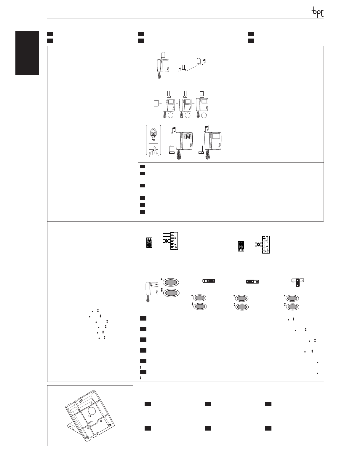
SELEZIONI
EN
SELECTIONS
DE
WAHLEN
FR
SÉLECTIONS
ES
SELECCIONES
PT
SELECÇÕES
SW1 (Attenuazione della chiamata)
SW1 (Call attenuated)
SW1 (Abschwächung des Anrufs)
SW1(Atténuation de l’appel)
SW1 (Atenuación de la llamada)
SW1(Atenuação da chamada)
SW1
SW1
SW1
SW3(Resistenza di chiusura)
SW3 (Resistive load termination)
SW3 (Schließwiderstand)
SW3 (Résistance de fermeture)
SW3 (Resistencia de cierre)
SW3 (Resistência de fecho)
SW3 SW3 SW3
1 2
3
XDV/304
SW8 (Selezione MASTER/SLAVE)
SW8 (Selezione MASTER/SLAVE)
SW8 (Selezione MASTER/SLAVE)
SW8 (Selezione MASTER/SLAVE)
SW8 (Selezione MASTER/SLAVE)
SW8 (Selezione MASTER/SLAVE)
SW8
MASTER
SLAVE
M/S
M/S
SW8
IT
In caso di chiamata contemporanea, solo sul derivato MASTER verrà attivata la comunicazione audio/video.
EN
In case of simultaneous call, the audio/video communication will be activated on the MASTER extension
only.
DE
Bei einem gleichzeitigen Anruf, wird die Audio-/Videoverbindung nur auf der Innensprechstelle MASTER
aktiviert.
FR
En cas d’appel simultané, la communication audio/vidéo sera activée uniquement sur le poste MASTER.
ES
En caso de llamada simultánea, la comunicación audio/vídeo se activará solo en el derivado MASTER.
PT
No caso de chamada contemporânea, só no derivado MASTER é que será· activada a comunicação áudio/
vídeo.
SW9 (Selezione sorgente di alimentazione)
SW9 (Selects power source)
SW9 (Auswahl der Stromquelle)
SW9 (Sélection source d’alimentation)
SW9 (Selección de fuente de alimentación)
SW9 (Selección de fuente de alimentación)
B
+
+
M1
SW9
LOCAL
BUS
Alimentazione separata
Separate power supply
Getrennte Versorgung
Alimentation séparée
Alimentación separada
Alimentação separada
B
+
M1
SW9
BUS
LOCAL
+
Alimentazione da BUS
Power supply from BUS
Stromversorgung über BUS
Alimentation depuis BUS
Alimentación desde BUS
Alimentação de BUS
SW10 (Funzione tasti e )
SW10 (Operation of and keys)
SW10 (Funktion Tasten und )
SW10 (Fonction touches et )
SW10 (Función botones y )
SW10 (Função das teclas e )
SW10
SW10
SW10
SW10
SW10
SW10
INTERCOM 1
INTERCOM 2
INTERCOM 3
INTERCOM 4
INTERCOM 1
INTERCOM 2
INTERCOM 3
INTERCOM 4
AUX1
AUX2
INTERCOM 1
INTERCOM 2
IT
NOTA. A cornetta agganciata in qualsiasi posizione sia il Jumper SW10 i pulsanti e funzioneranno
come AUX1 e AUX2.
EN
NOTE. With the receiver connected, regardless of the position of Jumper SW10, the and buttons
will operate as AUX1 and AUX2.
DE
HINWEIS Mit eingehängtem Hörer funktionieren der Verbindungsdraht SW10 und die Taste e als
AUX1 und AUX2.
FR
NOTE. À combiné raccroché quelle que soit la position, soit le Jumper SW10, la touche et fon-
ctionneront comme AUX1 et AUX2.
ES
NOTA. Con el auricular colgado en cualquier posición, tanto el Jumper SW10 como los botones y
funcionarán como AUX1 y AUX2.
PT
NOTA. Com o auscultador encaixado em qualquer posição, quer o Jumper SW10, quer o botão e
funcionam como AUX1 e AUX2.
Page 9
OPHERA LYNEA BASICLYNEANOVAMITHOVAS/100.30
DVC/01
DVC/01 ME
LYNEABASIC
9
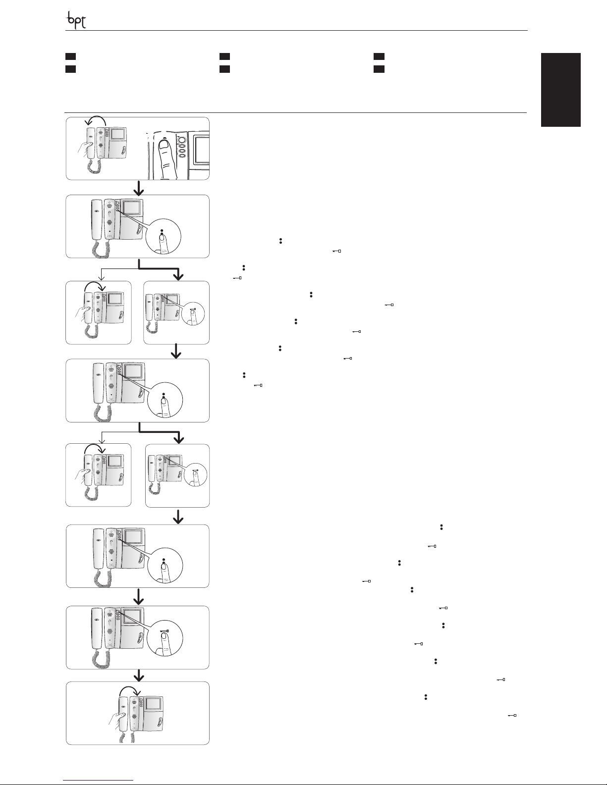
Ingresso in Programmazione. S ollevare la cornetta e premere per 5 volte il pulsante A entro 5 s. Un breve segnale acustico conferma l’in-
gresso in programmazione a.
Accessing programming. Lift the receiver and press the button A 5 times within 5 s. A brief acoustic signal will con rm that programming has
been accessed a.
Einstieg in die Programmierung. Den Hörer hochheben und innerhalb 5 Sek. fünf,mal die Taste A drücken. Ein kurzer Signalton bestätigt
den Einstieg in die Programmierung a.
Entrée en Programmation. D écrocher le combiné et appuyer 5 fois sur la touche A dans les 5 s. Un bref signal sonore con rme l’entrée dans la
programmation a.
Entrada en la modalidad de Programación Descuelgue el auricular y pulse 5 veces el botón A antes de 5 s. Una breve señal acústica
con rmará que se ha entrado en la modalidad de programación a.
Entrada em Programação. Levante o auscultador e aper te 5 vezes o botão A por 5 s. Um breve sinal acústico con rmará a entrada em programação a.
Programmazione della melodia associata alla chiamata dal posto esterno (1 segnale acustico). Per ascoltare in sequenza le
melodie premere il tasto
b. Per selezionare la melodia ed uscire dalla programmazione riporre la cornetta c. Per selezionare la melodia e
proseguire con la programmazione premere il tasto d.
Programming the melody associated to the call from the entry panel (1 acoustic signal). To hear the melodies in sequence, press
the key b. To select the melody and exit programming, replace the receiver c. To select the melody and continue with programming, press the
key d.
Programmierung der Melodie, die mit dem Anruf von der Außenstation verknüpft ist (1 akustisches Signal). Um die Melodien nacheinander zu hören, die Taste drücken b. Zum Wählen der Melodie und Verlassen der Programmierung, den Hörer wieder aufl egen
c. Zum Wählen der Melodie und fortsetzen der Programmierung, die Taste drücken d.
Programmation de la mélodie associée à l’appel provenant du poste extérieur (1 signal sonore). Pour écouter les mélodies en
séquence, appuyer sur la touche b. Pour sélectionner la mélodie et quitter la programmation, raccrocher le combiné c. Pour sélectionner la
mélodie et continuer la programmation, appuyer sur la touche d.
Programación de la melodía asociada a la llamada desde la placa exterior (1 señal acústica). Para escuchar en secuencia las
melodías, pulse el botón b. Para seleccionar la melodía y salir de la modalidad de programación, cuelgue el auricular c. Para seleccionar la
melodía y proseguir con la programación, pulse el botón d.
Programação da melodia associada à chamada da placa botoneira (1 sinal acústico). Para ouvir as melodias em sequência aperte
a tecla b. Para seleccionar a melodia e sair da programação, pouse o auscultador c. Para seleccionar a melodia e continuar a programação,
aperte a tecla d.
Programmazione della melodia associata alla chiamata dal pianerottolo (2 segnali acustici). Per questo tipo di programmazione e f g procedere come la “Programmazione della melodia associata alla chiamata dal posto esterno” precedentemente descritta.
Programming the melody associated with the doorbell (2 acoustic signals). For this type of programming e f g proceed as
previously described for “Programming the melody associated to the call from the entry panel”.
Programmierung der Melodie, die mit dem Anruf vom Treppenhaus verknüpft ist (2 akustische Signale). Für diese Programmierungsart e f g wie bei der zuvor beschriebenen “Programmierung der Melodie, die mit dem Anruf von der Außenstation verknüpft
ist” vorgehen.
Programmation de la mélodie associée à l’appel provenant du palier (2 signaux sonores). Pour ce type de programmation e f
g procéder comme pour la “Programmation de la mélodie associée à l’appel provenant du poste extérieur” décrite précédemment.
Programación de la melodía asociada a la llamada desde el rellano (2 señales acústicas). Para este tipo de programación
e f g siga los mismos pasos que para la “Programación de la melodía asociada a la llamada desde la placa exterior” descrita previamente.
Programação da melodia associada à chamada do patamar (2 sinais acústicos). Para este tipo de programação e f g continue
como para a “Programação da melodia associada à chamada da placa botoneira” descrita anteriormente.
Programmazione del numero di squilli di chiamata (3 segnali acustici). Premere il tasto tante volte quanti sono gli squilli che si
è scelto per la chiamata (da 1 a 6 squilli) h. Dopo 3 s dall’ultima pressione del tasto verrà riprodotta la chiamata selezionata per il numero di squilli
prescelto. Per salvare le impostazioni riporre la cornetta j altrimenti premere il pulsante apriporta i per ritornare nuovamente alla programmazione della melodia di chiamata dal posto esterno.
Programming the number of call rings (3 acoustic signals). Press the key the number of times equal to the rings selected for the call (1
to 6 rings) h. 3 s after the key is pressed the last time, the call selected for the selected number of rings will be will be reproduced. To save the new
setting, hang up j; otherwise, press the door lock release button ( ) i to enter the entry panel call melody programming procedure again.
Programmierung der Anzahl der Ruftöne (3 akustische Signale). Die Taste so oft drücken, wie Ruftöne für den Anruf gewünscht
werden (1 bis 6 Ruftöne) h. 3 s nach dem letzten Drücken der Taste wird der gewählte Anruf mit der Anzahl der festgelegten Ruftöne wiederholt.
Zur Speicherung dieser Neueinstellung j Hörer wieder aufl egen. Andernfalls Türöff nertaste drücken ( ) i, um erneut auf die Programmierung der Melodie des Anrufs von der Außenstation überzugehen.
Programmation du nombre de sonneries d’appel (3 signaux sonores). Appuyer sur la touche autant de fois que le nombre de sonne-
ries que l’on a choisi pour l’appel (de 1 à 6 sonneries) h. 3 s après la dernière pression sur la touche, l’appel sélectionné pour le nombre de sonneries
choisi sera e ectué. Pour enregistrer raccrocher j; sinon, appuyer sur la touche ouvre-porte ( ) i pour accéder de nouveau à la programmation
de la mélodie d’appel depuis le poste extérieur.
Programación del número de tonos de llamada (3 señales acústicas). Pulse el botón un número de veces igual a los tonos que
se desean para la llamada (de 1 a 6 tonos) h. Pasados 3 s desde la última vez que se pulse el botón, se reproducirá la llamada seleccionada con
el número de tonos elegido. Para memorizar la nueva con guración basta colgar el auricular j, sino pulsar el botón abrepuerta ( ) i para
acceder de nuevo a la programación de la melodía de llamada desde la placa exterior.
Programação do número de toques de chamada (3 sinais acústicos). Aperte a tecla tantas vezes quantas desejar para o número de
toques da chamada (de 1 a 6 toques) h. Após 3 s, a partir da última vez que apertou a tecla, será reproduzida a chamada seleccionada para o
número de toques desejado. Para salvar a nova regulação pousar o auscultador j, diferentemente premir o botão de abertura da porta ( ) i
para ter acesso novamente à programação da melodia de chamada da placa botoneira.
y Per la programmazione della chiamata, vedere la docu�
mentazione dei posti esterni.
y For call programming, see the entry panel documentation.
y Für die Rufprogrammierung, siehe Unterlagen der Außen�
stationen.
y Pour la programmation de l’appel, voir la documentation
des postes extérieurs.
y Para la programación de la llamada, consulte la documen�
tación de las placas exteriores.
y Para programar a chamada, consulte a documentação das
placas botoneiras.
IT
PROGRAMMAZIONE
EN
PROGRAMMING
DE
PROGRAMMIERUNG
FR
PROGRAMMATION
ES
PROGRAMACIÓN
PT
PROGRAMAÇÃO
b
c
d
h
i
e
f
j
g
a
A
X 5
beep
+
Page 10
LYNEA
OPHERALYNEA BASIC LYNEA NOVA MITHO VAS/100.30
DVC/01
DVC/01 ME
LYNEA YVYVC
IT
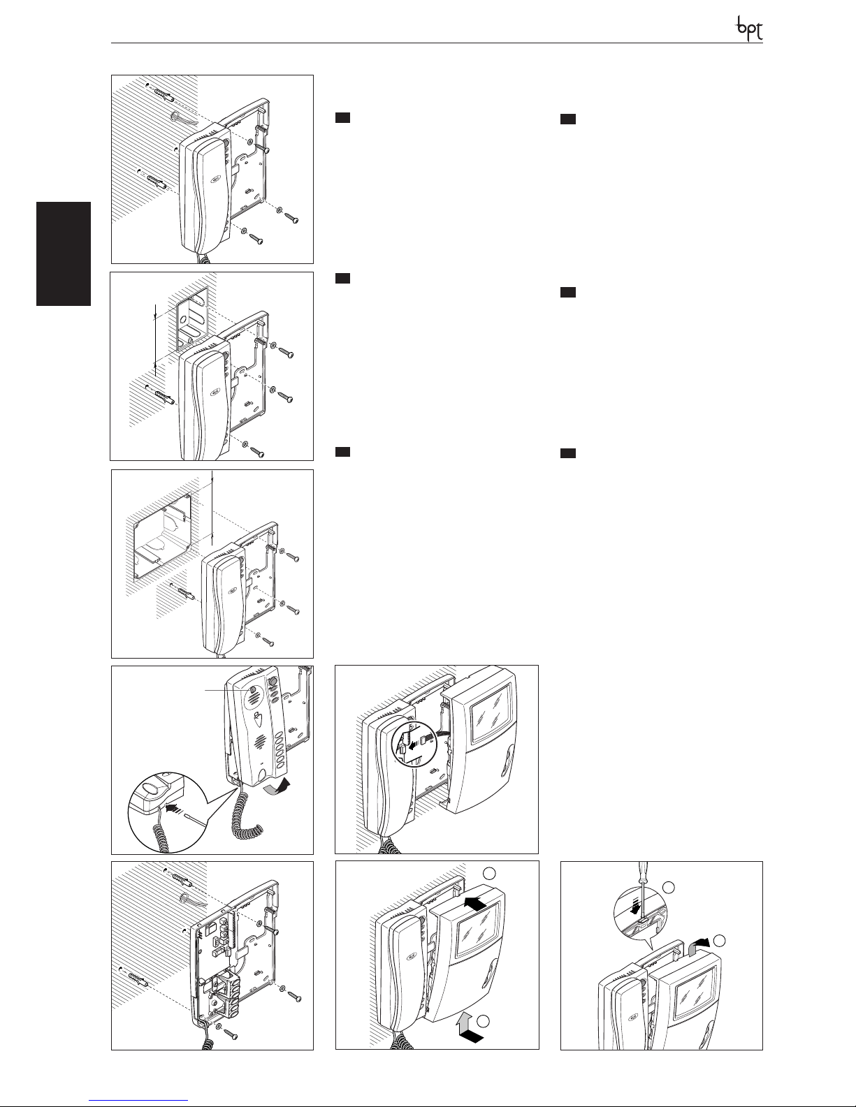
INSTALLAZIONE
ATTENZIONE. Si raccomanda di installare il
monitor in ambiente asciutto.
Il supporto da parete può essere installato seguendo le indicazioni delle fig. 1÷5.
Montare il modulo monitor sul supporto da parete come indicato nelle figure 6 e 7.
Per togliere il modulo monitor agire con cacciavite attraverso la feritoia sul mobile (fig. 8).
Per rimuovere il mobile YKP, agire con un cacciavite attraverso l’apposita feritoia (fig. 4).
EN
INSTALLATION
WARNING. It is recommended to install the
monitor in a dry place.
The wall mounting can be installed following the
instructions in figures 1-5.
Fit the monitor module on the wall mounting as
illustrated in figures 6 and 7.
To remove the monitor module, prise it off by
inserting a screwdriver in the slot in the housing
(fig. 8).
To remove the YKP cover, use a screwdriver inserted in the slot (fig. 4).
DE
INSTALLATION
ACHTUNG. Es wird empfohlen den Monitor
an einer geschützten Stelle zu installieren.
Die Wandhalterung kann gemäß nachstehenden Abb. 1÷5 erfolgen.
Monitormodul auf den Wandhalter positionieren
und dabei den Abb. 6 und 7 entsprechend vorgehen.
Bei der Abnahme des Monitormoduls mit einem
Schraubenzieher im Gehäuseschlitz einwirken
(Abb. 8).
Zum Entfernen des Deckels YKP, einen Schraubenzieher in den entsprechenden Schlitz stecken (Abb. 4).
FR
INSTALLATION
ATTENTION. Le moniteur doit être installé
dans une pièce séche.
Le support mural peut être installé en suivant les
instructions des figures 1÷5. Monter le module
moniteur sur le support mural comme indiqué
aux figures 6 et 7. Pour ôter le module moniteur,
passer un tournevis à travers la fente sur le meuble (fig. 8).
Pour enlever le couvercle YKP, agir avec un
tournevis à travers la fente prévue à cet effet (fig.
4).
ES
INSTALACIÓN
ATENCION. Se recomienda instalar el monitor en un ambiente seco.
El soporte mural se puede instalar siguiendo las
indicaciones de las fig. 1÷5. Montar el módulo
monitor en el soporte mural como mostrado en
las figuras 6 y 7.
Para quitar el módulo monitor actuar con un destornillador a través de la ranura en la caja (fig. 8).
Para retirar la tapa YKP, utilice un destornillador a
través de la rejilla correspondiente (fig. 4).
PT
INSTALAÇÃO
ATENÇÃO. Se aconselha de instalar o monitor
em ambiente enxuto.
O suporte de parede pode ser instalado seguindo as indicações das fig. 1÷5. Montar o
módulo monitor no suporte de parede como
indicado nas figuras 6 e 7.
Para tirar o módulo monitor agir com chave de
parafuso através da abertura do móvel (fig. 8).
Para remover a tampa YKP, agir com uma chave
através da fenda apropriada (fig. 4).
83,5 mm
2
1
5
A
4
95 mm
3
6
PHI
1
2
8
1
2
7
503
10
Page 11
LYNEA
OPHERA LYNEA BASICLYNEANOVAMITHOVAS/100.30
DVC/01
DVC/01 ME
SW9
BUS
LOCAL
14-18VDC
SW3
SW8
SW1
CN4
BUS
SW9
B
+
+
M1
LOCAL
M2
CN1BACN2
CN3
A/B
IT
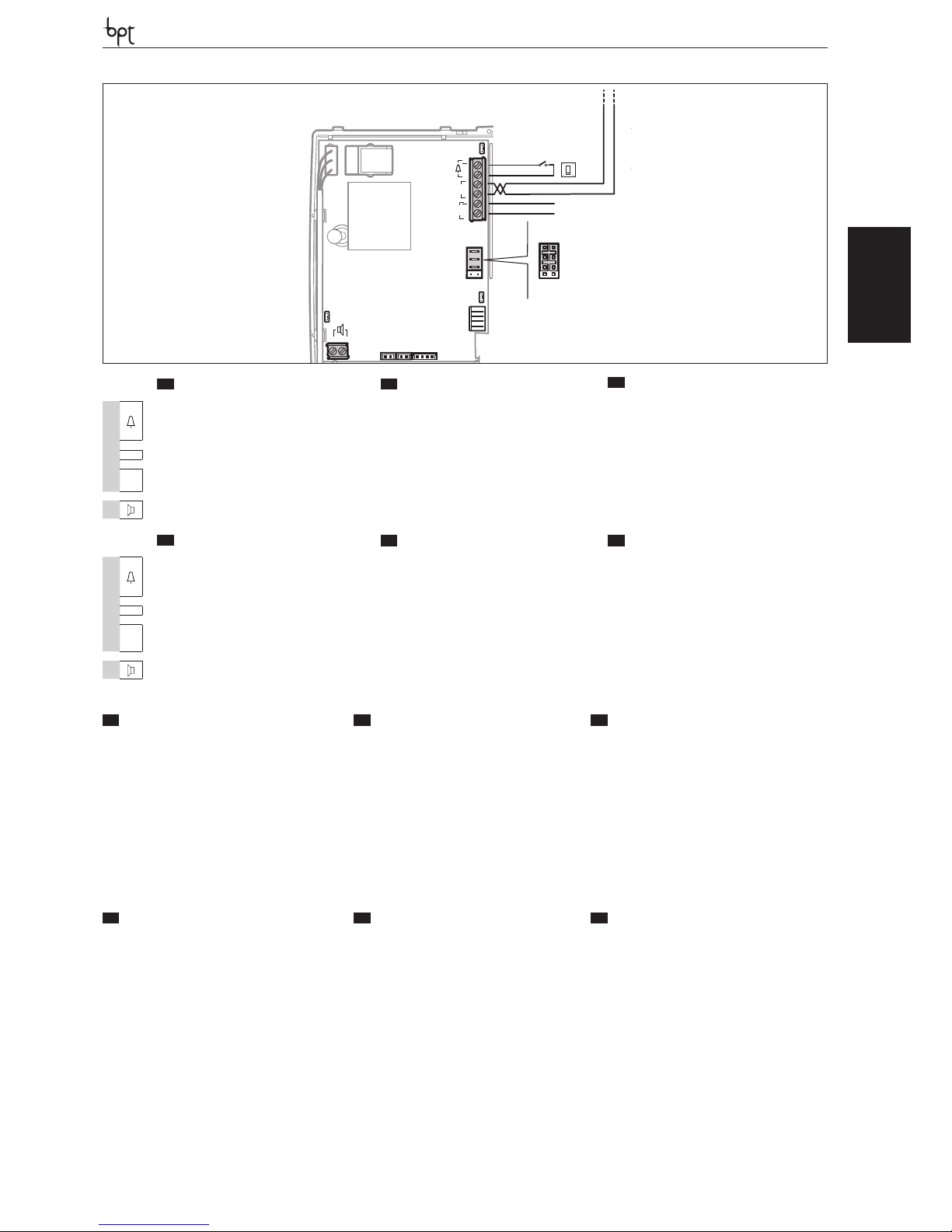
FUNZIONE DEI CONNETTORI
EN
FUNCTION OF CONNECTORS
DE
FUNKTION DER STECKVERBINDER
CN1 collegando a questo connettore l’accessorio
YP3 vengono aggiunti 3 tasti per chiamate intercomunicanti (1-3) o 3 comandi ausiliari aggiuntivi
(3-5).
CN1 when the accessory YP3 is connected to
this connector, 3 keys are added for intercom
calls (1-3) or 3 additional auxiliary controls (3-5).
CN1 wenn man das Zubehör YP3 an diesen
Steckverbinder anschließt, erhält man 3 weitere
Tasten für Intercom-Anrufe (1-3) oder 3 Zusatzsteuerungen (3-5).
CN2 collegando a questo connettore l’accessorio
YP3 vengono aggiunti ulteriori 3 tasti per chiamate
intercomunicanti (4-6) o 3 comandi ausiliari aggiuntivi (6-8).
CN2 when the accessory YP3 is connected to
this connector, 3 additional keys are added for
intercom calls (4-6) or 3 additional auxiliary controls (6-8).
CN2 wenn man das Zubehör YP3 an diesen
Steckverbinder anschließt, erhält man 3 weitere
Tasten für Intercom-Anrufe (4-6) oder 3 Zusatzsteuerungen (6-8).
CN3 collegamento all’accessorio YPL CN3 connection to the accessory YPL CN3 Anschluss an Zubehör YPL
CN4: collegamento al monitor YV- YVC CN4: connection to the monitor YV- YVC CN4: Anschluss an Monitor YV- YVC
FR
FONCTION DES CONNECTEURS
ES
FUNCIÓN DE LOS CONECTORES
PT
FUNÇÃO DOS CONECTORES
CN1 en raccordant à ce connecteur l’accessoire YP3,
on ajoute 3 touches pour des appels à intercommunication (1-3) ou 3 commandes auxiliaires supplémentaires (3-5).
CN1 conectando a este conector el accesorio
YP3 se añaden 3 botones para llamadas intercomunicantes (1-3) o 3 mandos auxiliares adicionales (3-5).
CN1 ao ligar o acessório YP3 a este conector,
serão adicionadas 3 teclas para chamadas intercomunicantes (1-3) ou 3 comandos auxiliares
adicionais (3-5).
CN2 en raccordant à ce connecteur l’accessoire YP3,
on ajoute 3 touches pour des appels à intercommunication (4-6) ou 3 commandes auxiliaires supplémentaires (6-8).
CN2 conectando a este conector el accesorio
YP3 se añaden otros 3 botones para llamadas
intercomunicantes (4-6) o 3 mandos auxiliares
adicionales (6-8).
CN2 ao ligar o acessório YP3 a este conector,
serão adicionadas outras 3 teclas para chamadas
intercomunicantes (4-6) ou 3 comandos auxiliares adicionais (6-8).
CN3 connexion d’accessoires YPL CN3 conexión de accesorios YPL CN3 conexão de acessórios YPL
CN4: raccordement au moniteur YV- YVC CN4: conexión al monitor YV- YVC CN4: ligação ao monitor YV- YVC
IT
MORSETTIERE
EN
TERMINAL BOARDS
DE
KLEMMENBRETTER
M1
–
+
Chiamata pianerottolo Doorbell Ruf vom Treppenhaus
B
Ingresso linea BUS BUS line input Eingang BUS-Leitung
–
da 14÷18 Vcc
alimentazione locale
Power supply local
From 14÷18 V DC
Stromversorgung örtlich
zu 14÷18 VDC
+
M2
collegamento per l’altoparlante YAL connection for YAL loudspeake raccordement pour le haut-parleur YAL
FR
BORNIERS
ES
BORNERAS
PT
RÉGUAS DE BORNES
M1
–
+
Appel depuis le palier Llamada desde el rellano Chamada do patamar
B
Entrée ligne BUS Entrada línea BUS Entrada linha BUS
–
Alimentation local
de 14÷18 Vcc
Alimentación local
de 14÷18 Vcc
Alimentação local
desde 14÷18 Vcc
+
M2
conexión para el altavoz YAL conexión para el altavoz YAL ligação para o altifalante YAL
11
Page 12
LYNEA
OPHERALYNEA BASIC LYNEA NOVA MITHO VAS/100.30
DVC/01
DVC/01 ME
17
5
21
7
7A
7
12
13
14
15
16
YP3
YKT/F
YPL
YAL
a
db
c
IT
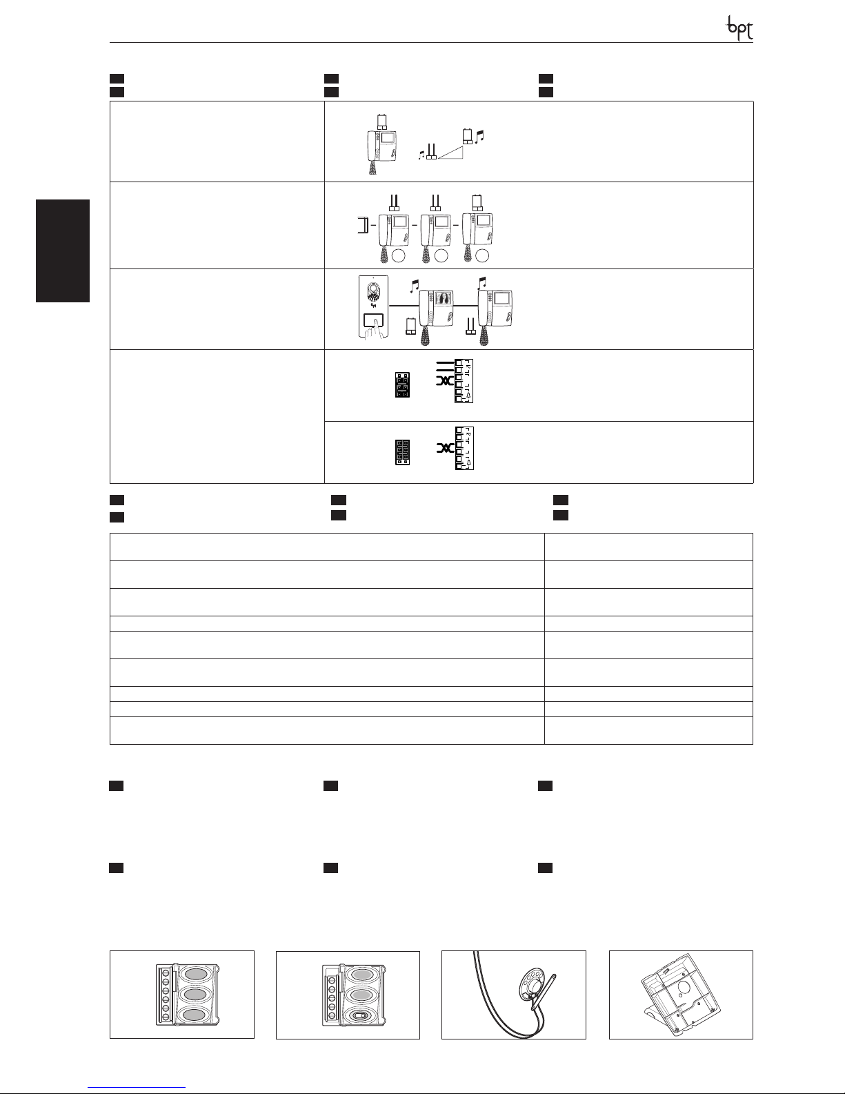
SELEZIONI
EN
SELECTIONS
DE
WAHLEN
FR
SÉLECTIONS
ES
SELECCIONES
PT
SELECÇÕES
SW1 (Attenuazione della chiamata)
SW1 (Call attenuated)
SW1 (Abschwächung des Anrufs)
SW1(Atténuation de l’appel)
SW1 (Atenuación de la llamada)
SW1(Atenuação da chamada)
SW1
SW1
SW1
SW3(Resistenza di chiusura)
SW3 (Resistive load termination)
SW3 (Schließwiderstand)
SW3 (Résistance de fermeture)
SW3 (Resistencia de cierre)
SW3 (Resistência de fecho)
SW3 SW3 SW3
1 2
3
XDV/304
SW8 Selezione MASTER/SLAVE
SW8 MASTER/SLAVE Selects
SW8 Auswahl MASTER/SLAVE
SW8 Sélection MASTER/SLAVE
SW8 Selección MASTER/SLAVE
SW8 Selección MASTER/SLAVE
SW8
MASTER
SLAVE
M/S
M/S
SW8
SW9 (Selezione sorgente di alimentazione)
SW9 (Selects power source)
SW9 (Auswahl der Stromquelle)
SW9 (Sélection source d’alimentation)
SW9 (Selección de fuente de alimentación)
SW9 (Selección de fuente de alimentación)
B
+
M1
SW9
LOCAL
BUS
Alimentazione separata - Separate power supply
Getrennte Versorgung - Alimentation séparée
Alimentación separada - Alimentação separada
B
+
M1
SW9
BUS
LOCAL
Alimentazione da BUS - Power supply from BUS
Stromversorgung über BUS - Alimentation depuis BUS
Alimentación desde BUS - Alimentação de BUS
12
Alimentazione locale-Supply voltage local-Stromversorgung örtlichAlimentation local-Alimentación local-Alimentação local
14-18 VDC
Alimentazione da BUS-Power supply from BUS-Stromversorgung über BUSAlimentation depuis BUS-Alimentación desde BUS-Alimentação de BUS
15÷20 VDC
Assorbimento-Absorption-Stromaufnahme-Absorption-Consumo-Consumo YV: 520 mA max (<1 mA stand-by)
YVC: 220 mA max (<1 mA stand-by)
Dimensioni-Dimensions-Maße-Dimensions-Dimensiones-Dimensões 206x215x59 mm
Temperatura di stoccaggio-Storage temperature-Lagerungstemperatur
Température de stockage-Temperatura de almacenamiento-Temperatura de armazenagem
-25°C +70 °C
Temperatura di funzionamento-Operating temperature-Betriebstemperatur
Température de fonctionnement -Temperatura de funcionamiento-Temperatura de funcionamento
0 °C +35 °C
Grado IP-IP Degree-IP-Grad-Degré IP-Grado IP-Grau IP IP 20
Standard video-Standard video-Videostandard-Standard vidéo-Estándar de vídeo-Standard vídeo YV: CCIR (EIA) YVC: PAL
Monitor-Monitor-Monitor-Monitor-Monitor-Monitor YV: CRT 4’’ (10 cm)
YVC: LCD TFT 3,5’’ 4:3
IT
ACCESSORI
EN
ACCESSORIES
DE
ZUBEHÖR
a Espansione di chiamata a 3 pulsanti YP3;
b Modulo attenuazione di chiamata con segnala-
zione luminosa YPL;
c Altoparlante supplementare YAL;
d Supporto da tavolo YKT/F;
a 3-button call expansion YP3;
b Ring tone decrease module with indicator light
YPL;
c Additional loudspeaker YAL.
d Table-top mounting YKT/F;
a Ruferweiterung mit 3 tasten YP3;
b Modul zur Rufabschwächung mit Leuchtanzei-
ge YPL;
c Zusätzlicher lautsprecher YAL.
d Tischmontagehalter YKT/F
FR
ACCESSOIRES
ES
ACCESORIOS
PT
ACESSÓRIOS
a Expansion d’appel à 3 boutons-poussoirs YP3;
b Module atténuation d’appel avec voyant lumi-
neux YPL;
c Haut-parleur supplémentaire YAL.
d Support de table YKT/F
a Expansión de llamada con 3 pulsadores YP3;
b Módulo de atenuación de llamada con indica-Módulo de atenuación de llamada con indica-
ción luminosa YPL;
c Altavoz suplementario YAL.
d Soporte de sobremesa YKT/F;
a Expansão de chamada de 3 botões YP3;
b Modulo de atenuação de chamada com sinali-Modulo de atenuação de chamada com sinali-
zação luminosa YPL;
c Altifalante suplementar YAL.
d Suporte de mesa YKT/F;
IT
CARATTERISTICHE TECNICHE
FR
CARACTÉRISTIQUES TECHNIQUES
EN
TECHNICAL FEATURES
ES
CARACTERÍSTICAS TÉCNICAS
DE
TECHNISCHE MERKMALE
PT
CARACTERÍSTICAS TÉCNICAS
Page 13
LYNEA
OPHERA LYNEA BASICLYNEANOVAMITHOVAS/100.30
DVC/01
DVC/01 ME
13
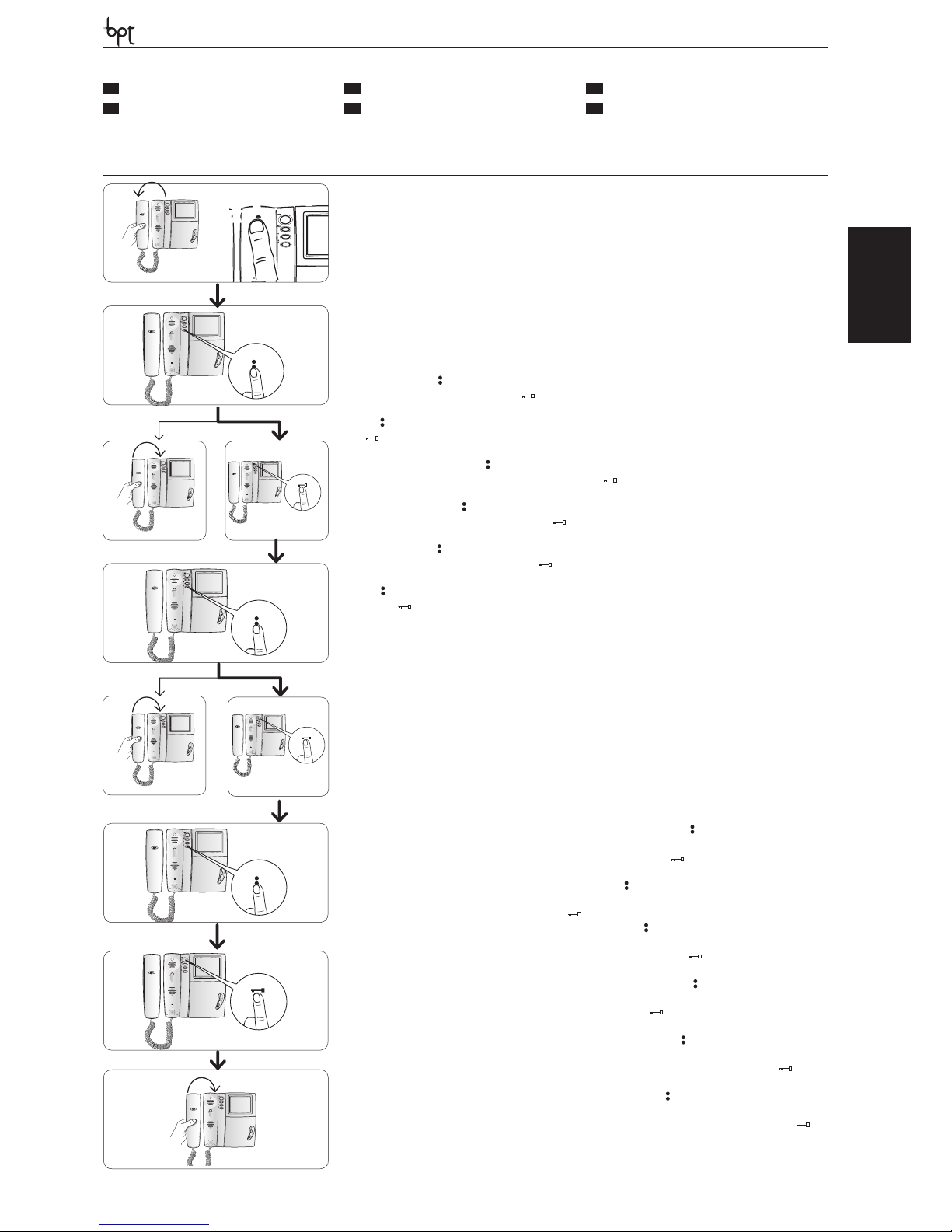
Ingresso in Programmazione. S ollevare la cornetta e premere per 5 volte il pulsante A entro 5 s. Un breve segnale acustico conferma l’in-
gresso in programmazione a.
Accessing programming. Lift the receiver and press the button A 5 times within 5 s. A brief acoustic signal will con rm that programming has
been accessed a.
Einstieg in die Programmierung. Den Hörer hochheben und innerhalb 5 Sek. fünf,mal die Taste A drücken. Ein kurzer Signalton bestätigt
den Einstieg in die Programmierung a.
Entrée en Programmation. D écrocher le combiné et appuyer 5 fois sur la touche A dans les 5 s. Un bref signal sonore con rme l’entrée dans la
programmation a.
Entrada en la modalidad de Programación Descuelgue el auricular y pulse 5 veces el botón A antes de 5 s. Una breve señal acústica
con rmará que se ha entrado en la modalidad de programación a.
Entrada em Programação. Levante o auscultador e aper te 5 vezes o botão A por 5 s. Um breve sinal acústico con rmará a entrada em programação a.
Programmazione della melodia associata alla chiamata dal posto esterno (1 segnale acustico). Per ascoltare in sequenza le
melodie premere il tasto
b. Per selezionare la melodia ed uscire dalla programmazione riporre la cornetta c. Per selezionare la melodia e
proseguire con la programmazione premere il tasto d.
Programming the melody associated to the call from the entry panel (1 acoustic signal). To hear the melodies in sequence, press
the key b. To select the melody and exit programming, replace the receiver c. To select the melody and continue with programming, press the
key d.
Programmierung der Melodie, die mit dem Anruf von der Außenstation verknüpft ist (1 akustisches Signal). Um die Melodien nacheinander zu hören, die Taste drücken b. Zum Wählen der Melodie und Verlassen der Programmierung, den Hörer wieder aufl egen
c. Zum Wählen der Melodie und fortsetzen der Programmierung, die Taste drücken d.
Programmation de la mélodie associée à l’appel provenant du poste extérieur (1 signal sonore). Pour écouter les mélodies en
séquence, appuyer sur la touche b. Pour sélectionner la mélodie et quitter la programmation, raccrocher le combiné c. Pour sélectionner la
mélodie et continuer la programmation, appuyer sur la touche d.
Programación de la melodía asociada a la llamada desde la placa exterior (1 señal acústica). Para escuchar en secuencia las
melodías, pulse el botón b. Para seleccionar la melodía y salir de la modalidad de programación, cuelgue el auricular c. Para seleccionar la
melodía y proseguir con la programación, pulse el botón d.
Programação da melodia associada à chamada da placa botoneira (1 sinal acústico). Para ouvir as melodias em sequência aperte
a tecla b. Para seleccionar a melodia e sair da programação, pouse o auscultador c. Para seleccionar a melodia e continuar a programação,
aperte a tecla d.
Programmazione della melodia associata alla chiamata dal pianerottolo (2 segnali acustici). Per questo tipo di programmazione e f g procedere come la “Programmazione della melodia associata alla chiamata dal posto esterno” precedentemente descritta.
Programming the melody associated with the doorbell (2 acoustic signals). For this type of programming e f g proceed as
previously described for “Programming the melody associated to the call from the entry panel”.
Programmierung der Melodie, die mit dem Anruf vom Treppenhaus verknüpft ist (2 akustische Signale). Für diese Programmierungsart e f g wie bei der zuvor beschriebenen “Programmierung der Melodie, die mit dem Anruf von der Außenstation verknüpft
ist” vorgehen.
Programmation de la mélodie associée à l’appel provenant du palier (2 signaux sonores). Pour ce type de programmation e f
g procéder comme pour la “Programmation de la mélodie associée à l’appel provenant du poste extérieur” décrite précédemment.
Programación de la melodía asociada a la llamada desde el rellano (2 señales acústicas). Para este tipo de programación
e f g siga los mismos pasos que para la “Programación de la melodía asociada a la llamada desde la placa exterior” descrita previamente.
Programação da melodia associada à chamada do patamar (2 sinais acústicos). Para este tipo de programação e f g continue
como para a “Programação da melodia associada à chamada da placa botoneira” descrita anteriormente.
Programmazione del numero di squilli di chiamata (3 segnali acustici). Premere il tasto tante volte quanti sono gli squilli che si
è scelto per la chiamata (da 1 a 6 squilli) h. Dopo 3 s dall’ultima pressione del tasto verrà riprodotta la chiamata selezionata per il numero di squilli
prescelto. Per salvare le impostazioni riporre la cornetta j altrimenti premere il pulsante apriporta i per ritornare nuovamente alla programmazione della melodia di chiamata dal posto esterno.
Programming the number of call rings (3 acoustic signals). Press the key the number of times equal to the rings selected for the call (1
to 6 rings) h. 3 s after the key is pressed the last time, the call selected for the selected number of rings will be will be reproduced. To save the new
setting, hang up j; otherwise, press the door lock release button ( ) i to enter the entry panel call melody programming procedure again.
Programmierung der Anzahl der Ruftöne (3 akustische Signale). Die Taste so oft drücken, wie Ruftöne für den Anruf gewünscht
werden (1 bis 6 Ruftöne) h. 3 s nach dem letzten Drücken der Taste wird der gewählte Anruf mit der Anzahl der festgelegten Ruftöne wiederholt.
Zur Speicherung dieser Neueinstellung j Hörer wieder aufl egen. Andernfalls Türöff nertaste drücken ( ) i, um erneut auf die Programmierung der Melodie des Anrufs von der Außenstation überzugehen.
Programmation du nombre de sonneries d’appel (3 signaux sonores). Appuyer sur la touche autant de fois que le nombre de sonne-
ries que l’on a choisi pour l’appel (de 1 à 6 sonneries) h. 3 s après la dernière pression sur la touche, l’appel sélectionné pour le nombre de sonneries
choisi sera e ectué. Pour enregistrer raccrocher j; sinon, appuyer sur la touche ouvre-porte ( ) i pour accéder de nouveau à la programmation
de la mélodie d’appel depuis le poste extérieur.
Programación del número de tonos de llamada (3 señales acústicas). Pulse el botón un número de veces igual a los tonos que
se desean para la llamada (de 1 a 6 tonos) h. Pasados 3 s desde la última vez que se pulse el botón, se reproducirá la llamada seleccionada con
el número de tonos elegido. Para memorizar la nueva con guración basta colgar el auricular j, sino pulsar el botón abrepuerta ( ) i para
acceder de nuevo a la programación de la melodía de llamada desde la placa exterior.
Programação do número de toques de chamada (3 sinais acústicos). Aperte a tecla tantas vezes quantas desejar para o número de
toques da chamada (de 1 a 6 toques) h. Após 3 s, a partir da última vez que apertou a tecla, será reproduzida a chamada seleccionada para o
número de toques desejado. Para salvar a nova regulação pousar o auscultador j, diferentemente premir o botão de abertura da porta ( ) i
para ter acesso novamente à programação da melodia de chamada da placa botoneira.
y Per la programmazione della chiamata, vedere la docu�
mentazione dei posti esterni.
y For call programming, see the entry panel documentation.
y Für die Rufprogrammierung, siehe Unterlagen der Außen�
stationen.
y Pour la programmation de l’appel, voir la documentation
des postes extérieurs.
y Para la programación de la llamada, consulte la documen�
tación de las placas exteriores.
y Para programar a chamada, consulte a documentação das
placas botoneiras.
IT
PROGRAMMAZIONE
EN
PROGRAMMING
DE
PROGRAMMIERUNG
FR
PROGRAMMATION
ES
PROGRAMACIÓN
PT
PROGRAMAÇÃO
b
c
d
h
i
e
f
j
g
a
A
X 5
beep
+
Page 14
OPHERA
OPHERALYNEA BASIC LYNEA NOVA MITHO VAS/100.30
DVC/01
DVC/01 ME
IT
INSTALLAZIONE
ATTENZIONE. Si raccomanda di installare il
monitor in ambiente asciutto.
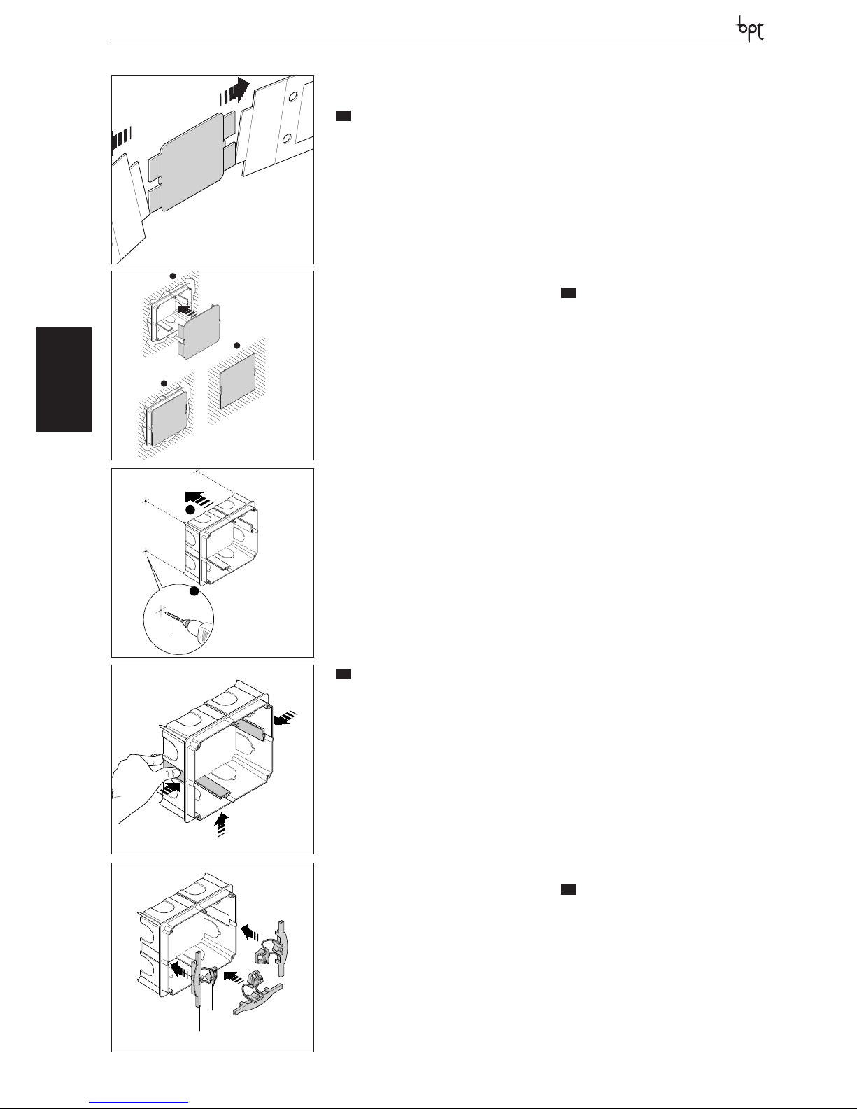
Scatola incasso PHI
La scatola può essere installata sia a muro che
su pareti in cartongesso ad un’altezza adeguata
all’utente rispettando l’indicazione ALTO indicata
sul fondo della scatola d’incasso.
- Dimensioni: 130x114x53,5 mm.
Installazione a muro
La scatola incasso va murata a filo muro munita della protezione in dotazione (fig. 2) ricavata
nell’interno imballo (fig. 1).
Installazione su pareti in cartongesso
Premere la scatola sulla parete per ricavare i 4
punti di riferimento ed effettuare i fori da 10 mm
di diametro (fig. 3).
Tagliare il cartongesso per ricavare il foro di inserimento della scatola.
Eliminare le 3 alette indicate in figura 4.
Inserire nella scatola la parte superiore A dei
morsetti di fissaggio lasciando libera la parte inferiore B (fig. 5).
Introdurre nel foro la scatola incasso e applicare
la parte inferiore B (fig. 6).
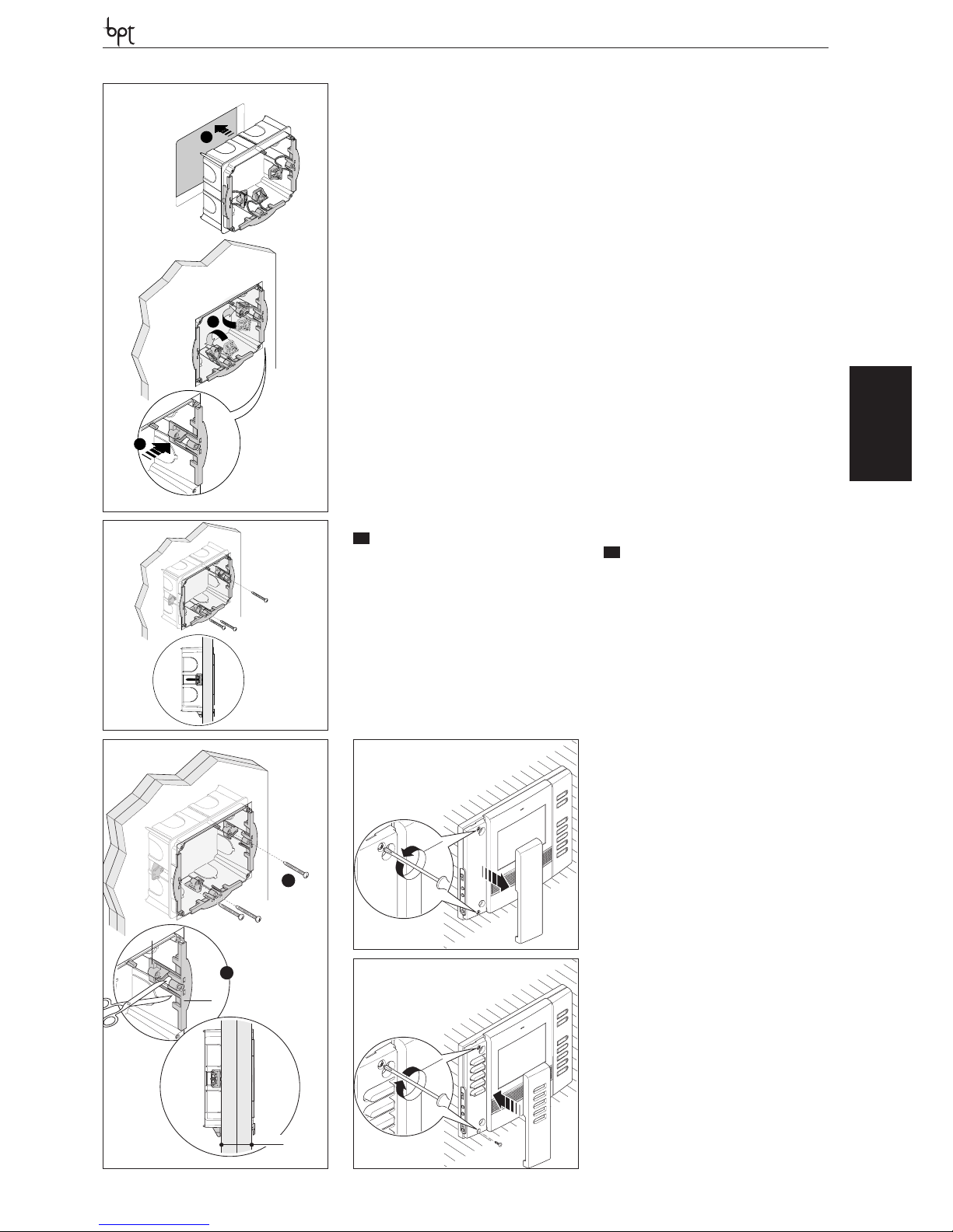
Bloccare la scatola alla parete utilizzando le viti in
dotazione (fig. 7).
Qualora lo spessore della parete sia maggiore di
2 cm è necessario separare le due parti dei morsetti di fissaggio posizionando la parte inferiore B
come indicato in figura 8.
Installazione accessorio intercomunicante
L’accessorio pulsanti in dotazione permette di
trasformare il videocitofono in apparecchio intercomunicante.
Per applicare l’accessorio pulsanti togliere la cover sinistra e svitare le due viti (fig. 9).
Inserire l’accessorio intercomunicante, avvitare le
due viti e inserire la cover (fig. 10).
EN
INSTALLATION
WARNING. It is recommended to install the
monitor in a dry place.
PHI embedding box
The embedding box can be installed in either
masonry or plasterboard walls at a height that is
suitable for the user.
Make sure the UP indication is facing the right way
indicated on the bottom of the embedding box.
- Dimensions: 130x114x53,5 mm.
Masonry wall installation
The embedding box should be installed flush with
the wall, and equipped with the provided protection (fig. 2) to be found in the packaging (fig. 1).
Installation on plasterboard walls
Press the box against the wall to get four reference points where the holes with a 10 mm diameter will be made (fig. 3).
Cut the plasterboard to obtain the hole where
the box will be inserted.
Remove the three tabs as shown in figure 4.
Insert the upper part A of the fastening clamps
into the box, leaving the lower part B free (fig. 5).
Place the embedding box into the hole and then
apply the lower part B (fig. 6).
Secure the box to the wall with the screws provided (fig. 7).
OPHERAOPHERA/B
If the wall is more than 2 cm thick, the two parts
of the fastening clamps will need to be separated, positioning the lower part B as shown in
figure 8.
Installation of intercom accessories
The button accessory provided lets the video
handset change to an intercommunicating appliance.
To apply the button accessory, remove the left
cover and unscrew the two screws (fig. 9).
Insert the intercommunicating accessory, tighten the two screws and insert the cover (fig. 10).
DE
INSTALLATION
ACHTUNG. Es wird empfohlen den Monitor
an einer geschützten Stelle zu installieren.
UP-Kasten PHI
Der UP-Kasten kann mit der beiliegenden
Schutz-vorrichtung und unter Beachtung der
Schrift OBEN, in einer des benutzers angepassten Höhe in die Mauer einbauen die sich auf
dem Boden der UP-Kasten befindet.
- Abmessungen: 130x114x53,5 mm.
Mauerinstallation
Der UP-Kasten wird bündig mit der Wand und
mit der beiliegenden Schutzvorrichtung (Abb.
2) die der internen Verpackung beiliegt (Abb. 1),
gemauert.
Installation in Gipskartonwänden
Der UP-Kasten an die Wand drücken, um die 4
Ansatzpunkte für die Bohrungen mit Durchmesser 10 mm zu erhalten (Abb. 3).
Den Gipskarton zum Einsatz des Gehäuses aufschneiden.
Die 3 in der Abbildung 4 gezeigten Flügel beseitigen. In den oberen Gehäuseteil A die Befestigungsklemmen einsetzen, dabei den unteren
Teil B freilassen (Abb. 5).
Der Up-Kasten in die Öffnung einsetzen und den
unteren Teil B anbringen (Abb. 6).
Mit den beiliegenden Schrauben, der UP-Kasten
an der Wand befestigen (Abb. 7).
Falls die Wandstärke mehr als 2 cm beträgt, müssen die zwei Teile der Befestigungklemmen getrennt und der untere Teil B wie in Abbildung 8
gezeigt, positioniert werden.
Installation Intercom-Zubehör
Den beiliegende Zusatz ermöglicht die Umwandlung des Videosprechgerätes in ein Intercom-Gerät.
Um den Zusatz-Tasten einzubauen, sind die linke
Abdeckung abzunehmen und die zwei Schrauben herauszudrehen (Abb. 9).
Das Intercom-Zubehör einbauen, die zwei
Schrauben eindrehen und die Abdeckung anbringen (Abb. 10).
FR
INSTALLATION
ATTENTION. Le moniteur doit être installé
dans une pièce séche.
Boitîer d’encastrément PHI
Le boîtier peut être installé soit sur le mur que sur
des cloisons en placoplâtre, à une hauteur adéquate
pour l’utilisateur, en respectant l’indication HAUT indiquée sur le fond du boîtier d’encastrement.
- Dimensions: 130x114x53,5 mm.
Installation au mur
Le boîtier à encastrer doit être installé au ras du
1
2
1
3
2
1
10mm
2
Ø
3
4
A
B
5
14
Page 15
OPHERA
OPHERA LYNEA BASICLYNEANOVAMITHOVAS/100.30
DVC/01
DVC/01 ME
mur et muni de la protection en dotation (fig. 2)
comprise dans l’emballage (fig. 1).
Installation sur mur en placoplâtre
Placer le boîtier sur le mur afin de prendre les 4
points de repère pour effectuer les trous de 10
mm de diamètre (fig. 3).
Découper le placoplâtre pour obtenir l’espace
nécessaire à l’installation du boîtier.
Éliminer les 3 ailettes indiquées figure 4.
Insérer la partie supérieure A des étaux de fixation dans le boîtier en laissant libre la partie inférieure B (fig. 5).
Introduire le boîtier dans cet espace et appliquer
la partie inférieure B (fig. 6).
Bloquer le boîtier sur le mur en utilisant les vis en
dotation (fig. 7).
Si l’épaisseur du mur est supérieure à 2 cm, il faut
séparer les deux parties des étaux de fixation, en
positionnant la partie inférieure B comme indiqué figure 8.
Installation de l’accessoire d’intercommunication
L’accessoire à touches fourni permet de transformer le portier vidéo en un appareil à intercommunication.
Pour appliquer l’accessoire à touches enlever le
cache gauche et dévisser les deux vis (fig. 9).
Appliquer l’accessoire à intercommunication,
visser les deux vis et remettre le cache (fig. 10).
ES
INSTALACIÓN
ATENCION. Se recomienda instalar el monitor en un ambiente seco.
Caja de empotrar PHI
La caja puede instalarse tanto en un muro como
en una pared de yeso, a una altura adecuada para
el usuario y respetando la indicación ALTO que se
muestra en el fondo de la caja empotrable.
- Dimensiones:130x114x53,5 mm.
Instalación sobre muro
La caja empotrable se encaja a ras de pared,
equipada con la protección que se entrega con
ella (fig. 2) que se encuentra dentro del embalaje
(fig. 1).
Instalación sobre pared de yeso
Apretar la caja contra la pared para marcar los
cuatro puntos de referencia para efectuar orificios de 10 mm de diámetro (fig. 3).
Cortar el yeso para crear los orificios donde se
introduce la caja.
Eliminar las 3 aletas que se indican en fig. 4.
Introducir en la caja la parte superior (A) de los
bornes de fijación, dejando libre la parte inferior
(B) (fig. 5).
Introducir en el orificio la caja de empotrar y aplicar la parte inferior B (fig. 6).
Fijar la caja a la pared por medio de los tornillos
que se entregan (fig. 7).
Si el espesor de la pared es mayor de 2 cm, es
necesario separar las dos partes de los bornes de
fijación colocando la parte inferior (B) como se
indica en fig. 8.
Instalación de accesorio intercomunicante
El accesorio de botones que se entrega permite
transformar el videoportero en un aparato intercomunicador.
Para aplicar el accesorio de botones, quitar la
cubierta izquierda y desatornillar los dos tornillos
(fig. 9).
Montar el accesorio intercomunicador, atornillar
los dos tornillos y montar la cubierta (fig. 10).
PT
INSTALAÇÃO
ATENÇÃO. Se aconselha de instalar o monitor em ambiente enxuto.
Caixa de encastre PHI
A caixa pode ser instalada tanto na parede como
em painel de gesso acartonado a uma altura
adequada para o utente respeitando a indicação
ALTO indicada no fundo da caixa de encastre.
- Dimensões: 130x114x53,5 mm.
Instalação na parede
A caixa de embutir deve ser murada no fio da parede com a protecção fornecida (fig. 13) contida
na parte interna da embalagem (fig. 12).
Instalação em painéis de gesso acartonado
Apertar a caixa na parede para obter os 4 pontos
de referência para efectuar os furos de 10 mm de
diâmetro (fig. 2).
Cortar o painel de gesso para executar o furo de
introdução da caixa.
Eliminar as 3 abas indicadas na figura 4.
Introduzir na caixa a parte superior A dos bornes
de fixação deixando livre a parte inferior B (fig. 5).
Introduzir no furo a caixa de encastre e aplicar a
parte inferior B (fig. 6).
Bloquear a caixa na parede utilizando os parafusos fornecidos (fig. 7).
Se a espessura da parede for maior de 2 cm é
necessário separar as duas partes dos bornes de
fixação posicionando a parte inferior B como indicado na figura 8.
Instalação do acessório intercomunicante
O acessório botões fornecido permite de transformar o vídeo porteiro em aparelho intercomunicante.
Para aplicar o acessório botões remova a tampa
esquerda e desparafuse os dois parafusos (fig. 9).
Introduza o acessório intercomunicante, aparafuse os dois parafusos e introduza a tampa (fig.
10).
3
2
CLIK!
1
2
1
A
B
>2 cm
OPHERA
1 - 5
2 - 6
3 - 7
OPHERA
2
6
7
8
9
10
15
Page 16
OPHERA
OPHERALYNEA BASIC LYNEA NOVA MITHO VAS/100.30
DVC/01
DVC/01 ME
IT
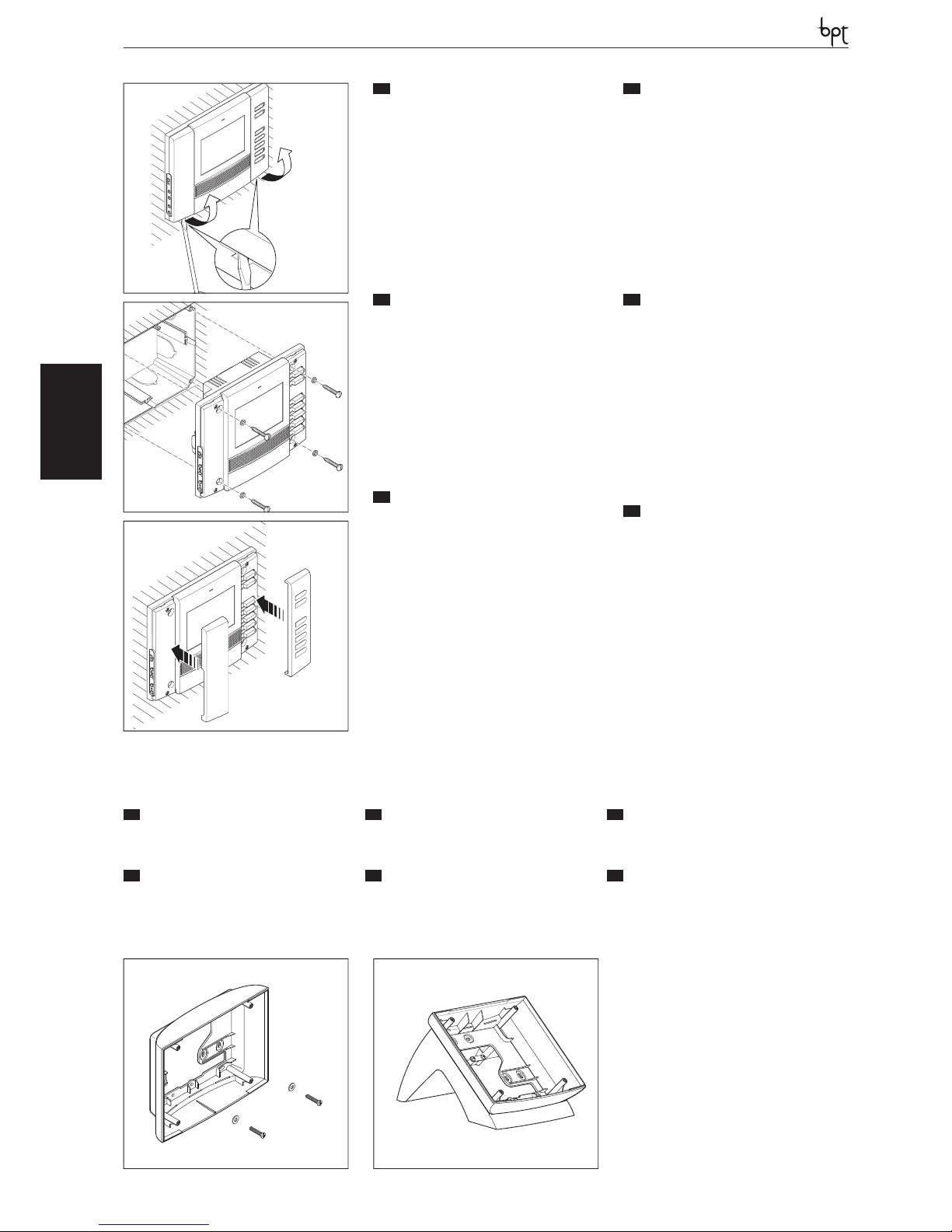
Videocitofono OPHERA e OPHERA/B
Togliere le due cover come indicato in fi gura 11.
Eff ettuare i collegamenti.
Fissare l’apparecchio alla scatola d’incasso utilizzando le viti in dotazione (fi g. 12).
Inserire le cover come indicato in fi gura 13.
Sostituzione delle cover
L’apparecchio viene fornito con 3 set di cover di
diverso colore intercambiabili.
Per la sostituzione agire come indicato in fi gura
11 e 13.
EN
OPHERA and OPHERA/B video handset
Remove the two covers as shown in fi g. 11. Wire
the connections.
Fasten the appliance to the embedding box,
using the screws provided (fi g. 12).
Insert the covers as shown in fi g. 13.
Replace the covers
The appliance is equipped with 3 sets of exchangeable covers in diff erent colours.
To replace, proceed as shown in fi g. 11 and 13.
DE
Videosprechgerät OPHERA und OPHERA/B
Die beiden Abdeckungen, wie in Abb. 11 gezeigt, abnehmen. Anschlüsse vornehmen.
Das Gerät mit den beiliegenden Schrauben am
Einbaugehäuse befestigen (Abb. 12).
Die Abdeckungen einsetzen, siehe Abb. 13.
Auswechseln der Abdeckungen
Das Gerät wird mit 3 auswechselbaren Abdeckungen in unterschiedlichen Farben geliefert.
Für das Auswechseln, wie in Abbildung 11 und
13 gezeigt, vorgehen.
FR
Portier vidéo OPHERA et OPHERA/B
Enlever les deux caches comme indiqué sur fi g.
11. Eff ectuer les raccordements.
Fixer l’appareil au boîtier à encastrer en utilisant
les vis fournies (fi g. 12). Appliquer les caches
comme indiqué sur fi g. 13.
Remplacement des caches
L’appareil est fourni avec 3 sets de cache de diff érente couleur interchangeable.
Pour le remplacement agir comme indiqué sur
les fi gures 11 et 13.
ES
Videoportero OPHERA y OPHERA/B
Quitar las dos cubiertas como se indica en fi g. 11.
Realizar las conexiones. Fijar el aparato a la caja
empotrable usando los tornillos entregados (fi g.
12).
Montar las cubiertas como se indica en fi g. 13.
Sustitución de las cubiertas
El aparato se entrega con 3 juegos de cubiertas
intercambiables de distinto colore.
Para la sustitución, actuar como se indica en fi g.
11 y 13.
PT
Vídeo porteiro OPHERA e OPHERA/B
Remova as duas tampas conforme indicado na
fi g. 11. Efectue as ligações
Fixe o aparelho à caixa de encastre com a utilização dos parafusos fornecidos (fi g. 12).
Introduza a tampa como indicado na fi g. 13.
Substituição das tampas
O aparelho é fornecido com 3 conjuntos de tampas com cores diferentes intercambiáveis.
Para a substituição efectuar quanto indicado na
fi gura 11 e 13.
OPHERA
OPHERA
OPHERA
PHKP
PHKT
a
b
11
12
13
16
IT
ACCESSORI
EN
ACCESSORIES
DE
ZUBEHÖR
a Supporto da parete PHKP;
b Supporto da tavolo PHKT.
a Wall support PHKP;
b PHKT tabletop support.
a Wandhalterung PHKP;
b Tischhalterung PHKT.
FR
ACCESSOIRES
ES
ACCESORIOS
PT
ACESSÓRIOS
a Support mural PHKP;
b Support de table PHKT.
a Soporte de pared PHKP;
b Soporte de mesa PHKT.
a Suporte de parede PHKP;
b Suporte de mesa PHKT.
Page 17
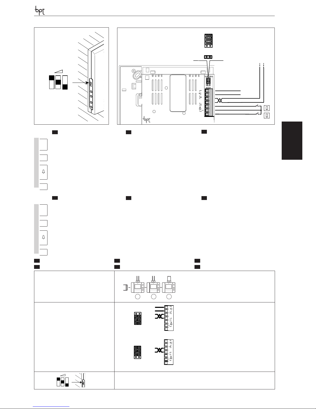
OPHERA
OPHERA LYNEA BASICLYNEANOVAMITHOVAS/100.30
DVC/01
DVC/01 ME
M1M1
SW2
SW1
BUS
LOCAL
B
AL
+
M1
12-16VAC
14-18VDC
OPHERA
A
OPHERA
A
17
IT
SELEZIONI
EN
SELECTIONS
DE
WAHLEN
FR
SÉLECTIONS
ES
SELECCIONES
PT
SELECÇÕES
SW1(Resistenza di chiusura)
SW1 (Resistive load termination)
SW1 (Schließwiderstand)
SW1 (Résistance de fermeture)
SW1 (Resistencia de cierre)
SW1 (Resistência de fecho)
SW1 SW1 SW1
1 2
3
XDV/304
SW2 (Selezione sorgente di alimentazione)
SW2 (Selects power source)
SW2 (Auswahl der Stromquelle)
SW2 (Sélection source d’alimentation)
SW2(Selección de fuente de alimentación)
SW2(Selección de fuente de alimentación)
B
AL
+
M1
SW2
LOCAL
BUS
Alimentazione separata
Separate power supply
Getrennte Versorgung
Alimentation séparée
Alimentación separada
Alimentação separada
B
AL
+
M1
SW2
BUS
LOCAL
Alimentazione da BUS (max 1 solo derivato)
Power supply from BUS (max. only 1 extension)
Stromversorgung über BUS (max. nur 1 Innensprechstelle)
Alimentation depuis BUS (1 seul poste intérieur max)
Alimentación desde BUS (máx. 1 solo derivado)
Alimentação de BUS (max somente 1 derivado)
Regolazione suoneria-Adjusting the ring-Läutwerkeinstellung-
Réglage sonnerie-Regulación del timbre-Regulação dos sons
IT
MORSETTIERE
EN
TERMINAL BOARDS
DE
KLEMMENBRETTER
~
Da 12÷16 Vca o 14÷18 Vcc
alimentazione locale
Power supply local
From 12÷16 V AC or 14÷18 V DC
Stromversorgung örtlich
zu 12÷16 VAC oder 14÷18 VDC
~
B
Ingresso linea BUS BUS line input Eingang BUS-Leitung
+
–
Chiamata pianerottolo Doorbell Ruf vom Treppenhaus
AL
Ingresso allarme Alarm input Alarmeingang
FR
BORNIERS
ES
BORNERAS
PT
RÉGUAS DE BORNES
~
Alimentation local
de 12÷16 Vca ou 14÷18 Vcc
Alimentación local
de 12÷16 Vca ó 14÷18 Vcc
Alimentação local
desde 12÷16 Vca ou 14÷18 Vcc
~
B
Entrée ligne BUS Entrada línea BUS Entrada linha BUS
+
–
Appel depuis le palier Llamada desde el rellano Chamada do patamar
AL
Entrée alarme Entrada alarma Entrada alarme
Page 18
OPHERA
OPHERALYNEA BASIC LYNEA NOVA MITHO VAS/100.30
DVC/01
DVC/01 ME
18
Alimentazione locale-Supply voltage local-Stromversorgung örtlichAlimentation local-Alimentación local-Alimentação local
12-16 VAC;14-18 VDC
Alimentazione da BUS-Power supply from BUS-Stromversorgung über BUS-Alimentation depuis BUS-Alimentación desde BUS-Alimentação de BUS
15÷20 VDC
Assorbimento-Absorption-StromaufnahmeAbsorption-Consumo-Consumo
220 mA max (<1 mA standby)
Dimensioni-Dimensions-Maße-Dimensions-Dimensiones-Dimensões 158,8x124,8x17,5 mm
Temperatura di stoccaggio-Storage temperature-Lagerungstemperatur
Température de stockage-Temperatura de almacenamiento-Temperatura de armazenagem
-25 °C +70 °C
Temperatura di funzionamento-Operating temperature-Betriebstemperatur
Température de fonctionnement -Temperatura de funcionamiento-Temperatura de funcionamento
0 °C +35 °C
Grado IP-IP Degree-IP-Grad-Degré IP-Grado IP-Grau IP IP 20
Standard video-Standard video-Videostandard-Standard vidéo-Estándar de vídeo-Standard vídeo PAL/NTSC
Display a colori-Colour display-Farbdisplay-Écran à couleurs-Pantalla en color-Display a cores LCD TFT 3,5”-4:3
IT
CARATTERISTICHE TECNICHE
FR
CARACTÉRISTIQUES TECHNIQUES
EN
TECHNICAL FEATURES
ES
CARACTERÍSTICAS TÉCNICAS
DE
TECHNISCHE MERKMALE
PT
CARACTERÍSTICAS TÉCNICAS
Page 19
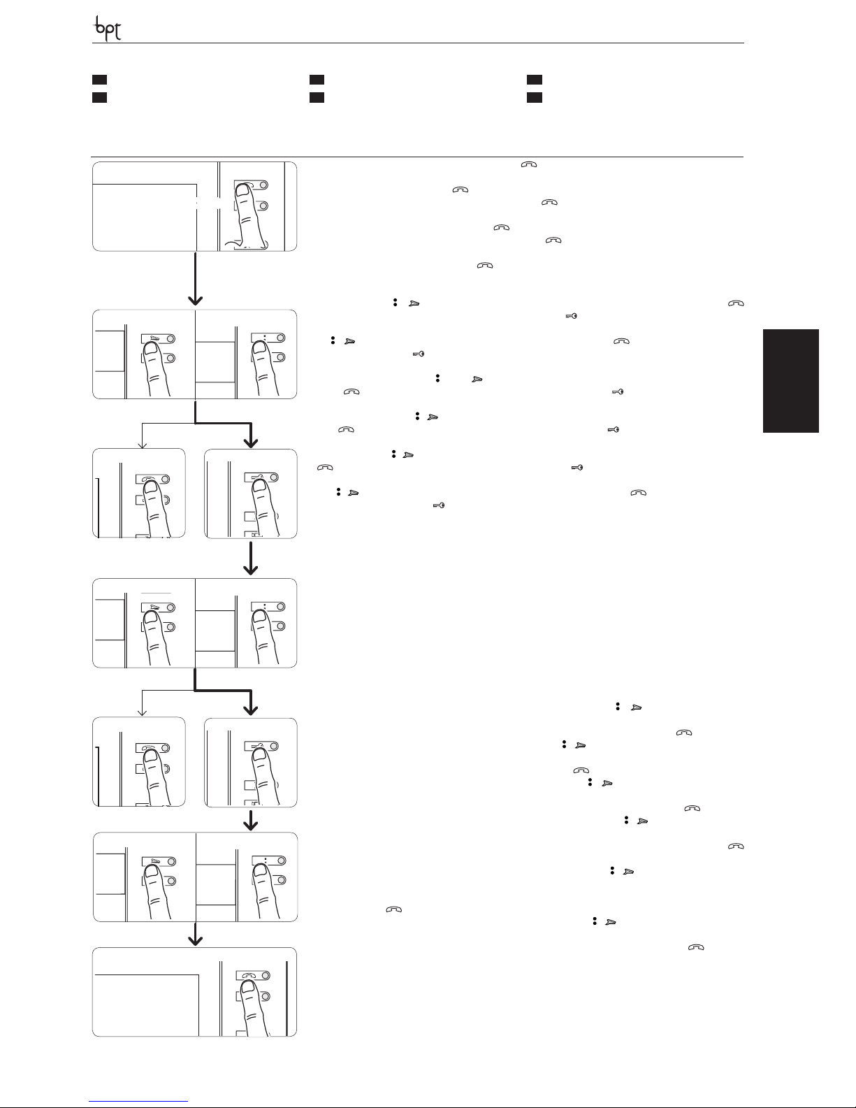
OPHERA
OPHERA LYNEA BASICLYNEANOVAMITHOVAS/100.30
DVC/01
DVC/01 ME
19
Ingresso in Programmazione. Premere per 5 volte il pulsante entro 5 s. Un breve segnale acustico conferma l’ingresso in program-
mazione a.
Accessing programming. Press the button 5 times within 5 s. A brief acoustic signal will conrm that programming has been accessed a.
Einstieg in die Programmierung. Innerhalb 5 Sek. fünf,mal die Taste drücken. Ein kurzer Signalton bestätigt den Einstieg in die Pro-
grammierung a.
Entrée en Programmation. Appuyer 5 fois sur la touche dans les 5 s. Un bref signal sonore conrme l’entrée dans la programmation a.
Entrada en la modalidad de Programación Pulse 5 veces el botón antes de 5 s. Una breve señal acústica conrmará que se ha
entrado en la modalidad de programación a.
Entrada em Programação. Aperte 5 vezes o botão por 5 s. Um breve sinal acústico conrmará a entrada em programação a.
Programmazione della melodia associata alla chiamata dal posto esterno (1 segnale acustico). Per ascoltare in sequenza le
melodie premere il tasto ( ) ( nel modello OPHERA/B) b. Per selezionare la melodia ed uscire dalla programmazione premere il tasto
c. Per selezionare la melodia e proseguire con la programmazione premere il tasto d.
Programming the melody associated to the call from the entry panel (1 acoustic signal). To hear the melodies in sequence, press the
key ( in the OPHERA/B model) b. To select the melody and exit programming, press the key c. To select the melody and continue
with programming, press the key d.
Programmierung der Melodie, die mit dem Anruf von der Außenstation verknüpft ist (1 akustisches Signal). Um die Melodien nacheinander zu hören, die Taste drücken ( im Modell OPHERA/B) b. Zum Wählen der Melodie und Verlassen der Programmierung,
die Taste drücken c. Zum Wählen der Melodie und fortsetzen der Programmierung, die Taste drücken d.
Programmation de la mélodie associée à l’appel provenant du poste extérieur (1 signal sonore). Pour écouter les mélodies en
séquence, appuyer sur la touche ( sur le modèle OPHERA/B) b. Pour sélectionner la mélodie et quitter la programmation, appuyer sur la
touche c. Pour sélectionner la mélodie et continuer la programmation, appuyer sur la touche d.
Programación de la melodía asociada a la llamada desde la placa exterior (1 señal acústica). Para escuchar en secuencia las
melodías, pulse el botón ( en el modelo OPHERA/B) b. Para seleccionar la melodía y salir de la modalidad de programación, pulse el botón
c. Para seleccionar la melodía y proseguir con la programación, pulse el botón d.
Programação da melodia associada à chamada da placa botoneira (1 sinal acústico). Para ouvir as melodias em sequência aperte a
tecla ( no modelo OPHERA/B) b. Para seleccionar a melodia e sair da programação, aperte a tecla c. Para seleccionar a melodia e
continuar a programação, aperte a tecla d.
Programmazione della melodia associata alla chiamata dal pianerottolo (2 segnali acustici). Per questo tipo di programmazione e f g procedere come la “Programmazione della melodia associata alla chiamata dal posto esterno” precedentemente descritta.
Programming the melody associated with the doorbell (2 acoustic signals). For this type of programming e f g proceed as
previously described for “Programming the melody associated to the call from the entry panel”.
Programmierung der Melodie, die mit dem Anruf vom Treppenhaus verknüpft ist (2 akustische Signale). Für diese Programmierungsart e f g wie bei der zuvor beschriebenen “Programmierung der Melodie, die mit dem Anruf von der Außenstation verknüpft
ist” vorgehen.
Programmation de la mélodie associée à l’appel provenant du palier (2 signaux sonores). Pour ce type de programmation e f
g procéder comme pour la “Programmation de la mélodie associée à l’appel provenant du poste extérieur” décrite précédemment.
Programación de la melodía asociada a la llamada desde el rellano (2 señales acústicas). Para este tipo de programación
e f g siga los mismos pasos que para la “Programación de la melodía asociada a la llamada desde la placa exterior” descrita previamente.
Programação da melodia associada à chamada do patamar (2 sinais acústicos). Para este tipo de programação e f g continue
como para a “Programação da melodia associada à chamada da placa botoneira” descrita anteriormente.
Programmazione del numero di squilli di chiamata (3 segnali acustici). Premere il tasto ( ) ( nel modello OPHERA/B) tante volte
quanti sono gli squilli che si è scelto per la chiamata (da 1 a 6 squilli) h. Dopo 3 s dall’ultima pressione del tasto verrà riprodotta la chiamata selezionata
per il numero di squilli prescelto. Per salvare la melodia scelta ed uscire completamente dalla programmazione premere il tasto i.
Programming the number of call rings (3 acoustic signals). Press the key ( in the OPHERA/B model) the number of times equal to
the rings selected for the call (1 to 6 rings) h. 3 s after the key is pressed the last time, the call selected for the selected number of rings will be will be
reproduced. To save the selected memory and exit programming completely, press the key i.
Programmierung der Anzahl der Ruftöne (3 akustische Signale). Die Taste ( im Modell OPHERA/B) so oft drücken, wie
Ruftöne für den Anruf gewünscht werden (1 bis 6 Ruftöne) h. 3 s nach dem letzten Drücken der Taste wird der gewählte Anruf mit der Anzahl
der festgelegten Ruftöne wiederholt. Zum Speichern der Melodie und vollständigen Verlassen der Programmierung, die Taste drücken i.
Programmation du nombre de sonneries d’appel (3 signaux sonores). Appuyer sur la touche ( sur le modèle OPHERA/B) autant
de fois que le nombre de sonneries que l’on a choisi pour l’appel (de 1 à 6 sonneries) h. 3 s après la dernière pression sur la touche, l’appel sélectionné
pour le nombre de sonneries choisi sera eectué. Pour sauvegarder la mélodie et quitter complètement la programmation, appuyer sur la touche
i.
Programación del número de tonos de llamada (3 señales acústicas). Pulse el botón ( en el modelo OPHERA/B) un número
de veces igual a los tonos que se desean para la llamada (de 1 a 6 tonos) h. Pasados 3 s desde la última vez que se pulse el botón, se reproducirá
la llamada seleccionada con el número de tonos elegido. Para guardar la melodía seleccionada y salir completamente de la modalidad de programación, pulse el botón i.
Programação do número de toques de chamada (3 sinais acústicos). Aperte a tecla ( no modelo OPHERA/B) tantas vezes quantas
desejar para o número de toques da chamada (de 1 a 6 toques) h. Após 3 s, a partir da última vez que apertou a tecla, será reproduzida a chamada
seleccionada para o número de toques desejado. Para salvar a melodia escolhida e sair totalmente da programação aperte a tecla i.
X 5
beep
OPHERA/B
OPHERA
a
b
c
d
y Per la programmazione della chiamata, vedere la docu�
mentazione dei posti esterni.
y For call programming, see the entry panel documentation.
y Für die Rufprogrammierung, siehe Unterlagen der Außen�
stationen.
y Pour la programmation de l’appel, voir la documentation
des postes extérieurs.
y Para la programación de la llamada, consulte la documen�Para la programación de la llamada, consulte la documen�
tación de las placas exteriores.
y Para programar a chamada, consulte a documentação das
placas botoneiras.
OPHERA/B
OPHERA
h
i
OPHERA/B
OPHERA
e
f
g
IT
PROGRAMMAZIONE
EN
PROGRAMMING
DE
PROGRAMMIERUNG
FR
PROGRAMMATION
ES
PROGRAMACIÓN
PT
PROGRAMAÇÃO
Page 20
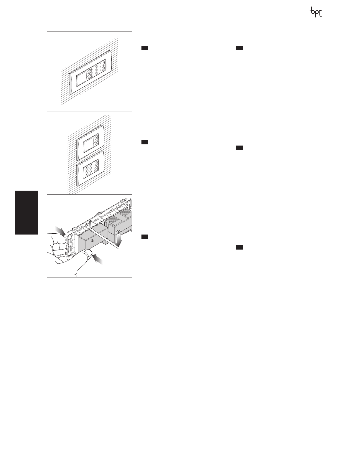
NOVA
OPHERALYNEA BASIC LYNEA NOVA MITHO VAS/100.30
DVC/01
DVC/01 ME
NOVA
IT
INSTALLAZIONE
Videocitofono a colori vivavoce. Il modulo monitor può essere installato, abbinato al modulo
vivavoce NC/321, in unica scatola incasso (fig.
1), oppure da solo abbinato al modulo vivavoce
(fig. 2).
In quest’ultimo caso la distanza fra i due moduli è
subordinata dalla lunghezza (24 cm) del cablaggio in dotazione.
Murare la scatola incasso a filo muro e ad una altezza adeguata all’utente.
Per estrarre i moduli dal telaio agire sulle alette
di bloccaggio e spingere dalla parte posteriore
(figura 3).
Di seguito alcuni esempi di montaggio del videocitofono con alcune placche in commercio.
EN
INSTALLATION
Colour hands-free video entry control The monitor module can be installed in combination with
the NC/321 hands-free module in a single recessed box (fig. 1), or on its own in combination
with the hands-free module (fig. 2).
In the latter case, the distance between the
modules will depend on the length (24 cm) of
the supplied cable.
Install the recessed box flush with the wall at a
suitable height for the user.
To extract the frame modules, use the locking
tabs and push from the rear (figure 3).
Some installation examples of the video entry
control with some plates available on the market
are shown below
DE
INSTALLATION
Farbiges Videosprechgerät mit Freisprechanlage
Das Monitormodul kann zusammen mit dem
Freisprechmodul NC/321 in einem einzigen UPKasten (Abb. 1) oder alleine, in Kombination mit
dem Freisprechmodul, (Abb. 2) eingebaut werden.
In diesem letzteren Fall ist der Abstand zwischen
den Modulen von der Länge des mitgelieferten
Kabels (24 cm) abhängig.
Das UP-Gehäuse bündig in einer für den Benutzer geeigneten Höhe bündig einbauen.
Zum Herausnehmen der Module aus dem Rahmen auf die Befestigungsrippen einwirken und
von der Rückseite Druck ausüben (Abbildung 3).
Nachfolgende einige Montagebeispiele der Videosprechanlage mit einigen im Handel befindlichen Tableaus.
1
3
FR
INSTALLATION
Portier vidéo à couleurs vive-voix. Le module
moniteur peut être installé, associé au module
vive-voix NC/321, dans un seul boîtier encastré
(fig. 1) ou seul, associé au module vive-voix (fig.
2).
Dans ce dernier cas, la distance entre les deux
modules dépend de la longueur (24 cm) du câblage fourni.
Murer le boîtier à encastrer au ras du mur et à
une hauteur adéquate pour l’utilisateur.
Pour extraire les modules du châssis, agir sur les
ailettes de blocage et pousser de l’arrière (figure
3).
Ci-dessous, quelques exemples de montage de
portier vidéo avec quelques plaques sur le marché.
ES
INSTALACIÓN
Videoportero en color manos libres. El módulo
monitor puede instalarse, junto con el módulo
manos libres NC/321, en una única caja empotrable (fig. 1), o solo, junto con el módulo manos
libres (fig.2).
En este último caso, la distancia entre los dos
módulos está supeditada a la longitud (24 cm)
del cableado incluido en el suministro.
Encastre la caja empotrable a ras de la pared y a
una altura adecuada para el usuario.
Para extraer los módulos del armazón, intervenga sobre las aletas de fijación y empuje desde la
parte posterior (figura 3).
A continuación se dan algunos ejemplos de
montaje del videoportero con algunas placas
presentes en el mercado.
PT
INSTALAÇÃO
Vídeo porteiro a cores alta voz. O módulo monitor pode ser instalado, combinado ao módulo
alta voz NC/321, em única caixa de encastre (fig.
1), ou sozinho combinado ao módulo alta voz
(fig. 2).
Neste último caso a distância entre os dois módulos é subordinada pelo comprimento (24 cm)
da cablagem em dotação.
Murar a caixa de encastre de modo que fique
alinhada ao muro e a uma altura adequada para
o utente.
Para extrair os módulos da estrutura agir nas
abas de bloqueio e empurrar pela parte traseira
(figura 3).
A seguir, alguns exemplos de montagem do
vídeo porteiro com algumas placas em comércio.
2
20
Page 21
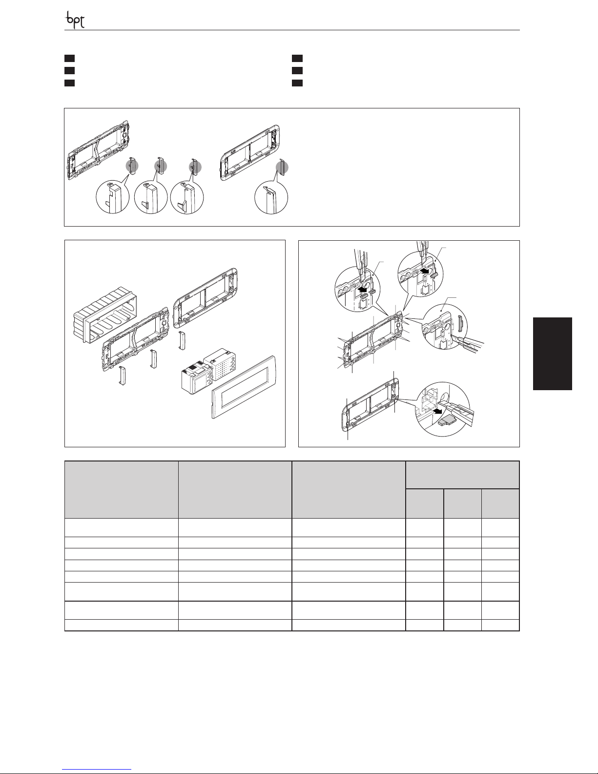
NOVA
OPHERA LYNEA BASICLYNEANOVAMITHOVAS/100.30
DVC/01
DVC/01 ME
TT
P1
TN
P2
P3
Serie civili�Civil series
Serien für den Privatbereich
Séries résidentielles
Series residenciales�Séries civis
Tipo Telaio�Frame type
Rahmentyp�Type de châssis
Tipo de armazón�Tipo de estrutura
Agganci da eliminare (g. 18)
Hooks to eliminate (g. 18)
Zu entfernende Aufhängungen (Abb. 18)
Crochets à éliminer (g. 18)
Enganches a eliminar (g. 18)
Engates a eliminar (g. 18)
Tipo adattatore�Adaptor type
Adaptermodell�Type d’adaptateur
Tipo de adaptador�Tipo de adaptador
P1 P2 P3
BTICINO Living International art.
L4807 o Light art. N4807
TT 1-3 C B C
BTICINO Matix
TT 1-2-3
– B –
VIMAR Plana, Eikon
TT 1
B B B
GEWISS Playbus
TT 1-2-3-4
D B D
GEWISS Playbus Young
TT 2-4
D C D
VIMAR Idea, Idea Rondó,
AVE Sistema 45, Banquise
TT – D B D
BTICINO Axolute, LEGRAND, Cross,
Vela, GEWISS System
TN 1 – F –
ABB serie Elos
TN 1
C F C
TT
A B C
TN
D
TT) Telaio trasparente/Transparent frame/Tran-
sparenter Rahmen/Châssis transparent/Armazón
transparente/Estrutura transparente.
A) Adattatore da 8,5 mm/8.5 mm adaptor/Adap-
ter 8,5 mm/Adaptateur de 8,5 mm/Adaptador de
8,5 mm/Adaptador de 8,5 mm.
B) Adattatore da 6,5 mm/6.5 mm adaptor/Adap-
ter 6,5 mm/Adaptateur de 6,5 mm/Adaptador de
6,5 mm/Adaptador de 6,5 mm.
C) Adattatore da 4,5 mm/4.5 mm adaptor/Adap-
ter 4,5 mm/Adaptateur de 4,5 mm/Adaptador de
4,5 mm/Adaptador de 4,5 mm.
TN) Telaio nero/Black frame/Schwarzer Rahmen/
Châssis noir/Armazón negro/Estrutura preta.
D) Adattatore da 3,2 mm/3.2 mm adaptor/Adap-
ter 3,2 mm/Adaptateur de 3,2 mm/Adaptador de
3,2 mm/Adaptador de 3,2 mm.
4
2
2
4
1
3
1
1
2-3
4
4
1
1
3
4
2
2
1
1
1
1
TN
TT
21
IT
INSTALLAZIONE IN SCATOLA DA 6 MODULI
EN
INSTALLATION IN A BOX WITH 6 MODULES
DE
INSTALLATION IN GEHÄUSE FÜR 6 MODUL
FR
INSTALLATION EN BOÎTIER DE 6 MODULES
ES
INSTALACIÓN EN CAJA DE 6 MÓDULOS
PT
INSTALAÇÃO EM CAIXA DE 6 MÓDULOS
Page 22
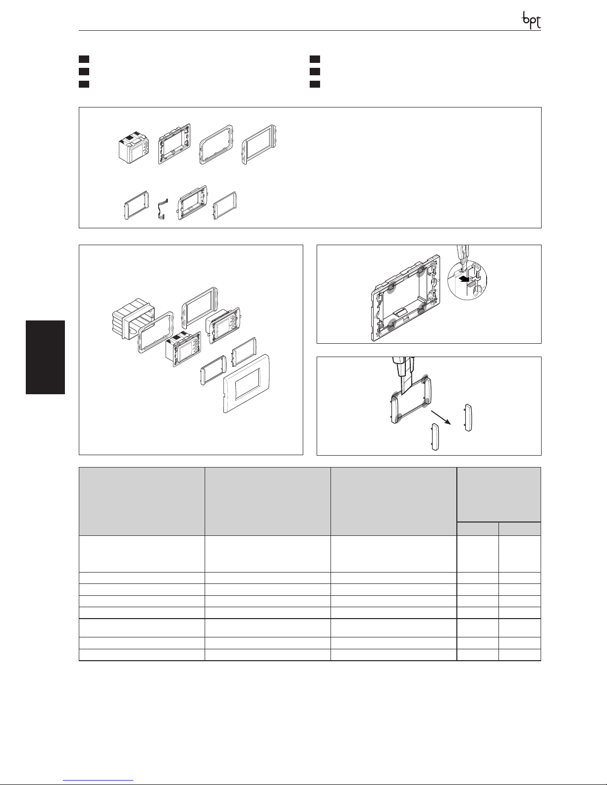
NOVA
OPHERALYNEA BASIC LYNEA NOVA MITHO VAS/100.30
DVC/01
DVC/01 ME
A) Modulo monitor/Monitor module/ Monitormo-
dul/Module moniteur/ Módulo monitor/ Módulo
monitor
TT) Telaio trasparente/Transparent frame/Tran-
sparenter Rahmen/Châssis transparent/Armazón
transparente/Estrutura transparente.
B�C�D�F) Adattatori per serie civili/Adaptors
for civilian series/Adapter für Serien zum zivilen
Gebrauch/Adaptateurs pour séries résidentielles/
Adaptadores para series civiles/Adaptadores para
séries civis.
E) Cablaggio/Cable/Kabel/Câblage/Cableado/
Cablagem
TN) Telaio nero/Black frame/Schwarzer Rahmen/
Châssis noir/Armazón negro/Telaio nero.
TT
A
B C
TN
D
E F
TT
P1
TN
P2
1
TT
Serie civili�Civil series
Serien für den Privatbereich
Séries résidentielles
Series residenciales�Séries civis
Tipo Telaio�Frame type
Rahmentyp�Type de châssis
Tipo de armazón�Tipo de estrutura
Agganci da eliminare (g. 1)
Hooks to eliminate (g. 1)
Zu entfernende Aufhängungen (Abb. 1)
Crochets à éliminer (g. 1)
Enganches a eliminar (g. 1)
Engates a eliminar (g. 1)
Tipo adattatore
Adaptor type
Adaptermodell
Type d’adaptateur
Tipo de adaptador
Tipo de adaptador
P1 P2
BTICINO Living International art. L4803,
Light art. N4803,
VIMAR Plana, Eikon
LEGRAND Vela, Cross
TT – – –
VIMAR Idea o Rondò
TT –
B D
AVE Sistema 45, Banquise
TT –
C D
GEWISS Playbus
TT X
– D (*)
GEWISS Playbus Young
TT X
– D
BTICINO Axolute
GEWISS System
TN – – F
BTICINO Luna
TN X – –
ABB Elos
TN X
D (*)
D
D (*)
IT
INSTALLAZIONE IN SCATOLA DA 3 MODULI
EN
INSTALLATION IN A BOX WITH 3 MODULES
DE
INSTALLATION IN GEHÄUSE FÜR 3 MODUL
FR
INSTALLATION EN BOÎTIER DE 3 MODULES
ES
INSTALACIÓN EN CAJA DE 3 MÓDULOS
PT
INSTALAÇÃO EM CAIXA DE 3 MÓDULOS
22
Page 23
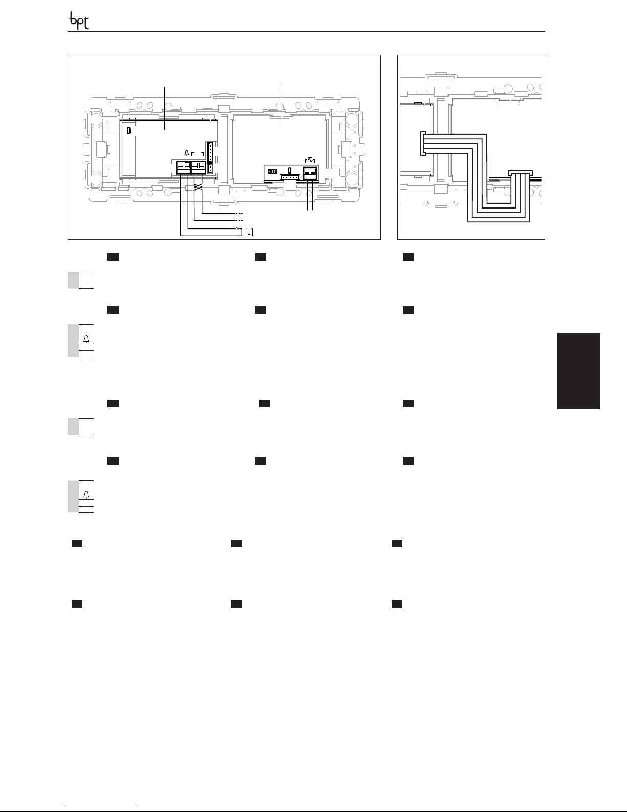
NOVA
OPHERA LYNEA BASICLYNEANOVAMITHOVAS/100.30
DVC/01
DVC/01 ME
23
SUB
LACOL
B
M1
CN1
CN1
CN3
SW1
SW1
SW2
M1
12-16VAC
14-18VDC
CN1
CN1
IT
MORSETTIERE MODULO AUDIO
EN
AUDIO MODULE TERMINAL
BOARD
DE
KLEMMLEISTEN AUDIO
MODUL
M1
~
da 12÷16 Vca o 14÷18 Vcc
alimentazione locale
Power supply local
From 12÷16 V AC or 14÷18 V DC
Stromversorgung örtlich
zu 12÷16 VAC oder 14÷18 VDC
~
IT
MORSETTIERE MODULO VIDEO
EN
VIDEO MODULE TERMINAL
BOARD
DE
KLEMMLEISTEN VIDEO
MODUL
M1
–
Chiamata pianerottolo Personal door-bell Anruf vom Treppenhaus
B
Ingresso linea BUS BUS line input Eingang BUS-Leitung
FR
BORNIERS MODULE AUDIO
ES
BORNERAS MÓDULO AUDIO
PT
PAINÉIS DE TERMINAIS
MÓDULO ÁUDIO
M1
~
Alimentation local
de 12÷16 Vca ou 14÷18 Vcc
Alimentación local
de 12÷16 Vca ó 14÷18 Vcc
Alimentação local
desde 12÷16 Vca ou 14÷18 Vcc
~
FR
BORNIERS MODULE VIDÉO
ES
BORNERAS MÓDULO VÍDEO
PT
PAINÉIS DE TERMINAIS
MÓDULO VÍDEO
M1
–
Appel du palier
Llamada desde el rellano Chamada do patamar
B
Entrée ligne BUS Entrada línea BUS Entrada linha BUS
MODULO AUDIO�AUDIO MODULE
AUDIOMODUL�MODULE AUDIO
MÓDULO AUDIO�MÓDULO ÁUDIO
MODULO VIDEO�VIDEO MODULE
VIDEOMODUL�MODULE VIDÉO
MÓDULO VÍDEO�MÓDULO VÍDEO
IT
FUNZIONE DEI CONNETTORI
EN
FUNCTION OF CONNECTORS
DE
FUNKTION DER STECKVERBINDER
CN1: connettori da utilizzare per collegare, tramite l’apposito cablaggio, il modulo audio al modulo video.
CN1: connectors to use for connecting the audio
module to the video module with the appropriate
cable.
CN1: Steckverbinder, die für den Anschluss des
Audiomoduls an das Videomodul mit dem entsprechenden Kabel benutzt werden.
CN3: non utilizzato. CN3: not used. CN3: nicht benutzt.
FR
FONCTION DES CONNECTEURS
ES
FUNCIÓN DE LOS CONECTORES
PT
FUNÇÃO DOS CONECTORES
CN1: connecteurs à utiliser pour brancher, à l’aide
du câblage prévu à cet effet, le module audio au
module vidéo.
CN1: conectores para conectar, mediante el cableado previsto, el módulo audio al módulo vídeo.
CN1: conectores a utilizar para ligar, através da
relativa cablagem, o módulo áudio ao módulo
vídeo.
CN3: non utilisé. CN3: no se utiliza. CN3: não utilizado.
Page 24
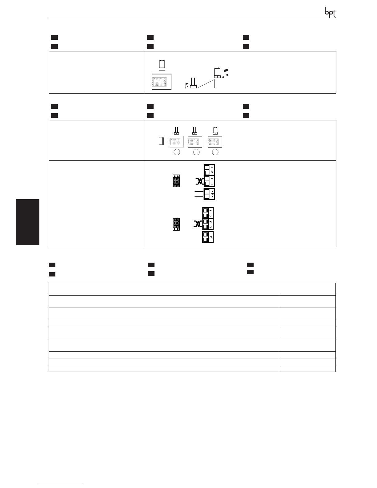
NOVA
OPHERALYNEA BASIC LYNEA NOVA MITHO VAS/100.30
DVC/01
DVC/01 ME
24
IT
SELEZIONI MODULO AUDIO
EN
AUDIO MODULE SELECTIONS
DE
WAHLEN AUDIOMODUL
FR
SÉLECTIONS MODULE AUDIO
ES
SELECCIONES MÓDULO AUDIO
PT
SELECÇÕES MÓDULO ÁUDIO
SW1 (Attenuazione della chiamata)
SW1 (Call attenuated)
SW1 (Abschwächung des Anrufs)
SW1(Atténuation de l’appel)
SW1 (Atenuación de la llamada)
SW1(Atenuação da chamada)
SW1
SW1
SW1
IT
SELEZIONI MODULO VIDEO
EN
VIDEO MODULE SELECTIONS
DE
WAHLEN VIDEOMODUL
FR
SÉLECTION MODULE VIDÉO
ES
SELECCIONES MÓDULO VÍDEO
PT
SELECÇÕES MÓDULO VÍDEO
SW1 (Resistenza di chiusura)
SW1 (Resistive load termination)
SW1 (Schließwiderstand)
SW1 (Résistance de fermeture)
SW1 (Resistencia de cierre)
SW1 (Resistência de fecho)
SW1 SW1
SW1
1 2
3
XDV/304
SW2 (Selezione sorgente di alimentazione)
SW2 (Selects power source)
SW2 (Auswahl der Stromquelle)
SW2 (Sélection source d’alimentation)
SW2(Selección de fuente de alimentación)
SW2(Selección de fuente de alimentación)
SW2
BUS
LOCAL
M1
B
Alimentazione separata
Separate power supply
Getrennte Versorgung
Alimentation séparée
Alimentación separada
Alimentação separada
M1
SW2
LOCAL
BUS
B
Alimentazione da BUS (max 1 solo derivato)
Power supply from BUS (max. only 1 extension)
Stromversorgung über BUS (max. nur 1 Innensprechstelle)
Alimentation depuis BUS (1 seul poste intérieur max)
Alimentación desde BUS (máx. 1 solo derivado)
Alimentação de BUS (max somente 1 derivado)
Alimentazione da BUS-Power supply from BUS-Stromversorgung über BUS-Alimentation depuis BUS-Alimentación desde BUS-Alimentação de BUS
15÷20 VDC
Alimentazione locale-Supply voltage local-Stromversorgung örtlichAlimentation local-Alimentación local-Alimentação local
12-16 VAC; 14-18 VDC
Assorbimento-Absorption-StromaufnahmeAbsorption-Consumo-Consumo
220 mA max (<1 mA standby)
Dimensioni-Dimensions-Maße-Dimensions-Dimensiones-Dimensões 206x215x59 mm
Temperatura di stoccaggio-Storage temperature-Lagerungstemperatur
Température de stockage-Temperatura de almacenamiento-Temperatura de armazenagem
-25 °C +70 °C
Temperatura di funzionamento-Operating temperature-Betriebstemperatur
Température de fonctionnement -Temperatura de funcionamiento-Temperatura de funcionamento
0 °C +35 °C
Grado IP-IP Degree-IP-Grad-Degré IP-Grado IP-Grau IP IP 20
Standard video-Standard video-Videostandard-Standard vidéo-Estándar de vídeo-Standard vídeo PAL/NTSC
Display-Display-Display-Display-Display-Display LCD TFT 2’’
IT
CARATTERISTICHE TECNICHE
FR
CARACTÉRISTIQUES TECHNIQUES
EN
TECHNICAL FEATURES
ES
CARACTERÍSTICAS TÉCNICAS
DE
TECHNISCHE MERKMALE
PT
CARACTERÍSTICAS TÉCNICAS
Page 25

NOVA
OPHERA LYNEA BASICLYNEANOVAMITHOVAS/100.30
DVC/01
DVC/01 ME
25
Page 26
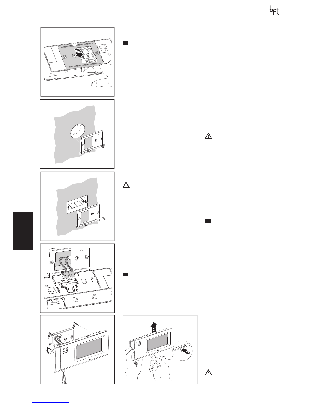
OPHERALYNEA BASIC LYNEA NOVA MITHO VAS/100.30
DVC/01
DVC/01 ME
MITHO
MITHO
IT
INSTALLAZIONE
ATTENZIONE. Per la pulizia utilizzare solo
panni morbidi ed asciutti oppure leggermente inumiditi con acqua; non utilizzare alcun
tipo di prodotto chimico.
Utilizzare il terminale solo con la penna in dotazione o con strumenti simili; non utilizzare
utensili, penne o altri strumenti appuntiti che
potrebbero danneggiare il display e comprometterne il funzionamento.
Non esporre lo schermo LCD alla luce diretta
del sole.
Sganciare l’apparecchio dal supporto metallico,
facendolo scorrere su di esso dopo aver premuto
il pulsante plastico (fi gura 1).
Fissare il supporto metallico alla scatola d’incasso tonda Ø 60 mm (fi gura 2) oppure alla scatola
rettangolare 503 utilizzando le viti in dotazione e
rispettando l’indicazione ALTO (fi gura 3).
La scatola deve essere installata ad un’altezza
adeguata all’utente.
Evitare il serraggio eccessivo delle viti.
Eff ettuati i collegamenti, agganciare il videoterminale al supporto metallico (fi gura 5).
Per sganciare l’apparecchio dal supporto metallico premere il gancio plastico e sollevare il terminale (fi gura 6).
Inserimento/rimozione della scheda MICRO
SD
ATTENZIONE
Prima di inserire o togliere la MICRO SD, togliere l’alimentazione al videoterminale rimuovendo le morsettiere M1 e M2 ( gura 7).
Funzione del pulsante RESET
Ogni volta che anomalie di funzionamento, interventi e altre ragioni tecniche richiedono il
reset dell’apparecchio, premere leggermente
il pulsante collocato all’interno dell’apertura indicata in fi gura 8; rilasciare il pulsante appena
lo schermo si oscura e attendere che riappaia il
menù principale prima di riprendere l’uso normale dell’apparecchio.
NOTA. Questa operazione NON comporta la
cancellazione di eventuali programmi che saranno ripristinati, assieme agli altri dati, al riavvio
dell’apparecchio.
EN
INSTALLATION
WARNING. Only use soft, dry or slightly damp
cloths to clean the terminal; do not use any
chemical products.
Use the terminal only with the pen provided
or with similar instruments. Do not use tools,
pens or other sharp instruments which may
damage the display and compromise operation.
Do not expose the LCD screen to direct sunlight.
Remove the unit from the metallic support by sliding it after pressing the plastic button (fi gure 1).
Fasten the metallic support to the round built-in
box of Ø 60 mm (fi gure 2) or to the rectangular
box 503 using the provided screws and observing the UP indication.
The recessed box must be fi tted at a suitable
height in relation to the user.
Avoid excessive tightening of the screws.
Once the connections have been made, hook
the video terminal to the metal support (fi gure
5).
To release the unit from the metal support, press
the plastic hook and lift the terminal (fi gure 6).
Insertion/removal of the MICRO SD card
ATTENTION
Before inserting or removing the MICRO SD,
cut o the power supply to the video terminal by removing the terminal boards M1 and
M2 ( gure 7).
Function of the RESET button
Each time operating malfunctions, work or other
technical reasons make it necessary to reset the
unit, lightly press the button located inside the
opening shown in fi gure 8; release the button as
soon as the screen darkens and wait for the main
menu to reappear before resuming normal use
of the unit.
NOTE. This operation does NOT delete any programmes, which will be restored, along with
other data, when the unit is restarted.
DE
INSTALLATION
ACHTUNG. Für die P ege nur weiche und trockene oder mit wenig Wasser angefeuchtete
Tücher verwenden, keine chemischen Produkte benutzen.
Das Terminal nur mit dem beiliegenden Stift
oder einem ähnlichen Instrument benutzen.
Keine Werkzeuge, Schreibgeräte oder andere spitze Gegenstände benutzen, die das
Display beschädigen und die Funktionalität
beeinträchtigen könnten.
Den LCD-Bildschirm nicht direktem Sonnenlicht aussetzen.
Das Gerät an der Metallhalterung aushängen,
dabei nach dem Drücken der Kunststoff taste
(Abbildung 1) das Gerät auf der Halterung verschieben.
Die Metallhalterung am runden Unterputzkasten
Ø 60 mm (Abbildung 2A) oder am rechteckigen
Gehäuse 503 befestigen, hierfür die beiliegenden Schrauben benutzen und die Angabe OBEN
(Abbildung 3) beachten.
Der Kasten muss auf für den Benutzer geeigneter
Höhe installiert werden.
Die Schrauben nicht zu stark anziehen.
Nach den Anschlüssen das Videoterminal an der
Metallhalterung einhängen (Abbildung 5).
Um das Gerät von der Metallhalterung auszuklinken den Plastikhaken drücken, und das Terminal
anheben (Abbildung 6).
Einsetzen/Entfernen der Platine MICRO SD
ACHTUNG
Vor dem Einstecken oder Herausnehmen der
MICRO SD, die Versorgung des Videotermi-
2
1
4
5
6
3
1
2
26
Page 27
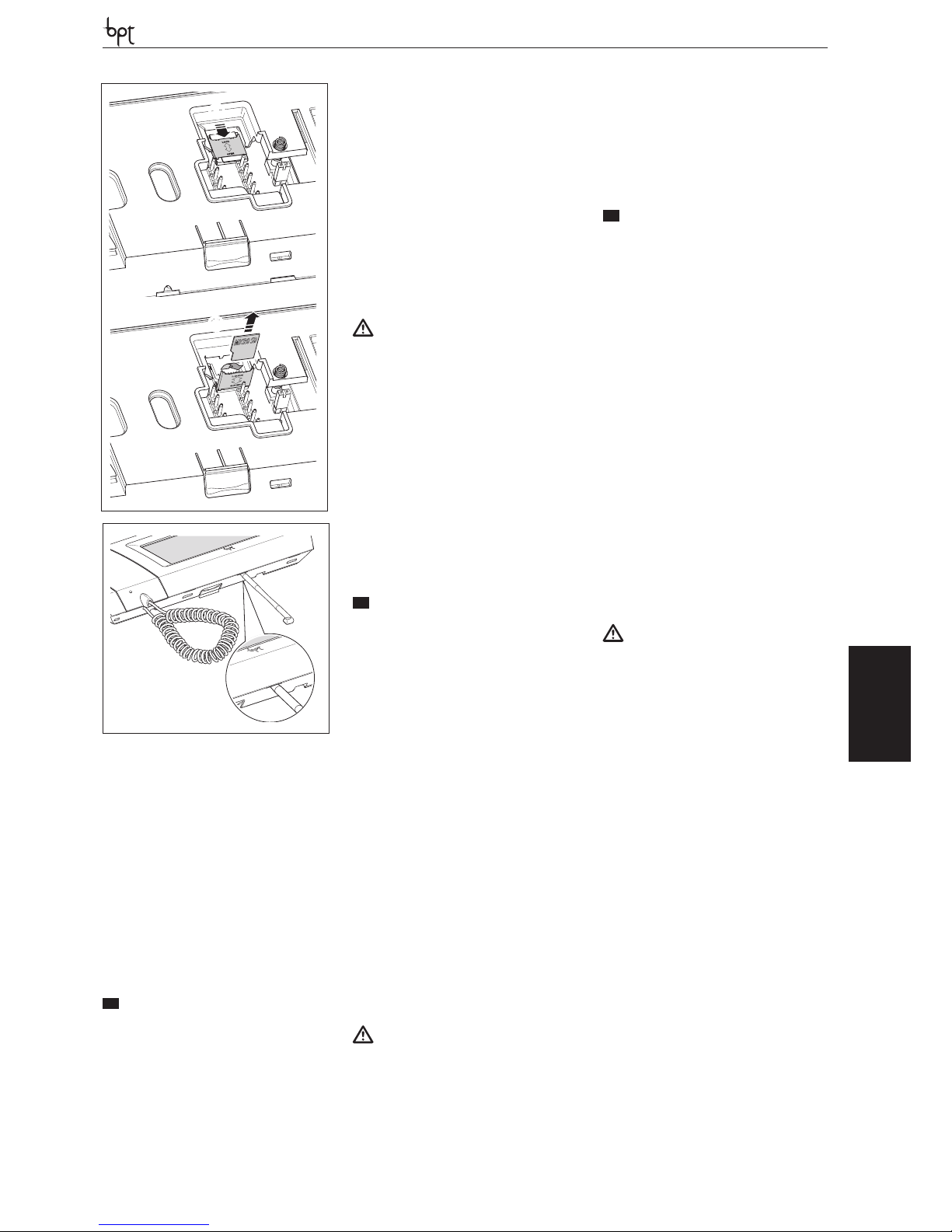
OPHERA LYNEA BASICLYNEANOVAMITHOVAS/100.30
DVC/01
DVC/01 ME
MITHO
MICRO SD
7
1
2
nals durch Abnehmen der Klemmleisten M1
und M2 (Abbildung 7) abtrennen.
Funktion der Taste RESET
Immer wenn Betriebsstörungen, Eingriffe oder
andere technische Ursachen die Rücksetzung
des Gerätes verlangen, die Taste innen in der
Öffnung, die in Abbildung 8 gezeigt wird, leicht
drücken. Sobald der Bildschirm dunkel wird, die
Taste wieder loslassen und bevor man das Gerät
wieder normal benutzt, warten, dass das Hauptmenü erscheint.
HINWEIS Dieser Vorgang führt NICHT zur Löschung eventueller Programme. Diese werden
zusammen mit den anderen Daten beim Neustart des Geräts wieder geladen.
FR
INSTALLATION
ATTENTION. Pour le nettoyage, n’utiliser que
des chions doux et secs ou légèrement imbibés d’eau; n’utiliser aucun type de produit
chimique.
N’utiliser le terminal qu’avec le stylet fourni ou
d’autres instruments semblables; ne pas utiliser d’outils, de crayons ou d’autres instruments
pointus qui pourraient endommager l’écran et
en compromettre le fonctionnement.
Ne pas exposer l’écran LCD aux rayons directs
du soleil.
Retirer l’appareil du support métallique, en le faisant glisser sur celui-ci après avoir appuyé sur la
touche plastique (figure 1).
Fixer le support métallique au boîtier d’encastrement rond Ø 60 mm (figure 2) ou au boîtier
rectangulaire 503, en utilisant les vis fournies et
en respectant l’indication HAUT (figure 3).
Le boîtier doit être installé à une hauteur adéquate pour l’utilisateur.
Éviter de serrer excessivement les vis.
Une fois les raccordements effectués, fixer le portier vidéo au support métallique (figure 5).
Pour retirer l’appareil du support métallique, appuyer sur le clip en plastique et soulever le terminal (figure 6).
Insertion/retrait de la carte MICRO SD
ATTENTION
Avant d’insérer ou de retirer la MICRO SD,
couper l’alimentation du portier vidéo en retirant les borniers M1 et M2 (gure 7).
Fonction de la touche RESET
Chaque fois que des anomalies de fonctionnement, des interventions et d’autres motifs techniques requièrent la remise à zéro de l’appareil,
appuyer légèrement sur la touche située dans
l’ouverture indiquée sur la figure 8; relâcher la
touche dès que l’écran s’obscurcit et attendre
que le menu principal réapparaisse avant de reprendre à utiliser normalement l’appareil.
REMARQUE. Cette opération N’ENTRAÎNE PAS la
suppression des éventuels programmes qui seront rétablis tout comme les autres données, au
moment du redémarrage de l’appareil.
ES
INSTALACIÓN
ATENCIÓN. Para la limpieza utilice solo paños
suaves y secos, o ligeramente humedecidos
en agua; no utilice ningún tipo de producto
químico.
Utilice el terminal solo con el lápiz táctil suministrado o con instrumentos similares; no
utilice herramientas, bolígrafos u otros instrumentos puntiagudos, que podrían causar
daños a la pantalla y comprometer su funcionamiento.
No exponga la pantalla LCD a la luz directa
del sol.
Pulse el botón de plástico y desenganche el
aparato del soporte metálico, haciendo que se
deslice sobre él (figura 1).
Fije el soporte metálico a la caja empotrable redonda Ø 60 mm (figura 2) o a la caja rectangular
503 utilizando los tornillos suministrados y respetando la indicación ALTO (figura 3).
La caja debe instalarse a una altura adecuada
para el usuario.
No apriete demasiado los tornillos.
Una vez realizadas las conexiones, enganche el
terminal de vídeo al soporte metálico (figura 5).
Para desenganchar el aparato del soporte metálico, pulse el gancho de plástico y levante el
terminal (figura 6).
Inserción/extracción de la tarjeta MICRO SD
ATENCIÓN
Antes de insertar o extraer la MICRO SD, desconecte la alimentación del terminal de vídeo quitando las borneras M1 y M2 (gura 7).
Función del botón RESET
Cada vez que, debido a anomalías de funcionamiento, intervenciones y otras razones técnicas,
sea necesario reiniciar el aparato, pulse levemente el botón interno de la apertura indicada en la
figura 8. Suelte el botón en cuanto la pantalla se
oscurezca y espere a que vuelva a aparecer el
menú principal antes de reanudar el uso normal
del aparato.
NOTA. Esta operación NO conlleva la eliminación de los posibles programas: éstos se restablecerán, junto a los demás datos, cuando se vuelva
a poner en marcha el equipo.
PT
INSTALAÇÃO
ATENÇÃO. Para a limpeza utilize apenas panos macios e secos ou ligeiramente humedecidos com água; não utilize qualquer tipo de
produto químico.
Utilize o terminal somente com a caneta fornecida ou com instrumento similares; não
utilize ferramentas, canetas ou outros instrumentos pontiagudos que poderiam danicar
o display e comprometer o seu funcionamento.
Não exponha o ecrã LCD à luz directa do sol.
Desprenda o aparelho do suporte metálico fazendo com que deslize sobre o mesmo depois
de ter carregado no botão de plástico (figura 1).
Fixar o suporte metálico à caixa de encastre redonda Ø 60 mm (figura 2) ou à caixa retangular
503 utilizando os parafusos fornecidos e respeitando a indicação ALTO (figura 3).
A caixa deve ser instalada a uma altura adequada
para o utente.
Evite o aperto excessivo dos parafusos.
Após efectuar as ligações, enganche o terminal
de vídeo no suporte metálico (figura 5).
Para desprender o aparelho do suporte metálico
carregue o gancho plástico e levante o terminal
(figura 6).
Introdução/remoção da placa MICRO SD
ATENÇÃO
Antes de inserir ou retirar a MICRO SD, desligar a alimentação do terminal de vídeo
removendo os painéis de terminais M1 e M2
(gura 7).
Função do botão RESET
Quando, devido a problemas de funcionamento,
intervenções e outras razões técnicas, for necessário efectuar o reset do aparelho, carregue
um pouco o botão colocado na parte interna da
abertura indicada na figura 8; solte o botão assim que o ecrã se tornar escuro e espere a visualização do menu principal antes de voltar a utilizar
o aparelho normalmente.
NOTA. Esta operação NÃO implica a necessidade de apagar eventuais programas que serão
restaurados, junto com os outros dados, ao accionamento do aparelho.
8
Reset
27
Page 28
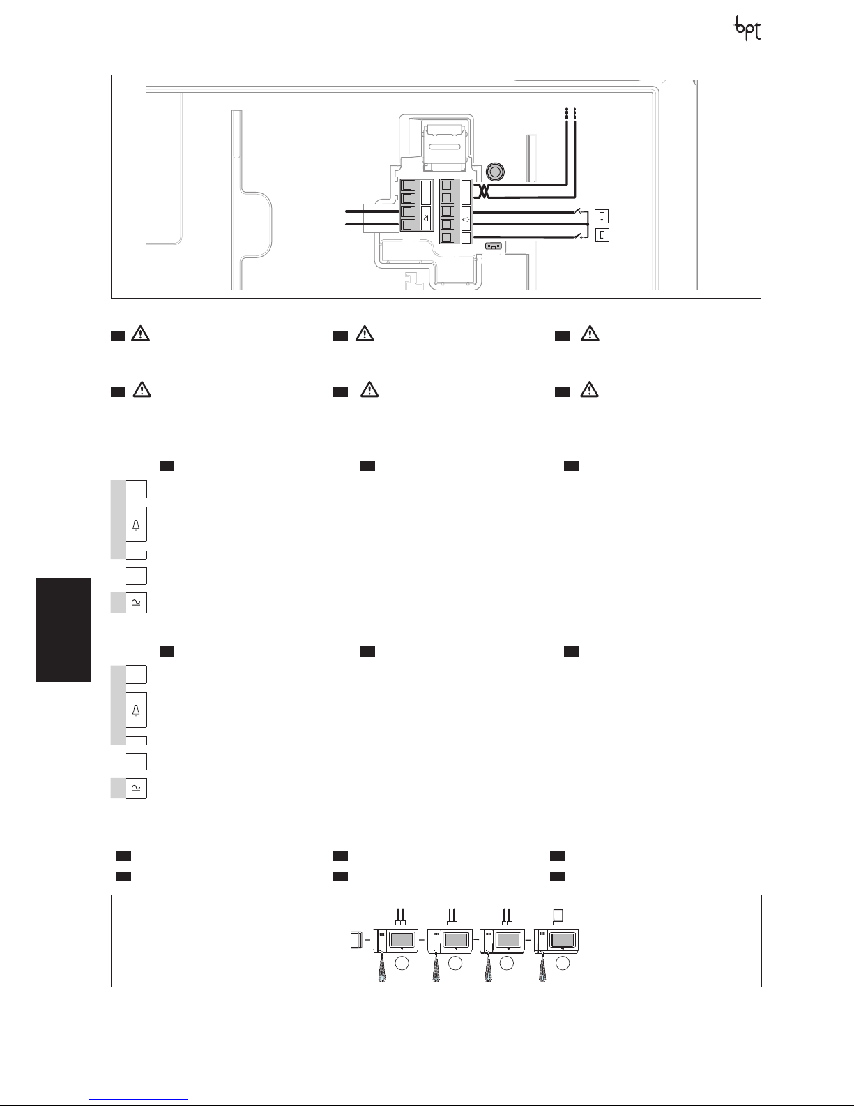
OPHERALYNEA BASIC LYNEA NOVA MITHO VAS/100.30
DVC/01
DVC/01 ME
MITHO
12-16VAC
14-24 VDC
MM
– +
AL
B
IT
MORSETTIERE
EN
TERMINAL BOARDS
DE
KLEMMENBRETTER
M1
B
Ingresso linea BUS BUS line input Eingang BUS-Leitung
–
+
Chiamata pianerottolo
Doorbell Ruf vom Treppenhaus
AL
Ingresso allarme Alarm input Alarmeingang
MM
Non utilizzato Not used Nicht benutzt
M2
alimentazione locale
14÷24 V DC 12÷16 V AC
Power supply local
From 12÷16 V AC or 14÷18 V DC
Stromversorgung örtlich
zu 12÷16 VAC oder 14÷18 VDC
FR
BORNIERS
ES
BORNERAS
PT
RÉGUAS DE BORNES
M1
B
Entrée ligne BUS Entrada línea BUS Entrada linha BUS
–
+
Appel depuis le palier Llamada desde el rellano Chamada do patamar
AL
Entrée alarme
Entrada alarma Entrada alarme
MM
Non utilisé No se utiliza Não utilizado
M2
alimentazione locale
14÷24 V DC 12÷16 V AC
Power supply local
From 12÷16 V AC or 14÷18 V DC
Stromversorgung örtlich
zu 12÷16 VAC oder 14÷18 VDC
M2
SW4
M1
28
IT
SELEZIONI
EN
SELECTIONS
DE
WAHLEN
FR
SÉLECTIONS
ES
SELECCIONES
PT
SELECÇÕES
SW4(Resistenza di chiusura)
SW4 (Resistive load termination)
SW4 (Schließwiderstand)
SW4 (Résistance de fermeture)
SW4 (Resistencia de cierre)
SW4 (Resistência de fecho)
SW4
SW4
SW4
SW4
1 2
3
4
XDV/304
IT
- Una volta eseguiti i cablaggi reinserire atten�
tamente le morsettiere come indicato in gura. Il video �
terminale può essere alimentato sia in corrente continua
che alternata.
EN
- Once wiring is complete, carefully re�insert
the terminal boards as shown in the gure. The video
terminal can be powered by both direct and alternating
current.
DE
- Nach der Verkabelung die Klemmleisten, wie
in der Abbildung gezeigt, wieder vorsichtig einsetzen.
Der Videoterminal kann sowohl mit Gleichstrom als auch
mit Wechselstrom versorgt werden.
FR
- Une fois les câblages eectués, réinsérer
soigneusement les borniers comme indiqué sur la gure.
Le portier vidéo peut être alimenté aussi bien en courant
continu qu’en courant alternatif.
ES
- Una vez realizados los cableados, vuelva a
montar cuidadosamente las borneras como se muestra
en la gura. El terminal de vídeo puede alimentarse tan�
to con corriente continua como con alterna.
PT
- Após ter realizado as cablagens inserir c ui�
dadosamente os painéis de terminais como indicado na
gura. O terminal de vídeo pode ser alimentado seja em
corrente contínua seja alternada.
Page 29
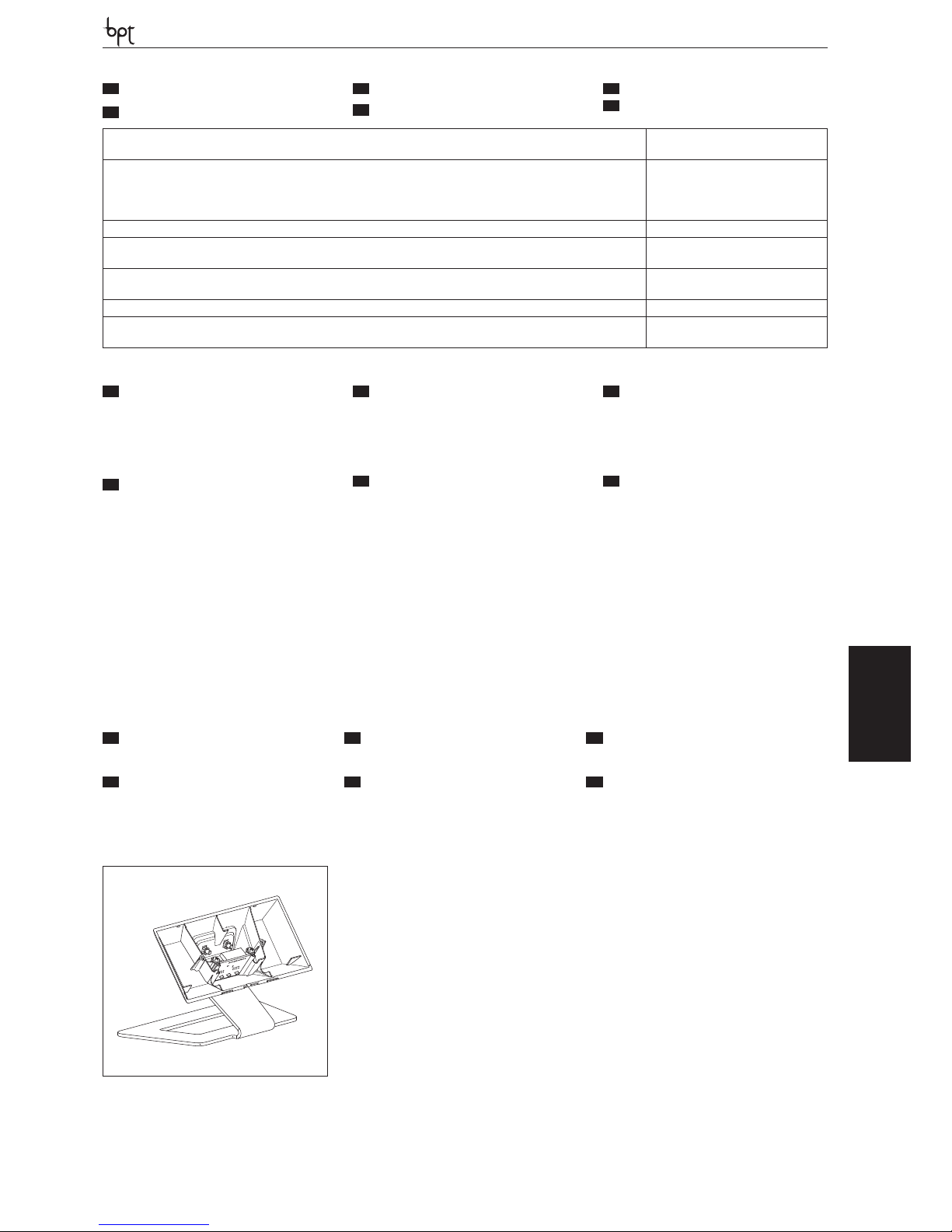
OPHERA LYNEA BASICLYNEANOVAMITHOVAS/100.30
DVC/01
DVC/01 ME
MITHO
Alimentazione locale-Supply voltage local-Stromversorgung örtlichAlimentation local-Alimentación local-Alimentação local
12-16 VAC; 14-24 VDC
Assorbimento-Absorption-StromaufnahmeAbsorption-Consumo-Consumo
12 V AC - 1.5 A (0.75 A stand-by)
16 V AC - 1.1 A (0.5 A stand-by) ,
18 V DC - 0,81 A (0.31 A stand-by)
24 V DC - 0,58 A (0.23 A stand-by) .
Dimensioni-Dimensions-Maße-Dimensions-Dimensiones-Dimensões 203x108x31 mm
Temperatura di stoccaggio-Storage temperature-Lagerungstemperatur
Température de stockage-Temperatura de almacenamiento-Temperatura de armazenagem
-25 °C +70 °C
Temperatura di funzionamento-Operating temperature-Betriebstemperatur
Température de fonctionnement -Temperatura de funcionamiento-Temperatura de funcionamento
5 °C +40 °C
Grado IP-IP Degree-IP-Grad-Degré IP-Grado IP-Grau IP IP 20
Display-Display-Display-Display-Display-Display LCD touch screen
16:9 wide screen 4.3”, 480x272 pixel, .
MHKT
a
IT
CARATTERISTICHE TECNICHE
FR
CARACTÉRISTIQUES TECHNIQUES
EN
TECHNICAL FEATURES
ES
CARACTERÍSTICAS TÉCNICAS
DE
TECHNISCHE MERKMALE
PT
CARACTERÍSTICAS TÉCNICAS
29
IT
MESSA IN SERVIZIO
Per la messa in servizio dei videoterminali consultare il “Manuale Utente” al capitolo “Setup
Tecnico”.
FR
MISE EN SERVICE
Pour la mise en service des portiers vidéo,
consulter le “Manuel Utilisateur” au chapitre
“Conguration Technique”.
EN
COMMISSIONING
For the commissioning of the video terminals,
consult the “User Manual” in the chapter “Ser-
vice Setup”.
ES
PUESTA EN SERVICIO
Para la puesta en servicio de los terminales de
vídeo, consulte el capítulo “Setup Servicio” del
“Manual de Usuario”.
DE
INBETRIEBNAHME
Für die Inbetriebnahme der Videoterminals im
“Benutzerhandbuch” unter Kapitel “Technisches Setup” nachschlagen.
PT
COLOCAÇÃO EM SERVIÇO
Para a colocação em serviço dos terminais de
vídeo consulte o “Manual do Utilizador”,
capítulo “Setup Técnico”.
IT
ACCESSORI
EN
ACCESSORIES
DE
PROGRAMMIERUNG
a Supporto da tavolo MHKT; a MHKT tabletop support; a Tischhalterung MHKT;
FR
ACCESSOIRES
ES
ACCESORIOS
PT
ACESSÓRIOS
a Support de table MHKT; a Soporte de mesa MHKT; a Suporte de mesa MHKT;
Page 30
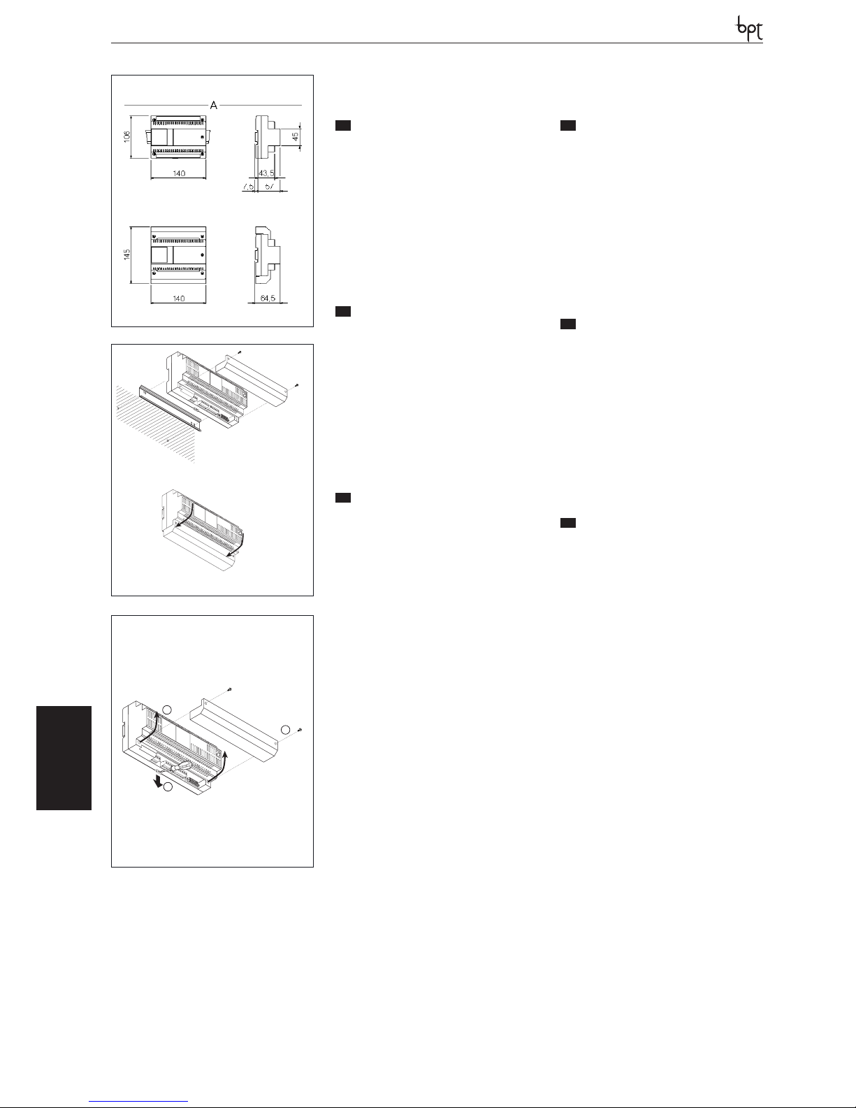
VAS/100.30
OPHERALYNEA BASIC LYNEA NOVA MITHO VAS/100.30
DVC/01
DVC/01 ME
VAS/100.30
30
1
2
2
1
3
3
IT
-
INSTALLAZIONE
• L’alimentatore deve essere installato SEMPRE in orizzontale.
• L’apparecchio è installabile su guida DIN (EN
50022) in un apposito quadro elettrico o a parete utilizzando i coprimorsetti di protezione.
• Per lo smontaggio procedere come indicato in
figura 2-3.
• Per le dimensioni di ingombro vedere le figura 1.
NOTA. Provvedere ad una corretta areazione nel caso l’alimentatore venga installato
in un contenitore metallico.
EN
INSTALLATION
• The power supplier must ALWAYS be installed horizontally.
• The device can be installed on a DIN rail (EN
50022) in an appropriate electric panel or it may
be wall-mounted using the protective terminal
covers.
• For disassembly, proceed as shown in figure 2-3.
• For the overall dimensions see figure 1.
NOTE. Proper ventilation is required if the
power supplier is installed in a metal container.
DE
INSTALLATION
• Das Netzgerät muss IMMER horizontal installiert werden.
• Das Gerät kann auf einer DIN-Schiene (EN 50022)
in einem eigens vorgesehenen Schaltschrank
oder an der Wand mit Klemmendeckeln installiert werden.
• Für die Demontage wie auf der Abbildung 2-3
gezeigt vorgehen.
• Für die Abmessungen siehe die Abbildung 1.
HINWEIS Falls das Netzgerät in einem Metallgehäuse installiert wird, für ausreichende Belüftung sorgen.
FR
INSTALLATION
• L’alimentateur doit TOUJOURS être installé à l’horizontale.
• L’appareil peut être installé sur rail DIN (EN 50022)
dans un tableau électrique prévu à cet effet ou
sur le mur en utilisant les cache-bornes de protection.
• Pour le démontage, procéder comme indiqué à
la figure 2-3.
• Pour les dimensions hors tout, voir la fig. 1.
NOTE. Pourvoir à une correcte aération au
cas où l’alimentateur serait installé dans un
boîtier métallique.
ES
INSTALACIÓN
• El alimentador debe instalarse SIEMPRE en
horizontal.
• El aparato puede instalarse en guía DIN (EN
50022) dentro de un cuadro eléctrico adecuado
o sobre una pared utilizando los cubrebornes de
protección.
• Para el desmontaje, siga las indicaciones de la
figura 2-3.
• Para las medidas necesarias vea la figura 1.
NOTA. Garantice una correcta ventilación si
se instala el alimentador en una caja metálica.
PT
INSTALAÇÃO
• O alimentador deve ser instalado SEMPRE
na horizontal.
• O aparelho pode ser instalado na guia DIN (EN
50022), num quadro eléctrico específico ou na
parede utilizando as tampas dos bornes de protecção.
• Para a desmontagem proceda como indicado na
figura 2-3.
• Para as dimensões totais veja a figura 1.
NOTA. Providencie uma ventilação adequada se o aparelho for instalado numa caixa
metálica.
Page 31
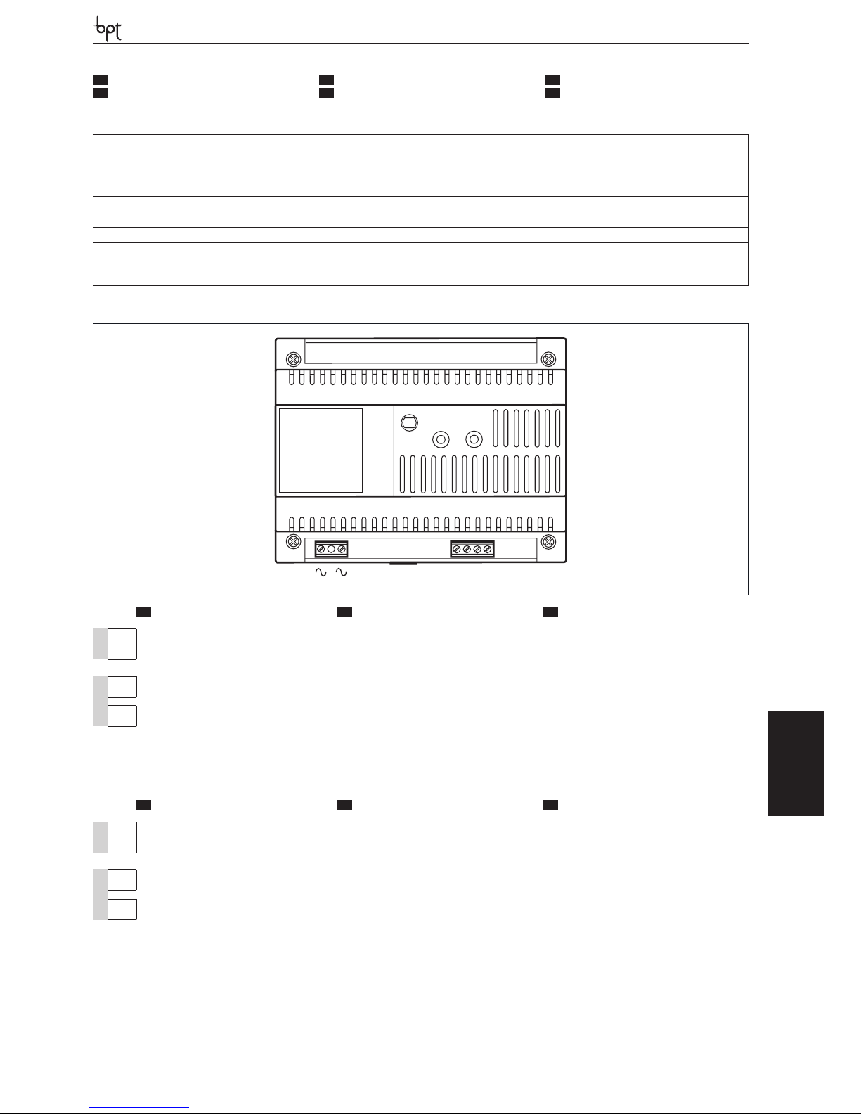
VAS/100.30
OPHERA LYNEA BASICLYNEANOVAMITHOVAS/100.30
DVC/01
DVC/01 ME
31
Alimentazione-Power supply-Stromversorgung Alimentation-Alimentación-Alimentação 230 VAC 50÷60 Hz
Corrente assorbita-Input current-Stromaufnahme Courant absorbé-Corriente absorbida-Corrente consumida
I
max
=250 mA
AC
AC
Potenza dissipata-Dissipated power-Verlustleistung Puissance dissipée-Potencia disipada-Potência dissipada 10 W max
Alimentazione nominale-Nominal power supply-Nennstromversorgung Alimentation nominale-Alimentación nominal-Alimentação nominal 17,5 VDC-1,7 A
Dimensioni-Dimensions-Maße Dimensions-Dimensiones-Dimensões 8 DIN
Temperatura di stoccaggio-Storage temperature-Lagerungstemperatur
Température de stockage-Temperatura de almacenamiento-Temperatura de armazenagem
-25 °C + 70 °C
Temperatura di funzionamento-Operating temperature-Betriebstemperatur Température de fonctionnement -Temperatura de funcionamiento-
Temperatura de funcionamento
0 °C +35 °C
Grado IP-IP Degree-IP-Grad Degré IP-Grado IP-Grau IP IP 30
IT
CARATTERISTICHE TECNICHE
FR
CARACTÉRISTIQUES TECHNIQUES
EN
TECHNICAL FEATURES
ES
CARACTERÍSTICAS TÉCNICAS
DE
TECHNISCHE MERKMALE
PT
CARACTERÍSTICAS TÉCNICAS
1
A
G
2
1
2
IT
MORSETTIERE
EN
TERMINAL BOARDS
DE
KLEMMENBRETTER
G
~
Rete Mains Netz
~
A
1
2
Alimentazione 17,5 VDC (*) Power supply 17,5 VDC (*) Versorgung 17,5 VDC (*)
1
2
Alimentazione 17,5 VDC (*) Power supply 17,5 VDC (*) Versorgung 17,5 VDC (*)
(*) L’apparecchio è protetto elettronicamente
contro sovraccarichi e cortocircuiti.
(*) The appliance is electronically protected
against overloads and short circuits.
(*) Das Gerät ist vor Überlastungen und Kurzschlüssen elektronisch geschützt.
FR
BORNIERS
ES
BORNERAS
PT
RÉGUAS DE BORNES
G
~
Secteur Red
Rede
~
A
1
2
Alimentation 17,5 VDC (*) Alimentación 17,5 VCC (*) Alimentação 17,5 VDC (*)
1
2
Alimentation 17,5 VDC (*) Alimentación 17,5 VCC (*) Alimentação 17,5 VDC (*)
(*) L’appareil est protégé électroniquement
contre les surcharges et les courts-circuits.
(*) El aparato incluye protección electrónica contra sobrecargas y cortocircuitos.
(*) O aparelho está protegido electronicamente
contra sobrecargas e curtos-circuitos.
Page 32
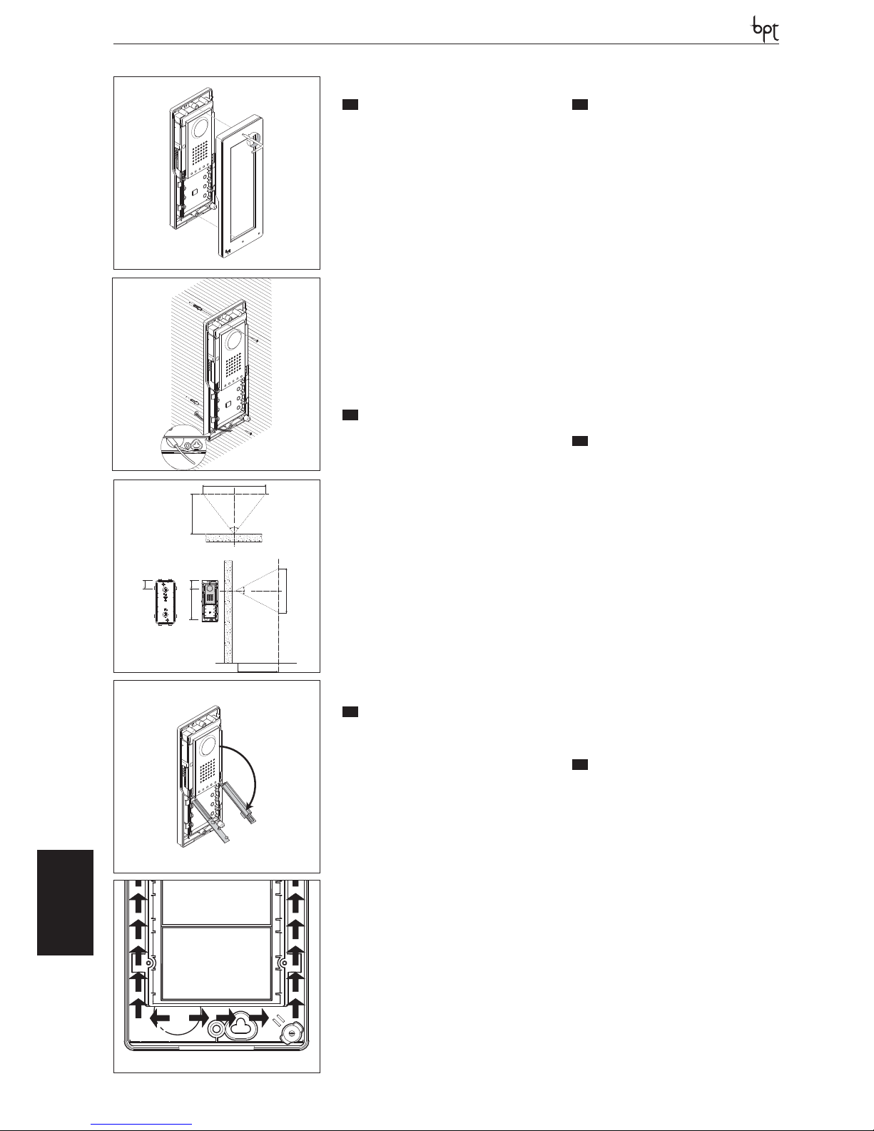
DVC/01-DVC/01 ME
OPHERALYNEA BASIC LYNEA NOVA MITHO VAS/100.30
DVC/01
DVC/01 ME
DVC/01DVC/01 ME
IT
INSTALLAZIONE DA PARETE
• Tramite la chiave a brugola svitare le viti di bloccaggio e togliere la placca (figura 1 - non per
versioni Metal).
• Fissare i tasselli in dotazione e avvitare il posto
esterno (figura 2) all’altezza desiderata tenendo
conto del posizionamento dell’obiettivo della
telecamera (figura 3).
Far passare la tubazione con i conduttori d’im-
pianto come indicato in figura 2.
• Estrarre il coprimorsetto in plastica ed effettuare
i collegamenti (figura 4).
ATTENZIONE. I cavi di collegamento devo-
no essere sguainati no a lo muro e introdotti come indicati in gura 5 (a sinistra i
cavi provenienti dall’alimentatore e a destra quelli relativi alle funzioni di servizio).
• Una volta terminati i collegamenti reinserire i
coprimorsetti.
• Effettuare le operazioni di programmazione e
regolazioni del posto esterno secondo quanto
descritto al capitolo “Programmazione “.
• Montare la placca frontale (figura 1).
EN
WALL MOUNTING
• With the allen wrench unscrew the blocking
screws and remove the plate (figure 1 - not for
Metal versions).
• Fix the given plugs and screw the entry panel
(figure 2) at the desired height considering the
position of the lens of the camera (figure 3).
Run the hose with the system conductors as
shown in figure 2.
• Extract the plastic terminal cover and wire the
connections (figure 4).
WARNING. The connection cables must be
unsheathed ush with the wall and inserted
as indicated in gure 5 (the cables coming
from the power supplier to the left and those
regarding service functions to the right).
• Once all the connections have been made, reinsert the terminal covers.
• Perform the programming and adjustment
operations of the entry panel as described to
the chapter “Programming”.
• Install the front plate (figure 1).
DE
MONTAGE AUFPUTZGEHÄUSE
• Mit dem Inbusschlüssel die Befestigungsschrauben herausdrehen und das Tableau abnehmen
(Abbildung1 - nicht für Metallausführungen).
• Die beiliegenden Dübel befestigen und die
Außenstation unter Berücksichtigung der Objektivstellung der Fernsehkamera (Abbildung
3) in gewünschter Höhe anschrauben (Abbildung 2).
Wie in Abbildung 2 gezeigt, die Rohrleitung
mit den Anlagenleitern durchführen.
• Die Kunststoff-Klemmenabdeckung entfernen
und die Anschlüsse ausführen (Abbildung 4).
ACHTUNG. Die Anschlusskabel müssen bis
zur Wand abgemantelt und wie in der Abbildung 5 gezeigt, eingeführt werden (links
die Kabel des Netzgeräts und rechts die Kabel der Service-Funktionen).
• Nach Abschluss der Anschlussarbeiten die
Klemmenabdeckungen wieder einsetzen.
• Die Außenstation, wie im kapitel “Programmie-im kapitel “Programmie- “Programmierung” beschrieben, programmieren und einstellen.
• Das vordere Tableau montieren (Abbildung 1).
FR
INSTALLATION MURALE
• À l’aide de la clé à six pans, dévisser les vis de
blocage et retirer la plaque (figure 1 - non pour
versions Metal).
• Fixer les chevilles fournies et visser le poste extérieur (figure 2) à la hauteur souhaitée en tenant compte du positionnement de l’objectif
de la caméra (figure 3).
Faire passer la canalisation avec les conduc-
teurs de l’installation comme indiqué à la figure 2.
• Extraire le cache-borne en plastique et effectuer les branchements (figure 4).
ATTENTION. Les câbles de branchement
doivent être sans gaine jusqu’au ras du mur
et introduits comme indiqué à la gure 5 (à
gauche les câbles provenant de l’alimentateur et à droite ceux relatifs aux fonctions
de service).
• Une fois les branchement terminés, réinsérer
les cache-bornes.
• Effectuer les opérations de programmation et
les réglages du poste extérieur comme décrit
au chapitre “Programmation”.
• Monter la plaque frontale (figure 1).
ES
INSTALACIÓN SOBRE PARED
• Usando la llave Allen, desenrosque los tornillos
de fijación y quite la placa (figura 1- no para
versiones Metal).
• Fije los tacos suministrados y atornille la placa
externa (figura 2) a la altura deseada, teniendo
en cuenta la colocación del objetivo de la cámara (figura 3).
Pase el tubo con los conductores de la instala-
ción como se muestra en la figura 2.
• Extraiga el cubreborne de plástico y realice las
conexiones (figura 4).
ATENCIÓN. Los cables de conexión deben
desenfundarse hasta llegar a ras de la pared e introducirse de la manera indicada en
la gura 5 (a la izquierda los cables procedentes del alimentador y a la derecha los
relativos a las funciones de servicio).
• Una vez concluidas las conexiones, vuelva a
colocar los cubrebornes.
• Efectúe las operaciones de programación y
ajustes de la placa externa según se describe
en el capítulo “Programación”.
• Monte la placa frontal (figura 1).
PT
INSTALAÇÃO DE PAREDE
• Com a chave allen desaperte os parafusos de
fixação e extraia a placa (figura 1 - não nas versões Metal).
• Fixe as buchas fornecidas e aparafuse a placa
botoneira (figura 2) à altura desejada tendo
em conta a posição da objectiva da câmara de
vídeo (figura 3).
Passe o tubo com os condutores da instalação
como ilustrado na figura 2.
• Extraia a tampa do borne de plástico e faça as
ligações (figura 4).
ATENÇÃO. Os cabos de ligação têm de ser
descarnados até ao nível da parede e introduzidos como ilustrado na gura 5 (à
esquerda os cabos provenientes do alimentador e à direita os relativos às funções de
serviço).
• Após ter terminado as ligações reinsira as tampas dos bornes.
• Efectue as operações de programação e regulações da placa botoneira segundo o descrito
o capítulo “Programação”.
• Monte a placa frontal (figura 1).
2
1
5
4
500 mm
860 mm
570 mm
500 mm
50 mm
180 mm
65 mm
55°
76°
3
32
Page 33
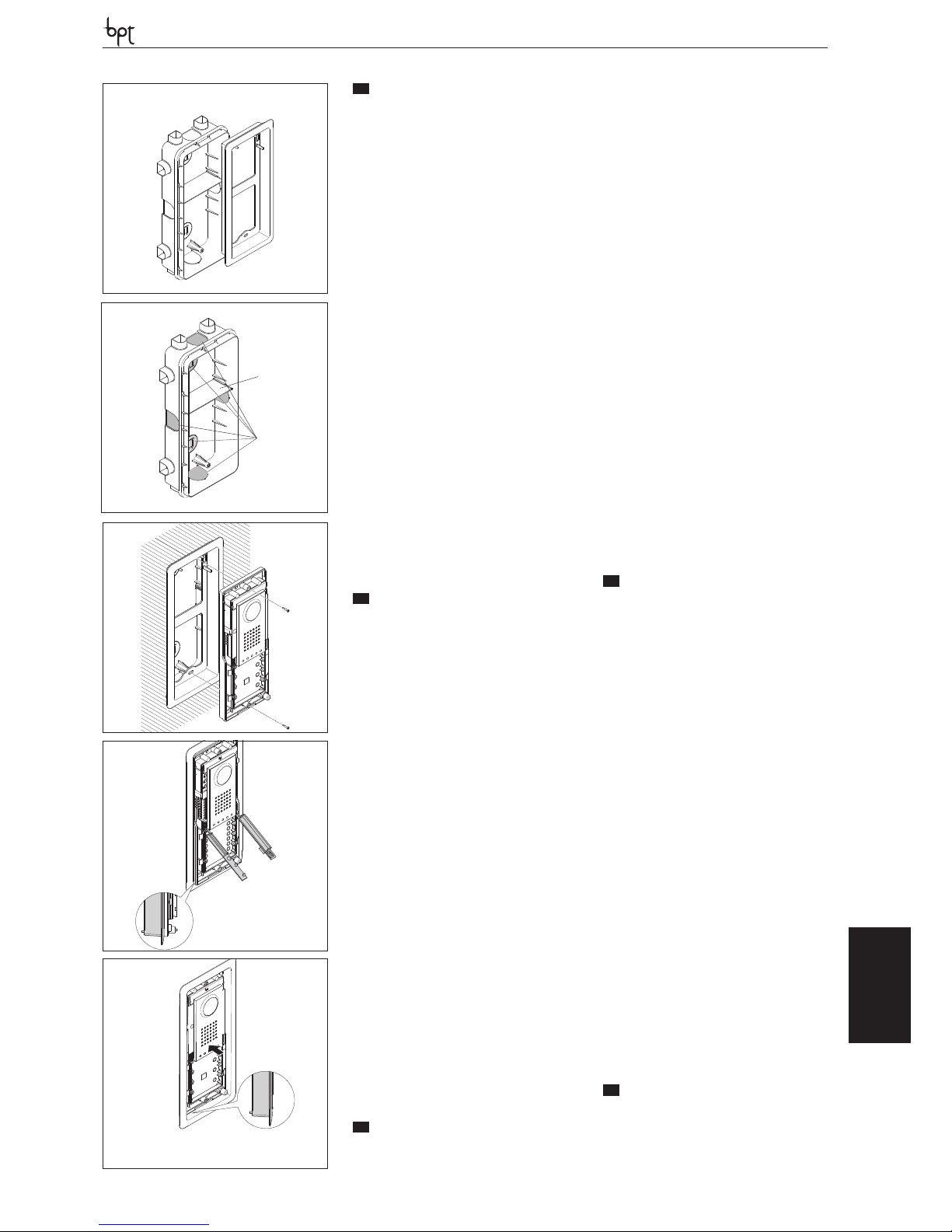
DVC/01-DVC/01 ME
OPHERA LYNEA BASICLYNEANOVAMITHOVAS/100.30
DVC/01
DVC/01 ME
IT
INSTALLAZIONE DA INCASSO
• Murare la scatola d’incasso all’altezza desiderata
tenendo conto del posizionamento dell’obiettivo della telecamera (figura 3) e facendo preventivamente passare la tubazione con i conduttori
d’impianto attraverso uno dei punti a rottura
(figura 7 punto A).
Nella messa in opera della scatola d’incasso si
potranno evitare possibili deformazioni utilizzando l’apposito distanziale in dotazione (figura 7 punto B).
• Tramite la chiave a brugola svitare le viti di bloccaggio e togliere la placca del posto esterno (figura 1 - non per versioni Metal).
• Per facilitare i collegamenti appoggiare la cornice alla scatola d’incasso (figura 8).
• Introdurre i cavi di collegamento nell’apposito
foro e appoggiare il posto esterno sulla cornice
come indicato in figura 8 e fissarlo in posizione
semi-estratta (figura 9 punto 1); estrarre il coprimorsetto in plastica ed effettuare i collegamenti.
ATTENZIONE. I cavi di collegamento devo-
no essere introdotti come indicati in gura
5 (a sinistra i cavi provenienti dall’alimentatore e a destra quelli relativi alle funzione di
servizio).
• Una volta terminati i collegamenti portare a
contatto, tramite una leggera spinta verso l’alto,
il posto esterno alla cornice (figura 10) e reinserire i coprimorsetti (figura 11).
• Effettuare le operazioni di programmazione e
regolazioni del posto esterno secondo quanto
descritto al capitolo “Programmazione “.
• Montare la placca frontale (figura 1).
EN
RECESSED INSTALLATION
• Install the recessed box at the desired height
considering the position of the lens of the
camera (figure 3), but in advance, run the hose
with the system conductors through one of
the breaking points (figure 7 point A).
• During installation of the recessed box it is possible to avoid any deformation by using the provided spacer (figure 7 point B).
• With the allen wrench unscrew the blocking
screws and remove the entry panel plate (figure 1 - non for Metal versions).
• To facilitate the connections, lay the frame on
the built-in box.(figure 8).
• Introduce the cable connections in the special
hole and lay the entry panel on the frame as
shown in figure 8 and fix it in a semi-extract
position (figure 9 point 1); extract the plastic
terminal cover and wire the connections.
WARNING. The connection cables must be
inserted as indicated in gure 5 (the cables
coming from the power supplier to the left
and those regarding service functions to
the right).
• Once the connections have been made bring
into contact, by gently pushing upwards, the
entry panel and the frame (figure 10) and reinsert the terminal covers (figure 8).
• Perform the programming and adjustment
operations of the entry panel as described to
the chapter “Programming”.
• Install the front plate (figure 1).
DE
UNTERPUTZMONTAGE
• Den Unterputzkasten unter Berücksichtigung der
Objektivstellung der Fernsehkamera (Abbildung
3) in der gewünschten Höhe einbauen, zuvor die
Rohrleitung mit den Anlagenleitern durch einen
der Ausbrechpunkte (Abb. 7 Punkt A) ziehen.
Beim Einsetzen des Unterputzkastens können
Verformungen vermieden werden, wenn man
den beiliegenden Abstandshalter (Abb. 7 Punkt
B) benutzt.
• Mit dem Inbusschlüssel die Befestigungsschrauben herausdrehen und das Tableau der
Außenstation abnehmen (Abbildung1 - nicht
für Metallausführungen).
• Um die Anschlussarbeiten zu erleichtern, den
Abdeckrahmen auf dem Unterputzkasten ablegen (Abb. 8).
• Die Anschlusskabel durch die Aussparung
ziehen und die Außenstation, wie in der Abbildung 8 gezeigt, auf dem Abdeckrahmen
ablegen und in halb ausgezogener Stellung
befestigen (Abb. 9 Punkt 1); die Klemmenabdeckung aus Kunststoff herausziehen und die
Anscxhlüsse ausführen.
ACHTUNG. Die Anschlusskabel müssen,
wie in der Abbildung 5 gezeigt, eingeführt
werden (links die Kabel des Netzgeräts und
rechts die Kabel der Service-Funktionen).
• Nach den abgeschlossenen Anschlussarbeiten
die Außenstation mit einem leichten Schub
nach oben mit dem Rahmen (Abb. 10) in Berührung bringen und die Klemmenabdeckungen (Abbildung 8) wieder einsetzen.
• Die Außenstation, wie im kapitel “Programmie-im kapitel “Programmie- “Programmierung” beschrieben, programmieren und einstellen.
• Das vordere Tableau montieren (Abb. 1).
FR
INSTALLATION À ENCASTRER
• Murer le boîtier à encastrer à la hauteur souhaitée en tenant compte du positionnement de
l’objectif de la caméra (figure 3) et en faisant
préalablement passer la canalisation avec les
conducteurs de l’installation à travers un des
points de rupture (figure 7 point A).
Lors de la mise en place du boîtier à encastrer,
éviter de possibles déformations en utilisant la
douille fournie et prévue à cet effet (figure 7
point B).
• À l’aide de la clé à six pans, dévisser les vis de blocage et retirer la plaque du poste extérieur (figure
1 - non pour versions Metal).
• Pour faciliter les branchements, poser le cadre
sur le boîtier à encastrer (figure 8).
• Introduire les câbles de branchement dans le
trou prévu à cet effet, poser le poste extérieur
sur le cadre comme indiqué à la figure 8 et le
fixer en position semi-extraite (figure 9 point 1)
; extraire le cache-borne en plastique et effectuer les branchements.
ATTENTION. Les câbles de branchement
doivent être introduits comme indiqué à la
gure 5 (à gauche les câbles provenant de
l’alimentateur et à droite ceux relatifs aux
fonctions de service).
• Une fois terminés les branchements mettre en
contact, en poussant légèrement vers le haut,
le poste extérieur et le cadre (figure 10) et réinsérer les cache-bornes (figure 8).
• Effectuer les opérations de programmation et
les réglages du poste extérieur comme décrit
au chapitre “Programmation”.
• Monter la plaque frontale (figure 1).
ES
INSTALACIÓN EMPOTRADA
• Empotre la caja a la altura deseada teniendo en
cuenta la colocación del objetivo de la cámara
(figura 3), tras pasar el tubo con los conductores de la instalación a través de uno de los
orificios precortados (figura 7 punto A).
A
B
7
6
10
9
8
2
2
1
33
Page 34
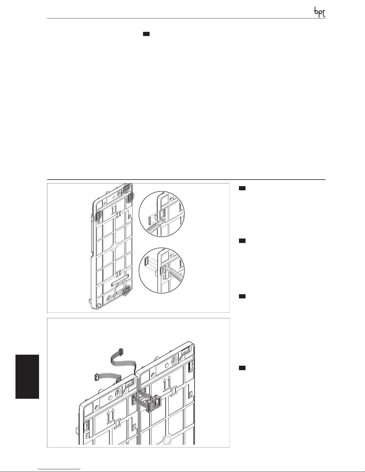
DVC/01-DVC/01 ME
OPHERALYNEA BASIC LYNEA NOVA MITHO VAS/100.30
DVC/01
DVC/01 ME
Durante la instalación de la caja empotrable se
podrán evitar posibles deformaciones utilizando
el distanciador suministrado (fi gura 7 punto B).
• Usando la llave Allen, desenrosque los tornillos de
fi jación y quite la placa de la placa externa (fi gura
1 - no para versiones Metal).
• Para facilitar las conexiones, apoye el marco
contra la caja empotrable (fi gura 8).
• Introduzca los cables de conexión por el orifi cio
correspondiente, apoye la placa externa contra
el marco, como se muestra en la fi gura 8, y fíjela en posición semi-extraída (fi gura 9 punto
1); quite el cubreborne de plástico y efectúe las
conexiones.
ATENCIÓN. Los cables de conexión deben in-
troducirse de la manera indicada en la gura
5 (a la izquierda los cables procedentes del
alimentador y a la derecha los relativos a las
funciones de servicio).
• Una vez concluidas las conexiones, ponga en contacto, empujando ligeramente hacia arriba, la placa externa y el marco (fi gura 10) y vuelva a colocar
los cubrebornes (fi gura 8).
• Efectúe las operaciones de programación y
ajustes de la placa externa según se describe
en el capítulo “Programación”.
• Monte la placa frontal (fi gura 1).
IT
AFFIANCABILITÀ A PARETE
• I posti esterni possono essere affi ancati sia in
orizzontale che in verticale.
• Rimuovere per mezzo di un cutter i particolari
plastici dalle basi dei posti esterni (fi gura 11)
• Far passare i cavetti di connessione fra i le basi
dei posti esterni (fi gure 12), avendo cura di seguire la sequenza indicata in fi gura 13 e 14.
EN
SIDEBYSIDE WALL
INSTALLATION
• Entry panels can be placed side-by-side both
horizontally and vertically.
• Using a cutter, remove the plastic details of the
entry panel bases (fi gure 11)
• Run the connection wires between the entry
panel bases (fi gure 12), ensuring to follow the
sequence indicated in fi gure 13 and 14.
DE
ANEINANDERREIHEN BEI
AUFPUTZMONTAGE
• Die Außenstationen können durch das Ineinanderstecken der Gehäuse sowohl horizontal
als auch vertikal.
• Mit Hilfe eines Cutters die Kunststoff teile von
den Unterteilen der Außenstationen entfernen
(Abbildung 11)
• Die Verbindungskabel zwischen den Unterteilen der Außenstationen (Abbildungen 12)
durchführen, dabei auf die in Abbildung 13
und 14 gezeigte Reihenfolge achten
FR
JUXTAPOSITION MURALE
• Les postes extérieurs peuvent être juxtaposés
aussi bien en horizontal.
• Retirer à l’aide d’un cutter les parties en plastique des bases des postes extérieurs (fi gura
11)
• Faire passer les câbles de connexion entre les
bases des postes extérieurs (fi gure 12), en suivant bien la séquence indiquée à la fi gure 13 et
14.
PT
INSTALAÇÃO DE EMBUTIR
• Monte a caixa de embutir na parede à altura
desejada tendo em conta a posição da objectiva da câmara de vídeo (fi gura 3) e passando
previamente o tubo com os condutores de instalação através de um dos pontos de ruptura
(fi gura 7 ponto A).
Ao instalar a caixa de embutir podem-se evitar
possíveis deformações utilizando o específi co
espaçador fornecido (fi gura 7 ponto B).
• Com a chave allen desaperte os parafusos de
fi xação e extraia a placa da placa botoneira (fi gura 1 - não nas versões Metal).
• Para facilitar as ligações apoiar a moldura na
caixa de encastre (fi gura 8).
• Introduzir os cabos de ligação no furo apropriado e apoiar a placa botoneira externa na
moldura como indicado na fi gura 8 e fi xá-la na
posição semi-extraída (fi gura 9 item 1); extrair
a cobertura do borne em plástico e efectuar as
ligações.
ATENÇÃO. Os cabos de ligação têm de ser
introduzidos como ilustrado na gura 5 (à
esquerda os cabos provenientes do alimentador e à direita os relativos às funções de
serviço).
• Após ter terminado as ligações coloque em
contacto, com uma leve pressão para cima, a
placa botoneira com a moldura (fi gura 10) e
reinsira as tampas dos bornes (fi gura 8).
• Efectue as operações de programação e regulações da placa botoneira segundo o descrito
o capítulo “Programação”.
• Monte a placa frontal (fi gura 1).
1
2
11
12
34
Page 35
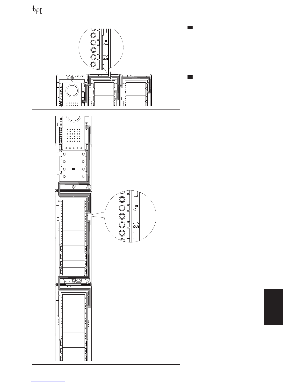
DVC/01-DVC/01 ME
OPHERA LYNEA BASICLYNEANOVAMITHOVAS/100.30
DVC/01
DVC/01 ME
ES
INSTALACIÓN CONTIGUA
SOBRE PARED
• Las placas externas se pueden instalar contiguamente tanto en horizontal como en vertical.
• Quite con un cutter los elementos plásticos de
las bases de las placas externas (figura 11)
• Pase los cables de conexión entre las bases de
las placas externas (figura 12), asegurándose
de seguir el orden indicado en la figura 13 y 14.
PT
MONTAGEM LADO A LADO
DE PAREDE
• As placas botoneiras podem ser montadas
lado a lado quer na horizontal quer na vertical.
• Remova com um x-ato os detalhes em plástico
das bases das placas botoneiras (figura 11)
• Passe os cabos de conexão entre as bases das
placas botoneiras (figuras 12), tendo o cuidado
de seguir a sequência indicada na figura 13 e
14.
CN4
CN1
CN1
CN2
CN4
CN1
CN2
CN1
13
14
35
Page 36
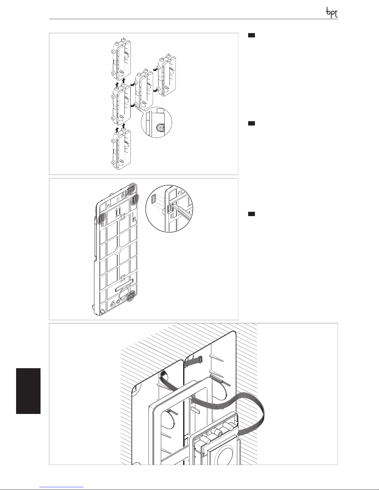
DVC/01-DVC/01 ME
OPHERALYNEA BASIC LYNEA NOVA MITHO VAS/100.30
DVC/01
DVC/01 ME
IT
AFFIANCABILITÀ A INCASSO
• I posti esterni possono essere affi ancati sia in
orizzontale che in verticale (fi gura 15) incastrando tra di loro le scatole.
• Prima di murare le stesse provvedere a spaccare
i punti a rottura inferiore o laterale come evidenziato in fi gura 15 (punto A) per poter far passare
il cavo di connessione dal posto esterno pulsanti
al posto esterno principale/precedente.
• Rimuovere per mezzo di un cutter i particolari
plastici dalle basi dei posti esterni (fi gura 16).
• Far passare i cavetti di connessione fra i le basi
dei posti esterni avendo cura di seguire la sequenza indicata in fi gura 17.
EN
SIDEBYSIDE RECESSED
INSTALLATION
• Entry panels can be placed side-by-side both
horizontally and vertically (fi gure 15) locking
the boxes with one another.
• Before installing them, break the lower and
side breaking points as highlighted in fi gure 15
(point A) in order to run the connection cable
from the push button entry panel to the main/
previous entry panel.
• Using a cutter, remove the plastic details of the
entry panel bases (fi gure 16)
• Run the connection wires between i the entry
panel bases ensuring to follow the sequence
indicated in fi gure 17.
DE
ANEINANDERREIHEN BEI
UNTERPUTZMONTAGE
• Die Außenstationen können durch das Ineinanderstecken der Gehäuse sowohl horizontal
als auch vertikal (Abbildung 15) aneinandergereiht werden.
• Vor dem Einmauern derselben müssen, wie in
Abbildung 15 (Punkt A) gezeigt, die unteren
oder seitlichen Ausbrechpunkte geöff net werden, um das Verbindungskabel von der Tastenaußenstation zur Hauptaußenstation oder
vorherigen Station durchziehen zu können.
• Mit Hilfe eines Cutters die Kunststoff teile von
den Unterteilen der Außenstationen entfernen
(Abbildung 16).
• Die Verbindungskabel zwischen den Unterteilen der Außenstationen durchführen, dabei
auf die in Abbildung 17 gezeigte Reihenfolge
achten.
A
15
16
17
36
Page 37
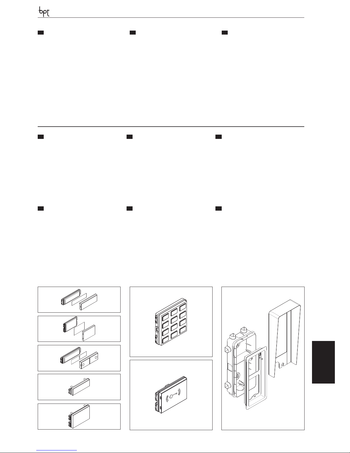
DVC/01-DVC/01 ME
OPHERA LYNEA BASICLYNEANOVAMITHOVAS/100.30
DVC/01
DVC/01 ME
FR
JUXTAPOSITION À
ENCASTREMENT
• Les postes extérieurs peuvent être juxtaposés
aussi bien en horizontal qu’en vertical (figure
15) en encastrant entre eux les boîtiers.
• Avant de les murer, rompre les points de rupture inférieur ou latéral comme mis en évidence à la figure 15 (point A) afin de pouvoir
faire passer le câble de connexion du poste
extérieur boutons au poste extérieur principal/
précédent.
• Retirer à l’aide d’un cutter les parties en plastique des bases des postes extérieurs (figura
16).
• Faire passer les câbles de connexion entre les
bases des postes extérieurs en suivant bien la
séquence indiquée à la figure 17.
ES
INSTALACIÓN CONTIGUA
EMPOTRAD
• Las placas externas se puede instalar contiguamente tanto en horizontal como en vertical (figura 15), encajando las cajas entre sí.
• Antes de empotrarlas, traspase los orificios precortados inferiores o laterales como se muestra
en la figura 15 (punto A) para poder pasar el
cable de conexión desde la placa externa de
botones a la placa externa principal/anterior.
• Quite con un cutter los elementos plásticos de
las bases de las placas externas (figura 16)
• Pase los cables de conexión entre las bases de las
placas externas, asegurándose de seguir el orden
indicado en la figura 17.
PT
MONTAGEM LADO A LADO
DE EMBUTIR
• As placas botoneiras podem ser montadas
lado a lado quer na horizontal quer na vertical
(figura 15) encaixando as caixas entre si.
• Antes de as instalar na parede parta os pontos
de ruptura inferior ou lateral, como ilustrado na
figura 15 (ponto A), para poder passar o cabo
de conexão da placa botoneira botões à placa
botoneira principal/anterior.
• Remova com um x-ato os detalhes em plástico
das bases das placas botoneiras (figura 16).
• Passe os cabos de conexão entre as bases das
placas botoneiras, tendo o cuidado de seguir a
sequência indicada na figura 17.
a
c
d
e
DSI
DCI
DCI ME
h
i
j
DTP
f
g
DRFID
DNADNA ME
37
DPS
b
DPH
DPD
DTSDTS ME
DTHDTH ME
IT
ACCESSORI
EN
ACCESSORIES
DE
ZUBEHÖR
- Pulsante singolo a DPS e doppia altezza b
DPH,
- Pulsante doppio DPD c,
- Tappo altezza singola d DTS (DTS ME) e doppia
e DTH (DTH ME),
- Modulo controllo accessi con tastiera f DNA
(DNA ME),
- Modulo controllo accessi con lettore RFID g DR-
FID,
- Scatola d’incasso DSI h,
- Cornice da incasso DCI (DCI ME) i,
- Tettuccio da parete DTP j.
- DPS single button a and double height b DPH,
- Double DPD button c,
- Single height plug d DTS (DTS ME) and double
e DTH (DTH ME),
- Access control module with keyboard f DNA
(DNA ME),
- Access control module with RFID reader g DRFID,
- Recessed box DSI h,
- Recessed frame DCI (DCI ME) i,
- Wall roof DTP j.
- Einzeltaste a DPS und Doppelte höhe b DPH,
- Doppeltaste DPD c,
- Deckel Einzelhöhe d DTS (DTS ME) und doppelte Höhe e DTH (DTH ME),
- Zutrittskontrollmodul mit Tastatur f DNA (DNA
ME),
- Zutrittskontrollmodul mit Lesegerät RFID g
DRFID,
- Unterputzkasten DSI h,
- Unterputzrahmen DCI (DCI ME) i,
- Dach für wandmontage DTP j.
FR
ACCESSOIRES
ES
ACCESORIOS
PT
ACESSÓRIOS
- Bouton simple a DPS et hauteur double b
DPH,
- Bouton double DPD c,
- Bouchon hauteur simple d DTS (DTS ME)et
double e DTH (DTH ME),
- Module de contrôle des accès avec clavier f
DNA (DNA ME),
- Module de contrôle des accès avec lecteur RFID
g DRFID,
- Boîtier à encastrer DSI h,
- Cadre pour encastrement DCI (DCI ME) i,
- Visière de protection murale DTP j.
- Botón único a DPS y de doble altura b DPH,
- Botón doble DPD c,
- Tapón altura única d DTS (DTS ME) y doble e
DTH (DTH ME),
- Módulo de control de accesos con teclado f
DNA (DNA ME),
- Módulo de control de accesos con lector RFID g
DRFID,
- Caja empotrable DSI h,
- Marco empotrable DCI (DCI ME) i,
- Visera de superficie DTP j.
- Botão simples a DPS (DPS ME) e de dupla altura
b DPH (DPH ME),
- Módulo botão duplo DPD c,
- Tampa altura simples d DTS (DTS ME) e dupla e
DTH (DTH ME),
- Módulo controlo acessos com teclado f DNA
(DNA ME),
- Módulo controlo acessos com leitor RFID g DRFID,
- Caixa de embutir DSI h,
- Moldura de embutir DCI (DCI ME) i,
- Tecto de parede j.
Page 38
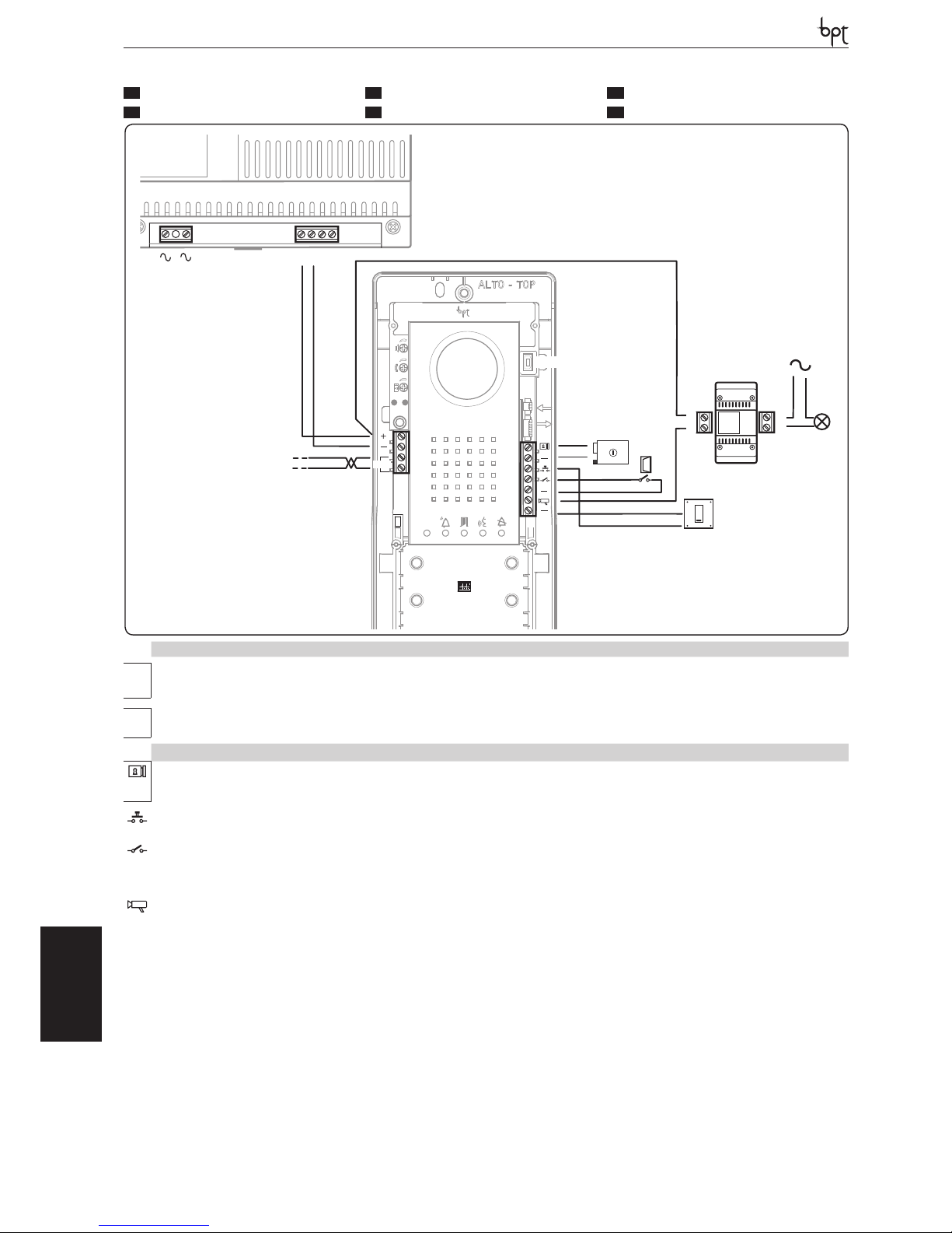
DVC/01-DVC/01 ME
OPHERALYNEA BASIC LYNEA NOVA MITHO VAS/100.30
DVC/01
DVC/01 ME
1
G
2
1
2
M1
CN1
CN4
M2
CN2
PROG
DATI
MINI USB
IN
OUT
VLS/101
1
2
1
2
BOUT
DVC/01
DVC/01 ME
VAS/100.30
Connettori Connectors Steckverbinder Connecteurs Conectores Conectores
CN1: Connettore per
retroilluminazione della cornice del posto
esterno.
CN1: Connector for
backlighting the entry
terminal frame.
CN1: Steckverbinder
für die Hintergrundbeleuchtung des Rahmens der Außenstation.
CN1 : Connecteur pour
rétroéclairage du cadre
du poste extérieur
CN1: Conector para retroiluminación del marco de la placa exterior.
CN1: Conector para
retroiluminação da
moldura da placa botoneira.
CN2: Connettore per il
modulo controllo accessi a tastiera o RFID.
CN2: Connector for the
keyboard or RFID access control module.
CN2: Steckverbinder
für das Zutrittskontrollmodul mit Tastatur
oder RFID.
CN2 : Connecteur pour
le module de contrôle
des accès à clavier ou
RFID.
CN2: Conector para
el módulo de control
de accesos a teclado o
RFID.
CN2: Conector para o
módulo de controlo
dos acessos com teclado ou RFID.
CN4: Connettore per
pulsantiera aggiuntiva.
CN4: Additional push
button panel connector.
CN4: Steckverbinder
für Zusatz-Tastenfeld.
CN4 : Connecteur pour
platine supplémentaire.
CN4: Conector para botonera adicional.
CN4: Conector para botoneira adicional.
MINI USB: Connettore
di programmazione.
MINI USB: Programming connector.
MINI USB: Steckverbinder
für die Programmierung.
MINI USB : Connecteur
de programmation.
MINI USB: Conector de
programación.
MINI USB: Conector de
programação.
Morsettiera M1 Terminal block M1 Klemmenbrett M1 Bornier M1 Bornera M1 Régua de bornes M1
+
Alimentazione 14-18
VDC
Power supply 14-18 VDC
Stromversorgung 14-18
VDC
Alimentation 14-18 VDC Alimentación 14-18 VCC
Alimentação 14-18
VDC
–
BOUT
Montante Busbar Trägerleitung Montant Bajante Coluna
Morsettiera M2 Terminal block M2 Klemmenbrett M2 Bornier M2 Bornera M2 Régua de bornes M2
Elettroserratura
12 V - 1 A max
Solenoid lock
12 V - 1 A max
Elektroschloss
12 V - 1 A max
Gâche électrique
12 V - 1 A max
Cerradura eléctrica
12 V - 1 A max
Fechadura eléctrica
12 V - 1 A max
–
Pulsante apriporta (NA)
Door lock release button (NA)
Türöffnertaste
(NO)
Bouton ouvre-porte
(NO)
Botón abrepuerta (
NA)
Botão de abertura da
porta (NA)
Ingresso contatto porta (NC)
Door contact input
(NC)
Eingang potentialfreier
Kontakt (NC)
Entrée contact porte
(NF)
Entrada contacto puerta (NC)
Entrada contacto porta
(NC)
– Massa Earth Masse Masse Masa Massa
Uscita abilitazione posto esterno (attiva verso massa)
Entry panel enabling
output (active towards
earth)
Ausgang Einschaltung
der Außenstation (aktiv
gegen Masse)
Sortie habilitation poste extérieur (active
vers masse)
Salida habilitación placa exterior (activa hacia
masa)
Saída habilitação placa
botoneira (activa na direcção massa)
– Massa Earth Masse Masse Masa Massa
IT
FUNZIONE DEI MORSETTI
EN
TERMINAL FUNCTION
DE
BELEGUNG DER KLEMMLEISTEN
FR
FONCTIONS DES BORNES
ES
FUNCIÓN DE LOS BORNES
PT
FUNÇÃO DOS BORNES
38
Page 39
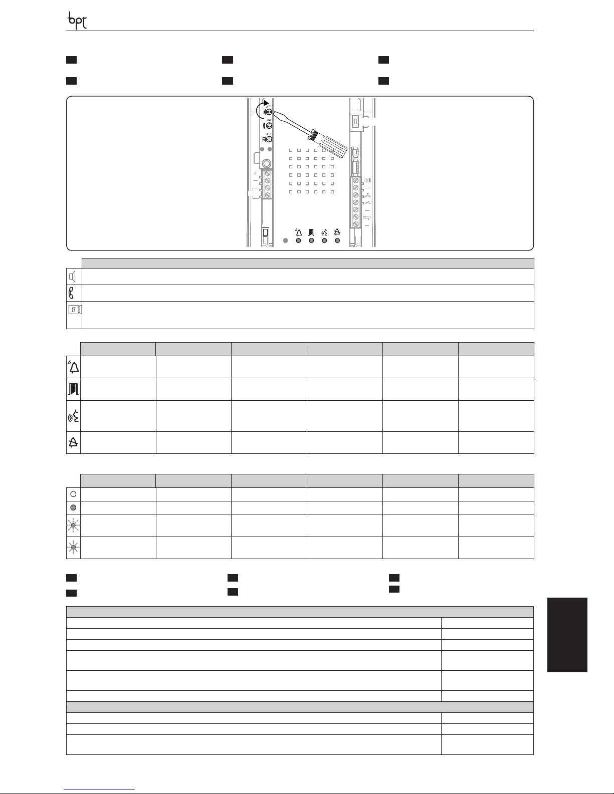
DVC/01-DVC/01 ME
OPHERA LYNEA BASICLYNEANOVAMITHOVAS/100.30
DVC/01
DVC/01 ME
M1
CN1
CN4
M2
PROG
DATI
BOUT
MINI USB
Regolazioni Adjustments Einstellungen Réglages Regulaciones Regulações
audio altoparlante loudspeaker audio Audio Lautsprecher audio haut-parleur audio altavoz áudio altifalante
audio microfono microphone audio Audio Mikrofon audio micro audio micrófono áudio microfone
elettroserratura 1÷10 s.
(default 1 s)
solenoid lock 1-10 s.
(default 1 s)
Elektroschloss 1÷10 s.
(Default 1 s)
gâche électrique 1÷10
s.
(défaut 1 s)
cerradura eléctrica 1÷10
s. (por defecto1 s)
fechadura eléctrica de 1
a 10 seg. (default 1 seg.)
Segnalazioni Signals Anzeigen Signalisations Indicaciones Sinalizações
Rosso
Chiamata in corso
Red
Call in progress
Rot
Ruf im Gange
Rouge
Appel en cours
Rojo
Llamada en curso
Vermelho
Chamada em curso
Verde
Porta aperta
Green
Door open
Grün
Tür off en
Vert
Porte ouverte
Verde
Puerta abierta
Verde
Porta aberta
Giallo
Conversazione in
corso
Yellow
Conversation in
progress
Gelb
Konversation im
Gange
Jaune
Conversation en cours
Amarillo
Conversación en curso
Amarelo
Conversa em curso
Blu
Impianto occupato
Blue
System busy
Blau
Leitung besetzt
Bleu
Installation occupée
Azul
Instalación ocupada
Azul
Instalação ocupada
Simbologia LED LED symbology LED-Zeichen Symboles LED Signi cado LED Símbolos dos LEDs
Spento Off Aus Éteint Apagado Apagado
Acceso On An Allumé Encendido Aceso
Lampeggio lento Slow fl ashing Langsames Blinken Clignotement lent Parpadeo lento Intermitente lento
Lampeggio veloce Quick fl ashing Schnelles Blinken Clignotement rapide Parpadeo rápido Intermitente rápido
Posto esterno-Entry panel-Außenstation-Poste extérieur-Placa exterior-Placa botoneira
Alimentazione-Power supply-Stromversorgung-Alimentation-Alimentación-Alimentação 14-18 VDC
Assorbimento-Absorption-Stromaufnahme-Absorption-Consumo-Consumo 320 mA (130mA stand-by)
Dimensioni-Dimensions-Maße-Dimensions-Dimensiones-Dimensões 99x254x25 mm
Temperatura di stoccaggio-Storage temperature-Lagerungstemperatur
Température de stockage-Temperatura de almacenamiento-Temperatura de armazenagem
-25 °C +70 °C
Temperatura di funzionamento-Operating temperature-Betriebstemperatur
Température de fonctionnement -Temperatura de funcionamiento-Temperatura de funcionamento
-15 °C +50 °C
Grado IP-IP Degree-IP-Grad-Degré IP-Grado IP-Grau IP IP 54
Telecamera-Camera-Telekamera-Caméra-Cámara-Câmara de vídeo
Standard video-Standard video-Videostandard-Standard vidéo-Estándar de vídeo-Standard vídeo PAL/NTSC
Risoluzione-Resolution-Au ösung-Résolution-Resolución-Resolução 680x512 pixel
Illuminazione minima-Minimum lighting-Mindestbeleuchtung
Éclairage minimal-Iluminación mínima-Iluminação mínima
1 LUX
IT
REGOLAZIONI E FUNZIONI
DEI LED
EN
LED FUNCTIONS AND
ADJUSTMENTS
DE
EINSTELLUNGEN UND
FUNKTIONEN DER LEDS
FR
RÉGLAGES ET FONCTIONS
DES LEDS
ES
AJUSTES Y FUNCIONES DE LOS
LEDS
PT
REGULAÇÕES E FUNÇÕES DOS
LEDS
IT
CARATTERISTICHE TECNICHE
FR
CARACTÉRISTIQUES TECHNIQUES
EN
TECHNICAL FEATURES
ES
CARACTERÍSTICAS TÉCNICAS
DE
TECHNISCHE MERKMALE
PT
CARACTERÍSTICAS TÉCNICAS
39
Page 40
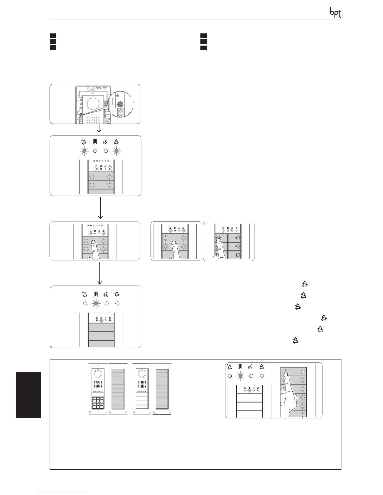
DVC/01-DVC/01 ME
OPHERALYNEA BASIC LYNEA NOVA MITHO VAS/100.30
DVC/01
DVC/01 ME
Prima programmazione
Initial programming
Erstprogrammierung
Première programmation
Primera programación
Primeira programação
Ingresso in Programmazione. Premere per almeno 3 s il tasto PROG a e rilascire entro 6 s. L’eventuale spegnimento immediato del Led
PROG segnala un malfunzionamento. Veri care le connessioni e rientrare in programmazione. I led dei posti esterni si accenderanno come illustrato
in gura b. Attendere 5 secondi la conclusione dell’autotest e proseguire come sotto indicato.
Accessing programming. Press the PROG key a for at least 3 sec and then release it within 6 s. If the PROG LED turns o suddenly, this indicates
a malfunction. Check the connections and return to programming. The entr y panel LEDs turn on as shown in the gure b. Wait 5 seconds for the
self-test to be completed and then continue as described below.
Einstieg in die Programmierung. Für mindestens 3 s die Taste PROG a drücken und innerhalb 6 s loslassen. Ein eventuelles sofortiges
Ausschalten der Led PROG zeigt. Die Anschlüsse prüfen und wieder in die Programmierung einsteigen. Die Leds der Außenstationen leuchten auf,
wie auf der Abbildung b dargestellt. 5 Sekunden bis zum Ende des Autotests warten und danach wie folgt vorgehen.
Entrée en Programmation. Appuyer pendant au moins 3 s sur la touche PROG a et relâche dans les 6 s. L’éventuelle extinction immédiate de la
Led PROG signale un dy sfonctionnement. Contrôler les connexions et rentrer dans programmation. Les leds des postes extérieurs s’allumeront comme
illustré à la gure b. Attendre pendant 5 secondes la conclusion de l’autotest et continuer comme indiquÈ ci-dessous.
Entrada en la modalidad de Programación. Pulse durante al menos 3 s el botón PROG a y suéltelo antes de 6 s. Si el Led PROG se
apaga inmediatamente, signi ca que hay algún problema de funcionamiento. Compruebe las conexiones y vuelva a entrar en la modalidad de
programación. Los leds de las placas exteriores se encenderán como se muestra en la gura b. Espere 5 segundos la conclusión de la prueba
automática y prosiga como se indica más abajo.
Entrar na Programação Prima durante pelo menos 3 seg. a tecla PR OG a e solte-a dentro de 6 seg. O eventual apagamento imediato do Led
PROG sinaliza uma anomalia no funcionamento. Veri que as conexões e entre novamente na programação. Os leds das placas botoneiras acendem-se
como ilustrado na gura b. Espere 5 segundos para a conclusão do auto teste e continue como indicado a seguir.
d
b
Programmazione del Tipo dei Tasti. Premere il primo tasto del posto esterno c/cA/cB nchè il led
smetterà di lampeggiare
così come i led della retroilluminazione d.
Programming key t ype and address. Press the rst key on the entry terminal c/cA/cB until the LED stops fl ashing as does the
backlighting LEDs d.
Programmierung der Tastenart. Die erste Taste der Außenstation c/cA/cB drücken, bis das Led und die Leds der Hintergrund-
beleuchtung d zu blinken aufhören.
Programmation du Type des Touches. Appuyer sur la première touche du poste extérieur c/cA/cB jusqu’à ce que la led arrêtera de
clignoter ainsi que les leds du rétroéclairage d.
Programación del Tipo de los Botones. Pulse el primer botón de la placa exterior c/cA/cB hasta que el led
y los leds de
retroiluminación dejen de parpadear d.
Programação do Tipo de Teclas. Carregue na primeira tecla da placa botoneira c/cA/cB até o led
deixar de piscar, tal como os leds
da retroiluminação d.
a
PROG
CN1
CN4
B
B
1 2ON3
IN
OUT
PROG
DC/01DC/01 MEDVC/01DVC/01 ME
>3’’
<6’’
IT
PROGRAMMAZIONE
EN
PROGRAMMING
DE
PROGRAMMIERUNG
FR
PROGRAMMATION
ES
PROGRAMACIÓN
PT
PROGRAMAÇÃO
� Nel caso in cui i tasti di chiamata fossero presenti SOLO SULLE PULSANTIERE AGGIUNTIVE, l’operazione illustrata in gura c va eseguita su di esse come illustrata in gura cC.
- In the case that the call buttons are ONLY located on the ADDITIONAL PUSH BUTTON PANELS, the operation illustrated in gure c must be carried out as illustrated in gure cC.
� Falls die Ruftasten NUR AUF DEN ZUSÄTZLICHEN TASTENFELDERN vorhanden sein sollten, muss der in Abbildung c gezeigte Vorgang, wie in Abbildung cC dargestellt, mit ihnen ausge�
führt werden.
- Au cas où les touches d’appel seraient présentes UNIQUEMENT SUR LES PLATINES SUPPLÉMENTAIRES, l’opération illustrée à la gure c doit être eff ectuée sur celles-ci comme illustré
à la gure cC.
� Si los botones de llamada estuviesen presentes SOLO EN LAS BOTONERAS ADICIONALES, la operación mostrada en la gura c debe efectuarse en ellas como se indica en la gura cC.
- No caso das teclas de chamada estarem presentes APENAS NAS BOTONEIRAS ADICIONAIS, a operação ilustrada na gura c deve ser realizada nas mesmas como ilustrado na gura cC.
1
2
3
4
5
6
7
8
9
10
1
2
3
4
5
6
7
8
9
10
c
C
y
c
c c
A B
40
Page 41
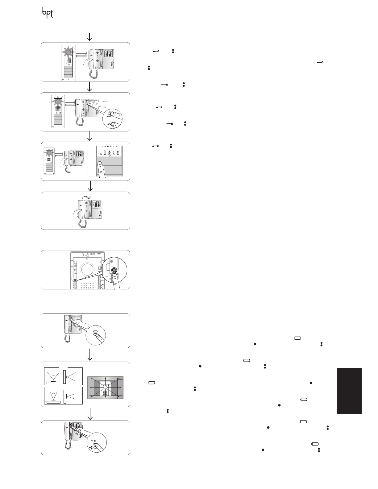
DVC/01-DVC/01 ME
OPHERA LYNEA BASICLYNEANOVAMITHOVAS/100.30
DVC/01
DVC/01 ME
e
g
f
h
Programmazione dei tasti chiamata. Sollevare la cornetta (se presente) del derivato che si desidera programmare e e premere i pulsanti
apriporta
ed AUX2 f. Premere sul posto esterno il tasto di chiamata da associare al derivato interno g: seguirà un’indicazione acustica
di avvenuta memorizzazione. Riappendere eventualmente la cornetta h e proseguire ripetendo le stesse operazioni per tutti gli altri derivati.
Programming the call keys. Lift the receiver (if present) of the extension that you want to programme e then press the door lock release and
AUX2 f buttons. On the entry panel, press the call key to associate with the internal extension g: an acoustic signal will con rm that the setting
was stored. Hang up the receiver again, if necessary h and continue, repeating the same operations for the other extensions.
Programmierung der Ruftasten. Den Hörer (falls vorhanden) der Innensprechstelle, die programmiert werden soll, e abnehmen und die
Tasten Türöff ner und AUX2 f drücken. An der Außenstation die Ruftaste drücken, die mit der Innensprechstelle g verknüpft werden
soll: es folgt ein Akustiksignal zur Bestätigung der Speicherung. Eventuell den Hörer h wieder aufl egen und die gleichen Schritte für alle anderen
Innensprechstellen wiederholen.
Programmation des touches d’appel. Soulever le combiné (si présent) du poste que l’on souhaite programmer e et appuyer sur les boutons
ouvre-porte et AUX2 f. Appuyer sur le poste extérieur sur la touche d’appel à a ssocier au poste intérieur g: suivra une indication sonore
de mémorisation e ectuée. Raccrocher éventuellement le combiné h et continuer en répétant les mêmes opérations pour tous les autres postes.
Programación de los botones de llamada. Descuelgue el auricular (en su caso) del derivado que se desea programar e y pulse los
botones abrepuerta
y AUX2 f. Pulse en la placa exterior el botón de llamada que se desea asociar al derivado interno g: seguirá una
indicación acústica para con rmar la memorización. Vuelva a colgar el auricular, en su caso, h y repita las mismas operaciones para todos los
demás derivados.
Programação das teclas de chamada. Levante o auscultador (se presente) do derivado que deseja programar e e prima os botões de abertura
da porta e AUX2 f. Prima na placa botoneira a tecla de chamada a associar ao derivado interno g: segue uma indicação acústica de
memorização efectuada. Eventualmente volte a pousar o auscultador h e continue repetindo as mesmas operações para todos os outros derivados.
Uscita dalla Programmazione. Premere brevemente il tasto PROG: i led PROG e i led dei posti esterni si spengono. NOTA. In assenza di
qualsiasi manovra, la procedura termina automaticamente dopo 30 minuti.
Exiting programming. Briefl y press the PROG key: the PROG LED and entry panel LED s will turn o . NOTE. If no action is performed, the procedure
will automatically end after 30 minutes.
Ausstieg aus der Programmierung. Die Taste PROG kurz drücken: die Leds PROG und die Leds der Außenstationen schalten sich aus. HINWEIS. Falls keine Eingabe erfolgt, endet der Vorgang automatisch nach 30 Minuten.
Sortie de la Programmation. Appuyer de façon brève sur la touche PROG: les leds PROG et les leds des postes extérieurs s’éteignent. NOTE. En cas
absence de toute manœuvre, la procédure s’arrête automatiquement après 30 minutes.
Salida de la modalidad de Programación. Pulse brevemente el botón PROG: los leds PROG y los leds de las placas exteriores se apagan.
NOTA. Si no se efectúa ninguna operación, el proceso concluye automáticamente tras 30 minutos.
Sair da Programação. Prima brevemente a tecla PROG: os leds PROG e os leds das placas botoneiras apagam-se. NOTA. Na ausência de qualquer
operação, o processo termina automaticamente após 30 minutos.
beep
i
PROG
CN1
CN4
B
B
1 2ON3
IN
OUT
PROG
DC/01DC/01 MEDVC/01DVC/01 ME
<1’’
3
8
4
6
9
7
5
2
1
76 °
55 °
37 °
50 °
1÷9
0
j
Programmazione della telecamera dei posti esterni.Durante la programmazione dei tasti chiamata è possibile regolare il “campo visivo”
della telecamera da un qualsiasi derivato (con cornetta sollevata, se presente) premendo il tasto “Autoinserimento
” j. A partire dalla
con gurazione di default è possibile scorrere le successive premendo il tasto AUX1 oppure tornare alle precedenti con il tasto AUX2 :
l’impostazione viene automaticamente salvata.
Programming the entry panel surveillance camera. When programming the call buttons, the camera’s “visual eld” can be adjusted from
any extension (with the received lifted, if present), pressing the “self-connection ” j. Starting from the default con guration, it is possible to
scroll the next ones pressing the AUX1 key or return to the previous ones with the AUX2 key : the setting will be automatically saved.
Programmierung der Telekamera der AußenstationenWährend der Programmierung der Ruftasten kann der „Sichtbereich“ der Telekamera von jeder beliebigen Innensprechstelle aus (mit abgenommenem Hörer, falls vorhanden) durch Drücken der Taste “Automatische Einschaltung” ” j eingestellt werden. Von der Standardkon guration aus können die folgenden durch Drücken der Taste AUX1 durchlaufen
werden, oder es kann mit der Taste AUX2 zu den vorhergehenden zurückgekehrt werden: die Einstellung wird automatisch gespeichert.
Programmation de la caméra des postes extérieurs. Durant la programmation des touches d’appel il est possible de régler le “champ visuel”
de la caméra depuis n’importe quel poste (avec combiné soulevé, si présent) en appuyant sur la touche “Insertion automatique ” j. À partir de
la con guration de défaut, il est possible de faire dé ler les successives en appuyant sur la touche AUX1 ou bien de retourner aux précédentes
avec la touche AUX2 : la con guration est automatiquement sauvegardée.
Programación de la cámara de las placas exteriores. Durante la programación de los botones de llamada se puede ajustar el “campo
visual” de la cámara desde cualquier derivado (con el auricular descolgado, en su caso) pulsando el botón “Autoactivación ” j. A partir de
la con guración predeterminada se pueden desplazar las siguientes pulsando el botón AUX1 o volver a las anteriores con el botón AUX2
: el ajuste se guarda automáticamente.
Programação da câmara de vídeo das placas botoneiras. Durante a programação das teclas de chamada é possível regular o “campo visual”
da câmara de vídeo a partir de qualquer um dos derivados (com auscultador levantado, se presente) premendo a tecla “Auto-inserção ” j. A
partir da con guração de default é possível consultar as seguintes premendo a tecla AUX1 ou voltar às anteriores com a tecla AUX2 : a
con guração é guardada automaticamente.
41
Page 42
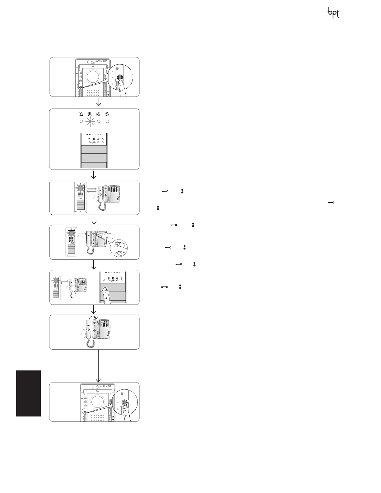
DVC/01-DVC/01 ME
OPHERALYNEA BASIC LYNEA NOVA MITHO VAS/100.30
DVC/01
DVC/01 ME
Procedura di Riprogrammazione
Reprogramming procedure
Neuprogrammierung
Procédure de Reprogrammation
Procedimiento de Reprogramación
Processo de Reprogramação
Ingresso in Programmazione. Premere per almeno 3 s il tasto PROG a e rilascire entro 6 s. L’eventuale spegnimento immediato del Led
PROG segnala un malfunzionamento. Veri care le connessioni e rientrare in programmazione. I led dei posti esterni si accenderanno come illustrato
in gura b. Attendere 5 secondi la conclusione dell’autotest e proseguire come sotto indicato.
Accessing programming. Press the PROG key a for at least 3 sec and then release it within 6 s. If the PROG LED turns o suddenly, this indicates
a malfunction. Check the connections and return to programming. The entry panel LEDs turn on as shown in the gure b. Wait 5 seconds for the
self-test to be completed and then continue as described below.
Einstieg in die Programmierung. Für mindestens 3 s die Taste PROG a drücken und innerhalb 6 s loslassen. Ein eventuelles sofortiges
Ausschalten der Led PROG zeigt. Die Anschlüsse prüfen und wieder in die Programmierung einsteigen. Die Leds der Außenstationen leuchten auf,
wie auf der Abbildung b dargestellt. 5 Sekunden bis zum Ende des Autotests warten und danach wie folgt vorgehen.
Entrée en Programmation. Appuyer pendant au moins 3 s sur la touche PROG a et relâche dans les 6 s. L’éventuelle extinction immédiate de la
Led PROG signale un dysfonctionnement. Contrôler les connexions et rentrer dans programmation. Les leds des postes extérieurs s’allumeront comme
illustré à la gure b. Attendre pendant 5 secondes la conclusion de l’autotest et continuer comme indiquÈ ci-dessous.
Entrada en la modalidad de Programación. Pulse durante al menos 3 s el botón PROG a y suéltelo antes de 6 s. Si el Led PROG se
apaga inmediatamente, signi ca que hay algún problema de funcionamiento. Compruebe las conexiones y vuelva a entrar en la modalidad de
programación. Los leds de las placas ex teriores se encenderán como se muestra en la gura b. Espere 5 segundos la conclusión de la prueba
automática y prosiga como se indica más abajo.
Entrar na Programação Prima durante pelo menos 3 seg. a tecla PROG a e solte-a dentro de 6 seg. O eventual apagamento imediato do Led
PROG sinaliza uma anomalia no funcionamento. Veri que as conexões e entre novamente na programação. Os leds das placas botoneiras acendem-se
como ilustrado na gura b. Espere 5 segundos para a conclusão do auto teste e continue como indicado a seguir.
Programmazione dei tasti chiamata. Sollevare la cornetta (se presente) del derivato che si desidera programmare c e premere i pulsanti
apriporta
ed AUX2 d. Premere sul posto esterno il tasto di chiamata da associare al derivato interno e: seguirà un’indicazione acustica
di avvenuta memorizzazione. Riappendere eventualmente la cornetta f e proseguire ripetendo le stesse operazioni per tutti gli altri derivati.
Programming the call keys. Lift the receiver (if present) of the extension that you want to programme c then press the door lock release and
AUX2 d buttons. On the entry panel, press the call key to be associated with the internal extension e: an acoustic signal will con rm that the
setting was stored. Hang up the receiver again, if necessary f and continue, repeating the same operations for the other extensions.
Programmierung der Ruftasten. Den Hörer (falls vorhanden) der Innensprechstelle, die programmiert werden soll, c abnehmen und die
Tasten Türöff ner und AUX2 d drücken. An der Außenstation die Ruftaste drücken, die mit der Innensprechstelle e verknüpft werden
soll: es folgt ein Akustiksignal zur Bestätigung der Speicherung. Eventuell den Hörer f wieder aufl egen und die gleichen Schritte für alle anderen
Innensprechstellen wiederholen.
Programmation des touches d’appel. Soulever le combiné (si présent) du poste que l’on souhaite programmer c et appuyer sur les boutons
ouvre-porte et AUX2 d. Appuyer sur le poste extérieur sur la touche d’appel à associer au poste intérieur e: suivra une indication sonore
de mémorisation e ectuée. Raccrocher éventuellement le combiné f et continuer en répétant les mêmes opérations pour tous les autres postes.
Programación de los botones de llamada. Descuelgue el auricular (en su caso) del derivado que se desea programar c y pulse los
botones abrepuerta y AUX2 d. Pulse en la placa exterior el botón de llamada que se desea asociar al derivado interno e: seguirá una
indicación acústica para con rmar la memorización. Vuelva a colgar el auricular f, en su caso, y repita las mismas operaciones para todos los
demás derivados.
Programação das teclas de chamada. Levante o auscultador (se presente) do derivado que deseja programar c e prima os botões de abertura
da porta e AUX2 d. Prima na placa botoneira a tecla de chamada a a ssociar ao derivado interno e: segue uma indicação acústica de
memorização efectuada. Eventualmente volte a pousar o auscultador f e continue repetindo as mesmas operações para todos os outros derivados.
Uscita dalla Programmazione. Premere brevemente il tasto PROG: i led PROG e i led dei posti esterni si spengono. In assenza di qualsiasi
manovra, la procedura termina automaticamente dopo 30 minuti.
Exiting programming. Briefl y press the PROG key: the PROG LED and entry panel LEDs will turn o . If no action is performed, the procedure will
end automatically after 30 minutes.
Ausstieg aus der Programmierung. Die Taste PROG drücken: die Leds PROG und die Leds der Außenstationen schalten sich aus. Falls keine
Eingabe erfolgt, endet der Vorgang automatisch nach 30 Minuten.
Sortie de la Programmation. Appuyer de façon brève sur la touche PROG : les leds PROG et les leds des postes extérieurs s’éteignent. En cas
d’absence de toute manœuvre, la procédure s’arrête automatiquement après 30 minutes.
Salida de la modalidad de Programación. Pulse brevemente el botón PROG: los leds PROG y los leds de las placas exteriores se apagan. Si
no se efectúa ninguna operación, el proceso concluye automáticamente tras 30 minutos.
Sair da Programação. Prima brevemente a tecla PR OG: os leds PROG e os leds das placas botoneiras apagam-se. Na ausência de qualquer operação, o processo termina automaticamente após 30 minutos.
a
PROG
CN1
CN4
B
B
1 2ON3
IN
OUT
PROG
DC/01DC/01 MEDVC/01DVC/01 ME
>3’’
<6’’
b
c
e
g
d
f
beep
PROG
CN1
CN4
B
B
1 2ON3
IN
OUT
PROG
DC/01DC/01 MEDVC/01DVC/01 ME
<1’’
42
Page 43
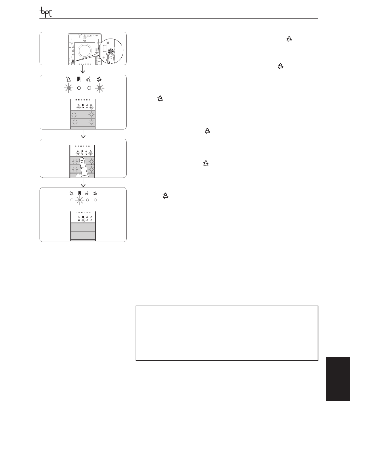
DVC/01-DVC/01 ME
OPHERA LYNEA BASICLYNEANOVAMITHOVAS/100.30
DVC/01
DVC/01 ME
Programmazione del Tipo dei Tasti. In fase di “Programmazione Tasti di Chiamata” b premere il tasto PROG h e rilascire entro 6 s. nché
si entra nella procedura “Programmazione Tipo dei Tasti” i. Premere uno dei primi 4 “tasti” del primo posto esterno il led smetterà di lampeggiare così come i led della retroilluminazione delle prime 4 posizioni dei tasti di chiamata j. Le segnalazione assumeranno la con gurazione .
Al termine, per uscire dalla programmazione, premere brevemente il tasto PROG g: i led PROG e i led dei posti esterni si spengono. In assenza di
qualsiasi manovra, la procedura termina automaticamente dopo 30 minuti.
Programming key type. During the “Call button programming” phase b press the PROG key h for at least 3 sec and then release it within 6 s.
until accessing the “Programming key type” procedure i. Press one of the rst 4 “keys” on the entry panel, the LED will stop fl ashing as will the
backlighting LED of the rst 4 call key positions j. The signals will assume the con guration .
At the end, exit programming, briefl y press the PROG key g: the PR OG LED and the entry panel LEDs will turn o . If no action is performed, the
procedure will end automatically after 30 minutes.
Programmierung der Tastenart. Während der “Programmierung der Ruf tasten” b für mindestens 3 s die Taste PROG h drücken und
innerhalb 6 s loslassen, bis man in den Vorgang “Programmierung der Tastenart” i einsteigt. Eine der ersten 4 “Tasten” der ersten Außenstation
drücken. Die Led sowie die Leds der Hintergrundbeleuchtung der ersten 4 Positionen der Ruftasten j hören zu blinken auf. Die Anzeigen
nehmen die Kon guration an.
Am Ende zum Ausstieg aus der Programmierung kurz die Taste PROG g drücken: die Leds PROG und die Leds der Außenstationen schalten sich
aus. Falls keine Eingabe erfolgt, endet der Vorgang automatisch nach 30 Minuten.
Programmation du Type des Touches. En phase de “Programmation des Touches d’Appel” b appuyer pendant au moins 3 s sur la touche
PROG h et relâche dans les 6 s jusqu’à ce que l’on entre dans la procédure “Programmation Type des touches et de l’Adresse” i. Appuyer sur une des
4 premières “touches” du premier poste extérieur, la led
arrêtera de clignoter tout comme les leds du rétroéclairage des 4 premières position des
touches d’appel j. Les signalisations adopteront la con guration .
À la n, pour sortir de la programmation, appuyer de façon brève sur la touche PROG g: les leds PROG et les leds des postes extérieurs s’éteignent. En
cas absence de toute manœuvre, la procédure s’arrête automatiquement après 30 minutes.
Programación del Tipo de los Botones. Durante la fase “Programación de los Botones de Llamada” b pulse durante al menos 3 s el botón
PROG h y suéltelo antes de 6 s hasta entrar en el proceso de “Programación del Tipo de los Botones y de la Dirección” i. Pulse uno de los 4
primeros “botones” de la primera placa exterior; el led
dejará de parpadear, así como los leds de retroiluminación de las 4 primeras posiciones
de los botones de llamada j. Las indicaciones adoptarán la con guración .
Al concluir, para salir de la modalidad de programación, pulse brevemente el botón PROG g: los leds PROG y los leds de las placas exteriores se
apagan. Si no se efectúa ninguna operación, el proceso concluye automáticamente tras 30 minutos.
Programação do Tipo de Teclas. Na fase de “Programação das teclas de Chamada” b prima durante pelo menos 3 seg. a tecla PROG h e
solte-a dentro de 6 seg. até entrar no processo de “Programação do Tipo de teclas e do Endereço” i. Prima uma das primeiras 4 “teclas” da primeira
placa botoneira, o led
deixa de piscar bem como os leds da retroiluminação das primeiras 4 posições das teclas de chamada j. As sinalizações
assumem a con guração .
No m, para sair da programação, prima brevemente a tecla PROG g: os leds PROG e os leds das placas botoneiras apagam-se. Na ausência de
qualquer operação, o processo termina automaticamente após 30 minutos.
i
j
h
PROG
CN1
CN4
1 2ON3
IN
OUT
PROG
DC/01DC/01 MEDVC/01DVC/01 ME
>3’’
<6’’
- Nel caso in cui i tasti di chiamata fossero presenti SOLO SULLE PULSANTIERE AGGIUNTIVE, procedere come indicato in NOTA a pagina 40.
- In the case that the call buttons are ONLY located on the ADDITIONAL PUSH BUTTON PANELS, proceed as indicated in NOTE on page 40.
- Falls die Ruftasten NUR AUF DEN ZUSÄTZLICHEN TASTENFELDERN vorhanden sein sollten, wie in HINWEIS auf Seite 40 gezeigt, vorgehen.
- Au cas où les touches d’appel seraient présentes UNIQUEMENT SUR LES PLATINES SUPPLÉMENTAIRES, procéder comme indiqué à la NOTE page 40.
- Si los botones de llamada estuviesen presentes SOLO EN LAS BOTONERAS ADICIONALES, siga las indicaciones de la NOTA en la página 40.
- No caso das teclas de chamada estarem presentes APENAS NAS BOTONEIRAS ADICIONAIS, proceda como indicado na NOTA página 40.
y
Programmazione della telecamera dei posti esterni. Durante la programmazione dei tasti chiamata è possibile regolare il “campo visivo”
della telecamera con le modalità già illustrate.
Programming the entry panel camera. When programming the call buttons, the camera’s “visual eld” can be adjusted as previously described.
Programmierung der Telekamera der Außenstationen. Während der Programmierung der Ruftasten kann der „Sichtbereich“ der Teleka-
mera auf die bereits beschriebene Weise eingestellt werden.
Programmation de la caméra des postes extérieurs. Durant la programmation des touches d’appel, il est possible de régler le “champ
visuel” de la caméra selon les modalités déjà illustrées.
Programación de la cámara de las placas exteriores. Durante la programación de los botones de llamada se puede ajustar el “campo
visual” de la cámara, de la manera explicada anteriormente.
Programação da câmara de vídeo das placas botoneiras Durante a programação das teclas de chamada é possível regular o “campo visual”
da câmara de vídeo das formas já ilustradas.
43
Page 44
SMALTIMENTO
Assicurarsi che il materiale d’imballaggio
non venga disperso
nell’ambiente, ma
smaltito seguendo le
norme vigenti nel paese di utilizzo del prodotto.
Alla fine del ciclo di vita
dell’apparecchio evitare che lo stesso venga
disperso nell’ambiente.
Lo smaltimento
dell ’apparec chiatura
deve essere effettuato
rispettando le norme
vigenti e privilegiando
il riciclaggio delle sue
parti costituenti.
Sui componenti, per
cui è previsto lo smaltimento con riciclaggio, sono riportati il
simbolo e la sigla del
materiale.
DISPOSAL
Do not litter the environment with packing
material: make sure it
is disposed of according to the regulations
in force in the country
where the product is
used.
When the equipment
reaches the end of its
life cycle, take measures to ensure it is not
discarded in the environment.
The equipment must
be disposed of in
compliance with the
regulations in force,
recycling its component parts wherever
possible.
Components that
qualify as recyclable
waste feature the relevant symbol and the
material’s abbreviation.
ENTSORGUNG
Vergewissern Sie sich,
dass das Verpackungsmaterial gemäß den
Vorschriften des Bes ti m mu n gs l an d es
ordnungsgemäß und
umweltgerecht entsorgt wird.
Das nicht mehr benutzbare Gerät ist umweltgerecht zu entsorgen.
Die Entsorgung hat
den geltenden Vorschriften zu entsprechen und vorzugsweise das Recycling der
Geräteteile vorzusehen. Die wiederverwertbaren Geräteteile
sind mit einem Materials.
ELIMINATION
S’assurer que le matériel d’emballage n’est
pas abandonné dans
la nature et qu’il est
éliminé conformément
aux normes en vigueur
dans le pays d’utilisation du produit.
À la fin du cycle de vie
de l’appareil, faire en
sorte qu’il ne soit pas
abandonné dans la
nature.
L’appareil doit être éliminé conformément
aux normes en vigueur
et en privilégiant le recyclage de ses pièces.
Le symbole et le sigle
du matériau sont indiqués sur les pièces
pour lesquelles le recyclage est prévu.
ELIMINACION
Comprobar que no se
tire al medioambiente
el material de embalaje, sino que sea eliminado conforme a las
normas vigentes en el
país donde se utilice el
producto.
Al final del ciclo de vida
del aparato evítese
que éste sea tirado al
medioambiente.
La eliminación del aparato debe efectuarse
conforme a las normas
vigentes y privilegiando el reciclaje de sus
partes componentes.
En los componentes,
para los cuales está
prevista la eliminación
con reciclaje, se indican el símbolo y la sigla
del material.
ELIMINAÇÃO
Assegurar-se que o
material da embalagem não seja disperso
no ambiente, mas eliminado seguindo as
normas vigentes no
país de utilização do
produto.
Ao fim do ciclo de vida
do aparelho evitar que
o mesmo seja disperso
no ambiente.
A eliminação da aparelhagem deve ser
efectuada respeitando
as normas vigentes e
privilegiando a reciclagem das suas partes
constituintes.
Sobre os componentes, para os quais é
previsto o escoamento
com reciclagem, estão
reproduzidos o símbolo e a sigla do material.
44
Page 45

45
Page 46

46
Page 47

47
Page 48
BPT S.p.A.
Via Cornia, 1
33079 Sesto al Reghena-PN-Italy
[email protected]
 Loading...