

Page 1
Manuale di Installazione
Installation Manual
Handbuch für den Installateur
Manuel d’Installation
Manual para el Instalador
Manual para o Instalador
Installatiehandleiding
OPALE WIDE
24804320/16-04-2012
1
Page 2
opale wide
Avvertenze generali
• Leggere attentamente le istruzioni, prima di iniziare l’installazione ed ese guire gli interventi come specicato dal costruttore;
• Dopo aver tolto l’imballaggio assicurarsi dell’integrità dell’apparecchio;
• Gli elementi dell’imballaggio (sacchetti in plastica, polistirolo espanso,
ecc.) non devono essere lasciati alla por tata dei bambini in quanto potenziali fonti di pericolo;
• L’installazione, la programmazione, la messa in servizio e la manutenzione
del prodotto deve essere eettuata soltanto da personale tecnico qualicato ed oppor tunamente addestrato nel rispetto delle normative vigenti
ivi comprese le osservanze sulla prevenzione infortuni;
• Operare in ambienti sucientemente illuminati e idonei per la salute e
utilizzare strumenti, utensili ed attrezzature in buono stato;
• Il dispositivo va installato conformemente al grado IP indicato nelle caratteristiche tecniche;
• L’impianto elettrico dovrà essere realizzato in conformità con le normative
in vigore nel paese di installazione;
• I conduttori dei cablaggi non utilizzati devono essere isolati.
• Saldare le giunzioni e la parte terminale dei li onde evitare malfunzionamenti causati dall’ossidazione degli stessi;
• Al termine dell’installazione, vericare sempre il corretto funzionamento
dell’apparecchiatura e dell’impianto nel suo insieme;
• Prima di eettuare qualunque operazione di pulizia o di manutenzione,
togliere l’alimentazione al dispositivo;
• In caso di guasto e/o cattivo funzionamento di un dispositivo, distaccarlo
dall’alimentazione e non manometterlo;
• Per l’eventuale riparazione rivolgersi solamente ad un centro di assistenza
tecnica autorizzato dal costruttore e comunque utilizzare sempre i ricambi
forniti da Bpt s.p.a.;
• L’apparecchio dovrà essere destinato unicamente all’uso per il quale è
stato espressamente concepito.
• Il mancato rispetto delle prescrizioni sopra elencate può compromettere la
sicurezza dell’apparecchio.
• Il costruttore non può comunque essere considerato responsabile per
eventuali danni derivanti da usi impropri, erronei ed irragionevoli.
General Precautions
• Read the instructions carefully before starting installation and proceed as
specied by the manufacturer;
• After removing the packaging, check the condition of the unit;
• The packaging items (plastic bags, expanded polystyrene, etc.) must not
be handled by children as they may be dangerous;
• Installation, programming, commissioning and maintenance of the product must only be performed by qualied technicians who have been
properly trained in compliance with current standards, including health
and safety regulations;
• Operate in suciently lighted areas that are conducive to health and use
tools, utensils and equipment that are in good working order;
• The device must be installed in accordance with the IP degree indicated in
the technical features;
• The electrical system must comply with current standards in the countr y
of installation;
• Wires belonging tocables that are not used must beinsulated.
• Weld the joints and the ends of the wires to prevent malfunctions caused
by wire oxidation;
• When installation is completed, always check for correct operation of the
unit and the system as a whole;
• Before performing any cleaning or maintenance operation, disconnect the
power supply to the device;
• In the case of device failure or malfunction, disconnect it from the power
supply and do not tamper with it;
• Should the unit be in need of repair, contact only a technical support centre authorised by the manufacturer and always use spare parts provided
by Bpt s.p.a.;
• The equipment must only be used for the purpose for which it was explicitly designed.
• Failure to follow the instructions provided above may compromise the
unit’s safety.
• The manufacturer declines all liability for any damage as a result of improper, incorrect or unreasonable use.
Allgemeine Hinweise
• Vor der Installation die Anweisungen aufmerksam lesen, und alle Arbeiten
wie vom Hersteller angegeben ausführen.
• Das Gerät aus der Verpackung nehmen und seine Unversehrtheit kontrollieren.
• Die Verpackungsteile (Plastiktüten, Polystyrolschaum usw.) dürfen nicht
in Reichweite von Kindern gelassen werden, da sie potentielle Gefahrenquellen darstellen.
• Die Installation, die Programmierung, die Inbetriebnahme und die Wartung des Produkts dürfen nur non qualiziertem und einschlägig ausgebildetem Fachpersonal unter Beachtung der geltenden Bestimmungen
und Unfallverhütungsmaßnahmen ausgeführt werden.
• In ausreichend beleuchteten und nicht gesundheitsschädigenden Räumen
arbeiten und Instrumente und Werkzeuge in gutem Zustand benutzen.
• Die Vorrichtung muss gemäß dem IP-Schutzgrad, der in den technischen
Merkmalen aufgeführt ist, installiert werden.
• Die Vorrichtungen vorsichtig handhaben: sie enthalten zerbrechliche und
feuchtigkeitsempndliche Elektronikteile.
• Um ungewollten Kontakten vorzubeugen, die Netzanschlusskabel und die
Niederspannung führenden Signalleitungen getrennt umbinden.
• Die Verbindungsstellen und das Ende der Leiter verschweißen, um Störungen durch Oxidation derselben zu vermeiden.
• Nach Abschluss der Installationsarbeiten immer den korrekten Betrieb des
Geräts und der gesamten Anlage prüfen.
• Vor allen R einigungs- oder Wartungsarbeiten die Vorrichtung von der
Spannung trennen.
• Im Fall einer Störung und/oder eines fehlerhaften Betriebs eines Geräts,
dieses sofort von der Stromversorgung trennen und keine unautorisierten
Eingrie durchführen.
• Wenden Sie sich für eventuelle Reparaturarbeiten ausschließlich an eine
vom Hersteller autorisierte Kundendienststelle und benutzen sie in jedem
Fall immer von Bpt s.p.a. geliefer te Ersatzteile.
• Das Gerät darf ausschließlich für die Zwecke benutzt werden, für die es
ausdrücklich konzipiert wurde.
• Die Nichtbeachtung der oben angeführten Vorschriften kann die Sicherheit des Geräts beeinträchtigen.
• Der Hersteller haftet nicht für Schäden, die durch einen unsachgemäßen,
falschen oder unvernünftigen Gebrauch verursacht werden.
Avertissements généraux
• Lire attentivement les instructions avant de commencer l’installation et
eectuer les opérations comme spécié par le fabricant ;
• Après l’avoir déballé, vérier que l’appareil soit en bon état ;
• Ne pas laisser les éléments d’emballage (sachets en plastique, polystyrène
expansé, etc.) à la portée des enfants car ils constituent une source potentielle de danger ;
• L’installation, la programmation, la mise en service et l’entretien du produit ne doivent être eectués que par du personnel technique qualié et
spécialisé, en respectant les normes en vigueur, y compris celles en matière de prévention des accidents ;
• Travailler dans des lieux salubres et susamment éclairés et n’utiliser que
des outils et instruments en bon état ;
• Le dispositif doit être installé conformément au degré IP indiqué dans les
caractéristiques techniques ;
• L’installation élec trique devra être réalisée en conformité aux normes en
vigueur dans le pays d’installation ;
• Les conducteurs descâblages qui ne sont pas utilisésdoivent être isolés.
• Souder les jonctions et la partie terminale des ls an d’éviter des dysfonctionnements dérivant de l’ox ydation de ceux-ci;
• À la n de l’installation, toujours contrôler le bon fonctionnement de l’appareil et de toute l’installation ;
• Avant d’eectuer toute opération de nettoyage ou d’entretien, couper
l’alimentation électrique du dispositif ;
• En cas de panne et/ou de mauvais fonc tionnement d’un dispositif, le débrancher du réseau électrique, sans tenter aucune réparation ;
• Pour toute réparation, adressez-vous uniquement à un centre d’assistance
technique agréé par le fabricant et dans tous les cas utiliser toujours des
pièces de rechange fournies par Bpt s.p.a. ;
• L’appareil n’est destiné qu’à l’utilisation pour laquelle il a été expressément conçu.
• Le non-respect des prescriptions susmentionnées pourrait compromettre
la sécurité de l’appareil.
• Le fabricant ne pourra dans tous les cas être retenu responsable des dommages dérivant d’une utilisation incorrecte ou erronée.
Advertencias generales
• Lea atentamente las instrucciones antes de comenzar la instalación, y
realice las intervenciones tal y como especica el fabricante;
• Tras haberlo sacado de su embalaje, compruebe el buen estado del aparato;
• Los elementos del embalaje (bolsas de plástico, poliestireno expandido,
etc.) no deben dejarse al alcance de los niños, ya que son potenciales
fuentes de peligro;
• La instalación, la programación, la puesta en servicio y el mantenimiento
del producto deben ser efectuados solamente por personal técnico cualicado que cuente con la formación pertinente, cumpliendo las normativas
vigentes, incluidas las normas de prevención de accidentes;
• Trabaje en entornos sucientemente iluminados e idóneos para la salud, y
utilice herramientas, utensilios y equipamiento en buen estado;
• El dispositivo debe instalarse de manera conforme al grado IP indicado en
las características técnicas;
• La instalación eléctrica deberá realizarse conforme a las normativas vigentes en el país de instalación;
• Es preciso aislar losconductores de los cableados noutilizados.
• Suelde las junturas y la parte terminal de los hilos para evitar funcionamientos defectuosos causados por su oxidación;
• Al nal del proceso de instalación, compruebe el correc to funcionamiento
del equipo y de la instalación en su conjunto;
• Antes de efectuar cualquier operación de limpieza o mantenimiento, cor te
la alimentación del dispositivo;
• En caso de avería y/o funcionamiento defectuoso de un dispositivo, desconéctelo de la alimentación y no lo manipule;
• Si es necesario efectuar reparaciones, acuda únicamente a un centro de
asistencia técnica autorizado por el fabricante, y en cualquier caso utilice
siempre los recambios suministrados por Bpt s.p.a.;
• El aparato deberá destinarse únicamente al uso para el que ha sido expresamente concebido.
• El incumplimiento de las anteriores instrucciones puede poner el peligro la
seguridad del aparato.
• En cualquier caso, el fabricante no asumirá ninguna responsabilidad por
posibles daños derivados de usos impropios, incorrectos o irrazonables.
Advertências gerais
• Leia com atenção as instruções, antes de iniciar a instalação e efectue as
operações conforme especicado pelo fabricante;
• Após ter removido a embalagem certique-se de que o aparelho está
íntegro;
• Os elementos da embalagem (sacos de plástico, isopor, etc.) não devem ser
deixados ao alcance de crianças porque são fontes potenciais de perigo;
• A instalação, a programação, a colocação em serviço e a manutenção do
produto devem ser efectuadas apenas por pessoal técnico qualicado e
com formação adequada, cumprindo as normas em vigor, inclusive as
disposições sobre a prevenção de acidentes;
• O dispositivo deve ser instalado de acordo com o grau IP indicado nas
características técnicas;
• Trate os dispositivos com cuidado: contêm componentes electrónicos frágeis e sensíveis à humidade;
• Os condutores dosconectores não utilizados devemser isolados.
• Solde as junções e a parte terminal dos os a m de evitar falsos alarmes
causados pela oxidação dos mesmos;
• No m da instalação verique sempre o funcionamento correcto do equipamento e da instalação no seu conjunto;
• Antes de efectuar qualquer operação de limpeza ou de manutenção, desligue o dispositivo da rede de alimentação eléctrica;
• No caso de avaria e/ou mau funcionamento de um dispositivo, desligue-o
da alimentação e não o abra;
• Para a eventual reparação dirija-se apenas a um centro de assistência
técnica autorizado pelo fabricante e utilize sempre as peças de reposição
fornecidas pela Bpt s.p.a.;
• O aparelho deve ser destinado unicamente ao uso para o qual foi expressamente concebido.
• O não cumprimento dos conselhos enumerados acima pode comprometer
a segurança do aparelho.
• O fabricante não pode, em todo o caso, ser considerado responsável por
eventuais danos decorrentes de usos impróprios, errados e irracionais.
Algemene waarschuwingen
• Lees aandachtig de instructies voordat u met de installatie begint en voer
de handelingen uit zoals omschreven door de fabrikant;
• Nadat u het toestel uit de verpakking heeft gehaald, controleer of het niet
beschadigd is;
• Het verpakkingsmateriaal (plastic zakjes, delen in polystyrol, enz.) dient
buiten het bereik van kinderen gehouden te worden, aangezien het gevaarlijk kan zijn;
• De installatie, het programmeren, de ingebruikname en het onderhoud
van het apparaat mag uitsluitend uitgevoerd worden door technisch bevoegd personeel dat speciek opgeleid is met betrekking tot de geldende
wetgeving, met inbegrip van het naleven van de voorschriften inzake
ongevallenpreventie;
• Handel in voldoende verlichte en gezonde ruimtes en gebruik instrumenten en gereedschap die in goede staat verkeren;
• De apparaten moeten geïnstalleerd worden conform de IP-bescherming
die vermeld is in de technische kenmerken;
• De elektrische installatie moet uitgevoerd worden volgens de wetgeving
die van kracht is in het land waar het apparaat geïnstalleerd wordt;
• Ongebruikte draden van de bekabelingen moeten geïsoleerd worden;
• Las de verbindingen en het uiteinde van de draden om te vermijden dat ze
door oxidatie aangetast kunnen worden.
• Als de installatie voltooid is, controleer altijd of de toestellen en de volledige installatie correct werken;
• Neem de voeding weg van het toestel voordat u reinigings- of onderhoudswerkzaamheden uitvoert;
• Wanneer een apparaat defect is en/of niet goed werkt, koppel het los van
de voeding en breng geen veranderingen aan;
• Wend u voor eventuele herstellingen uitsluitend tot een technisch servicecentrum dat door de fabrikant erkend is; gebruik altijd reserveonderdelen
die door Bpt s.p.a. geleverd worden;
• Het toestel is uitsluitend bestemd voor het gebruik waarvoor het uitdrukkelijk ontworpen is.
• Het niet naleven van de bovenvermelde voorschriften kan de veiligheid
van het toestel in gevaar brengen.
• De fabrikant is niet aansprakelijk voor eventuele schade die voortkomt
door oneigenlijk, foutief of onredelijk gebruik.
2
Page 3
opale wide
IT
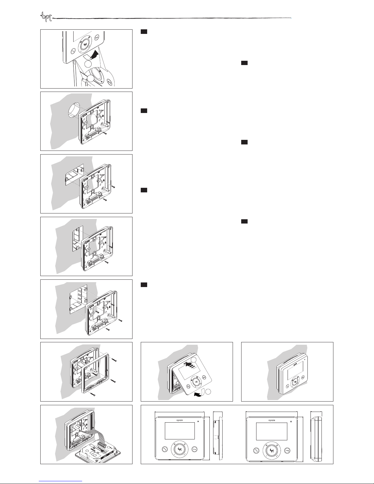
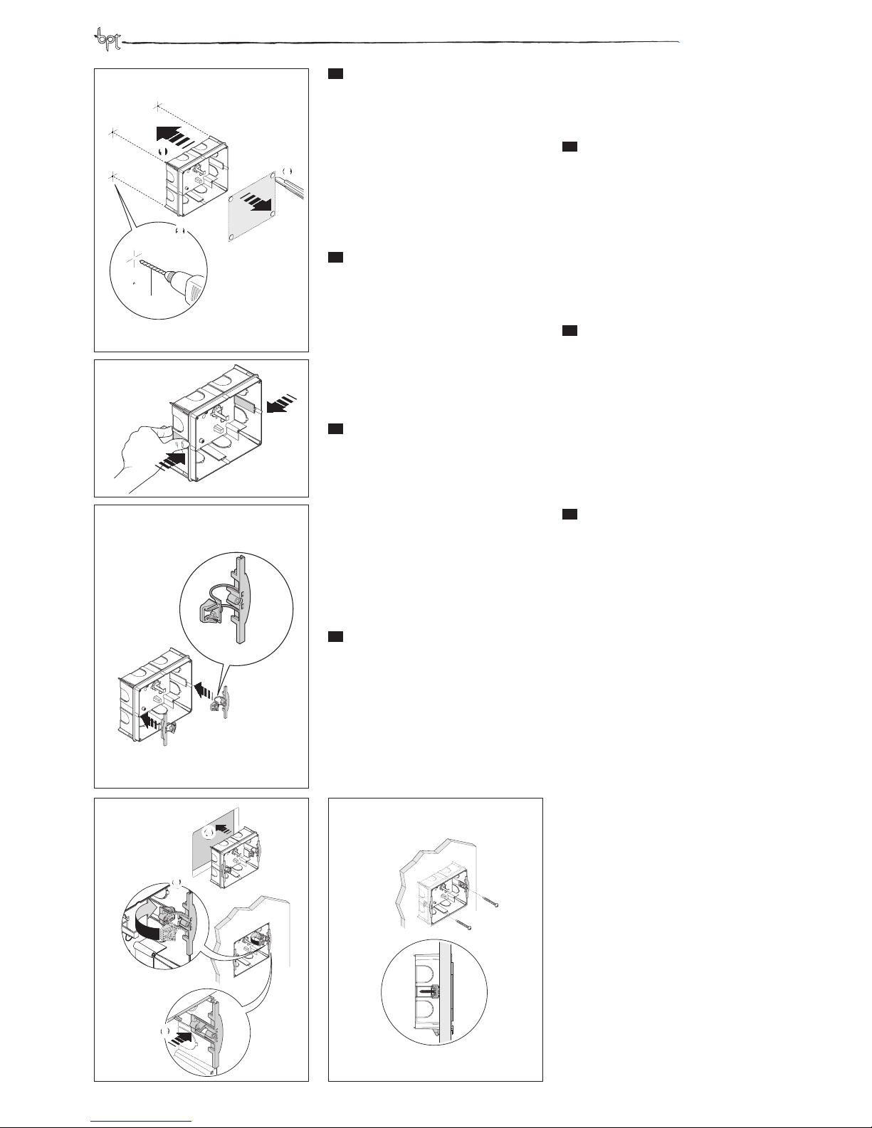
INSTALLAZIONE DA PARETE
Sganciare la cornice utilizzando un cacciavite procedendo come indicato in gura 1.
Fissare il supporto da parete alla scatola d’incasso tonda Ø 60mm (gura 2), alla scatola rettangolare 503 (gura 3 e 4) oppure alla scatola rettangolare 506E (gura 5) utilizzando le viti in dotazione. Per garantire una
maggiore stabilità al supporto si consiglia di ssarlo
anche con le viti e i tasselli forniti.
Fissare la cornice al supporto utilizzando le viti in dotazione (gura 6) ed eettuare i collegamenti (gura 7)
facendo riferimento al capitolo ‘Morsettiere’.
Agganciare il videocitofono alla cornice come indicato
in gura 8.
EN
WALL MOUNTING
Release the frame using a screwdriver as shown in
Figure 1.
Attach the wall bracket to the round recessed box Ø
60mm (Figure 2), the rectangular box 503 (Figure 3
and 4) or the rectangular box 506E (Figure 5) using
the screws provided. To ensure greater stability to the
mounting surface, secure box with screws and anchors provided.
Attach the frame to support using the supplied screws
(Figure 6) and perform connections (Figure 7) referring
to the chapter ‘ Terminal Board’.
Attach the video entry control system to the frame as
in Figure 8.
DE
WANDMONTAGE
Den Abdeckrahmen mithilfe eines Schraubenziehers
entfernen, wie in Abbildung 1 gezeigt.
Die Wandhalterung am runden Einbaugehäuse Ø
60 mm (Abbildung 2), am rechteckigen Einbaugehäuse 503 (Abbildung 3 und 4) oder am rechteckigen Einbaugehäuse 506E (Abbildung 5) mithilfe der
beiliegenden Schrauben befestigen. Für eine höhere
Stabilität an der Halterung sollte diese zusätzlich mit
den beiliegenden Schrauben und Dübel gesichert
werden.
Den Abdeckrahmen mit den beiliegenden Schrauben
an der Halterung befestigen (Abbildung 6) und die
Anschlüsse vornehmen (Abbildung 7), siehe dazu das
Kapitel ‘Klemmenbretter’.
Die Videosprechanlage wie in der Abbildung 8 gezeigt
am Abdeckrahmen befestigen.
FR
MONTAGE A MUR
Décrocher le cadre en utilisant un tournevis et en procédant comme indiqué sur la gure 1
Fixer le support à mur sur le boitier à encastrer rond Ø
60mm (gure 2), sur le boitier rectangulaire 503 (gure
3 et 4) ou sur le boitier rectangulaire 506E (gure 5) en
utilisant les vis fournies. Pour assurer une meilleure stabilité au support il est conseillé de le xer également
avec les vis et les chevilles fournies.
Fixer le cadre au support en utilisant les vis fournies
(gure 6) et procéder aux branchements (gure 7) en
se référant au chapitre “Borniers”
Fixer le portier vidéo au cadre comme illustré sur la
gure 8
ES
INSTALACIÓN MURAL
Desenganche el marco utilizando un destornillador de
la manera indicada en la gura 1.
Fije el soporte mural a la caja empotrable redonda de
Ø 60mm (gura 2), a la caja rectangular 503 (guras 3
y 4) o a la caja rectangular 506E (gura 5) utilizando los
tornillos incluidos. Para garantizar una mayor estabilidad del soporte, se recomienda jarlo también con los
tornillos y tacos incluidos.
Fije el marco al soporte utilizando los tornillos incluidos (gura 6) y realice las conexiones (gura 7) siguiendo las indicaciones del capítulo ‘Borneras’.
Enganche el videoportero al marco de la manera indicada en la gura 8.
PT
INSTALAÇÃO DE PAREDE
Desencaixe a moldura utilizando uma chave de fendas, como ilustrado na gura 1.
Fixe o suporte de parede na caixa de embutir redonda
Ø 60mm (gura 2), na caixa retangular 503 (gura 3 e
4) ou na caixa retangular 506E (gura 5), utilizando os
parafusos fornecidos. Para garantir uma maior estabilidade ao suporte, recomenda-se que também o xe
com os parafusos e as buchas fornecidos.
Fixe a moldura ao suporte utilizando os parafusos fornecidos (gura 6) e faça as ligações (gura 7) consultando o capítulo ‘Réguas de bornes’.
Encaixe o vídeo porteiro na moldura, como ilustrado
na gura 8.
NL
WANDMONTAGE
Maak het frame los met behulp van een schroevendraaier zoals weergegeven op afbeelding 1.
Maak de steun voor de wandmontage vast aan de
ronde inbouwdoos Ø 60mm (afbeelding 2), aan de
rechthoekige doos 503 (afbeelding 3 en 4) of aan de
rechthoekige doos 506E (afbeelding 5) met behulp
van de bijgeleverde schroeven. Om een grotere stabiliteit van de steun te garanderen, is het raadzaam om
hem ook vast te maken met de bijgeleverde schroeven en pluggen.
Maak het frame vast aan de steun met behulp van de
bijgeleverde schroeven (afbeelding 6) en voer de aansluitingen uit (afbeelding 7). Verwijs naar het hoofdstuk ‘Klemmenborden’.
Bevestig de deurvideo aan het frame zoals weergegeven op afbeelding 8.
4
3
2
1
7
6
10
1
2
158
138
28.5
158
30.9
138
1
2
5
8 9
506E
Clack
3
Page 4
opale wide
IT
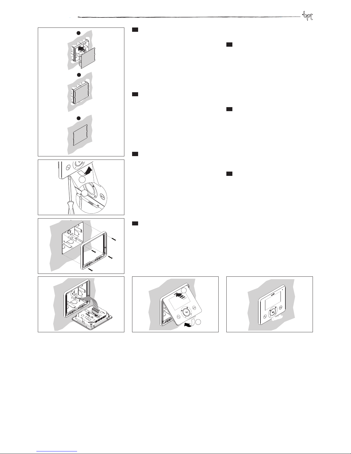
INSTALLAZIONE DA INCASSO
Installare la scatola da incasso a lo muro utilizzando
il paramalta in dotazione seguendo la procedura illustrata in gura 1.
Sganciare la cornice utilizzando un cacciavite (gura 2)
e ssarla alla scatola da incasso come indicato in gura
3 utilizzando le viti in dotazione evitando il serraggio
eccessivo delle viti.
Eettuare i collegamenti (gura 4) facendo riferimento
al capitolo ‘Morsettiere’.
Agganciare il videocitofono alla cornice come indicato
in gura 5.
EN
RECESSED WALL MOUNTING
Install the recessed box ush with wall using the mortar guard supplied by following the procedures in Figure 1.
Release the frame using a screwdriver (Figure 2) and x
it to the recessed box as in Figure 3 using the screws
provided. Do not over-tighten screws.
Perform connections (Figure 4) as shown in the chapter “Terminal Board”.
Attach the video entry control system to the frame as
in Figure 5.
DE
EINBAU
Das Einbaugehäuse mithilfe der beiliegenden Schutzabdeckung und gemäß der Vorgehensweise, die in der
Abbildung 1 dargestellt ist, wandbündig installieren.
Den Abdeckrahmen mithilfe eines Schraubenziehers
(Abbildung 2) entfernen und mit den beiliegenden
Schrauben am Einbaugehäuse befestigen, wie in der
Abbildung 3 gezeigt, ohne die Schrauben dabei zu
fest anzuziehen.
Die Anschlüsse vornehmen (Abbildung 4), siehe dazu
das Kapitel ‘Klemmenbretter’.
Die Videosprechanlage wie in der Abbildung 5 gezeigt
am Abdeckrahmen befestigen.
FR
INSTALLATION ENCASTREE
Installer le boîtier d’encastrement à eur de mur en
utilisant la plaque de protection contre le plâtre/ciment en suivant la procédure illustrée sur la gure 1
Décrocher le cadre en utilisant un tournevis (gure 2)
et le xer au boîtier d’encastrement comme indiqué
sur la gure 3 en utilisant les vis fournies sans les visser
de manière excessive.
Eectuer les branchements (gure 4) en se référant au
chapitre “Borniers”.
Accrocher le portier vidéo au cadre comme indiqué
sur la gure 5
ES
INSTALACIÓN EMPOTRADA
Instale la caja empotrable a ras de la pared utilizando la tapa de protección contra argamasa incluida y
siguiendo el procedimiento mostrado en la gura 1.
Desenganche el marco utilizando un destornillador
(gura 2) y fíjelo a la caja empotrable de la manera indicada en la gura 3 empleando los tornillos incluidos,
sin apretarlos demasiado.
Realice las conexiones (gura 4) según las indicaciones del capítulo ‘Borneras’.
Enganche el videoportero al marco de la manera indicada en la gura 5.
PT
INSTALAÇÃO DE EMBUTIR
Instale a caixa de embutir nivelada com a parede, utilizando a proteção da argamassa fornecida, seguindo o
processo ilustrado na gura 1.
Desencaixe a moldura utilizando uma chave de fendas
(gura 2) e xe-a na caixa de embutir, como ilustrado
na gura 3, utilizando os parafusos fornecidos evitando apertar excessivamente os parafusos.
Faça as ligações (gura 4) consultando o capítulo ‘Réguas de bornes’.
Encaixe o vídeo porteiro na moldura, como ilustrado
na gura 5.
NL
INBOUWMONTAGE
Installeer de inbouwdoos verzonken in de muur met
behulp van de bijgeleverde cementbescherming, zoals weergegeven op afbeelding 1.
Maak het frame los met behulp van een schroevendraaier (afbeelding 2) en maak het vast aan de
inbouwdoos zoals weergegeven op afbeelding 3
met behulp van de bijgeleverde schroeven. Draai de
schroeven niet te vast.
Voer de aansluitingen uit (afbeelding 4). Verwijs naar
het hoofdstuk ‘Klemmenborden’.
Bevestig de deurvideo aan het frame zoals weergegeven op afbeelding 5.
3
2
1
1
2
1
3
2
1
2
6
4
5
Clack
4
Page 5
opale wide
IT
INSTALLAZIONE DA INCASSO
SU PARETI IN CARTONGESSO
Premere la scatola sulla parete in cartongesso per
ricavare i 4 punti di riferimento per l’installazione ed
eettuare i fori di diametro 10 mm (g. 1).
Tagliare il cartongesso per ricavare il foro di inserimento della scatola alla parete.
Eliminare le 2 alette della scatola come indicato in gura 2.
Inserire nella scatola la parte superiore A dei morsetti
di ssaggio lasciando libera la parte inferiore B (g. 3).
Installare la scatola a parete (g. 4.4) e bloccare la parte
B del morsetto di ssaggio (g. 4.5-4.6). Fissare la scatola alla parete utilizzando le viti in dotazione (g. 5).
EN
RECESS MOUNTING ON DRYWALL
Press the box against the plasterboard panel to create
4 points of reference for installation and make holes
with a diameter of 10 mm (g. 1).
Cut the plasterboard to create the hole for insertion of
the box into the panel.
Remove the 2 tabs of the box as shown in gure 2.
Insert in the box the upper part A of the fastening
clamps, leaving the lower part free B (g. 3).
Install the box on the panel (g. 4.4) and secure part B
of the fastening terminal (g. 4.5-4.6). Fasten the box
to the panel using the screws provided (g. 5).
DE
EINBAU IN GIPSKARTONWÄNDE
Den Kasten auf der Gipskartonwand andrücken, um
die 4 Abdrücke für die Installation und die Bohrungen
mit Durchmesser 10 mm zu erhalten (Abb. 1).
Den Gipskarton für das Einsetzen des Gehäuses aufschneiden.
Wie in Abbildung 2 gezeigt, die zwei Lamellen des
Kastens entfernen.
Den oberen Teil A der Befestigungsklemmen in den
Kasten einsetzen, dabei den unteren Teil B freilassen
(Abb. 3).
Den UP-Kasten an der Wand (Abb. 4.4) installieren und
den Teil B der Befestigungsklemme (Abb. 4.5-4.6) blockieren. Mit den beiliegenden Schrauben, den Kasten
an der Wand befestigen (Abb. 5).
FR
MOTAGE ENCASTRE SUR MURS
EN PLAQUES DE PLATRE
Appuyer le boîtier sur la paroi an de repérer les 4
points de référence pour l’installation et eectuer les
trous de 10 mm de diamètre (g. 1).
Découper le placoplâtre pour obtenir l’espace nécessaire à l’installation du boîtier sur la paroi.
Éliminer les 2 ailettes du boîtier comme indiqué à la
gure 2.
Insérer la partie supérieure A des étaux de xation
dans le boîtier en laissant libre la partie inférieure B
(g. 3)
Installer le boîtier mural (g. 4.4) et bloquer la partie B
de l’étau de xation (g. 4.5-4.6). Fixer le boîtier au mur
en utilisant les vis fournies (g. 5).
ES
INSTALACIÓN EMPOTRADA EN
PAREDES DE CARTÓN-YESO
Presione la caja contra la pared de cartón-yeso para
marcar los 4 puntos de referencia para la instalación
y efectúe los oricios de 10 mm de diámetro (g. 1).
Corte el cartón-yeso para crear el hueco donde se introduce la caja en la pared.
Elimine las 2 aletas de la caja de la manera indicada
en la gura 2.
Introduzca en la caja la parte superior A de las mordazas de jación, dejando libre la parte inferior B (g. 3).
Instale la caja en la pared (g. 4.4) y bloquee la parte B
de la mordaza de jación (g. 4.5-4.6). Fije la caja a la
pared por medio de los tornillos suministrados (g. 5).
PT
INSTALAÇÃO DE EMBUTIR EM
PAREDES DE GESSO CARTONADO
Carregue a caixa na parede de gesso cartonado para
vericar os 4 pontos de referência para a instalação e
efectue os furos com diâmetro 10 mm (g. 1).
Corte o gesso cartonado para executar o furo de introdução da caixa na parede.
Elimine as 2 abas da caixa conforme indicado na gura
2.
Introduza na caixa a parte superior A dos bornes de
xação deixando livre a parte inferior B (g. 3).
Instale a caixa na parede (g. 4.4) e bloqueie a parte B
do borne de xação (g. 4.5-4.6). Fixe a caixa na parede
utilizando os parafusos fornecidos (g. 5).
NL
INBOUWMONTAGE OP
GIPSWANDEN
Houd de inbouwdoos tegen de gipswand om de 4
referentiepunten te verkrijgen. Boor gaten met een
diameter van 10 mm (afbeelding 1).
Maak een snede in de gipswand om de opening voor
de inbouwdoos te maken.
Verwijder de 2 klepjes van de doos zoals weergegeven
op afbeelding 2.
Steek de bovenkant A van de bevestigingsklemmen in
de doos. Laat de onderkant B vrij (afbeelding 3).
Plaats de doos in de wand (afbeelding 4.4) en blokkeer
deel B van de bevestigingsklem (afbeelding 4.5-4.6).
Maak de inbouwdoos vast aan de wand met behulp
van de bijgeleverde schroeven (afbeelding 5).
2
1
4
10mm
5
Ø
6
A
B
C
CLIK!
7
9
8
3
4 5
1
2
3
4
5
6
5
Page 6
opale wide
IT
INSTALLAZIONE DA INCASSO
SU PARETI IN CARTONGESSO
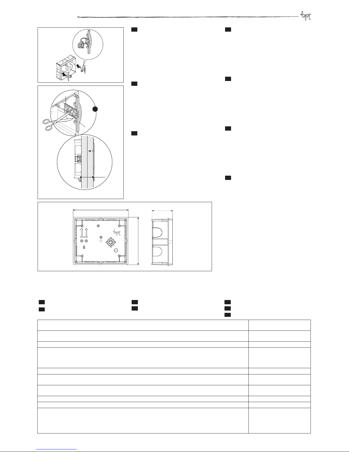
Nel caso in cui lo spessore della parete sia maggiore
di 2 cm è necessario separare le due parti dei morsetti
di ssaggio tagliando le due giunzioni (g. 6-C) come
indicato in gura 7.
Così facendo sarà possibile far scorrere la parte inferiore B del morsetto di ssaggio no alla posizione
desiderata e poi procedere con il serraggio mediante
le viti (g. 7).
EN
RECESS MOUNTING ON
DRYWALL
If the thickness of the panel is greater than 2 cm, you
will need to separate the two parts of the fastening
terminals by cutting the two joints (g. 6-C) as shown
in gure 7.
By doing so, it will be possible to slide the lower part
B of the fastening clamp to the desired position and
then proceed with tightening using the screws (g. 7).
DE
EINBAU IN GIPSKARTONWÄNDE
Falls die Wand stärker als 2 cm ist, müssen die zwei
Teile der Befestigungsklemmen mit Durchschneiden
der zwei Verbindungen (Abb. 6-C) getrennt werden,
siehe Abbildung 7.
Auf diese Weise kann man den unteren Teil B der Befestigungsklemme bis zur gewünschten Position einschieben und anschließend mit den Schrauben (Abb.
7) befestigen.
FR
MOTAGE ENCASTRE SUR MURS
EN PLAQUES DE PLATRE
Au cas où l’épaisseur de la paroi serait supérieure à 2
cm, il est nécessaire de séparer les deux parties des
étaux de xation en découpant les deux jonctions (g.
6-C) comme indiqué à la gure 7.
De cette manière, il sera possible de fait glisser la partie supérieure B de l’étau de xation jusqu’à la position
souhaitée, puis serrer à l’aide des vis (g. 7).
ES
INSTALACIÓN EMPOTRADA EN
PAREDES DE CARTÓN-YESO
Si el grosor de la pared supera los 2 cm, es necesario separar las dos partes de las mordazas de jación
cortando las dos uniones (g. 6-C) como se indica en
la gura 7.
De este modo será posible deslizar la parte inferior B
de la mordaza de jación hasta la posición deseada y
después apretar mediante los tornillos (g. 7).
PT
INSTALAÇÃO DE EMBUTIR EM
PAREDES DE GESSO CARTONADO
Se porventura a espessura da parede for maior de 2
cm é necessário separar as duas partes dos bornes de
xação cortando as duas junções (g. 6-C) como indicado na gura 7.
Dessa forma será possível fazer correr a parte inferior
B do borne de xação até à posição desejada e depois
proceder com o aperto por meio dos parafusos (g. 7).
NL
INBOUWMONTAGE OP
GIPSWANDEN
Wanneer de wand dikker is dan 2 cm, dienen de twee
delen van de bevestigingsklemmen gescheiden te
worden door de twee verbindingen door te snijden
(afbeelding 6-C), zoals weergegeven op afbeelding 7.
Zo kunt u de onderkant B van de bevestigingsklem op
de gewenste positie schuiven en vervolgens met de
schroeven vastmaken (afbeelding 7).
6
A
B
C
1
A
B
>2 cm
145
125
54
7
8
6
Alimentazione da BUS - Power supply from BUS - Stromversorgung über BUS - Alimentation depuis BUS Alimentación desde BUS - Alimentação de BUS - Voeding door BUS
15÷20 VDC
Alimentazione separata X2 - Separate power supply X2 - Getrennte Stromversorgung X2 -Alimentation séparée X2 - Alimen-Getrennte Stromversorgung X2 -Alimentation séparée X2 - Alimen- -Alimentation séparée X2 - Alimentación separada X2 - Alimentação separada X2 - Afzonderlijke voeding X2
16-18 VDC
Assorbimento - Absorption - Stromaufnahme - Absorption - Consumo - Consumo - Absorptie 330 mA max (<2,5 mA stand-by)
Assorbimento singolo LED (chiamata da portiere, esclusione suoneria) - Single LED Absorption (Porter call, ring disabled) Einzel LED Absorption (Pförtnerruf , Läutwerkabschaltung) - Absorption individuel LED (Appel concierge, Exclusion sonnerie)
- Consumo de un solo LED (Llamada conserje, Inhabilitación del timbre) - Consumo de um único LED (Chamada porteiro,
Exclusão dos sons) - Absorptie enkel lampje (oproepen van de portier, uitsluiting beltoon)
1 mA
Dimensioni - Dimensions - Maße - Dimensions - Dimensiones - Dimensões - Afmetingen 138x158x28,5 mm
Temperatura di stoccaggio - Storage temperature - Lagerungstemperatur
Température de stockage - Temperatura de almacenamiento - Temperatura de armazenagem - Bewaringstemperatuur
-25°C +70 °C
Temperatura di funzionamento - Operating temperature - Betriebstemperatur - Température de fonctionnement - Temperatura de funcionamiento - Temperatura de funcionamento - Werkingstemperatuur
0 °C +35 °C
Grado IP - IP Degree - IP-Grad - Degré IP - Grado IP - Grau IP - Beschermingsgraad IP IP 20
Standard video - Video signal system - Videostandard - Standard vidéo - Standard vídeo - Standard vídeo - Videostandaard PAL/NTSC
Display - Display - Display - Display - Display - Display - Display
LCD TFT a colori da 4,3” - 4,3” colour
LCD TFT - LCD TFT farbig zu 4,3” - LCD
TFT en couleurs de 4,3” - LCD TFT de
colores de 4,3” - LCD TFT a cores de 4,3”
- LCD TFT-kleurenmonitor van 4,3”
IT
CARATTERISTICHE TECNICHE
EN
TECHNICAL FEATURES
DE
TECHNISCHE MERKMALE
FR
CARACTÉRISTIQUES TECHNIQUES
ES
CARACTERÍSTICAS TÉCNICAS
PT
CARACTERÍSTICAS TÉCNICAS
NL
TECHNISCHE KENMERKEN
Page 7
opale wide
EN
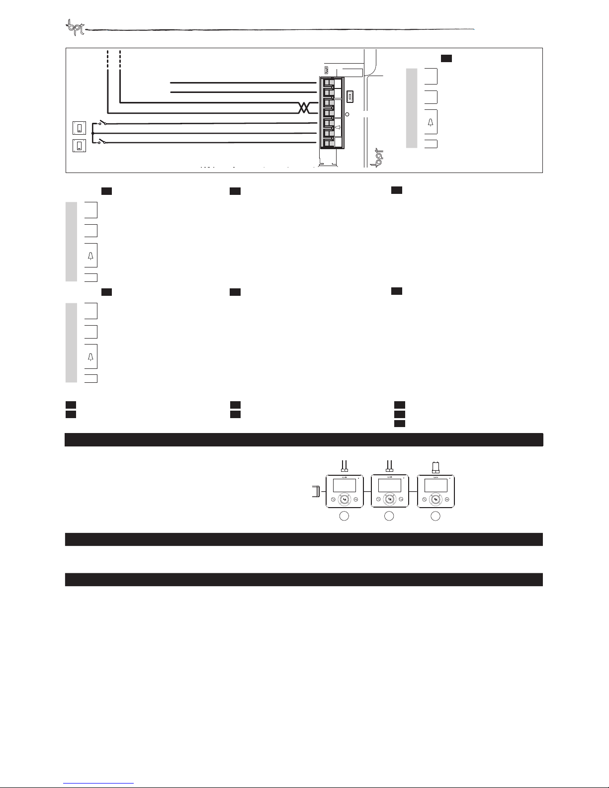
TERMINAL BOARDS
DE
KLEMMENBRETTER
FR
M1
+
Power supply local Stromversorgung örtlich Alimentation local
–
16-18 VDC 16-18 VDC 16÷18 Vcc
B
BUS line input Eingang BUS-Leitung Entrée ligne BUS
+
–
Doorbell Ruf vom Treppenhaus Appel depuis le palier
AL
Alarm input Alarmeingang Entrée alarme
ES
BORNERAS
PT
RÉGUAS DE BORNES
NL
KLEMMENBORDEN
M1
+
Alimentación local Alimentação local 16-18 Vcc
–
16÷18 Vcc 16÷18 Vcc lokale voeding
B
Entrada línea BUS Entrada linha BUS Ingang BUS-lijn
+
–
Llamada desde el rellano Chamada do patamar Deurbel
AL
Entrada alarma Entrada alarme Ingang alarm
AL
B
–
+
+
–
CL.RES
USB
M1
LED USB
16-18VDC
CL.RES
Resistenza di chiusura-Resistive load termination
Schließwiderstand-Résistance de fermeture
Resistencia de cierre-Resistência de fechoSluitingsweerstand
CL.RES
CL.RES
CL.RES
1 2
3
XDV/304
USB
Connettore per la programmazione da PC - Connector for PC setting - Verbinder für die Programmierung über PC - Connecteur de programmation par ordinateur Conector para la programación por ordenador - Conector para a programação com o PC - Aansluiting voor programmeren via PC
LED USB
Colore-Colour-Farbe-Couleur-Color-Cor-Kleur
Significato-Meaning-Bedeutung-Signification-Significado-Significado-Betekenis
Verde-Green-Grün-Vert-Verde-Verde-Groen
USB collegata-USB connected-USB angeschlossen-USB raccordée-USB conectado-USB aangesloten
IT
- SELEZIONI
EN
SELECTIONS
DE
WAHLEN
FR
SÉLECTIONS
ES
SELECCIONES
PT
SELECÇÕES
NL
SELECTIES
IT
MORSETTIERE
M1
+
16-18 Vcc
–
alimentazione locale
B
Ingresso linea BUS
+
–
Chiamata pianerottolo
AL
Ingresso allarme
7
Page 8
opale wide
IT
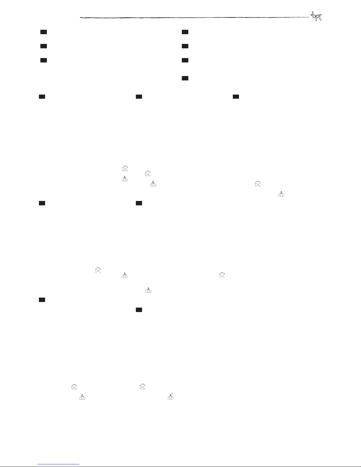
Derivato alimentato da bus (X1)
- Terminale inattivo: schermo spento;
- Suonerie chiamata da pianerottolo e allarme: non
polifoniche e non con gurabili;
- Presenza nuovo messaggio da por tiere o in segrete-
ria: icona AUX2 •• accesa;
- Regolazione retroilluminazione in modalità stand-
by e del tempo di innatività: assenti.
Derivato alimentato da LOCALE (X2)
- Terminale inattivo: schermo in stand-by (luminosità
attenuata);
- Suonerie chiamata da pianerottolo e allarme: polifoniche con gurabili;
- Presenza nuovo messaggio da por tiere: icona
lampeggiante;
- Presenza nuovo messaggio in segreteria: icona
lampeggiante.
- Regolazione retroilluminazione in modalità standby e del tempo di innatività: presenti.
EN
Bus powered receiver (X1)
- Terminal idle: screen o ;
- Rings Input call or alarm: not polyphoonic or con -
gurable;
- New message from porter or on answer phone: icon
AUX2 •• on;
- Adjustable backlighting in stand-by mode and idle
time: none.
Receiver powered LOCALLY (X2)
- Terminal idle: screen in stand-by (low lighting);
- Ring Input call and alarm: con gurable polyphoo-
nic;
- New message from por ter: icon
ashes;
- New message on answering phone: icon
ashes.
- Adjustable backlighting in stand-by mode and idle
time: available.
DE
Sprechstelle mit Stromversorgung über
BUS (X1)
- Terminal nicht aktiv: Bildschirm aus;
- Läutwerk für Anrufe vom Treppenhaus und Alarm:
nicht polyphonisch und nicht kon gurierbar;
- Vorhandensein neuer Nachrichten von der Pförtnerzentrale oder auf dem Anrufbeantwor ter: Symbol
AUX2•• ist an;
- Einstellung der Hintergrundbeleuchtung in Standby und der Zeit der Inaktivität: nicht vorhanden.
Mit Stromversorgung von LOKAL (X2)
- Terminal nicht aktiv: Bildschirm in Stand-by (geringere Helligkeit);
- Läutwerk für Anrufe vom Treppenhaus und Alarm:
polyphonisch und kon gurierbar;
- Vorhandensein neuer Nachrichten von der Pförtnerzentrale: Symbol
blinkt;
- Vorhandensein neuer Nachrichten auf dem Anrufbeantworter: Symbol
blinkt.
- Einstellung der Hintergrundbeleuchtung in Standby und der Zeit der Inaktivität: vorhanden.
FR
Poste alimenté par le bus (X1)
- Terminal inactif: écran éteint;
- Sonnerie d’appel au palier et d’alarme: non poly-
phoniques et non con gurables;
- Présence d’un nouveau message du concierge ou
sur le répondeur: icône AUX2 •• visible;
- Réglage du rétroéclairage en modalité stand-by et
de la durée d’inactivité: absents.
Poste alimenté par en mode LOCAL (X2)
- Terminal inactif: écran en stand-by (luminosité atténuée);
- Sonnerie d’appel au palier et d’alarme: polyphoniques con gurables;
- Présence d’un nouveau message du concierge: icone
clignotante;
- Présence d’un nouveau message sur le répondeur:
icône
clignotante.
- Réglage du rétroéclairage en modalité stand-by et
de la durée d’inactivité: présents.
ES
Derivado alimentado desde bus (X1)
- Terminal inactivo: pantalla apagada;
- Timbres de llamada desde rellano y alarma: no poli-
fónicos y no con gurables;
- Presencia de nuevo mensaje del conserje o en el contestador: icono AUX2 •• encendido;
- Regulación de la retroiluminación en modalidad de
stand-by y del tiempo de inactividad: ausentes.
Derivado alimentado desde LOCAL (X2)
- Terminal inactivo: pantalla en stand-by (brillo atenuado);
- Timbres de llamada desde rellano y alarma: polifónicos con gurables;
- Presencia de nuevo mensaje del conserje: icono
parpadeando;
- Presencia de nuevo mensaje en el contestador: icono
parpadeando.
- Regulación de la retroiluminación en modalidad de
stand-by y del tiempo de inactividad: presentes.
PT
Derivado alimentado por bus (X1)
- Terminal inativo: ecrã apagado;
- Tons de chamada do patamar e alarme: não polifó-
nicos e não con guráveis;
- Presença de mensagem nova do porteiro ou no
atendedor de chamadas: símbolo AUX2 •• aceso;
- Regulação da luz de fundo no modo de stand-by e
do tempo de inatividade: ausentes.
Derivado alimentado por LOCAL (X2)
- Terminal inativo: ecrã em stand-by (brilho atenuado);
- Tons de chamada do patamar e alarme: polifónicos
e con guráveis;
- Presença de mensagem nova do porteiro: símbolo
intermitente;
- Presença de mensagem nova no atendedor de chamadas: símbolo
intermitente.
- Regulação da luz de fundo no modo de stand-by e
do tempo de inatividade: presentes.
NL
Derivado alimentado por bus (X1)
Post gevoed door bus (X1)
- Terminal niet ingeschakeld: scherm uit;
- Beltonen deurbel en alarm: niet polyfonisch en niet
con gureerbaar;
- Aanwezigheid van nieuwe berichten van de portier
of op het antwoordapparaat: pictogram AUX2 ••
aan;
- Regelen achtergrondverlichting in stand-bymodus
en inactiviteitstijd: afwezig.
Plaatselijk gevoede post (X2)
- Terminal niet ingeschakeld: scherm in stand-by
(verminderde helderheid);
- Beltonen deurbel en alarm: polyfonisch en con gureerbaar;
- Aanwezigheid van nieuwe berichten van de portier:
pictogram
knippert;
- Aanwezigheid van nieuwe berichten op het antwoordapparaat: pictogram
knippert.
- Regelen achtergrondverlichting in stand-bymodus
en inactiviteitstijd: aanwezig.
IT
DIFFERENZE DI FUNZIONAMENTO TRA DERIVATO
ALIMENTATO DA BUS O LOCALMENTE
FR
DIFFÉRENCES DE FONCTIONNEMENT ENTRE POSTE
ALIMENTÉ PAR LE BUS OU LOCALEMENT
EN
FUNCTIONAL DIFFERENCE BETWEEN RECEIVER
POWERED THROUGH BUS OR LOCALLY
ES
DIFERENCIAS DE FUNCIONAMIENTO ENTRE DERIVADO ALIMENTADO DESDE BUS O DESDE LOCAL
DE
FUNKTIONSUNTERSCHIEDE ZWISCHEN DER
SPRECHSTELLE MIT STROMVERSORGUNG ÜBER BUS
ODER LOKAL
PT
DIFERENÇAS DE FUNCIONAMENTO ENTRE DERIVADO
ALIMENTADO POR BUS OU LOCALMENTE
NL
VERSCHILLEN IN DE WERKING TUSSEN DOOR EEN
BUS OF PLAATSELIJK GEVOEDE POSTEN
8
Page 9
opale wide
IT
PROGRAMMAZIONE DEI TASTI DI CHIAMATA
FR
PROGRAMMATION DES TOUCHES D’APPEL
EN
CALL BUTTON SETTING
ES
PROGRAMACIÓN DE LOS BOTONES DE LLAMADA
DE
PROGRAMMIERUNG DER RUFTASTEN
PT
PROGRAMAÇÃO DAS TECLAS DE CHAMADA
NL
HET PROGRAMMEREN VAN DE OPROEPTOETSEN
9
IT
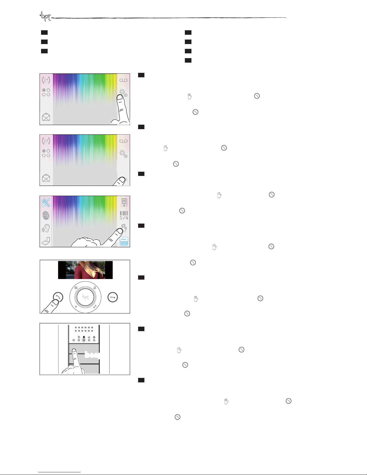
- Ingresso in Programmazione. Entrare in Programmazione dell’impianto seguendo le modalità riportate
nel manuale di Programmazione del posto esterno.
Programmazione Tasti di chiamata. Accedere alla pagina SETUP Tecnico del derivato interno OPALE WIDE ( gura e ) e premere l’icona
seguita dal pulsante di chiamata
Premere sul posto esterno il tasto di chiamata ( gura ) da associare al derivato interno: seguirà un’indicazione
acustica di avvenuta memorizzazione.
Premere il pulsante di chiamata
per terminare la programmazione e ripetere la medesima procedura per gli
altri derivati OPALE WIDE.
EN
- Entering Programming Mode. Enter the setting mode of the system by following the instructions in the
Entry Panel Settings manual.
Call button setting. Access the Service SETUP page of the OPALE WIDE internal extension (Figures and ) and
press the icon followed by the call button
.
Press the call button on the external panel ( gure ) to connect to the internal extension: a sound signal indicates
settings saved.
Press the call button
to end setting phase and repeat the same steps for the other OPALE WIDE extensions.
DE
- Zugang zur Programmierung. Rufen Sie den Programmiermodus der Anlage auf, indem Sie den Modalitä-
ten befolgen, die in der Anleitung für die Programmierung der Außenstation angegeben sind.
Programmierung der Ruftasten. Rufen Sie die Seite Dienst SETUP der Innensprechstelle OPALE WIDE auf (Abbildung und ) und drücken Sie das Symbol
gefolgt von der Ruftaste
.
Drücken Sie an der Außenstation die Ruftaste (Abbildung ), die der Innensprechstelle zugewiesen werden soll:
ein akustisches Signal weist daraufhin, dass der Vorgang abgespeichert wurde.
Drücken Sie die Ruftaste
, um die Programmierung zu beenden und wiederholen Sie den gleichen Vorgang für
die andern Sprechstellen OPALE WIDE.
FR
- Passage en mode programmation Passer en mode programmation de l’installation en suivant les moda-
lités reportées dans le manuel de programmation du poste extérieur.
Programmation des touches d’appel Accéder à la page de la CONFIGURATION Service du poste interne OPALE
WIDE ( gure e ) et appuyer sur l’icône
puis sur le bouton d’appel
.
Appuyer sur le bouton d’appel du poste extérieur ( gure ) à associer au poste interne: un signal acoustique
indiquera que la programmation a été e ectuée
Appuyer sur le bouton d’appel
pour terminer la programmation e répéter la même procédure pour les autres
postes OPALE WIDE.
ES
- Entrada en la modalidad de Programación Entre en la modalidad de Programación de la instalación
siguiendo los procedimientos indicados en el manual de Programación de la placa externa.
Programación de los botones de llamada. Acceda a la página SETUP Servicio del derivado interno OPALE WIDE
( guras y ) y pulse el icono
seguido del botón de llamada
Pulse en la placa externa el botón de llamada ( gura ) que desea asociar al derivado interno: se emitirá una señal
acústica para con rmar la memorización.
Pulse el botón de llamada para nalizar la programación y repita el mismo procedimiento para los demás
derivados OPALE WIDE.
PT
- Entrar em Programação. Entre na Programação do sistema seguindo as instruções presentes no manual
de Programação da placa botoneira.
Programar as Teclas de chamada. Aceda à página SETUP Serviço do derivado interno OPALE WIDE ( gura e
) e prima o símbolo
seguido da tecla de chamada
.
Prima na placa botoneira a tecla de chamada ( gura ) a associar ao derivado interno: segue-se um sinal sonoro
de memorização bem sucedida.
Prima a tecla de chamada
para terminar a programação e repita o mesmo processo para os outros derivados
OPALE WIDE.
NL
- Toegang tot de programmeerfunctie. Open Programmeren van de installatie zoals vermeld in de han-
dleiding Programmeren van de buitenpost.
Het programmeren van de oproeptoetsen. Ga naar de Technische SETUP-pagina van de OPALE WIDE-binnenpost (afbeelding en ), druk op het pictogram
en vervolgens op de belknop
Druk op de beltoets van de buitenpost (afbeelding ) die u aan de binnenpost wilt koppelen. Vervolgens geeft
een geluidssignaal weer dat de con guratie opgeslagen is.
Druk op de belknop
om het programmeren te voltooien. Herhaal deze procedure voor alle andere OPAL
WIDE-posten.
Tuesday 13 September 2012
12:45
beep
Tuesday 13 September 2012
12:45
Page 10
opale wide
10
IT
- DISTANZE
EN
DISTANCES
DE
ABSTÄNDE
FR
DISTANCE
ES
DISTANCIAS
PT
DISTÂNCIAS
NL
AFSTANDEN
VA/01
VAS/101
VAS/101
MAX
VAS/101 VAS/101
Lc
La
Lb
L1 L2 L3
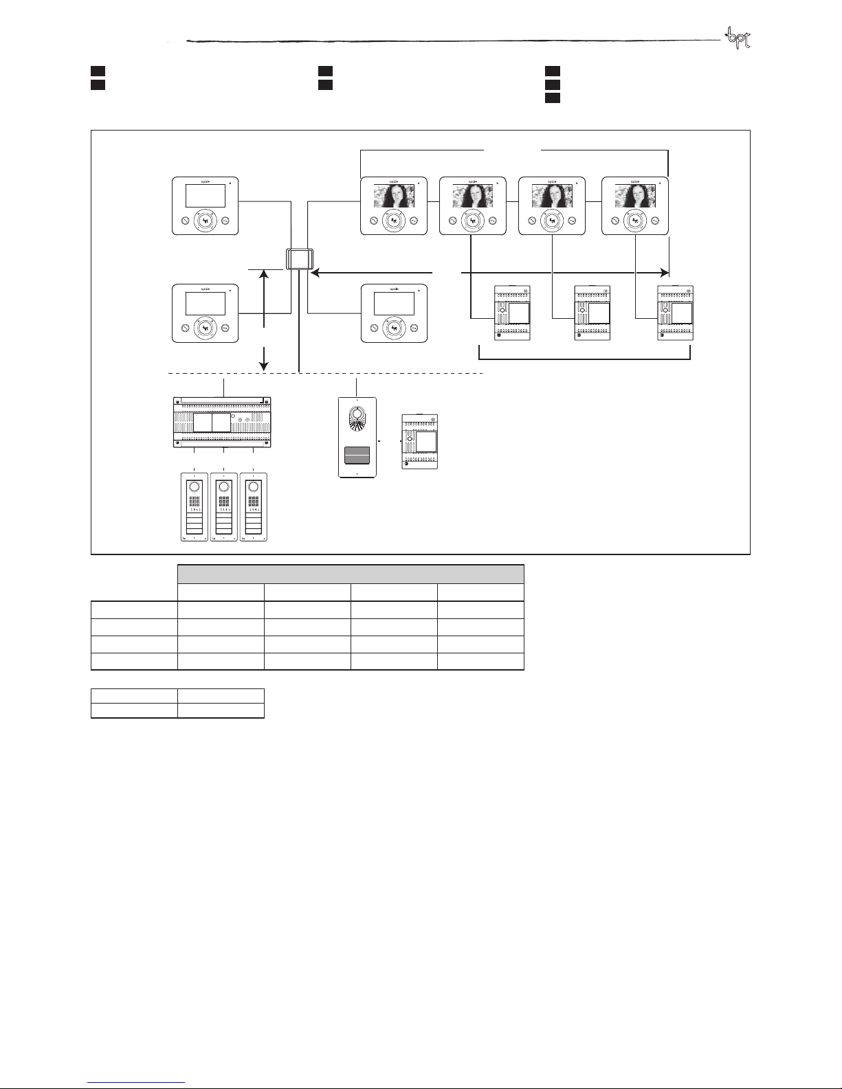
Distanze-Distances-Abstände-Distances-Distancias-Distâncias-Afstanden
VCM/1D VCM/2D UTP/CAT 5 2x2,5mm
2
La+Lb ≤100 m – ≤50 m –
Lc ≤25 m – – ≤60 m
L1, L2, L3 – ≤100 m – –
L1+L2+ L3 – ≤300 m – –
La+Lb+L1(L2, L3) ≤150 m
La+Lb+L1+L2+L3 ≤600 m
Alimentazione locale - Power supply local
Stromversorgung örtlich - Alimentation local
Alimentación local - Alimentação local -
Lokale voeding
Page 11
opale wide
11
Page 12
BPT S.p.A.
Via Cornia, 1
33079 Sesto al Reghena-PN-Italy
[email protected]
SMALTIMENTO
Assicurarsi che il materiale d’imballaggio
non venga disperso
nell’ambiente, ma
smaltito seguendo
le norme vigenti nel
paese di utilizzo del
prodotto.
Alla ne del ciclo di
vita dell’apparecchio evitare che lo
stesso venga disperso nell’ambiente.
Lo smaltimento
dell’apparecchiatura
deve essere eettuato rispettando
le norme vigenti e
privilegiando il riciclaggio delle sue
parti costituenti.
Sui componenti,
per cui è previsto
lo smaltimento con
riciclaggio, sono riportati il simbolo e
la sigla del materiale.
DISPOSAL
Do not litter the
environment with
packing material:
make sure it is disposed of according
to the regulations in
force in the country
where the product
is used.
When the equipment reaches the
end of its life cycle,
take measures to
ensure it is not discarded in the environment.
The equipment
must be disposed of
in compliance with
the regulations in
force, recycling its
component parts
wherever possible.
Components that
qualify as recyclable
waste feature the
relevant symbol and
the material’s abbreviation.
ENTSORGUNG
Vergewissern Sie
sich, dass das Verpa cku ngs mater ial
gemäß den Vorschriften des Best imm ung sla nde s
ordnun gsgemä ß
und umweltgerecht
entsorgt wird.
Das nicht mehr benutzbare Gerät ist
umweltgerecht zu
entsorgen.
Die Entsorgung hat
den geltenden Vorschriften zu entsprechen und vorzugsweise das Recycling
der Geräteteile vorzusehen. Die wieder ve rw er tb ar en
Geräteteile sind mit
einem Materials.
ELIMINATION
S’assurer que le matériel d’emballage
n’est pas abandonné
dans la nature et
qu’il est éliminé
conformément aux
normes en vigueur
dans le pays d’utilisation du produit.
À la n du cycle de
vie de l’appareil,
faire en sorte qu’il ne
soit pas abandonné
dans la nature.
L’appareil doit être
éliminé conformément aux normes en
vigueur et en privilégiant le recyclage de
ses pièces.
Le symbole et le
sigle du matériau
sont indiqués sur
les pièces pour lesquelles le recyclage
est prévu.
ELIMINACION
Comprobar que no
se tire al medioambiente el material de
embalaje, sino que
sea eliminado conforme a las normas
vigentes en el país
donde se utilice el
producto.
Al nal del ciclo de
vida del aparato
evítese que éste sea
tirado al medioambiente.
La eliminación del
aparato debe efectuarse conforme a
las normas vigentes
y privilegiando el reciclaje de sus partes
componentes.
En los componentes, para los cuales
está prevista la eliminación con reciclaje, se indican el
símbolo y la sigla del
material.
ELIMINAÇÃO
Assegurar-se que o
material da embalagem não seja disperso no ambiente,
mas eliminado seguindo as normas
vigentes no país de
utilização do produto.
Ao m do ciclo de
vida do aparelho
evitar que o mesmo
seja disperso no ambiente.
A eliminação da
aparelhagem deve
ser efectuada respeitando as normas
vigentes e privilegiando a reciclagem
das suas partes
constituintes.
Sobre os componentes, para os
quais é previsto o
escoamento com
reciclagem, estão
reproduzidos o símbolo e a sigla do
material.
AFDANKING
Zorg ervoor dat het
materiaal van de
verpakking niet in
het milieu terechtkomt, maar afgedankt wordt volgens
de wetgeving die
van kracht is in het
land waar het product gebruikt wordt.
Vermijd dat het toestel aan het einde
van haar levensduur
in het milieu terechtkomt.
Het toestel moet afgedankt worden in
overstemming met
de geldende wetgeving. Geef voorkeur
aan het recyclen van
de onderdelen.
Op de onderdelen
die gerecycled kunnen worden is het
symbool en de afkorting van het materiaal aangebracht.
 Loading...