

Page 1

KNX 8-channel 16A actuator - DIN rail mounting
KNX 12-channel 16A actuator - DIN rail mounting
Technical Manual
KX8O16A KX12O16A
24809180/24-02-2014
Page 2

Page 3
3
- General information
Dynamic administration of group addresses
Maximum no. of group addresses and associations: 152
Device selection:
The application must rst be adapted to the hardware in use. When changing over the device selection, parameter settings and linked group addresses
are modied by the ETS program. For this reason, the
device selection should be set before conguring
the device.
Parameters
Device selection
Parameter Setting
Device selection 8-gang switch actuator
12-gang switch actuator
Function
When the application is loaded, the following functions can
be implemented and controlled via the bus:
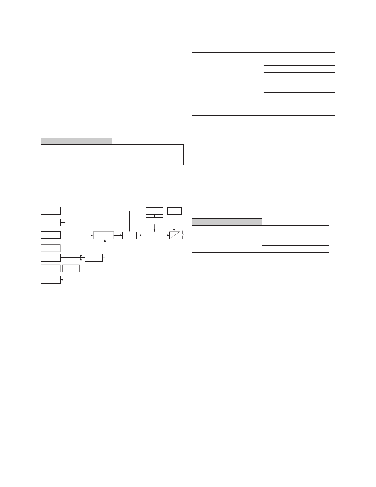
Block diagram:
With regard to the switching behaviour of the actuator,
each function has a certain priority. The weighting of the
functions can be taken from the following table:
Priority
function
Logic
object
Priority
object
Disable
object
Status feed
back object
Switch and
time logic
Bus voltage
failure
Relay
Relay operating
function
Central
switching object
Disable
function
Scene
object
Bus voltage
recovery
ETS
download
Scene
memory
Switch
object
Priorities:
Priority Function
Highest priority Relay state after bus voltage failure
Disable function
Priority function
Logic operation
Priority control
Relay state after bus voltage recovery/ETS download
Lowest priority Switching, time, central and scene
functions
Behaviour on bus voltage failure/reset
- Behaviour on bus voltage failure
When the bus voltage drops below 18 V, the relay can
adopt a parameterised state. The relay can either be closed,
opened or remain in the position it occupied prior to the
failure. At the same time, the current switching position of
the relay is stored in the device. Only the actual relay state
(“1” for closed; “0” for opened) at the time of the voltage
failure is saved and not any active time delays. No further
status response telegrams are sent. This function has the
highest priority.
Parameters
Channel X: General
Parameter Setting
Relay state after bus voltage
failure
no change
opened
closed
- Behaviour on bus voltage recovery
On bus voltage recovery, the relay can adopt a parameterised state. The following options are available for selection.
In the settings “opened” or “closed”, the relay contact is
opened or closed. An inversion does not take place in the
“break contact” relay mode.
Staircase lighting functions: In the “make contact” mode,
the staircase lighting function starts with the setting
“closed”. This also happens in the “break contact” mode with
the setting “opened ”.
In the setting “no change”, the relay remains in the current
state. Any manual operation that occurs in the meantime
(with 2-gang and 4-gang switch actuators) is retained. The
device does not know the status of the channel at this point
and therefore no status signal can take place. The status is
only available following a switching action of the channel.
In the setting “as for bus voltage failure”, the relay adopts
the state which was stored in the device on bus voltage
failure. Any manual operations that occur (with 2-gang
and 4-gang switch actuators) are overwritten. There are no
stored states once the application has been downloaded.
This means that the output is opened in the “make contact”
mode while the relay closes in the “break contact” mode.
If the setting “ash” is selected, the relay starts to ash on
bus voltage recovery. The ashing interval can be set.
Page 4
4
for the reconguration of switch actuators in occupied
buildings so that the outputs do not switch in the event of
a download. The device does not know the status of the
channel at this point and therefore no status signal can
take place. The status is only available following a switching
action of the channel.
If the option “as for bus voltage recovery” is selected, the
setting for the parameter “Relay state after bus voltage
recovery” is adopted.
See: Behaviour on bus voltage recovery
Before triggering the relay, a check is made to determine
whether there is sucient energy to operate the relay. If
there is sucient energy, the relay immediately switches
to the parameterised state. Otherwise there is a delay until
sucient energy is available.
Important:
Relay states that are caused by functions with a
higher priority (higher priority function) take precedence over the behaviour after ETS download.
Example: OR logic operation with parameterised
value of the logic object after bus voltage recovery =
1 takes priority and switches the output.
Status response
Each channel can deliver a status response, depending on
the parameter settings. An exception is made in the setting
“no change”: since the current status cannot be reliably
determined, no status telegram is sent.
Parameters
Channel X: General
Parameter Setting
Relay state after ETS download no change
opened
closed
as for bus voltage recovery
Important
No short switching times may be parameterised
under load (see the technical data for the switch
output)
Before triggering the relay, a check is made to determine
whether there is sucient energy to operate the relay. If
there is sucient energy, the relay immediately switches
to the parameterised state. Otherwise there is a delay until
sucient energy is available.
Important:
Relay states that are caused by functions with a higher priority (higher priority function) take precedence
over the behaviour after bus voltage recovery.
Example: OR logic operation with parameterised
value of the logic object after bus voltage recovery =
1 takes priority and switches the output.
Status response
Each channel can deliver a status response, depending on
the parameter settings. An exception is made in the setting
“no change”: since the current status cannot be reliably
determined, no status telegram is sent.
Parameters
Channel X: General
Parameter Setting
Relay state after bus voltage
recovery
no change
as for bus voltage failure
opened
closed
ash
If “ash” is selected, the ashing interval must be set.
Flashing interval
Parameter Setting
Flashing interval base 100 ms
1 s
1 min
1 hr
Flashing interval factor [5-255] 10
adjustable in single steps
- Behaviour after ETS download
After the ETS download, the relay can adopt a parameterised state. The following options are available for selection.
In the settings “opened” or “closed”, the relay contact is
opened or closed. An inversion does not take place in the
“break contact” relay mode.
Staircase lighting functions: In the “make contact” mode,
the staircase lighting function starts with the setting
“closed”. This also happens in the “break contact” mode with
the setting “opened ”.
In the setting “no change”, the relay remains in the state it
occupied prior to the download. Any manual operation that
occurs in the meantime (with 2-gang and 4-gang switch
actuators) is not overwritten. This function is conceived
Page 5
5
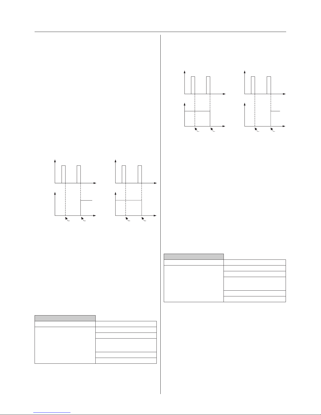
- Relay operation: break contact
The relay contact can be operated logically as a break contact (via software). The relay position is inverted and issued.
Switch (break function)
The xed relay positions (open, closed) within the other
functions are triggered directly. An inversion by means of
the break contact function is no longer carried out for these
xed relay positions.
Status response
Each channel can deliver a status response, depending on
the parameter settings. This always conveys the actual state
of the output (1= relay closed; 0= relay opened).
After bus voltage recovery, the relay is normally closed
in the “break contact” function and if the status feedback
function is active, a status response telegram is generated
with the value “1” after approx. 17 s. In this case, a function
with a higher priority enforces a dierent state and the
corresponding status response telegram is produced.
Parameters
Per channel: Select the “break contact” relay mode
Channel X: General
Parameter Setting
Relay operation make contact
break contact
changeover contact (channel 1:
make contact / channel 2: break
contact)
ash for ON
ash for OFF
- Relay operation: changeover contact
The changeover function is only available for the odd-numbered channels i.e.1, 3, 5, 7, etc. The even-numbered channels are integrated in the changeover function as a second
contact.
In this operation mode, the two adjacent channels e.g. “1”
and “2” are combined logically as a changeover contact. The
two relays then work inversely to each other. The switching
state is determined by the odd-numbered channel “1”.
open
t
t
10
remains
closed
is
opened
EIB
telegram
Relay status
closed
Relay status
closed
t
remains
open
is
closed
open
t
1 0
EIB
telegram
Switching on Switching off
Relay operation
The operation mode of the relay can be set via the parameter “Relay operation”. The relay can be used as a “break contact”, “make contact”, “changeover contact” or as a ashing
indicator. The changeover function is only available for the
odd-numbered channels i.e.1, 3, etc. The even-numbered
channels are integrated in the changeover function as a
second contact.
When changing over the relay operation mode,
parameter settings and linked group addresses are
modied by the ETS program. For this reason, the
relay operation mode should be set before conguring the device.
- Relay operation: make contact
The relay in the switch actuator has a make contact. The
switching state is transmitted directly to the relays.
Switch (make function)
Status response
Each channel can deliver a status response, depending on
the parameter settings. This always conveys the actual state
of the output (1= relay closed; 0= relay opened).
After bus voltage recovery, the relay is normally opened in
the “make contact” function. When the contact is opened
and the status feedback function is active, no “0” telegrams
are generated. In this case, a function with a higher priority
enforces a dierent state and the corresponding status
response telegram is produced.
Parameters
Per channel: Select the “make contact” relay mode
Channel X: General
Parameter Setting
Relay operation make contact
break contact
changeover contact (channel 1:
make contact / channel 2: break
contact)
ash for ON
ash for OFF
open
t
t
10
remains
open
is
closed
KNX
telegram
Relay status
closed
Relay status
closed
t
remains
closedisopened
open
t
1 0
KNX
telegram
Switching on Switching off
Page 6
6
Flash for ON
Status response
Each channel can deliver a status response, depending on
the parameter settings. This always conveys the actual state
of the output (1= relay closed; 0= relay opened).
Parameters
Per channel: Select the relay mode “ash for ON” or
“ash for OFF”
Channel X: General
Parameter Setting
Relay operation make contact
break contact
changeover contact (channel 1:
make contact / channel 2: break
contact)
ash for ON
ash for OFF
Set the ashing interval for the device.
Flashing interval
Parameter Setting
Flashing interval base 100 ms
1 s
1 min
1 hr
Flashing interval factor [5-255] 10
adjustable in single steps
open
1
0
closed
Relay
Status
actuated
not actuated
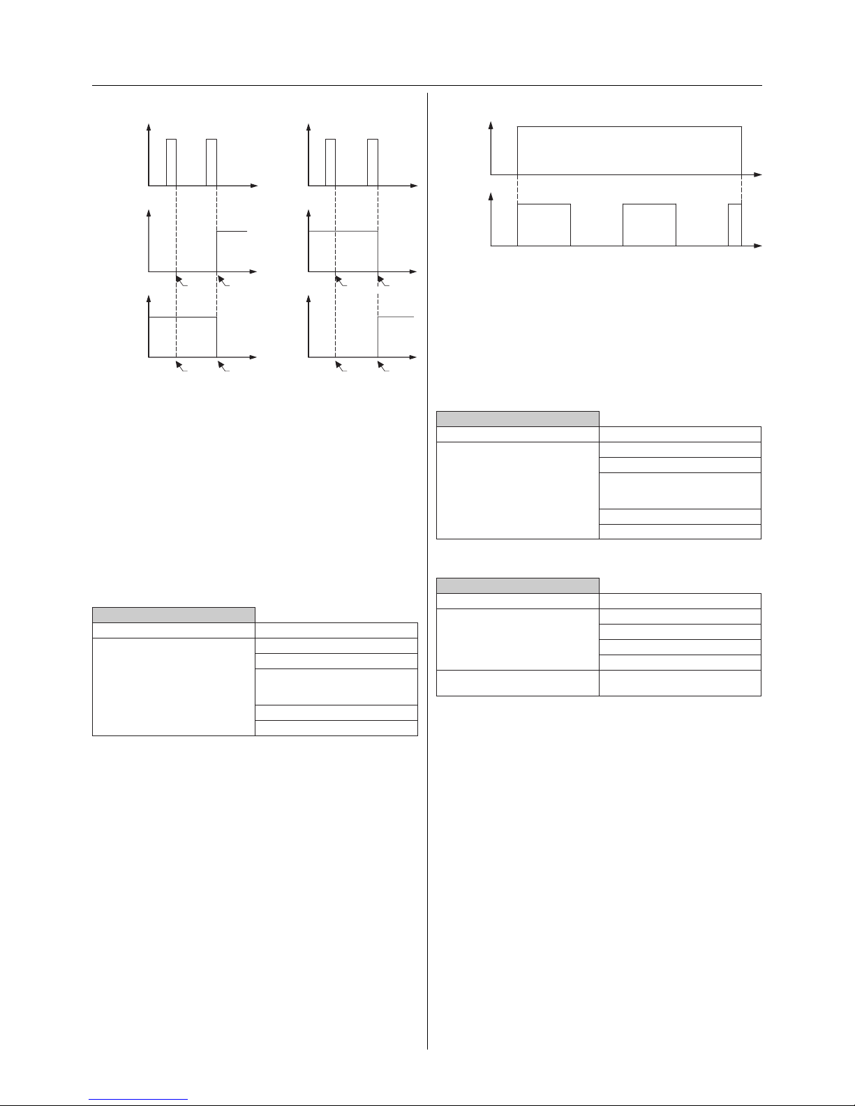
Switch (changeover contact for channel 1/2)
Status response
If two channels are combined into a changeover contact,
there is only one status feedback object when the status
response function is active.
This object always conveys the switching state of the
odd-numbered channel e.g. “1” (1= relay closed; 0= relay
opened).
Parameters
Per pair of channels: Select the relay mode “changeover
contact (channel 1: make contact / channel 2: break
contact)”
Channel X: General
Parameter Setting
Relay operation make contact
break contact
changeover contact (channel 1:
make contact / channel 2: break
contact)
ash for ON
ash for OFF
- Relay operation: ashing indicator
In the ashing indicator function, the relay opens and
closes automatically. A common ashing rate can be set for
all the channels via the “Flashing interval” parameter. The
frequency is calculated by multiplying a base value with a
factor.
Important
No short switching times may be parameterised
under load (see the technical data for the switch
output)
It can be selected whether the channel ashes for the value
“ON” (actuated) or “OFF” (not actuated). The value is the
product of combining the disable/higher priority function
with the switch object.
open
t
t
10
remains
open
is
closed
KNX
telegram
Relay status of
channel
A
closed
t
remains
closedisopened
open
t
1 0
KNX
telegram
Relay status of
channel A
closed
open
t
remains
open
is
closed
Relay status of
channel B
closed
t
remains
closed
is
opened
open
Relay status of
channel B
closed
Switching on Switching off
Page 7
7
Communication objects
The following communication objects can be selected:
Per channel:
Function Object name Type Prio Flags Behaviour
Channel X Switch object 1 bit Low CW Receive
Parameters
Per channel: Set the required relay operation mode.
Channel X: General
Parameter Setting
Relay operation make contact
break contact
changeover contact
ash for ON
ash for OFF
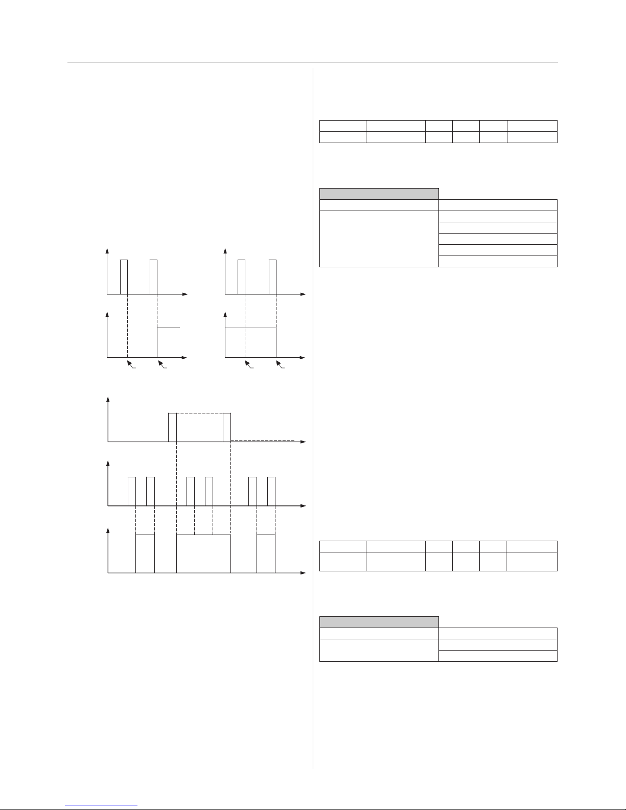
- Central switching function
The central switching function has its own communication
object (1 bit central object) It can be set for each channel of
the actuator whether and how the channel should react to
the central switch object.
Using the parameters, you can set whether only the state
“actuated” (make contact => closed and break contact =>
opened), only the state “not actuated” or both states of the
central switch object for the channel should be evaluated.
The central function has a low priority. Telegrams from
the central switch objects activate the set switching/time
functions and higher priority functions in the same way as
telegrams from the corresponding switch object.
The last telegram from the individual switch object or the
central object always activates the functions that have been
set for the channel.
Communication objects
The following communication objects can be selected:
Common for all channels
Function Object name Type Prio Flags Behaviour
Central
function
Central object 1 bit Low CW Receive
Parameters
Switch on the central switching function (active).
Central function
Parameter Setting
Central function is active
not active
Switching functions
- Switching
Binary bus telegrams (EIS1 telegrams, 1 bit) are received via the
“Switch object” and converted into switching states (relay open/
relay closed). The application changes the value of the “Switch
object” during operation. Reading out the “Switch object” via
the bus does not convey the status of the relay. The status
should always be read out via the “Status feedback object”.
The switching behaviour of the normal switch function can be modied by activating functions with a
higher priority (see ‘Priorities’).
Switch (make function)
Switch (break function)
After bus voltage recovery, the relay is closed in the “break
contact” mode and a status response telegram is generated
with the value “1” if the status response function is activated. In this case, a dierent response is carried out e.g. by
a higher priority function or due to the behaviour on bus
voltage recovery at the output.
Before triggering the relay, a check is made to determine
whether there is sucient energy to operate the relay. If
there is sucient energy, the relay immediately switches
to the parameterised state. Otherwise there is a delay until
sucient energy is available.
The xed relay positions (open, closed) within the other
functions are triggered directly. An inversion by the break
contact function is not carried out for xed relay positions.
open
t
t
10
remains
open
is
closed
KNX
telegram
Relay status
closed
Relay status
closed
t
remains
closedisopened
open
t
1 0
KNX
telegram
Switching on Switching off
t
1 0
t=0
KNX
telegram,
logic operation
ON
OFF
t
1 0
KNX
telegram,
switching
1 0 1 0
t
t
Status
actuated
not actuated
Page 8
8
Per channel:
Function Object name Type Prio Flags Behaviour
Channel X Switch object 1 bit Low CW Receive
Parameters
Per channel: Switch on the ON delay.
Channel X: General
Parameter Setting
ON delay switched on
switched o
Per channel: Set the ON delay.
Channel X: Times
Parameter Setting
Time base for ON delay - 100 ms
1 s
1 min
1 hr
Factor for ON delay
(1-255)
3
adjustable in single steps
ON delay is not retriggerable
retriggerable
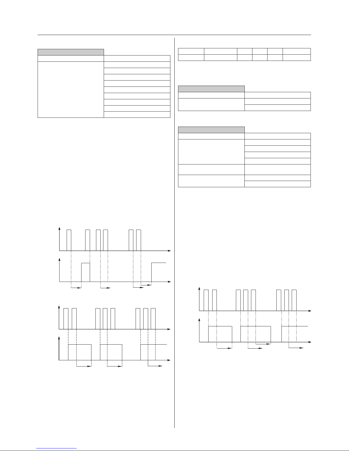
- OFF delay
The output is switched o without a delay. The delay can be
parameterised. The delay period is calculated by multiplying a base value with a factor. The set period can be dened
via parameter as “retriggerable” or “not retriggerable”. In
the case of retriggerable time delays, the delay is restarted
on receipt of a “0” telegram (switch object). If the delay is
not retriggerable, the relay is opened once the period has
elapsed.
If the output of the actuator is forced into a new switching
position by a higher priority function while a delay is still
running, the relay is switched without a delay.
Retriggerable OFF delay
t
t
1
t off
1 0 0 10
t off
10
t off t off
KNX
telegram
Status
actuated
not actuated
Per channel: Set the central switching function.
Central function
Parameter Setting
Channel X OFF at 0 or 1
ON at 0 or 1
ON at 0 / OFF at 1
OFF at 0 / ON at 1
OFF at 0 / no reaction at 1
ON at 0 / no reaction at 1
no reaction at 0 / OFF at 1
no reaction at 0 / ON at 1
no reaction at 0 or 1
Time functions
- ON delay
The output is switched on with a delay. The delay can be
parameterised. The delay period is calculated by multiplying a base value with a factor. The set period can be dened
via parameter as “retriggerable” or “not retriggerable”. In
the case of retriggerable time delays, the delay is restarted
on receipt of a “1” telegram (switch object). If the delay is
not retriggerable, the relay is opened once the period has
elapsed.
If the output of the actuator is forced into a new switching
position by a higher priority function while a delay is still
running, the relay is switched without a delay.
Retriggerable ON delay
Non-retriggerable ON delay
Actuated
The relay is closed in the make function. The relay is opened
in the break function.
Communication objects
The following communication objects can be selected:
t
t
1
t on
0 1 0 1 1
t on
t on t on
KNX
telegram
Status
actuated
not actuated
t
t
1
t off
1 0 0 10
t off
10
t off
KNX
telegram
Status
actuated
not actuated
Page 9
9
ON and OFF delay
Communication objects
The following communication objects can be selected:
Per channel:
Function Object name Type Prio Flags Behaviour
Channel X Switch object 1 bit Low CW Receive
Parameters
Per channel: Switch on the ON and OFF delay.
Channel X: General
Parameter Setting
ON delay switched on
switched o
OFF delay switched on
switched o
Per channel: Set the ON and OFF delay.
Channel X: Times
Parameter Setting
Time base for ON delay - 100 ms
1 s
1 min
1 hr
Factor for ON delay
(1-255)
3
adjustable in single steps
ON delay is not retriggerable
retriggerable
Time base for OFF delay - 100 ms
1 s
1 min
1 hr
Factor for OFF delay
(1-255)
120
adjustable in single steps
OFF delay is not retriggerable
retriggerable
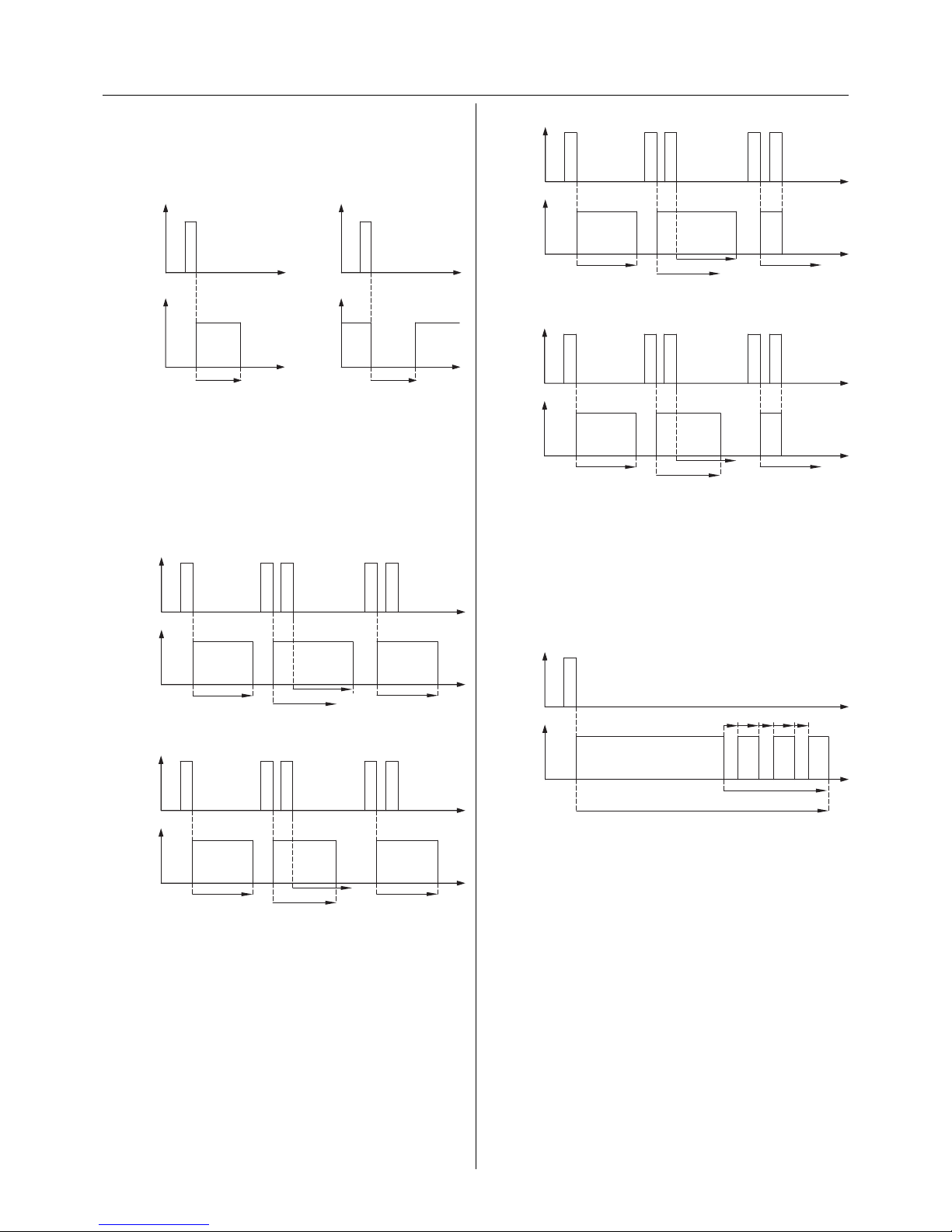
- Staircase lighting function (staircase timer)
In the staircase lighting function, once the device has been
switched on via the “Switch object”, it switches itself o automatically after an adjustable period. In the “make contact”
relay mode, the switch output is closed when the staircase
timer is activated. The relay is opened in the “break contact”
mode. In the relay mode “ash for ON”, the switch output
open
t
t
KNX
telegram,
switching
Relay status
closed
Relay status
closed
t
open
t
KNX
telegram,
switching
1 1
t on
t on
t off
t off
0
0
Make contact function Break contact function
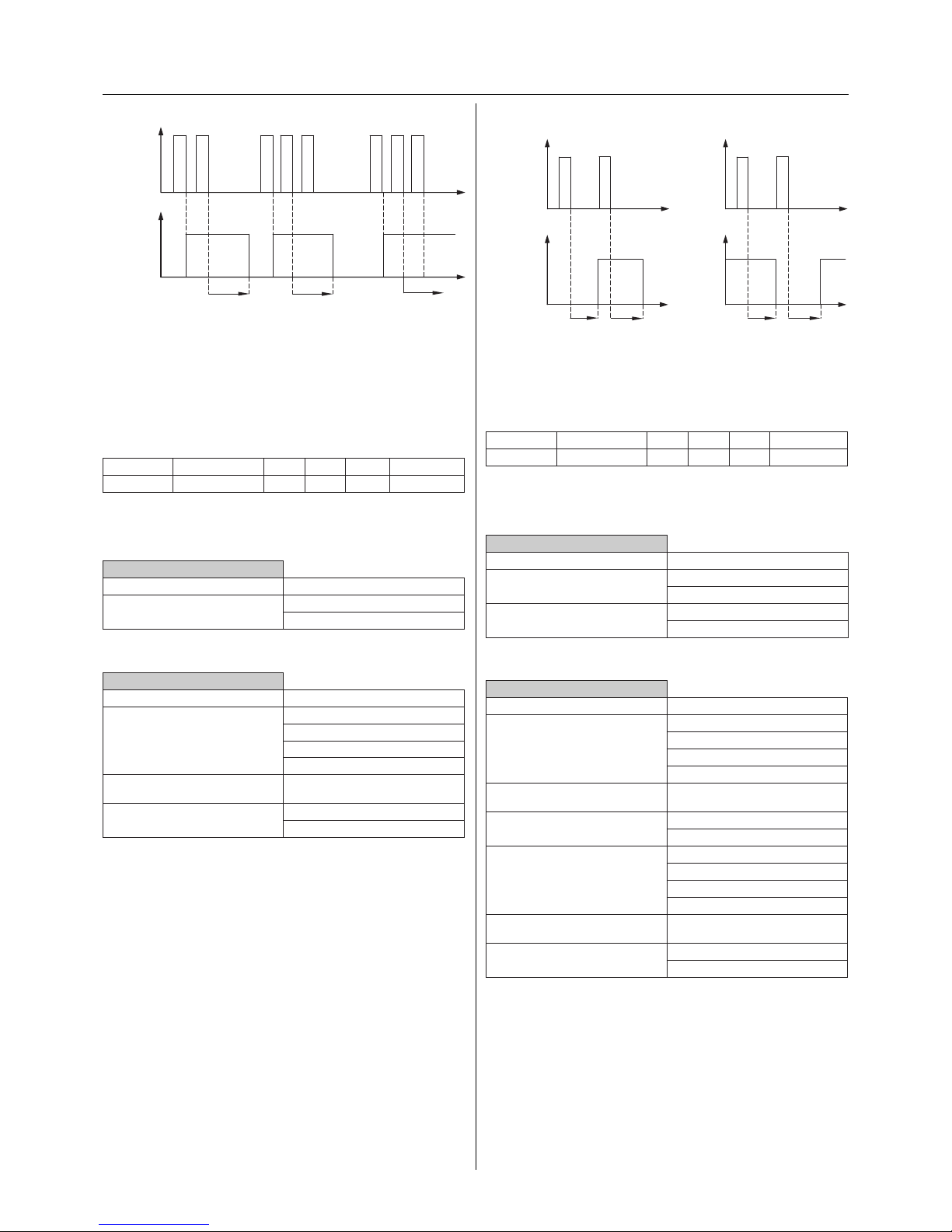
Non-retriggerable OFF delay
Actuated
The relay is closed in the make function. The relay is opened
in the break function.
Communication objects
The following communication objects can be selected:
Per channel:
Function Object name Type Prio Flags Behaviour
Channel X Switch object 1 bit Low CW Receive
Parameters
Per channel: Switch on the OFF delay.
Channel X: General
Parameter Setting
OFF delay switched on
switched o
Per channel: Set the OFF delay.
Channel X: Times
Parameter Setting
Time base for OFF delay - 100 ms
1 s
1 min
1 hr
Factor for OFF delay
(1-255)
120
adjustable in single steps
OFF delay is not retriggerable
retriggerable
- ON delay and OFF delay
The combination of an ON delay and an OFF delay results in
the output being switched on and o with a delay.
t
t
1
t off
1 0 0 10
t off
10
t off
KNX
telegram
Status
actuated
not actuated
Page 10
10
Retriggerable staircase lighting function with manual OFF function
Non-retriggerable staircase lighting function with manual OFF function
The staircase lighting function can indicate that the end of
the staircase timer is imminent by causing the luminaire
to icker. It is possible to select between one and three
warnings. It is possible to set the time (t warning) when
the warnings should start before the staircase timer has
elapsed. The length of the interruptions (t l) and the interval
between two warnings (t int) can also be set.
Staircase timer with prewarning
In the case of staircase lighting functions with a manual OFF function and active prewarning, the staircase
lighting function with prewarning is immediately
deactivated when an OFF telegram is received.
If the output of the actuator is brought into a new switching position by a function with a higher priority while the
staircase timer is active, the relay is immediately switched
to this position. The last switching telegram is stored and
any delay periods or staircase timers continue to run.
Switching functions and staircase lighting functions
cancel each other out i.e. they cannot be active at
the same time. If the staircase lighting function is parameterised, the channel only operates as a staircase
timer. If the staircase lighting function is not set, the
switching function is automatically active.
t
t
1 1 1
t staircase
t staircase
t staircase
10
t staircase
KNX
telegram
Status
actuated
not actuated
t
t
1 1 1
t staircase
t staircase
t staircase
10
t staircase
KNX
telegram
Status
actuated
not actuated
t
t
1
t staircase
KNX
telegram
Status
actuated
not actuated
t warning
t l
t int
t l
t int
t l
123
ashes while the staircase lighting function is active. In the
relay mode “ash for OFF”, the output ashes whenever the
staircase lighting function is not activated.
Staircase lighting function
The period (t staircase) is calculated by multiplying a base
value by a factor.
The settings “retriggerable” or “not retriggerable” dene
whether the staircase timer is restarted by means of a
further “1” telegram. If the staircase lighting function is
“retriggerable”, the period can be extended via the bus.
Retriggerable staircase lighting function without manual OFF function
Non-retriggerable staircase lighting function without manual OFF function
For the staircase lighting function, you can use the parameter “with / without manual OFF function” to set whether
the timer is switched o prematurely after a “0” telegram
is received or whether the “0” telegram is ignored and the
staircase timer continues to run.
open
t
t
KNX
telegram,
switching
Relay status
closed
Relay status
closed
t
open
t
KNX
telegram,
switching
1
t staircase
1
t staircase
Make contact function Break contact function
t
t
1 1 1
t staircase
t staircase
t staircase
10
t staircase
EIB
telegram
Status
actuated
not actuated
t
t
1 1 1
t staircase
t staircase
t staircase
10
t staircase
EIB
telegram
Status
actuated
not actuated
Page 11
11
Communication objects
The following communication objects can be selected:
Per channel:
Function Object name Type Prio Flags Behaviour
Channel X Switch object 1 bit Low CW Receive
Parameters
Per channel: Switch on the ON delay and staircase light-
ing function.
Channel X: General
Parameter Setting
ON delay switched on
switched o
Staircase lighting function switched on
switched o
Per channel: Set the ON delay.
Channel X: Times
Parameter Setting
Time base for ON delay - 100 ms
1 s
1 min
1 hr
Factor for ON delay
(1-255)
3
adjustable in single steps
ON delay is not retriggerable
retriggerable
Per channel: Set the staircase lighting function.
Channel X: Staircase timer
Parameter Setting
Base for staircase timer 100 ms
1 s
1 min
1 hr
Factor for staircase timer
(1-255)
85
adjustable in single steps
Staircase time is not retriggerable
retriggerable
Staircase timer with manual OFF
without manual OFF
Prewarning at end of staircase
time -
OFF
ON
Number of prewarnings 1
2
3
Prewarning time (1-255), factor
x 1 s
30
adjustable in single steps
Time for interruptions (1-20), factor
x 100 ms
5
adjustable in single steps
Time between prewarnings (1-255),
factor x 1 s
5
adjustable in single steps
Communication objects
The following communication objects can be selected:
Per channel:
Function Object name Type Prio Flags Behaviour
Channel X Switch object 1 bit Low CW Receive
Parameters
Per channel: Switch on the staircase lighting function.
Channel X: General
Parameter Setting
Staircase lighting function switched on
switched o
Per channel: Set the staircase lighting function.
Channel X: Staircase timer
Parameter Setting
Base for staircase timer 100 ms
1 s
1 min
1 hr
Factor for staircase timer
(1-255)
85
adjustable in single steps
Staircase time is not retriggerable
retriggerable
Staircase timer with manual OFF
without manual OFF
Prewarning at end of staircase
time -
OFF
ON
Number of prewarnings 1
2
3
Prewarning time (1-255), factor
x 1 s
30
adjustable in single steps
Time for interruptions (1-20), factor
x 100 ms
5
adjustable in single steps
Time between prewarnings (1-255),
factor x 1 s
5
adjustable in single steps
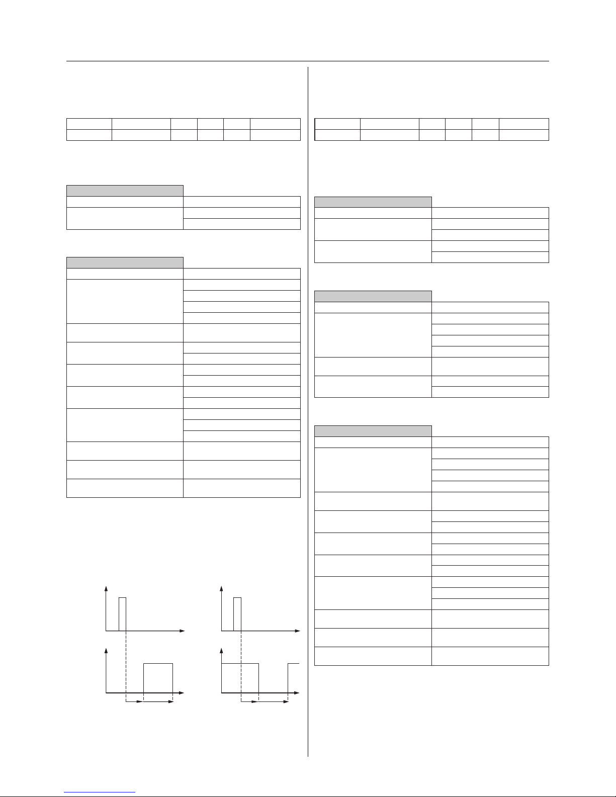
- ON delay and staircase lighting function
The combination of an ON delay with the staircase lighting
function results in the delayed start of the staircase lighting
function.
ON delay with staircase lighting function
open
t
t
EIB
telegram
Relay status
closed
Relay status
closed
t
open
t
EIB
telegram
1
t staircase
1
t staircase
t on
t on
Make contact function Break contact function
Page 12
12
Communication objects
The following communication objects can be selected:
Per channel:
Function Object name Type Prio Flags Behaviour
Channel X Switch object 1 bit Low CW Receive
Parameters
Per channel: Switch on the OFF delay and staircase
lighting function.
Channel X: General
Parameter Setting
OFF delay switched on
switched o
Staircase lighting function switched on
switched o
Per channel: Set the OFF delay.
Channel X: Times
Parameter Setting
Time base for OFF delay - 100 ms
1 s
1 min
1 hr
Factor for OFF delay
(1-255)
120
adjustable in single steps
OFF delay is not retriggerable
retriggerable
Per channel: Set the staircase lighting function.
Channel X: Staircase timer
Parameter Setting
Base for staircase timer 100 ms
1 s
1 min
1 hr
Factor for staircase timer
(1-255)
85
adjustable in single steps
Staircase time is not retriggerable
retriggerable
Staircase timer with manual OFF
without manual OFF
Prewarning at end of staircase
time -
OFF
ON
Number of prewarnings 1
2
3
Prewarning time (1-255), factor
x 1 s
30
adjustable in single steps
Time for interruptions (1-20), factor
x 100 ms
5
adjustable in single steps
Time between prewarnings (1-255),
factor x 1 s
5
adjustable in single steps
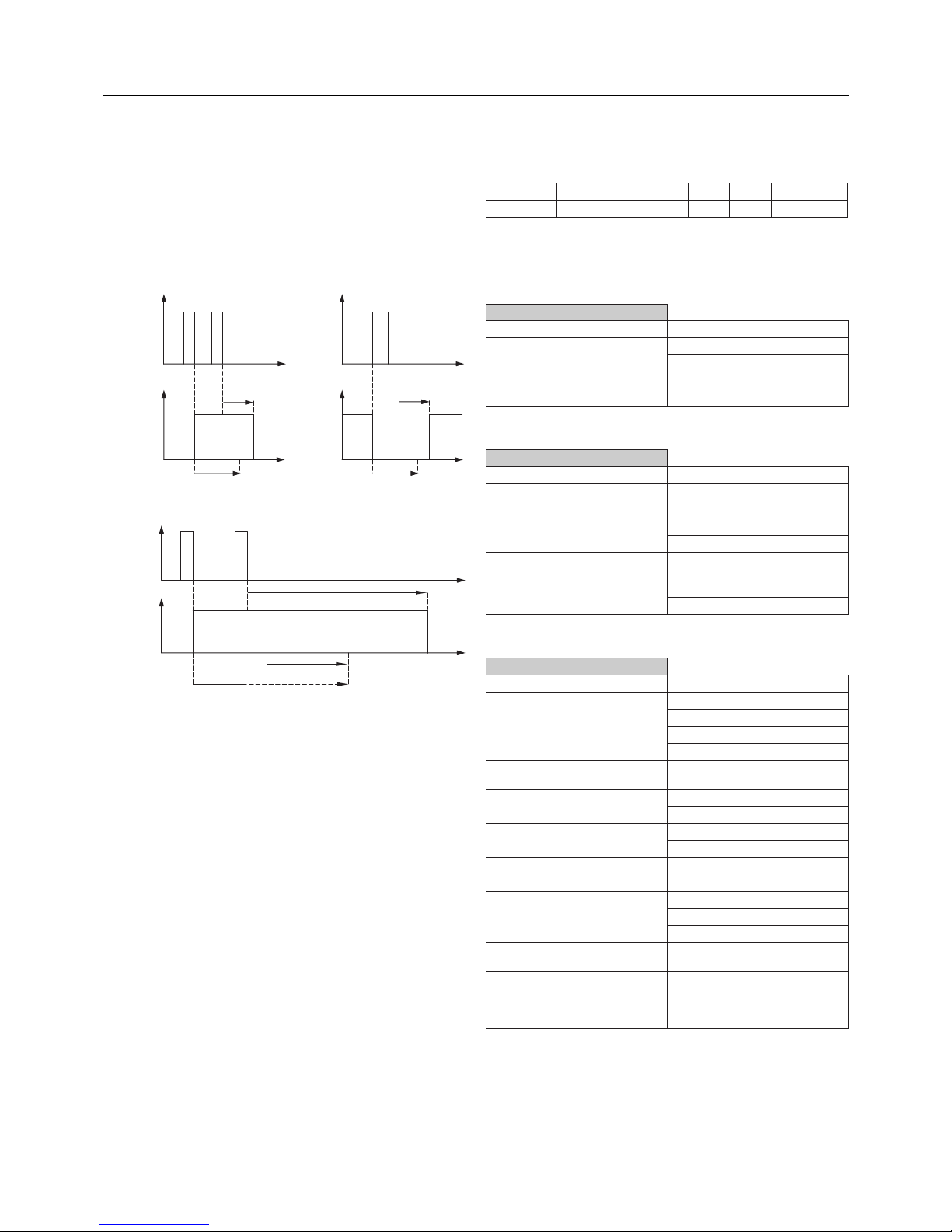
- OFF delay and staircase lighting function
The OFF delay can only be activated when a pure switching
function is selected or when combined with the setting
“staircase lighting function with manual OFF”. The parameters for the OFF delay are not displayed in the setting
“staircase lighting function without manual OFF”. The set
OFF delay is started on receipt of an OFF telegram while the
staircase timer is running.
Staircase lighting function with OFF delay
Staircase lighting function with prewarning and OFF delay
In the case of staircase lighting functions with a
manual OFF function and active prewarning, the
staircase lighting function with prewarning is immediately deactivated on receipt of an OFF telegram.
The OFF delay elapses. No prewarning takes place.
open
t
t
KNX
telegram
Relay status
closed
Relay status
closed
t
open
t
KNX
telegram
1
t staircase
1
0
0
t staircase
t off
t off
Make contact function Break contact function
t
t
1
t staircase
KNX
telegram
Status
actuated
not actuated
t warning
0
t off
Page 13
13
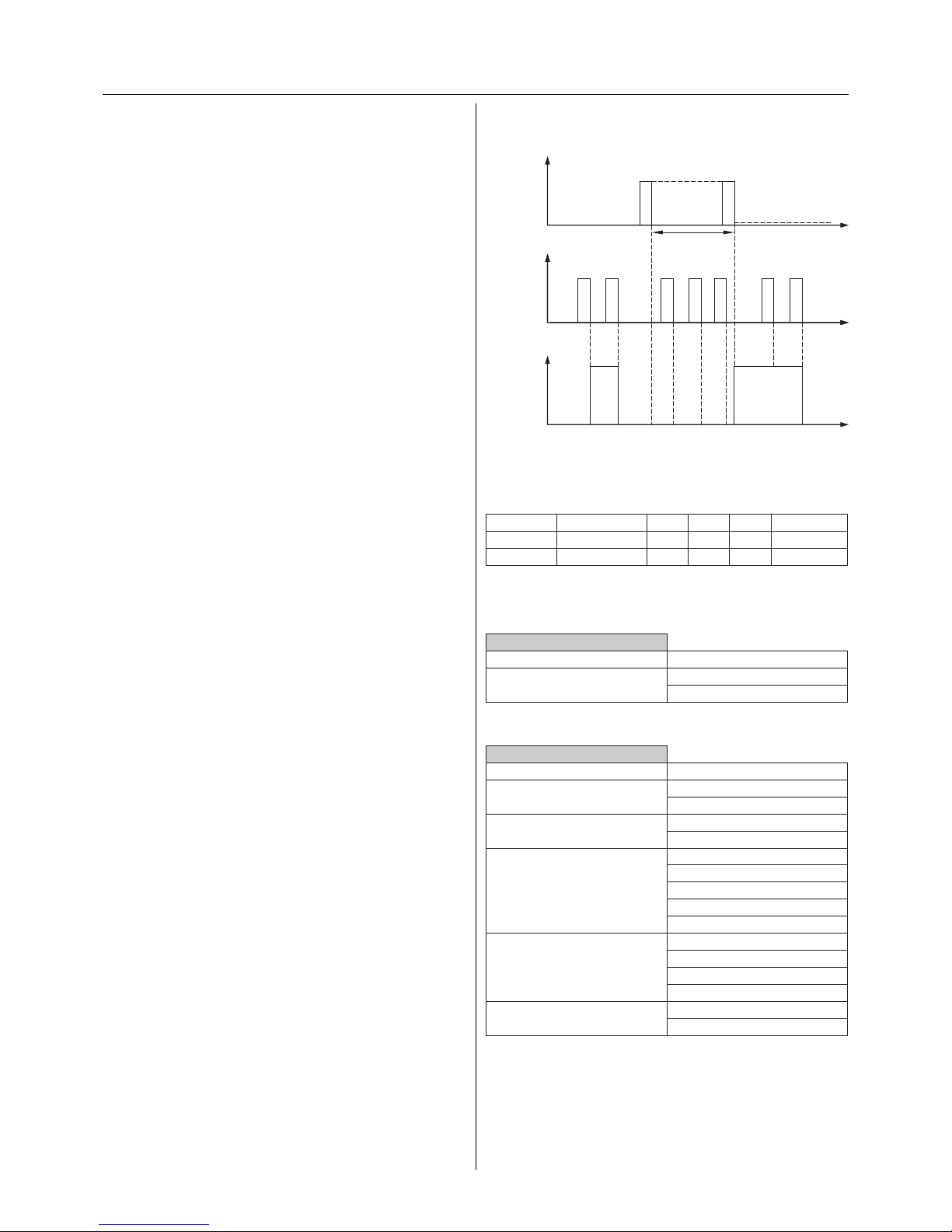
Disable function for: Disable object = 1; Value of disable object after bus
voltage recovery: 0; Reaction at blocking: no change; Reaction at activation: follows switch object
Communication objects
The following communication objects can be selected:
Per channel:
Function Object name Type Prio Flags Behaviour
Channel X Switch object 1 bit Low CW Receive
Channel X Disable object 1 bit Low CW Receive
Parameters
Per channel: Switch on the disable function.
Channel X: General
Parameter Setting
Disable function switched o
switched on
Per channel: Set the disable function.
Channel X: Disable
Parameter Setting
Disable function for Disable object = 0
Disable object = 1
Value of disable object after bus
voltage recovery
1
0
Reaction at blocking no change
changes state
actuated
not actuated
ashes
Reaction at activation no change
follows switch object
actuated
not actuated
Reaction at activation (with active
staircase lighting function)
follows switch object
not actuated
t
1 0
t=0
KNX
telegram,
disable object
ON
OFF
t
1 0
KNX
telegram,
switch object
1 0 1 0
t
1
disabled
Status
actuated
not actuated
Higher-level functions
With regard to the switching behaviour of the actuator, the
higher priority functions take precedence over the switching function, staircase lighting function and time delays. If
a higher priority function is active, changes to the switch
object no longer aect the relay output. The status of the
relay remains in the position which was preselected by the
higher priority function. Higher priority functions are carried out without a delay i.e. delay periods are not taken into
account when switched to a higher priority state.
There are three higher priority functions available: the
disable function, logic operations and the priority control
function. Logic operations and priority control functions
cancel each other out i.e. only one of the two functions can
be used per channel.
The logic operation or priority control function has a lower
priority than the disable function. If a logic operation and
the disable function occur at the same time, the disable
function takes priority. Each channel has an object for each
higher priority function (logic, priority or disable object).
All three functions are activated by means of parameters.
When switching between the functions, the parameter settings and communication objects of these
functions are modied by the ETS program. Linked
group addresses are deleted. For this reason, the
function should be dened rst.
- Disable function
The functionality of the selected switch actuator channel
can be deactivated with the help of the “Disable object”.
Telegrams via the “Switch object” or status changes from
the logic/priority function are no longer converted into
switching commands at the relay when the disable function is activated.
The disable function can be triggered by a “1” or by a “0”
telegram. (Disable object = 1 or disable object = 0).
Using the parameter “Value of disable object after bus voltage recovery”, you can dene whether the disable function
is only eective after receipt of a disable telegram via the
“Disable object” or immediately after a RESET.
With the parameter “Reaction at blocking”, the output is set
to the required position for the disable function.
Telegrams to the “Switch object” are received and the last
telegram is saved each time. When the disable function is
no longer active, it is possible to dene the relay state with
the parameter setting “Reaction at activation”.
Page 14
14
Parameters
Per channel: Switch on the ON/OFF delay, staircase
lighting function and disable function.
Channel X: General
Parameter Setting
Disable function switched o
switched on
ON delay switched on
switched o
OFF delay switched on
switched o
Staircase lighting function switched o
switched on
Per channel: Set the disable function.
Channel X: Disable
Parameter Setting
Disable function for Disable object = 0
Disable object = 1
Value of disable object after bus
voltage recovery
1
0
Reaction at blocking no change
changes state
actuated
not actuated
ashes
Reaction at activation no change
follows switch object
actuated
not actuated
Reaction at activation (with active
staircase lighting function)
follows switch object
not actuated
Per channel: Set the ON and OFF delay.
Channel X: Times
Parameter Setting
Time base for ON delay - 100 ms
1 s
1 min
1 hr
Factor for ON delay
(1-255)
3
adjustable in single steps
ON delay is not retriggerable
retriggerable
Time base for OFF delay - 100 ms
1 s
1 min
1 hr
Factor for OFF delay
(1-255)
120
adjustable in single steps
OFF delay is not retriggerable
retriggerable
Set the ashing interval for the device if required.
Flashing interval
Parameter Setting
Flashing interval base 100 ms
1 s
1 min
1 hr
Flashing interval factor [5-255] 10
adjustable in single steps
Important
No short switching times may be parameterised
under load (see the technical data for the switch
output)
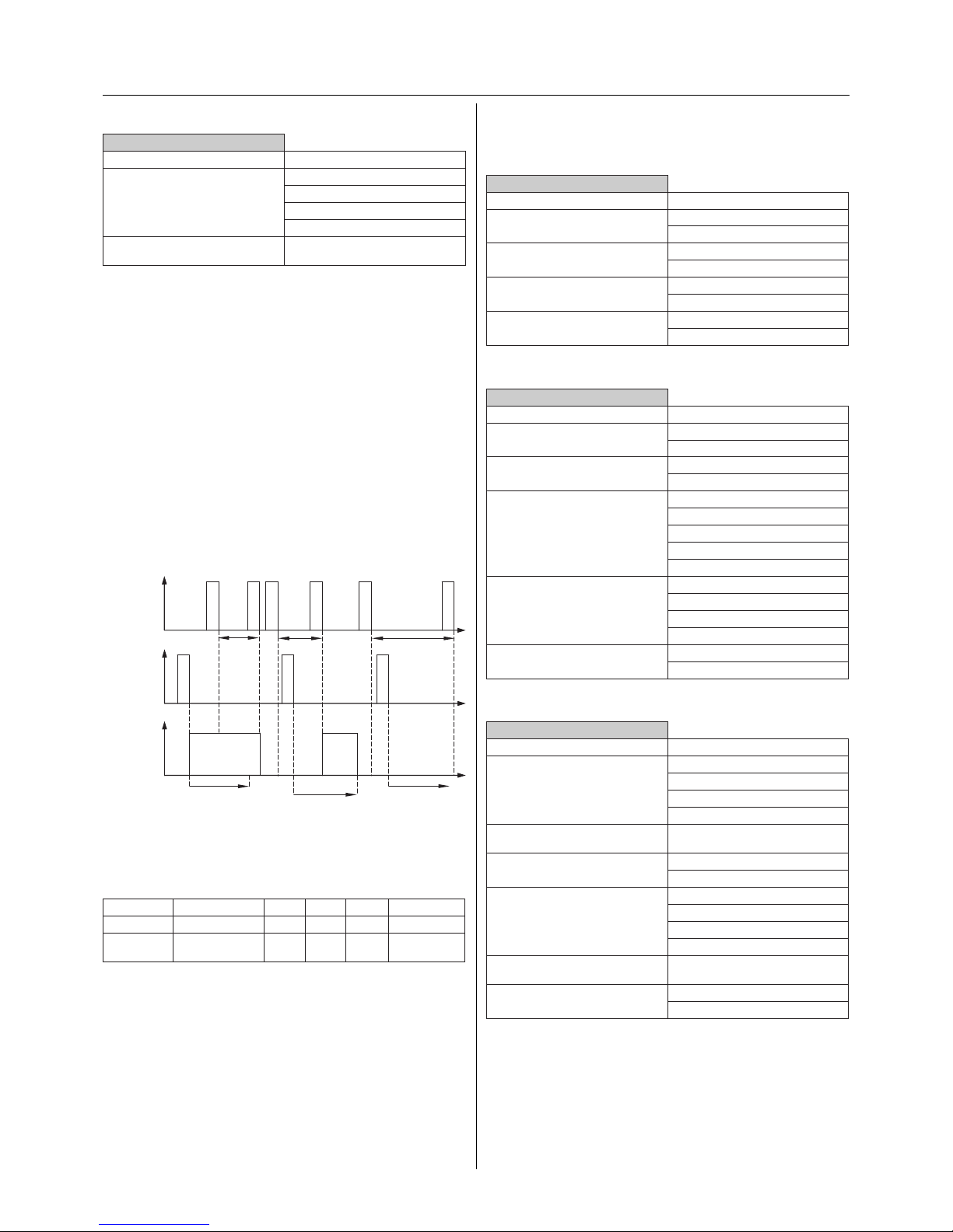
- Disable function with switching delay/staircase light-
ing function
When the disable function is activated, it always switches
in the required direction without a delay. When it is deactivated, the actuator likewise switches to the required state
without a delay. The last switching telegram is saved during
a disable function and any delay periods or staircase timers
continue to run.
Disable function for: Disable object = 1; Value of disable object after bus
voltage recovery: 0; Reaction at blocking: no change; Reaction at activation: follows switch object: Relay: make contact
Communication objects
The following communication objects can be selected:
Per channel:
Function Object name Type Prio Flags Behaviour
Channel X Switch object 1 bit Low CW Receive
Channel 1,
2,...
Disable object 1 bit Low CW Receive
KNX
telegram,
switch object
t
t
Relay status
closed
1
open
1
t staircase
t staircase
1
t staircase
KNX
telegram,
disable object
t
1 0 1 01
0
disabled
disabled disabled
Page 15
15
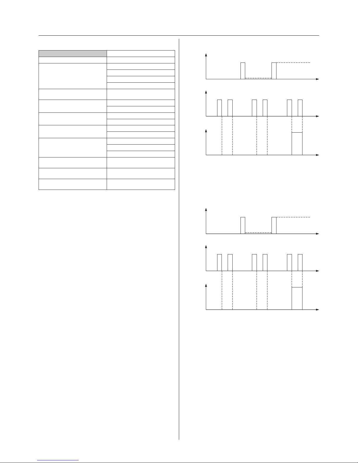
AND logic operation; Value of the logic object after bus voltage recovery:
1; Relay: make contact
The logic object is preassigned the value “1” after a RESET.
Switching can therefore be carried out as usual via the
switch object. The closing lock-out is only active after the
receipt of a “0” telegram via the logic object.
AND logic operation; Value of the logic object after bus voltage recovery:
0; Relay: make contact
The parameter setting causes the “Logic object” to be set to
the value “0”. After a RESET, the actuator will not switch the
output in the “make contact” mode nor with these settings,
until a “1” telegram has been received at the “Logic object”.
t
0 1
ON
OFF
t=0
KNX
telegram,
logic operation
t
0
0 0
KNX
telegram,
switching
111
Status
actuated
not actuated
t
0 1
ON
OFF
t=0
KNX
telegram,
logic operation
t
0
0 0
KNX
telegram,
switching
111
Status
actuated
not actuated
Per channel: Set the staircase lighting function.
Channel X: Staircase timer
Parameter Setting
Base for staircase timer 100 ms
1 s
1 min
1 hr
Factor for staircase timer
(1-255)
85
adjustable in single steps
Staircase time is not retriggerable
retriggerable
Staircase timer with manual OFF
without manual OFF
Prewarning at end of staircase
time -
OFF
ON
Number of prewarnings 1
2
3
Prewarning time (1-255), factor
x 1 s
30
adjustable in single steps
Time for interruptions (1-20), factor
x 100 ms
5
adjustable in single steps
Time between prewarnings (1-255),
factor x 1 s
5
adjustable in single steps
- Logic operations
With this functionality, the “Switch object” can be logically
linked with the “Logic object”. An AND or OR logic operation
can be set. A parameter denes which value is preassigned
to the logic object after bus voltage recovery.
For example, if the OR logic object is preset to “1” after bus
voltage recovery, the output remains switched on until a
“0” telegram has been received at the “Logic object”. Any
parameterised reaction after bus voltage recovery is only
adopted once the logic operation has nished.
The logic function has a high priority. The actuator will thus
always be set according to the logic result of the higher priority function and not the status of functions with a lower
priority.
AND logic operation
If the “Logic object” is set to “1”, switching can be carried
out as usual via the address of the “Switch object”. Any set
delay periods and staircase timers are followed. Switching
o via the “Logic object” takes place immediately (object
with higher priority). An OFF delay is no longer carried out.
If the “Logic object” is set to “1” again by a telegram, the
output is also switched without a delay when the ON delay
is activated.
Example:
A closing lock-out can be implemented with an AND logic
operation. This means that it is not possible to switch on
the output via the “Switch object” while the value of the
“Logic object” remains set to “0”. If the value of the “Switch
object” is set to “1”, the output is switched on automatically
following a change in the value of the logic object from “0”
to “1” (output is set).
Page 16
16
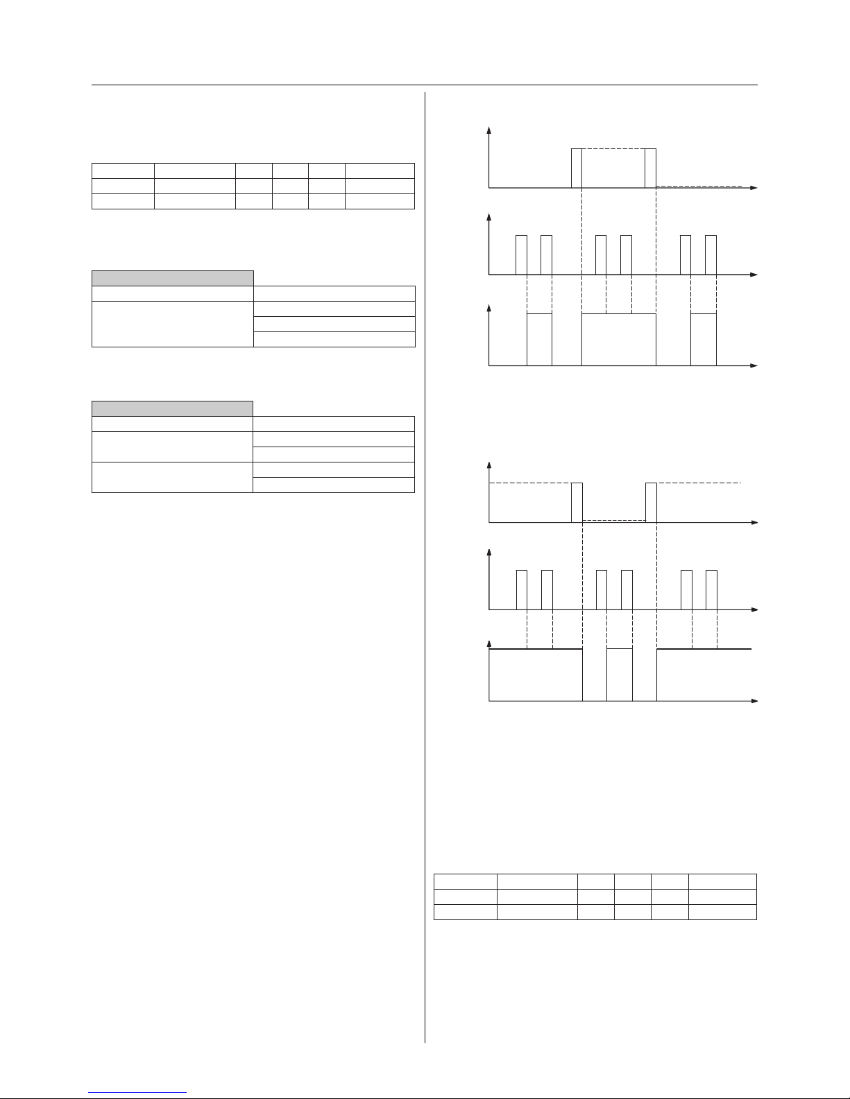
OR logic operation; Value of logic object after bus voltage recovery: 0;
Relay: make contact
The relay can only be opened via the “Switch object” once a
“0” telegram has been received via the “Logic object”.
OR logic operation; Value of logic object after bus voltage recovery: 1;
Relay: make contact
The logic object is preassigned the value “1” after a
RESET. The actuator will immediately switch on the
output in the “make contact” mode. The OR logic
function is only reset by a “0” telegram at the logic
object.
Communication objects
The following communication objects can be selected:
Per channel:
Function Object name Type Prio Flags Behaviour
Channel X Switch object 1 bit Low CW Receive
Channel X Logic object 1 bit Low CW Receive
t
1 0
t=0
KNX
telegram,
logic operation
ON
OFF
t
1 0
KNX
telegram,
switching
1 0 1 0
t
Status
actuated
not actuated
t
10
t=0
KNX
telegram,
logic operation
ON
OFF
t
1 0
KNX
telegram,
switching
1 0 1 0
t
ON
Status
actuated
not actuated
Communication objects
The following communication objects can be selected:
Per channel:
Function Object name Type Prio Flags Behaviour
Channel X Switch object 1 bit Low CW Receive
Channel X Logic object 1 bit Low CW Receive
Parameters
Per channel: Switch on the logic operation.
Channel X: General
Parameter Setting
Priority function none
Logic operation
Priority control
Switch on the AND logic operation and set the logic
behaviour after a RESET.
Channel X: Logic function
Parameter Setting
Type of logic operation OR
AND
Value of logic object after bus
voltage recovery
1
0
OR logic operation
While the “Logic object” has the value “0”, switching can be
carried out as usual via the address of the “Switch object”.
Any set delay periods are still valid. The closing of the relay
is carried out immediately via a “1” telegram to the “Logic
object” (object with higher priority). A delay is no longer
carried out. If the value of the “Logic object” is then set to
“0” again, the actuator immediately switches to the required state.
Example:
An opening lock-out or central ON function (e.g. lighting
for cleaning buildings) can be implemented with an OR
logic operation. If the value of the “Switch object” is also set
locally to “1”, the relay remains closed when the opening
lock-out is removed (value of the logic object changes from
“1” to “0”).
Page 17
17
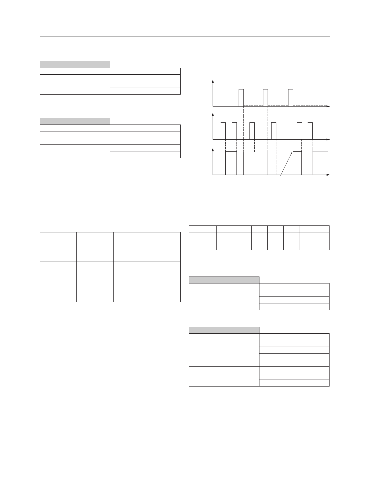
The function of the priority control after bus voltage recovery can be dened by means of a further parameter. The
output can be “actuated with priority”, “not actuated with
priority” or no active priority can be selected.
Priority control
Communication objects
The following communication objects can be selected:
Per channel:
Function Object name Type Prio Flags Behaviour
Channel X Switch object 1 bit Low CW Receive
Channel X Priority control
object
2 bit Low CW Receive
Parameters
Per channel: Switch on the priority control function.
Channel X: General
Parameter Setting
Priority function none
Logic operation
Priority control
Set the priority control function.
Channel X: Priority control
Parameter Setting
Reaction after priority no change
follows switch object
actuated
not actuated
Function of priority after bus voltage recovery
no active priority
actuated with priority
not actuated with priority
t
11 10
t=0
KNX
telegram,
priority
control
t
0
t
1 1
KNX
telegram,
switching
10
0
Status
actuated
not actuated
With
priority On
With
priority Off
01
00
Prioriry control
deactivated
Reaction after
priority control:
follows switch object
Parameters
Per channel: Switch on the logic operation.
Channel X: General
Parameter Setting
Priority function none
Logic operation
Priority control
Switch on the OR logic operation and set the logic
behaviour after a RESET.
Channel X: Logic operation
Parameter Setting
Type of logic operation OR
AND
Value of logic object after bus
voltage recovery
1
0
- Priority control
There is a 2 bit priority object in addition to the 1 bit switch
object. The switch actuator channel is switched to high
priority switching states (relay opened / relay closed) with
the 2 bit telegram. If the 2 bit priority object receives a telegram whose rst bit (bit 1) has the value ON “1”, the priority
control function is active. In this case, the switch actuator
switches to the state that was dened by the second bit (bit
0) of the telegram.
Bit 1 Bit 0 Function
1 1 Switched on with priority
(output actuated)
1 0 Switched o with priority (output
not actuated)
0 1 Priority control function not
active (output behaves according to parameter “Reaction after
priority”)
0 0 Priority control function not
active (output behaves according to parameter “Reaction after
priority”)
Bit 0=1 leads to the closing of the relay in the “make
contact” relay mode and to the opening of the relay in the
“break contact” relay mode.
Bit 0=0 leads to the output being switched o in the “make
contact” relay mode and to the output being switched on
in the “break contact” relay mode.
If the switch object receives switching telegrams during a
priority control function, the last telegram is stored each
time and is evaluated, if necessary, when the priority function is removed (according to the parameter settings).
Using the parameter “Reaction after priority”, you can set
how the respective channel should behave when the priority function is removed (rst bit (bit 1) is set to zero “0”). The
actuator can be switched on or o (actuated/not actuated),
can follow the current state of the switch object or retain
the current state (no change).
When the staircase lighting function is active, there are
fewer options available for selection.
Priority control is carried out without a delay.
Page 18
18
Per scene: Set the actuator channels.
Scene 1-8
Parameter Setting
Channel 1 ON
no change
OFF
Channel 2 (only when channel 1
not a changeover contact)
ON
no change
OFF
... ...
Channel X ON
no change
OFF
Channel X+1 (only when channel X
not a changeover contact)
ON
no change
OFF
- Status information (status response)
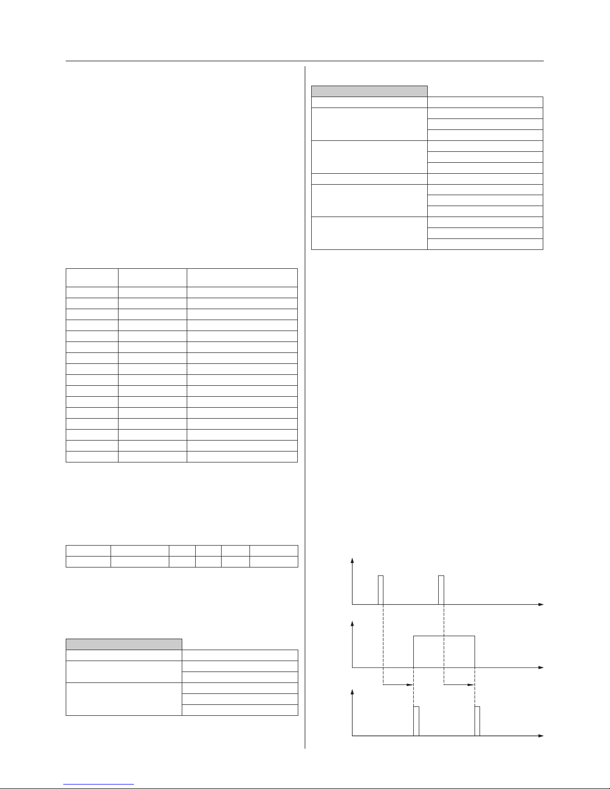
The status of the output can be read via its own communication object or actively sent. This means that the status
of the relay is available as a telegram on the bus after each
switching process. The value of the “Status feedback object”
always conveys the current status of the relay. When the
relay is closed, the value is “1” while the value is “0” when
the relay is opened, regardless of the relay operation mode.
After bus voltage recovery, a status feedback telegram with
the value “1” is sent via the “Status feedback object” after
approx. 17 s when the relay is closed and the active status
response function is switched on. When the contact is
opened, no “0” telegrams are generated.
If two channels are combined into a changeover contact,
there is only one status feedback object.
Manual operations (for 2-gang and 4-gang switch
actuators) on the device are not recognised. The status therefore no longer corresponds to the status of
the output. The correct status is only available again
after a switching operation via the bus.
The passive status object conveys the status of the relay at
any instant (e.g. for visualisation programs which actively
read out the status).
Active feedback with a parameterised ON and OFF delay
KNX
telegram
t
t
t
Relay status
closed
1
1
0
t on t o
0
KNX
telegram,
status feedback
open
Scenes
- Scene
The scene function of the switch actuator has an 8 bit scene
object. Using a parameter, you can dene for each scene
whether the scene should be inactive, active or active with
a memory function for new actuator states. A parameter
window appears for each active scene where the settings
can be carried out. 8 independent values can be stored for
each channel. When the scene is retrieved, it can be specied that the channel switches on, switches o or does not
change its state.
A scene is activated when it receives its scene number (1
byte value starting with “1”) at the scene object. If a scene is
parameterised with a memory function, the storing of the
current channel values is carried out using the object value
of the scene (scene number) + 128 (see table).
Scene Object value
(scene number)
Function
1 0 Retrieve scene 1
1 128 Save scene 1
2 1 Retrieve scene 2
2 129 Save scene 2
3 2 Retrieve scene 3
3 130 Save scene 3
4 3 Retrieve scene 4
4 131 Save scene 4
5 4 Retrieve scene 5
5 132 Save scene 5
6 5 Retrieve scene 6
6 133 Save scene 6
7 6 Retrieve scene 7
7 134 Save scene 7
8 7 Retrieve scene 8
8 135 Save scene 8
The scene function has likewise a low priority. Its behaviour
in combination with other functions corresponds to the
behaviour of the central function.
Communication objects
The following communication objects can be selected:
Function Object name Type Prio Flags Behaviour
Scene Scene object 1 byte Low CW Receive
Parameters
Common for all scenes: Activate the scenes.
Dene for Scene 1-8:
not active / retrievable / retrievable and storable.
General scene
Parameter Setting
Scenes are not active
active
Scene 1-8 is not active
retrievable
retrievable and storable
Page 19
19
Communication objects
The following communication objects can be selected:
Per channel:
Function Object name Type Prio Flags Behaviour
Channel X Status object 1 bit Low CR Receive
Channel X Status feedback
object
1 bit Low CT Transmit
Parameters
Per channel: Switch on the active status response or
passive status information.
Channel X: General
Parameter Setting
Status information switched o
active status feedback object
passive status object
Page 20

 Loading...