

Page 1
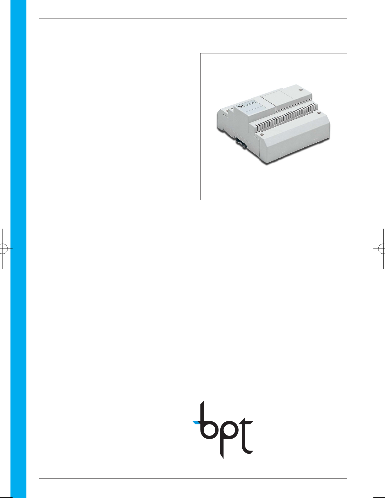
IT/200
Page 2
Page 3
1
ITALIANO
ENGLISHDEUTSCHFRANÇAISESPAÑOLPORTUGUÊS
ISTRUZIONI
INSTRUCTIONS
ANLEITUNG
INSTRUCTIONS
INSTRUCCIONES
INSTRUÇÕES
IT/200
INTERFACCIA TELEFONICA
TELEPHONE INTERFACE
TELEFONSCHNITTSTELLE
INTERFACE TELEPHONIQUE
INTERFAZ TELEFONICO
INTERFACE TELEFONICA
Page 4
2
Page 5
INDICE
3
ITALIANO
Istruzioni per l’installatore
Generalità . . . . . . . . . . . . . . . . . . . . . . . . .4
Avvertenze . . . . . . . . . . . . . . . . . . . . . . . .5
Installazione . . . . . . . . . . . . . . . . . . . . . . .6
Collegamenti . . . . . . . . . . . . . . . . . . . . . . .7
Messa in funzione . . . . . . . . . . . . . . . . . . .8
Programmazione . . . . . . . . . . . . . . . . . . . .9
- Configurazione di default . . . . . . . . . . . .9
- Ingresso ed uscita dalle
operazioni di programmazione . . . . . . .9
- Modalità segreto di conversazione . . . .9
- Durata conversazione citofonica . . . . .10
- Modalità analogico o codificato . . . . . .10
- Codice IT/200 in formato
blocco/utente ed impostazione
modo codificato . . . . . . . . . . . . . . . . . .11
- Codice IT/200 in formato progressivo
ed impostazione modo codificato . . . .11
- Durata comando apriporta . . . . . . . . . .12
- Modalità riconoscimento flash . . . . . . .12
- Intercettazione flash . . . . . . . . . . . . . . .13
- Tipo di monitor
da abbinare al telefono . . . . . . . . . . . .13
- Ripristino della
configurazione di default . . . . . . . . . . .14
Caratteristiche tecniche . . . . . . . . . . . . . .15
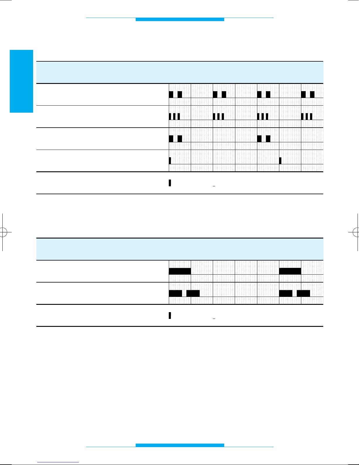
Toni e ritmi . . . . . . . . . . . . . . . . . . . . . . . .16
- Toni di segnalazione . . . . . . . . . . . . . .16
- Ritmi di chiamata . . . . . . . . . . . . . . . . .16
Istruzioni per l’utente
Glossario . . . . . . . . . . . . . . . . . . . . . . . . .17
Funzioni . . . . . . . . . . . . . . . . . . . . . . . . . .18
- Chiamata su linea urbana . . . . . . . . . .18
- Risposta alle chiamate in arrivo . . . . . .18
- Risposta a chiamata da posto
esterno ed apertura della porta . . . . . .18
- Autoinserimento su posto esterno . . . .19
- Cambio interlocutore . . . . . . . . . . . . . .19
- Chiamata portiere . . . . . . . . . . . . . . . .19
- Comando ausiliario/luce scale
da telefono . . . . . . . . . . . . . . . . . . . . . .20
- Disabilitazione avviso acustico
di chiamata in arrivo . . . . . . . . . . . . . .20
- Accesso ai servizi in DTMF
della compagnia telefonica . . . . . . . . .20
- Funzioni ottenibili con l’utilizzo
del telefono bpt
e con telefoni standard . . . . . . . . . . . .21
Page 6
4
ITALIANO
GENERALITÀ
L’interfaccia telefonica permette il collegamento di un apparecchio telefonico alla
linea videocitofonica e citofonica serie 200
e serie 100, sia essa codificata o meno.
Permette l’utilizzo, oltre al telefono bpt, di
normali apparecchi telefonici decadici o
DTMF, cordless, segreteria telefonica, modem, PABX, ecc.
L’apparecchio consente anche di inviare
chiamate ad un centralino di portineria di
tipo analogico o digitale e di comandare l’apriporta, luci scale centralizzato, ecc.
L’apparecchio, realizzato in un contenitore
DIN a 8 moduli, è composto da un circuito
stampato di base e da una scheda contenente i dip-switch per la programmazione e
la selezione della tipologia d’impianto.
Funzioni base
• Accesso diretto alla linea urbana.
• Collegamento al sistema videocitofonico
serie 200 con funzione di autoinserimento
(se abbinato al modulo monitor).
• Collegamento al sistema videocitofonico
serie 100.
• Collegamento al sistema citofonico con o
senza segreto di conversazione.
• Segreto di conversazione per impianti
BPT.
• Interfaccia codificata integrata.
• Comunicazione telefonica anche in man-
canza di alimentazione da rete.
• Chiamata diversificata da posto
esterno/linea telefonica.
• Comando apriporta.
• Comando ausiliario/luce scale.
• Chiamata portiere.
• Messa in attesa comunicazione (urba-
na/citofonica).
• Protezione linea telefonica.
• Programmazione dell’apparecchio median-
te telefono.
• Alimentazione da rete elettrica.
Page 7
5
ITALIANO
AVVERTENZE
Leggere attentamente le avvertenze contenute nel seguente manuale in quanto forniscono importanti indicazioni riguardanti la
sicurezza d’uso, d’installazione e manutenzione.
Dopo aver tolto l’imballaggio assicurarsi
dell’integrità dell’apparecchio.
Gli elementi dell’imballaggio (sacchetti in
plastica, polistirolo espanso, ecc.) non
devono essere lasciati alla portata dei bambini in quanto potenziali fonti di pericolo.
Lo smaltimento degli imballi deve essere
effettuato nel rispetto delle norme vigenti.
L’esecuzione dell’impianto deve essere
rispondente alle norme di sicurezza vigenti.
Non far passare i cavi telefonici in percorsi
comuni a quelli dei cavi elettrici.
Installare il centralino in ambienti non polverosi, lontano da apparecchiature che possano generare disturbi elettrici di alta frequenza quali saldatrici, motori elettrici, forni
a microonde, condizionatori d’aria, ecc.
E’ opportuno prevedere a monte dell’alimentatore un appropriato interruttore di
sezionamento e protezione.
Prima di collegare l’apparecchio accertarsi
che i dati di targa siano rispondenti a quelli
della rete di distribuzione.
Questo apparecchio dovrà essere destinato
unicamente all’uso per il quale è stato espressamente concepito; qualunque uso diverso è
da considerarsi improprio e pericoloso.
Il costruttore non può essere considerato
responsabile per eventuali danni derivanti
da usi impropri, erronei ed irragionevoli.
Prima di effettuare qualunque operazione di
pulizia o di manutenzione, disinserire l’apparecchio dalla rete di alimentazione elettrica, aprendo l’interruttore dell’impianto.
In caso di guasto e/o cattivo funzionamento
dell’apparecchio, scollegarlo dall’alimentazione e non manometterlo.
Per l’eventuale riparazione rivolgersi solamente ad un centro di assistenza tecnica
autorizzato dal costruttore.
Il mancato rispetto di quanto sopra può
compromettere la sicurezza dell’apparecchio.
L’installatore deve assicurarsi che le informazioni per l’utente, dove previste, siano
presenti sugli apparecchi.
Tutti gli apparecchi costituenti l’impianto
devono essere destinati esclusivamente per
l’uso per cui sono stati concepiti.
Page 8
6
ITALIANO
INSTALLAZIONE
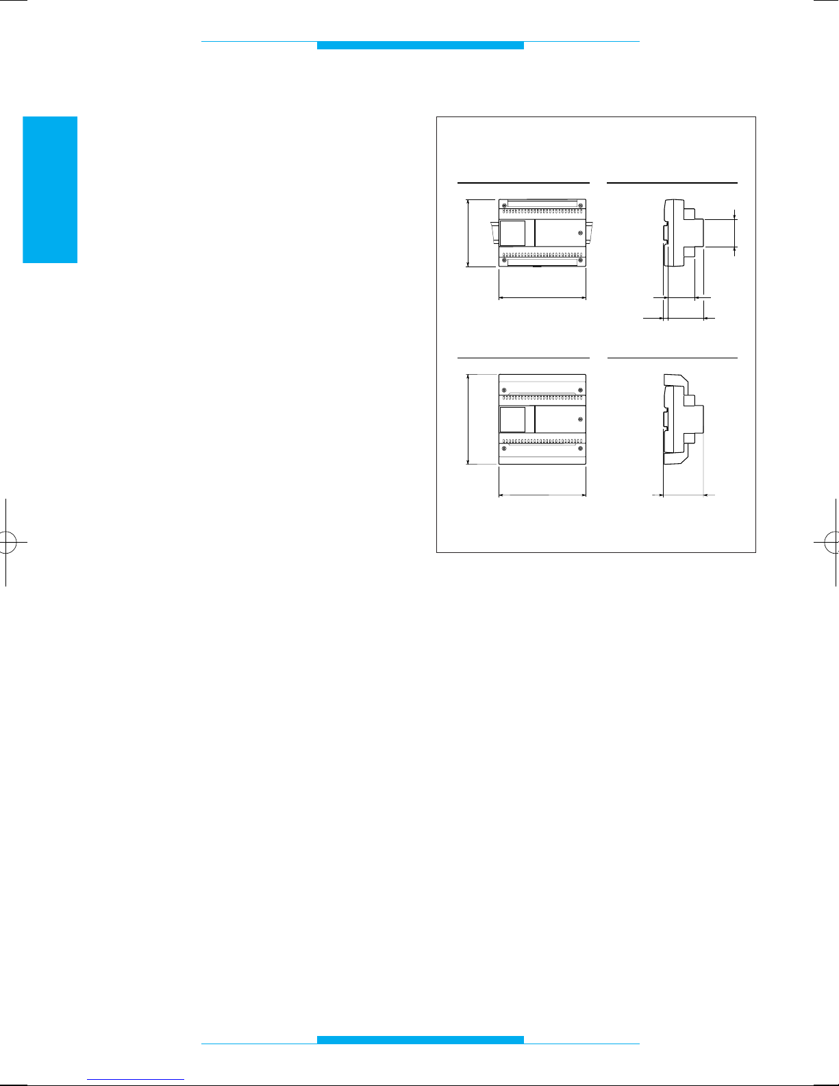
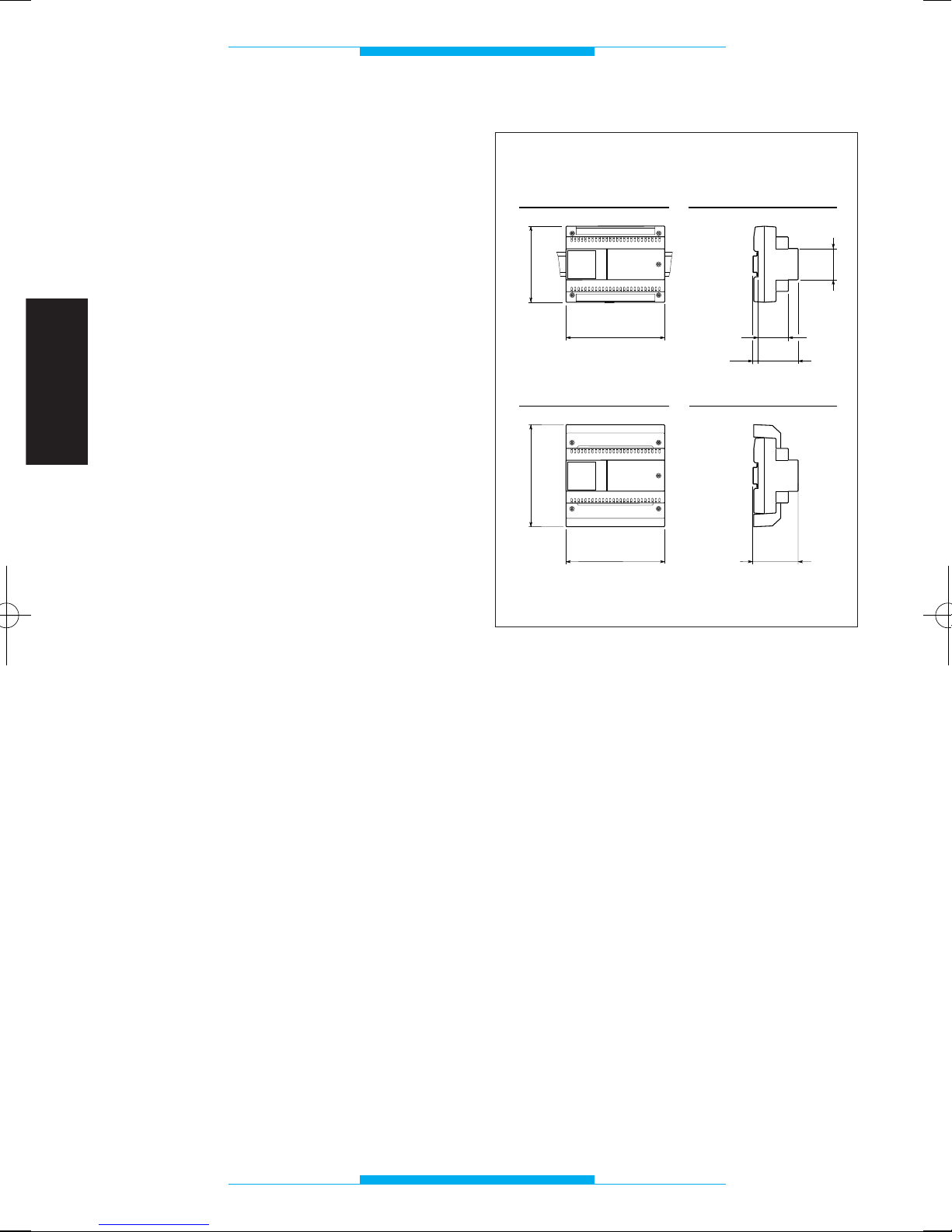
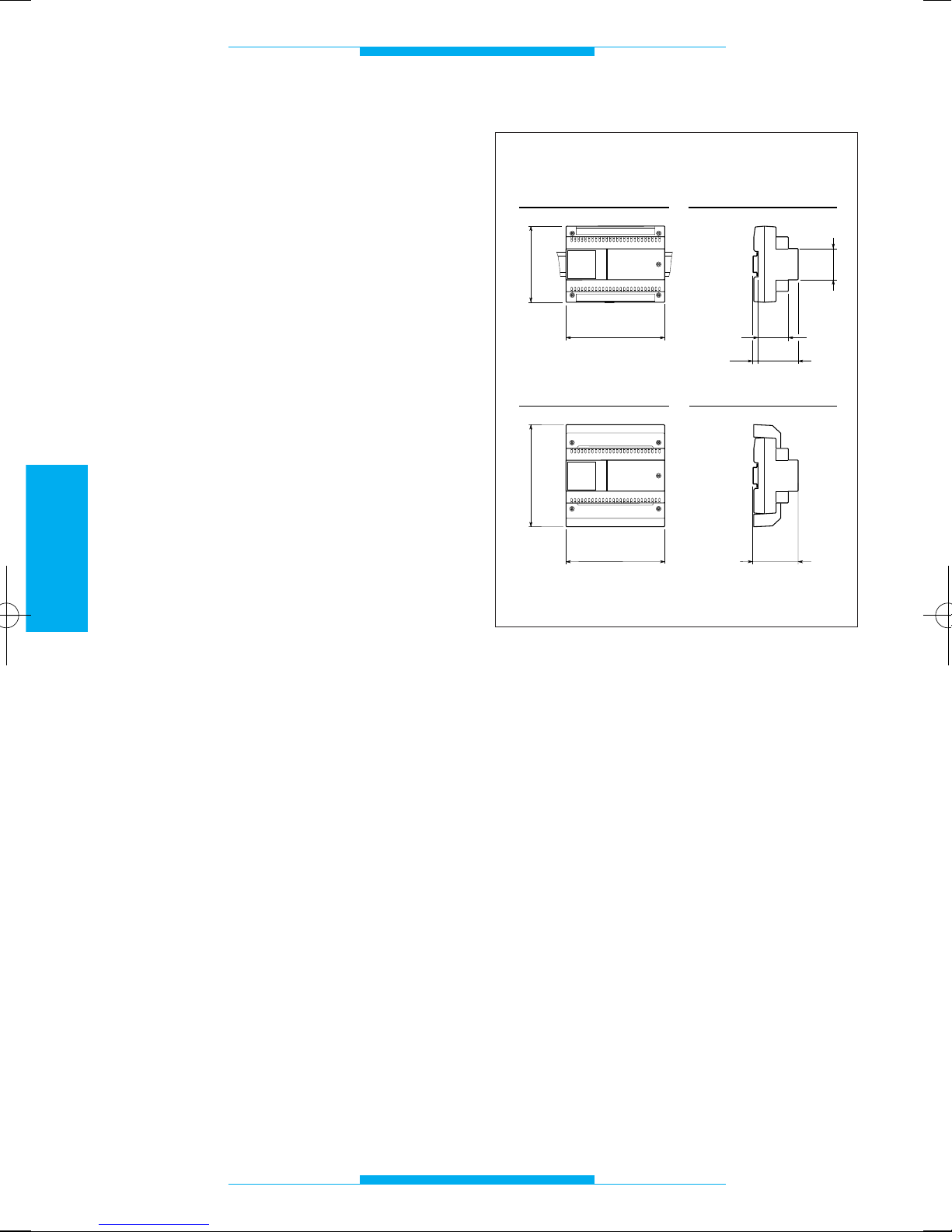
L’apparecchio, realizzato in un contenitore
da 8 unità basso, può essere installato
senza coprimorsetti in scatole munite di
guida DIN (EN 50022).
Per le dimensioni di ingombro vedere la fig.
1A.
Oppure può essere installato a parete, con
coprimorsetti, utilizzando la guida DIN in
dotazione.
Per le dimensioni d’ingombro vedere la fig.
1B.
43,5
45
7,5
57
140
106
A
B
64,5
140
145
Fig. 1
Page 9
7
ITALIANO
COLLEGAMENTI
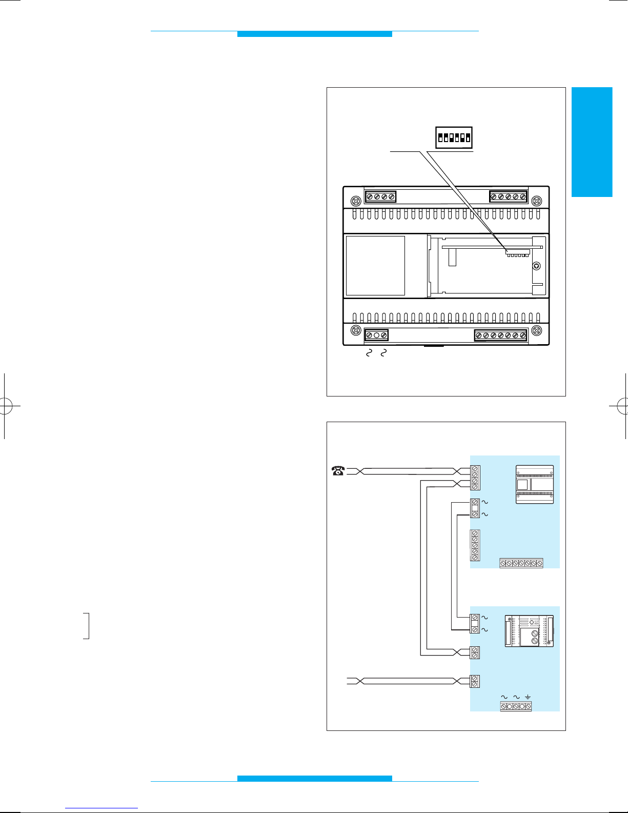
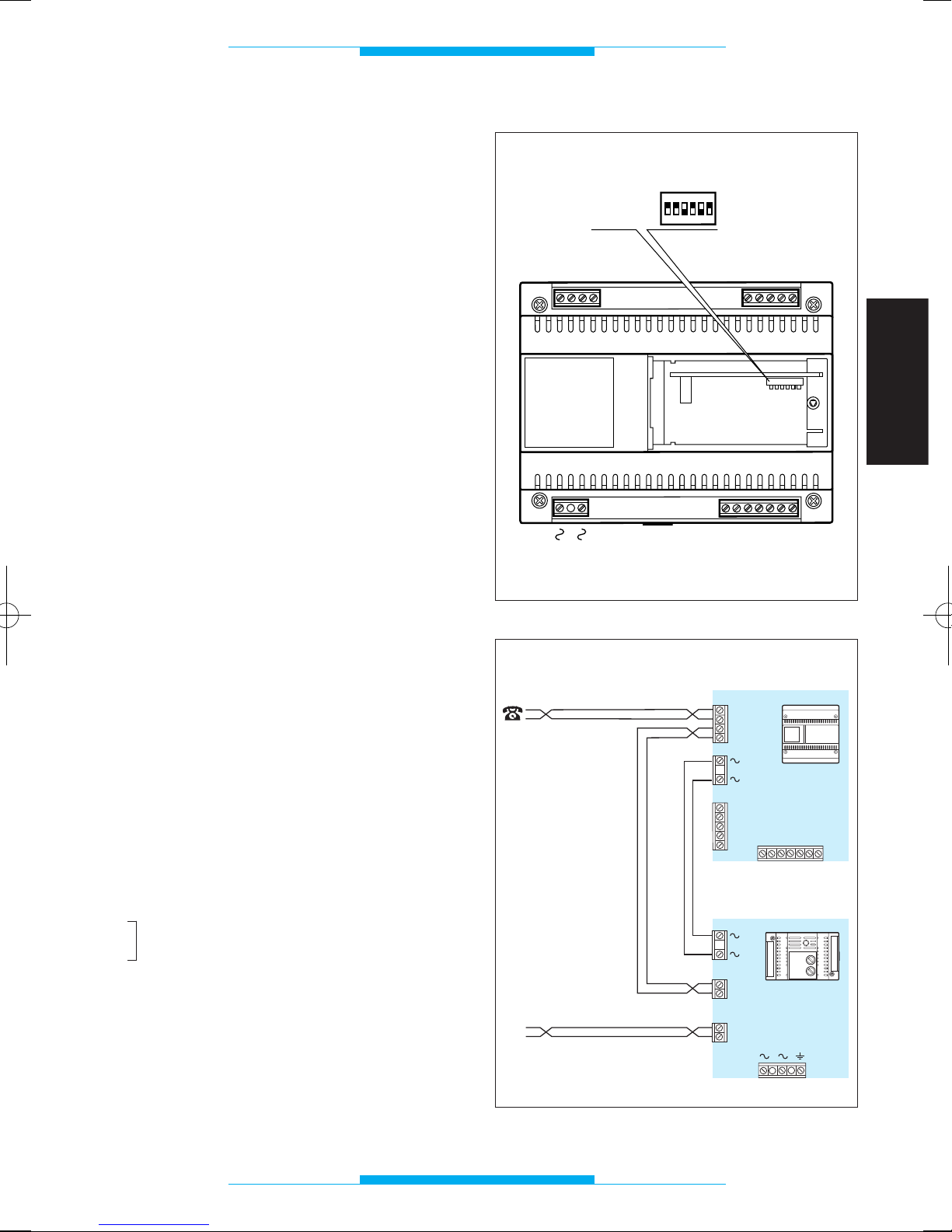
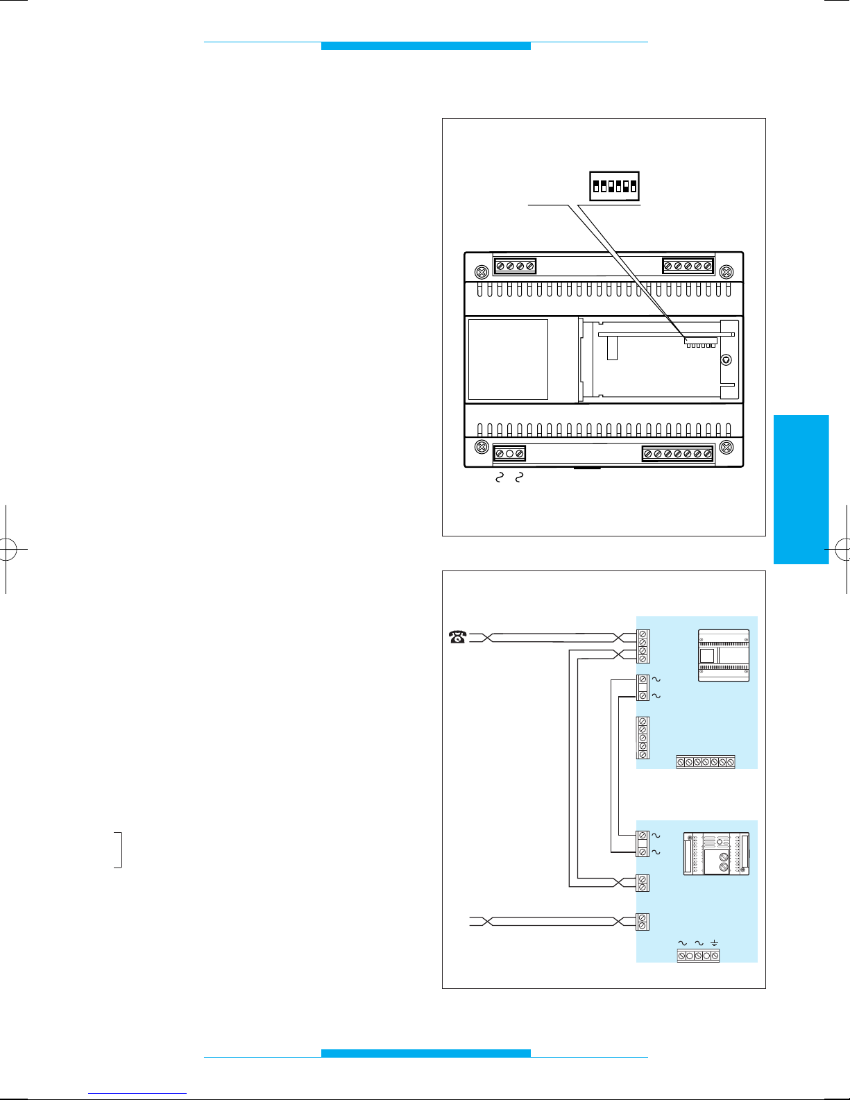
Per accedere alle morsettiere togliere i
coprimorsetti. Si consiglia di utilizzare, per il
collegamento dei telefoni, cavo telefonico
da 6/10.
Distanza massima tra interfaccia telefonica
e telefono: 100 m.
NOTA. L’apparechio va collegato solo su
linee telefoniche analogiche non su linee
digitali ISDN.
Funzione
dei morsetti
Morsettiera T (linea telefonica)
ae linea urbana
be linea urbana
au telefono
bu telefono
Morsettiera C (dall’alimentatore)
5 massa
6 ingresso alimentazione monitor
7 chiamata
8 audio dal posto esterno
9 audio al posto esterno
12 chiamata portineria
22 ausiliario/luce scale
Morsettiera M (al derivato interno)
5 massa
6 uscita alimentazione monitor
7 chiamata
8 audio dal posto esterno
9 audio al posto esterno
Morsettiera A
~
rete
~
ATTENZIONE. SI CONSIGLIA DI PROTEGGERE LA LINEA TELEFONICA E L’ALIMENTAZIONE DI RETE DA SOVRATENSIONI CON IL PROTETTORE DI LINEA
LP/MT.
A
C
5
6
7
8
9
12
T
ae
be
au
bu
M
22
SW1
5
6
7
8
9
ON
OFF
ON
1
2
3
4
56
Fig. 2
Fig. 3
TL
IT/200
T
bu
au
be
ae
A
M
5
6
7
8
9
LP/MT
M3
M4
au
bu
M2
ae
be
56789
C
M1
F2
F1
12 22
Page 10
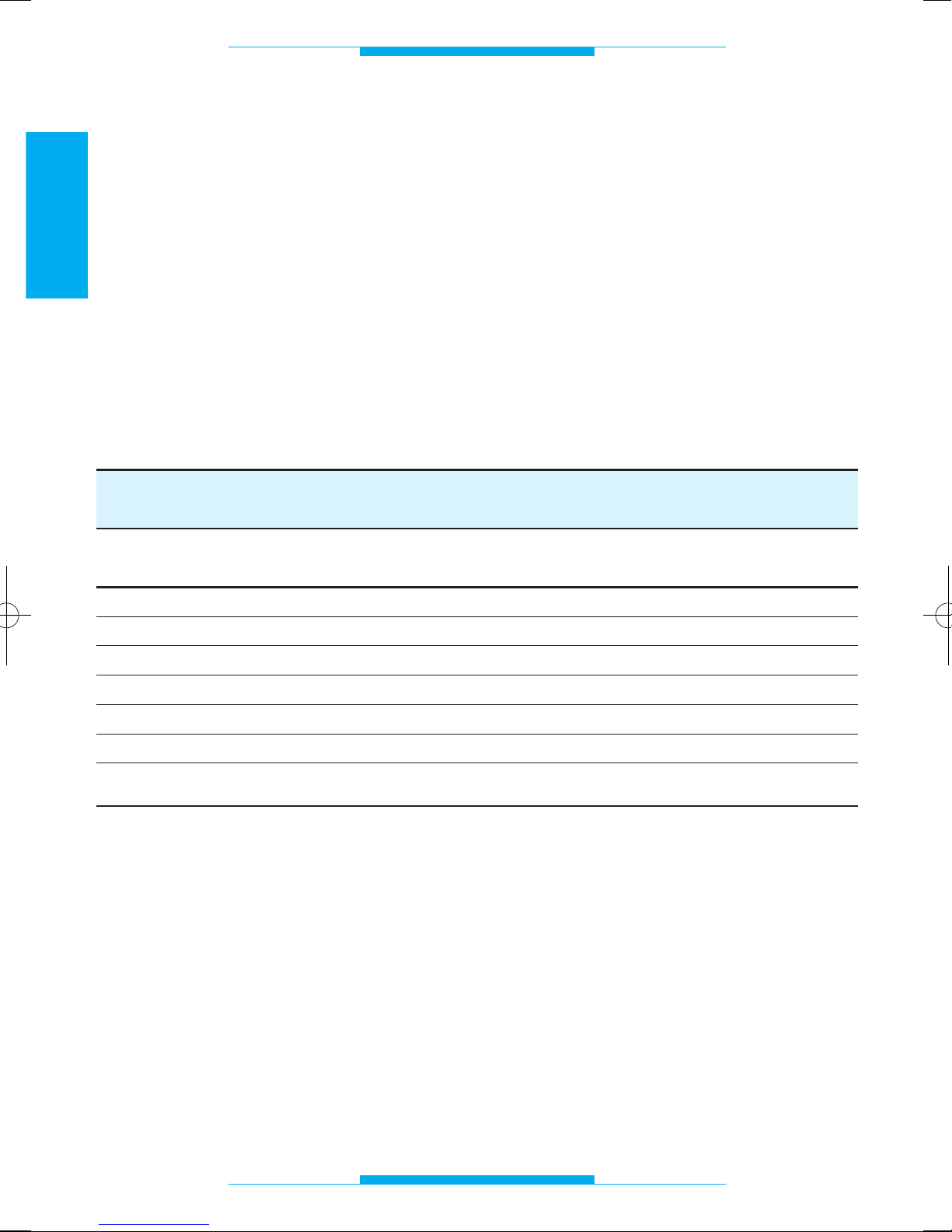
PREDISPOSIZIONE DIP-SWITCH
DIP-SWITCH CITOFONIA VIDEOCITOFONIA VIDEOCITOFONIA
SISTEMA 100 SISTEMA 200
SW1 ON ON ON
SW2 OFF OFF ON
SW3 ON OFF ON
SW4 ON OFF ON
SW5 OFF ON OFF
SW6 ON OFF ON
Il ponticello SW1 viene posizionato in OFF solo durante la procedura di PROGRAMMAZIONE.
8
ITALIANO
MESSA IN FUNZIONE
L’apparecchio permette il collegamento alle
seguenti tipologie d’impianto BPT:
- citofonia convenzionale
- citofonia con segreto di conversazione
- videocitofonia sistema 100
- videocitofonia sistema 200
- chiamata elettronica o codificata
E’ dotato di 6 dip-switch (fig. 2) da posizionare in funzione della tipologia dell’impianto
(fig. 3).
Oltre all’impostazione dei dip-switch, l’ap-
parecchio deve essere anche programmato da telefono per la scelta della tipologia
d’impianto (vedere il capitolo PROGRAMMAZIONE).
L’apparecchio è predisposto per essere
installato in impianti videocitofonici sistema
200.
ATTENZIONE. Per impianti citofonici senza
segreto di conversazione, è necessario programmare l’apparecchio secondo la modalità indicata a pag. 9.
Fig. 3
Page 11
9
ITALIANO
PROGRAMMAZIONE
Configurazione di default
• Modalità riconoscimento flash: omologato.
• Segreto di conversazione: attivo.
• Durata conversazione citofonica: 60 s.
• Durata comando apriporta: 1 s.
• Modalità: impianti con chiamata analogi-
ca.
• Codice programmato per collegamento in
impianti con chiamata codificata: 80155.
• Intercettazione flash: disabilitata.
• Tipo di monitor abbinato al telefono:
XV/200.
Ingresso e uscita dalle
operazioni di programmazione
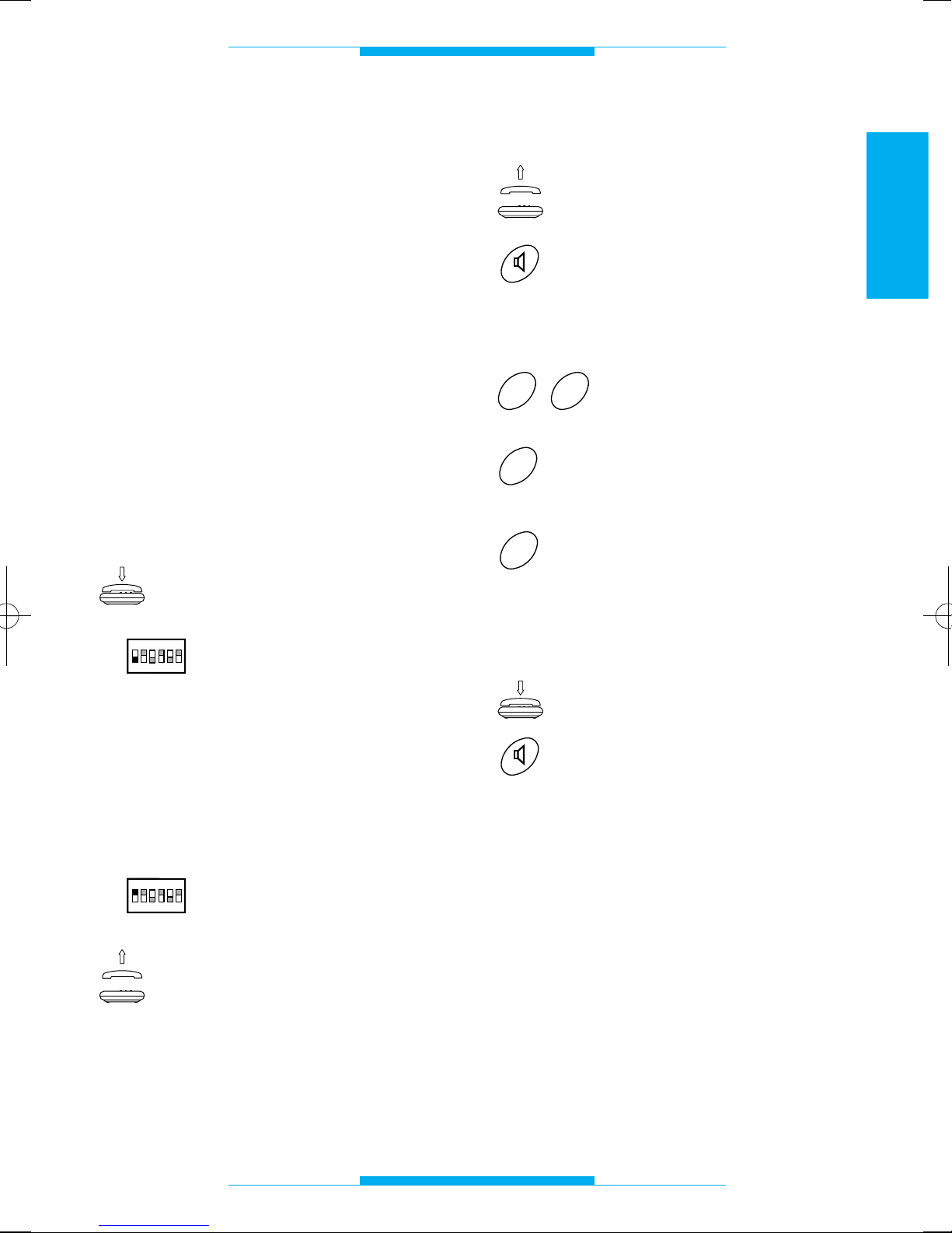
Per entrare in programmazione dal telefono collegato all’interfaccia telefonica:
Assicurarsi che la cornetta
sia agganciata.
Portare il dip-switch 1 in
posizione OFF.
Durante questa fase si possono effettuare
una o più programmazioni consecutive.
L’inserimento dei codici di programmazione
va eseguito durante la pausa del tono di programmazione.
Per uscire dalla fase di programmazione:
Portare il dip-switch 1 in
posizione ON.
Al termine della procedura,
sollevando la cornetta o
premendo il tasto viva-voce,
si deve sentire il tono di libero della linea telefonica.
ON
OFF
ON
1
2
3
4
56
ON
OFF
ON
1
2
3
4
56
Modalità segreto di conversazione
Sollevare la cornetta
oppure
premere il tasto viva-voce.
Dopo questa operazione si deve sentire un
doppio tono di invito alla programmazione.
Digitare 29.
Digitare 0 per modalità
impianto senza segreto
oppure
1 per modalità impianto con
segreto.
Al termine si deve sentire un triplo tono di
conferma.
Riagganciare la cornetta
oppure
premere il tasto viva-voce.
1
0
9
2
Page 12

10
ITALIANO
PROGRAMMAZIONE
Durata conversazione citofonica
Sollevare la cornetta
oppure
premere il tasto viva-voce.
Dopo questa operazione si deve sentire un
doppio tono di invito alla programmazione.
Digitare 27.
Digitare la durata della conversazione (da 10 a 99
secondi), es. 20 per 20
secondi.
Al termine si deve sentire un triplo tono di
conferma.
Riagganciare la cornetta
oppure
premere il tasto viva-voce.
NOTA. Il tempo può essere variato solo per
impianti citofonici senza segreto di conversazione (es. con A/200R).
2
3
4
0
5
6
1
7
8
9
7
2
Modalità analogico o codificato
(vedi istruzioni allegate ai posti esterni digitali)
Sollevare la cornetta
oppure
premere il tasto viva-voce.
Dopo questa operazione si deve sentire un
doppio tono di invito alla programmazione.
Digitare 62.
Digitare 0 per modalità
impianto analogico (
1
)
oppure
1 per modalità impianto
codificato.
Al termine si deve sentire un triplo tono di
conferma.
Riagganciare la cornetta
oppure
premere il tasto viva-voce.
(
1
)
Questa programmazione si rende necessaria solo nel caso si voglia riconfigurare
l’interfaccia precedentemente programmata con codici digitali.
1
0
2
6
Page 13
11
ITALIANO
PROGRAMMAZIONE
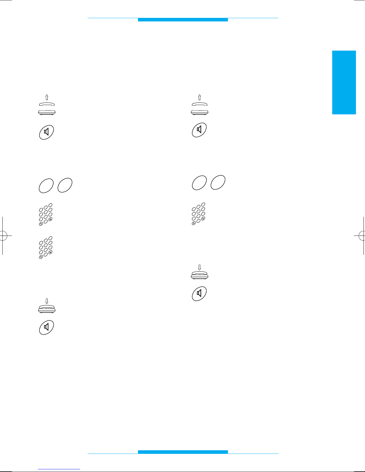
Codice IT/200 in formato
blocco/utente ed impostazione
modo codificato
(vedi istruzioni allegate ai posti esterni digitali)
Sollevare la cornetta
oppure
premere il tasto viva-voce.
Dopo questa operazione si deve sentire un
doppio tono di invito alla programmazione.
Digitare 60.
Digitare il codice di blocco
(da 00 a 80), es. 39.
Digitare il codice utente (da
000 a 161), es. 052.
Al termine si deve sentire un triplo tono di
conferma.
Riagganciare la cornetta
oppure
premere il tasto viva-voce.
2
3
4
0
5
6
1
7
8
9
2
3
4
0
5
6
1
7
8
9
0
6
Codice IT/200 in formato
progressivo ed impostazione
modo codificato
(vedi istruzioni allegate ai posti esterni digitali)
Sollevare la cornetta
oppure
premere il tasto viva-voce.
Dopo questa operazione si deve sentire un
doppio tono di invito alla programmazione.
Digitare 61.
Digitare il codice utente (da
00000 a 13121), es. 01523.
Al termine si deve sentire un triplo tono di
conferma.
Riagganciare la cornetta
oppure
premere il tasto viva-voce.
2
3
4
0
5
6
1
7
8
9
1
6
Page 14
12
ITALIANO
PROGRAMMAZIONE
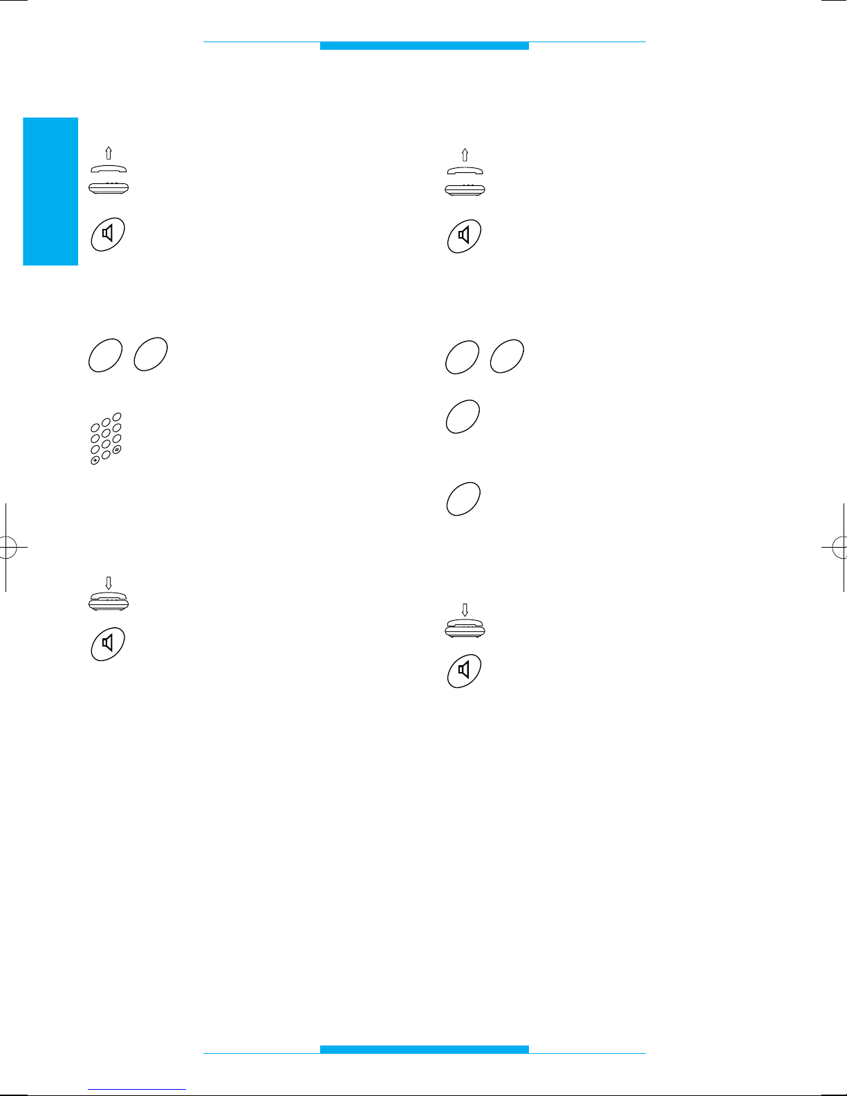
Durata comando apriporta
Sollevare la cornetta
oppure
premere il tasto viva-voce.
Dopo questa operazione si deve sentire un
doppio tono di invito alla programmazione.
Digitare 28.
Digitare la durata del
comando apriporta (da 01 a
15 secondi), es. 06 per 6
secondi.
Al termine si deve sentire un triplo tono di
conferma.
Riagganciare la cornetta
oppure
premere il tasto viva-voce.
NOTA. È possibile sfruttare questa funzione
solo con alimentatori privi di timer centralizzati (es. A/200R o VA/100.
01
impostato per
comando elettroserratura manuale).
2
3
4
0
5
6
1
7
8
9
8
2
Modalità riconoscimento flash
Sollevare la cornetta
oppure
premere il tasto viva-voce.
Dopo questa operazione si deve sentire un
doppio tono di invito alla programmazione.
Digitare 20.
Digitare 0 per riconoscimento flash omologato
oppure
1 per riconoscimento flash
lungo.
Al termine si deve sentire un triplo tono di
conferma.
Riagganciare la cornetta
oppure
premere il tasto viva-voce.
1
0
0
2
Page 15
13
ITALIANO
PROGRAMMAZIONE
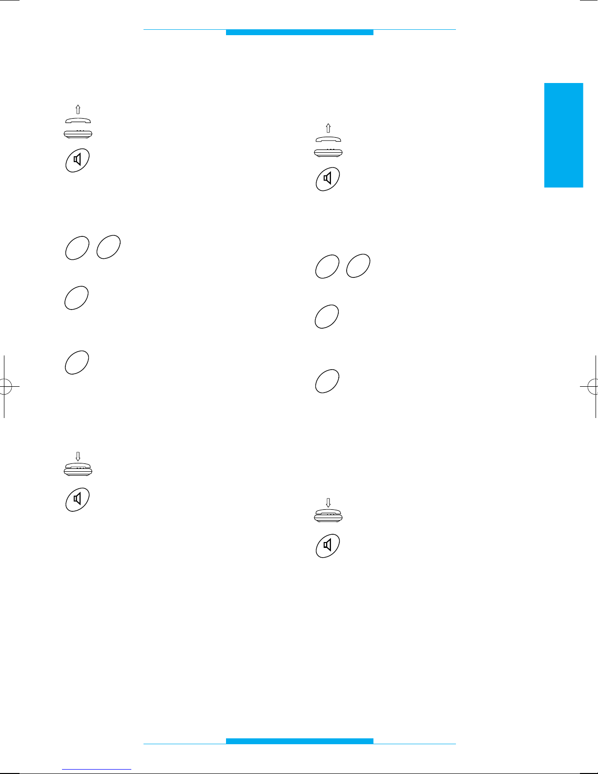
Intercettazione flash
Sollevare la cornetta
oppure
premere il tasto viva-voce.
Dopo questa operazione si deve sentire un
doppio tono di invito alla programmazione.
Digitare 63.
Digitare 0 per intercettazione flash disabilitata (collegamento al telefono XT/200)
oppure
1 per intercettazione flash
abilitata (collegamento al
telefono DTMF generico).
Al termine si deve sentire un triplo tono di
conferma.
Riagganciare la cornetta
oppure
premere il tasto viva-voce.
1
0
3
6
Tipo di monitor
da abbinare al telefono
Sollevare la cornetta
oppure
premere il tasto viva-voce.
Dopo questa operazione si deve sentire un
doppio tono di invito alla programmazione.
Digitare 64.
Digitare 0 quando viene utilizzato il monitor XV/200 o
XVC/200
oppure
1 quando viene utilizzato il
monitor IMT/200 o IMTC/200.
NOTA. In impianti con derivati interni misti
digitare 1.
Al termine si deve sentire un triplo tono di
conferma.
Riagganciare la cornetta
oppure
premere il tasto viva-voce.
1
0
4
6
Page 16
14
ITALIANO
PROGRAMMAZIONE
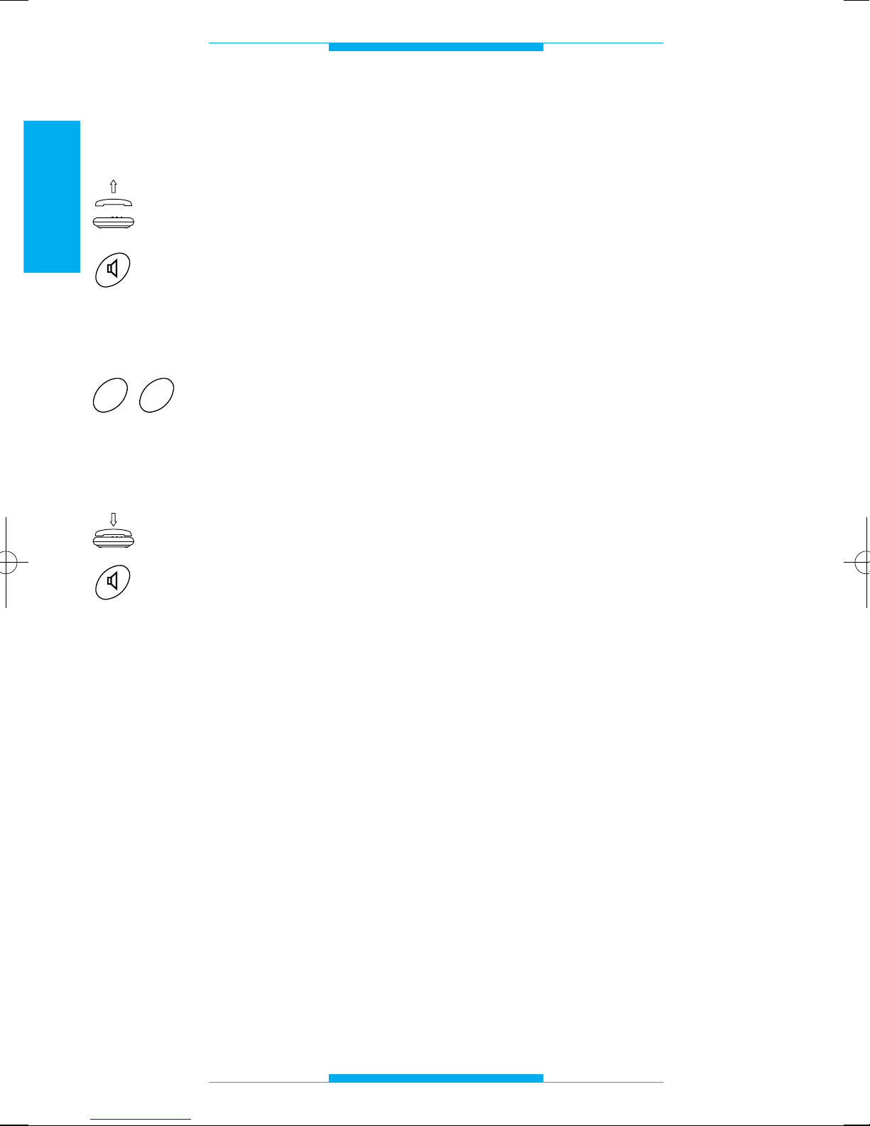
Ripristino della
configurazione di default
Sollevare la cornetta
oppure
premere il tasto viva-voce.
Dopo questa operazione si deve sentire un
doppio tono di invito alla programmazione.
Digitare 00.
Al termine si deve sentire un triplo tono di
conferma.
Riagganciare la cornetta
oppure
premere il tasto viva-voce.
0
0
Page 17
15
ITALIANO
CARATTERISTICHE TECNICHE
• Alimentazione: 230 V ca - 50 Hz.
• Assorbimento: 6 VA max.
• Tensione di uscita: 24 V.
• Tensione di chiamata 50 V eff./50 Hz.
• Lunghezza max. dei cavi di connessione
per ciascun interno: 100 m (cavo telefonico da 6/10).
• Quantità di derivati sulla stessa linea: 5
max.
• Protezione elettronica ripristinabile.
• Deviazione di frequenza: secondo le
norme CCITT.
• Abilitazione monitor per la durata della
conversazione.
• Durata massima conversazione citofoni-
ca: 99 s.
• Collegamento per luce scale singolo
(tipo OPEN COLLECTOR 24 Vcc, 50 mA).
• Collegamento per chiamata portiere.
• Durata tempo di flash (R) programmabile.
• Durata tempo d’innesco apriporta da 1 a
15 s.
• Collegamento linea urbana anche in man-
canza di alimentazione.
• Temperatura di funzionamento: da 0 °C a
+35 °C.
• Umidità relativa: 90% senza condensa.
• Classe d’isolamento II.
• Dimensioni: modulo da 8 unità basso per
guida DIN.
• Frequenza toni di segnalazione: 375 Hz.
L’apparecchio è omologato secondo le
norme CTR 21 e soddisfa la norma EN
60950, relativa alla sicurezza elettrica, e la
direttiva 89/336/EEC modificata con
93/68/EEC, relative alla compatibilità elettromagnetica.
Approvazione europea rilasciata dal
BZT-ETS CERTIFICATION GmbH
Page 18
16
ITALIANO
FUNZIONE
TEMPO (secondi)
1234
5
60
FUNZIONE
TEMPO (secondi)
1
2
3
4
50
Programmazione
Conferma di fine programmazione
Attesa
Avviso
Citofonica
Urbana
6
= Pausa= Nota
= Pausa= Nota
TONI E RITMI
Toni di segnalazione
Ritmi di chiamata
Page 19
GLOSSARIO
Citofono
Permette di comunicare con il posto esterno
e di comandare l’apertura della porta.
Default
Con questo termine viene definita ogni predisposizione o programmazione eseguita
dal fabbricante.
Flash (R)
Premendo questo tasto dal telefono collegato si predispone l’interfaccia a ricevere
un comando (e non un numero telefonico)
dalla tastiera.
Linea urbana
Collegamento che permette di comunicare
con gli utenti dell’elenco telefonico.
Posto esterno
Permette al visitatore di effettuare la chiamata all’utente e di conversare.
Se è dotato di telecamera, trasmette le
immagini al videocitofono in casa.
Telefono
Apparecchio che normalmente permette di
fare e ricevere telefonate sulla linea urbana;
con il centralino IT/200 il telefono può essere usato anche come citofono.
Telefono decadico
Telefono con disco combinatore; anche
alcuni telefoni a tastiera sono decadici: il
telefono è decadico se, componendo un
numero, alla cornetta si odono degli scatti.
Telefono multifrequenza
Chiamato anche MF o DTMF, è il telefono
più moderno.
Un telefono è multifrequenza se, componendo un numero, alla cornetta si odono dei
toni.
Videocitofono
Oltre alle normali funzioni del citofono, permette di vedere sullo schermo il visitatore
che chiama dal posto esterno.
17
ITALIANO
Page 20
18
ITALIANO
FUNZIONI
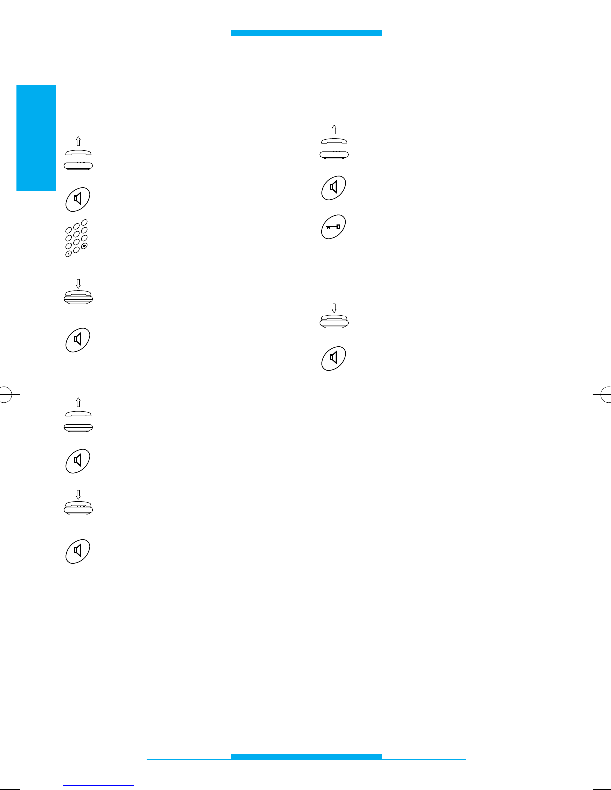
Chiamata su linea urbana
È possibile inoltrare le chiamate nel modo
abituale, come con ogni altro apparecchio.
Sollevare la cornetta
oppure
premere il tasto viva-voce.
Comporre sulla tastiera il numero desiderato.
A fine conversazione riagganciare la cornetta
oppure
premere il tasto viva-voce.
Risposta alle chiamate in arrivo
Sollevare la cornetta
oppure
premere il tasto viva-voce.
A fine conversazione riagganciare la cornetta
oppure
premere il tasto viva-voce.
Il telefono squilla con ritmi diversi a seconda che la chiamata provenga da una linea
urbana o dal posto esterno.
Vedere il capitolo TONI E RITMI della suoneria.
2
3
4
0
5
6
1
7
8
9
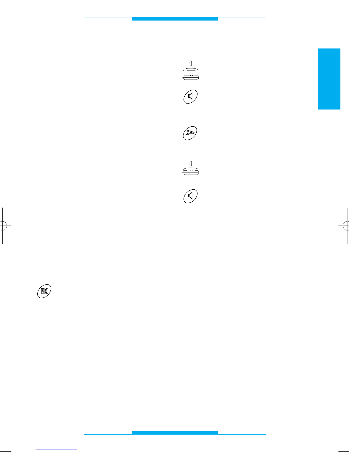
Risposta a chiamata da posto
esterno ed apertura della porta
Sollevare il microtelefono
oppure
premere il tasto viva-voce.
Se si desidera far entrare il chiamante premere il tasto apriporta
(per telefoni bpt, per altri telefo-
ni consultare la tabella riassuntiva).
Riagganciare la cornetta
oppure
premere il tasto viva-voce.
NOTA. Se l’interfaccia è programmata con
la funzione INTERCETTAZIONE FLASH
disabilitata, non è possibile da un telefono
standard multifrequenza, eseguire il comando quando si è in comunicazione con la
linea urbana.
Page 21
19
ITALIANO
FUNZIONI
Autoinserimento su posto esterno
È possibile attivare il posto esterno per una
qualsiasi delle seguenti esigenze:
• sorvegliare l’esterno con audio e video
(se il posto esterno è dotato di telecamera);
• scambiare i posti esterni;
• attivare l’apriporta.
NOTA. L’autoinserimento è possibile solo
con l’abbinamento del modulo video XV/200
e ad impianto videocitofonico libero.
Cambio interlocutore
Questo servizio consente all’utente, in
comunicazione con una linea esterna o
posto esterno, di rispondere ad una chiamata proveniente dall’altra linea mettendo
in attesa la comunicazione in corso.
L’interlocutore non in conversazione viene
informato di questa condizione mediante
tono acustico.
NOTA. Durante la conversazione l’utente
viene informato della chiamata in arrivo con
avviso acustico.
Per cambiare interlocutore durante una conversazione:
Premere il tasto di commutazione
citofono/telefono (per telefoni bpt,
per altri telefoni consultare la
tabella riassuntiva).
NOTA. Se l’interfaccia è programmata con
la funzione INTERCETTAZIONE FLASH
disabilitata, non è possibile da un telefono
standard multifrequenza, eseguire il comando quando si è in comunicazione con la
linea urbana.
Chiamata portiere
Sollevare la cornetta
oppure
premere il tasto viva-voce.
Attendere il tono di invito alla selezione.
Premere il tasto di chiamata portiere (per telefoni bpt, per altri
telefoni consultare la tabella
riassuntiva).
A fine conversazione riagganciare la cornetta
oppure
premere il tasto viva-voce.
NOTA. Se l’interfaccia è programmata con
la funzione INTERCETTAZIONE FLASH
disabilitata, non è possibile da un telefono
standard multifrequenza, eseguire il comando quando si è in comunicazione con la
linea urbana.
Page 22
20
ITALIANO
FUNZIONI
Comando
ausiliario/luce scale da telefono
Sollevare la cornetta
oppure
premere il tasto viva-voce.
Attendere il tono di invito alla selezione.
Premere il tasto ausiliario (per
telefoni bpt, per altri telefoni
consultare la tabella riassuntiva).
Riagganciare la cornetta
oppure
premere il tasto viva-voce.
NOTA. Se l’interfaccia è programmata con
la funzione INTERCETTAZIONE FLASH
disabilitata, non è possibile da un telefono
DTMF, eseguire il comando quando si è in
comunicazione con la linea urbana.
AVVERTENZA. In impianti con segreto di
conversazione questo comando è disponibile solo se il derivato interno è stato chiamato dal posto esterno.
Disabilitazione avviso acustico
di chiamata in arrivo
Digitare R83 prima di
comporre il numero
telefonico.
Per tutto il tempo della conversazione il
tono di avviso viene disabilitato.
Utilizzare questa funzione quando viene
effettuato il collegamento con un modem.
Se si vuole ottenere in automatico la disabilitazione, aggiungere la serie di caratteri
!83, (vedere le istruzioni del software della
connessione telefonica).
Accesso ai servizi in DTMF
della compagnia telefonica
L’accesso è possibile sempre quando si è
configurata l’interfaccia come INTERCETTAZIONE FLASH disabilitata, mentre è possibile solo in comunicazione con la linea
urbana e in assenza di chiamate dal posto
esterno citofonico, quando è configurata
come INTERCETTAZIONE FLASH abilitata.
3
8
R
Page 23
21
ITALIANO
FUNZIONI
TELEFONO BPT TELEFONO TELEFONO
XT/200 MULTIFREQUENZA DECADICO
PROGRAMMAZIONE si si non possibile
CHIAMATA URBANA diretto diretto diretto
RICEZIONE CHIAMATE si si si
URBANE/TELEFONICHE
ACCESSO AI SERVIZI si si non possibile
TELECOM IN DTMF
AUTOINSERIMENTO (XV/200) R+86 non possibile
APRIPORTA R+85 non possibile
AUSILIARIO/LUCE SCALE R+88 non possibile
CENTRALIZZATO (uscita
disponibile nell’alimentatore)
AUSILIARIO/LUCE SCALE R+88 non possibile
SINGOLO (uscita
disponibile nell’ IT/200) (
1
)
CHIAMATA PORTIERE R+87 non possibile
CAMBIO INTERLOCUTORE R+80 non possibile
(1) E’ possibile utilizzare l’uscita AUSILIARIO/LUCE SCALE SINGOLO anche in impianti con
LUCE SCALE CENTRALIZZATO impostando i dip-switch n° 4 e 5 in OFF.
Funzioni ottenibili con l’utilizzo del telefono bpt
e con telefoni standard
Page 24
22
ITALIANO
Page 25
CONTENTS
23
ENGLISH
Instructions for the installer
Foreword . . . . . . . . . . . . . . . . . . . . . . . . .24
Warnings . . . . . . . . . . . . . . . . . . . . . . . . .25
Installation . . . . . . . . . . . . . . . . . . . . . . . .26
Connections . . . . . . . . . . . . . . . . . . . . . .27
Prior to operation . . . . . . . . . . . . . . . . . .28
Programming . . . . . . . . . . . . . . . . . . . . . .29
- Default settings . . . . . . . . . . . . . . . . . .29
- Entering and exiting the
programming functions . . . . . . . . . . . .29
- Conversation privacy mode . . . . . . . . .29
- Entry panel conversation length . . . . .30
- Analogue or coded mode . . . . . . . . . .30
- IT/200 code in block/user format
and coded mode setup . . . . . . . . . . . .31
- IT/200 code in progressive format
and coded mode setup . . . . . . . . . . . .31
- Door lock release triggering time . . . .32
- Flash detection mode . . . . . . . . . . . . .32
- Flash interception . . . . . . . . . . . . . . . . .33
- Type of monitor to be combined
with the telephone . . . . . . . . . . . . . . . .33
- Resetting default settings . . . . . . . . . .34
Technical features . . . . . . . . . . . . . . . . . .35
Tones and frequencies . . . . . . . . . . . . . .36
- Signal tones . . . . . . . . . . . . . . . . . . . . .36
- Call frequencies . . . . . . . . . . . . . . . . . .36
Instructions for the user
Glossary . . . . . . . . . . . . . . . . . . . . . . . . .37
Functions . . . . . . . . . . . . . . . . . . . . . . . . .38
- Call on local line . . . . . . . . . . . . . . . . . .38
- Answering incoming calls . . . . . . . . . .38
- Answering calls from entry
panel and opening the door . . . . . . . .38
- Self-connection on entry panel . . . . . .39
- Interlocutor switching . . . . . . . . . . . . . .39
- Porter call . . . . . . . . . . . . . . . . . . . . . . .39
- Telephone auxiliary/stair
light control . . . . . . . . . . . . . . . . . . . . . .40
- Disabling the incoming
call warning tone . . . . . . . . . . . . . . . . .40
- Accessing in DTMF services
of telephone company . . . . . . . . . . . . .40
- Functions available using
the bpt telephone and
standard telephone sets . . . . . . . . . . .41
Page 26
FOREWORD
24
ENGLISH
The telephone interface enables a telephone set to be connected to the 200 series
and 100 series video entry and audio entry
control lines, whether coded or not.
In addition, apart from the bpt telephone, it
enables ordinary decadic or DTMF sets,
cordless phones, answering machines,
modems, PABX switchboards etc. to be
used.
The unit also enables calls to be sent to an
analogue or digital porter switchboard and
to control the door lock release, centralized
stair light functions, etc.
The unit, housed in a 8 DIN module receptacle, is made up of a main printed circuit
and a board containing the dip-switches for
programming and selecting the system
type.
Basic functions
• Direct access to the local telephone line.
• Connection to the series 200 video entry
control system with self-connection function (where combined with the monitor
module).
• Connection to the 100 series video entry
control system.
• Connection to the audio entry control
system with or without conversation privacy.
• Conversation privacy for BPT installa-
tions.
• Integrated coded interface.
• Telephone communication even during
power outages.
• Different call tone for entry panel/telepho-
ne calls.
• Door lock release control.
• Auxiliary/stair light control.
• Porter call.
• Hold (telephone/entry panel call).
• Telephone line protection.
• Programming of the unit using telephone
set.
• Mains power supply.
Page 27
WARNINGS
25
ENGLISH
Read the warnings contained herein carefully as they provide important instructions for
safe operation, installation and maintenance.
Having removed the packaging, make sure
the unit is intact.
The packaging materials (plastic bags,
foam polystyrene, etc.) must be kept out of
the reach of children as they represent
potential sources of danger.
The material must be disposed of according
to the laws in force.
The installation of the system must comply
with the safety rules in force.
Do not run telephone cables in the same
raceways as electrical cables.
Install the unit in a fairly dust-free room,
away from units liable to generate high-frequency electrical noise such as welding
machines, electric motors, microwave
ovens, air conditioners, etc.
It is advisable to install a suitable cutout and
safety device upstream of the power supplier.
Before connecting up the unit, make sure
the data on the rating plate correspond to
the mains power supply.
This unit must be used only for the use for
which it was explicitly designed; any other
use shall be considered improper and
hazardous.
The manufacturer cannot be held responsible for any damage as a result of improper,
incorrect and unreasonable use.
Before cleaning or doing any maintenance
work on the unit, disconnect it from the
mains power supply by opening the
system’s switch.
In the event the unit is faulty and/or operates poorly, disconnect it from the power
supply and do not tamper with it.
When in need of repair work, contact only
technical servicing centres authorized by
the manufacturer.
Failure to comply with the above provisions
may compromise the safety of the unit.
The installer must make sure that the user
information, where applicable, is to be
found on the unit.
All the equipment making up the system
must be used only for the user for which
they were designed.
Page 28
INSTALLATION
26
ENGLISH
The unit, housed in a low profile module of 8
DIN units, can be installed without terminal
covers in cabinets featuring DIN guides (EN
50022).
See fig. 1A for the overall dimensions.
Alternatively, it can be wall mounted, using
the DIN guide supplied, and in this case will
require terminal covers.
See fig. 1B for the overall dimensions.
43,5
45
7,5
57
140
106
A
B
64,5
140
145
Fig. 1
Page 29
CONNECTIONS
27
ENGLISH
In order to access the terminals, remove the
terminal covers. The use of a 6/10 telephone cable is recommended for connecting
the telephones.
The maximum distance between the
telephone interface and the telephone is
100 m.
NOTE. The unit must be connected on analogue telephone lines only and not digital
ISDN lines.
Functions of each terminal
Terminal block T (telephone line)
ae local line
be local line
au telephone
bu telephone
Terminal block C (from power supplier)
5 earth
6 monitor power supply input
7 call
8 audio from entry panel
9 audio to entry panel
12 porter call
22 auxiliary/stair light
Terminal block M (to receiver)
5 earth
6 monitor power supply output
7 call
8 audio from entry panel
9 audio to entry panel
Terminal block A
~
mains
~
MPORTANT. WE RECOMMEND PROTECTING YOUR TELEPHONE LINE AND
MAINS POWER SUPPLY FROM OVERLOADS WITH THE LP/MT LINE PROTECTOR.
A
C
5
6
7
8
9
12
T
ae
be
au
bu
M
22
SW1
5
6
7
8
9
ON
OFF
ON
1
2
3
4
56
Fig. 2
Fig. 3
TL
IT/200
T
bu
au
be
ae
A
M
5
6
7
8
9
LP/MT
M3
M4
au
bu
M2
ae
be
56789
C
M1
F2
F1
12 22
Page 30
DIP-SWITCH SETTINGS
DIP-SWITCH AUDIO SYSTEM VIDEO VIDEO
SYSTEM 100 SYSTEM 200
SW1 ON ON ON
SW2 OFF OFF ON
SW3 ON OFF ON
SW4 ON OFF ON
SW5 OFF ON OFF
SW6 ON OFF ON
The jumper SW1 is only set to OFF during the PROGRAMMING procedure.
28
ENGLISH
PRIOR TO OPERATION
The unit enables connections to the following BPT system types:
- conventional audio entry control system
- audio entry control system with conversation privacy
- system 100 video entry control system
- system 200 video entry control system
- electronic or coded call
It features 6 dip-switches (fig. 2) whose settings depend on the type of system (fig. 3).
Apart from the setting of the dip-switches,
the unit must also be programmed using
the telephone to set the system type (see
section entitled PROGRAMMING).
The unit is designed to be installed in
system 200 video entry control systems.
IMPORTANT INSTALLER NOTE. When
setting up for audio system 200, in addition
to setting the dip-switches as shown above,
carry out the programming shown overleaf
for Conversation Privacy and set for 0 mode
(see page 29).
Fig. 3
Page 31
PROGRAMMING
29
ENGLISH
Default settings
• Flash detection mode: type approved.
• Conversation privacy: on.
• Conversation length: 60 s.
• Door lock release triggering time: 1 s.
• Mode: systems with analogue call.
• Programmed code for connection in
systems with coded call: 80155.
• Flash interception: disabled.
• Type of monitor combined with the
telephone: XV/200.
Entering and exiting the
programming functions
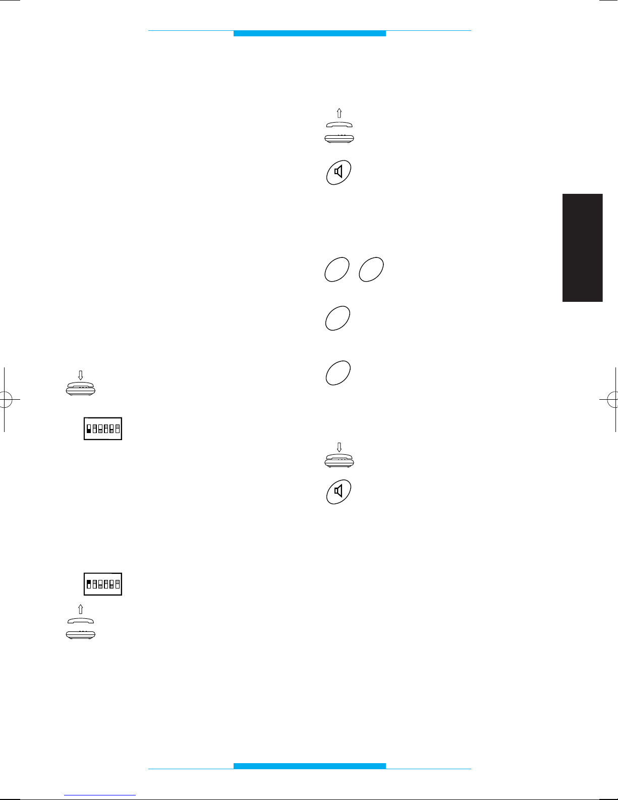
In order to enter programming mode via
the telephone connected to the telephone interface:
Make sure the receiver is
hung up.
Set dip-switch 1 to OFF.
During this phase, one or more programming procedures can be carried out in a
row.
The programming codes must be entered
during the pause in the programming tone.
In order to exit programming mode:
Set dip-switch 1 to ON.
Once finished, when the
receiver is lifted or handsfree button pressed, the
dial tone must be heard.
ON
OFF
ON
1
2
3
4
56
ON
OFF
ON
1
2
3
4
56
Conversation privacy mode
Lift the receiver
or
press the hands-free key.
Following this operation, a double tone
should sound, prompting you to commence
programming.
Key in 29.
Press 0 for the no-privacy
mode
or
1 for the privacy mode.
Once finished, you should hear a triple tone
confirming the setting.
Replace the receiver
or
press the hands-free key.
1
0
9
2
Page 32
PROGRAMMING
30
ENGLISH
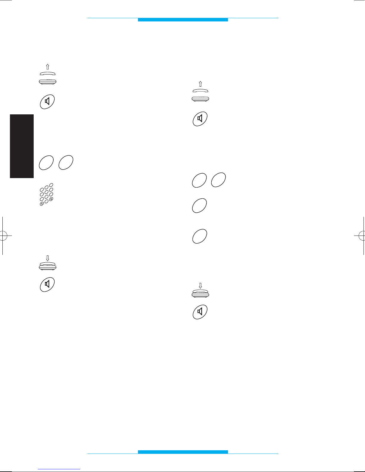
Entry panel conversation length
Lift the receiver
or
press the hands-free key.
Following this operation, a double tone
should sound, prompting you to commence
programming.
Key in 27.
Key in conversation length
(in the range 10 to 99
seconds), e.g. 20 for 20
seconds.
Once finished, you should hear a triple tone
confirming the setting.
Replace the receiver
or
press the hands-free key.
NOTE. The time can only be varied for
audio entry control systems without conversation privacy (e.g. with A/200R).
2
3
4
0
5
6
1
7
8
9
7
2
Analogue or coded mode
(see instructions attached to the digital entry
panels)
Lift the receiver
or
press the hands-free key.
Following this operation, a double tone
should sound, prompting you to commence
programming.
Key in 62.
Press 0 for analogue mode
(
1
)
or
1 for coded mode.
Once finished, you should hear a triple tone
confirming the setting.
Replace the receiver
or
press the hands-free key.
(
1
)
This programming procedure is only
necessary in the event you wish to reconfigure the interface previously programmed
with digital codes.
1
0
2
6
Page 33
PROGRAMMING
31
ENGLISH
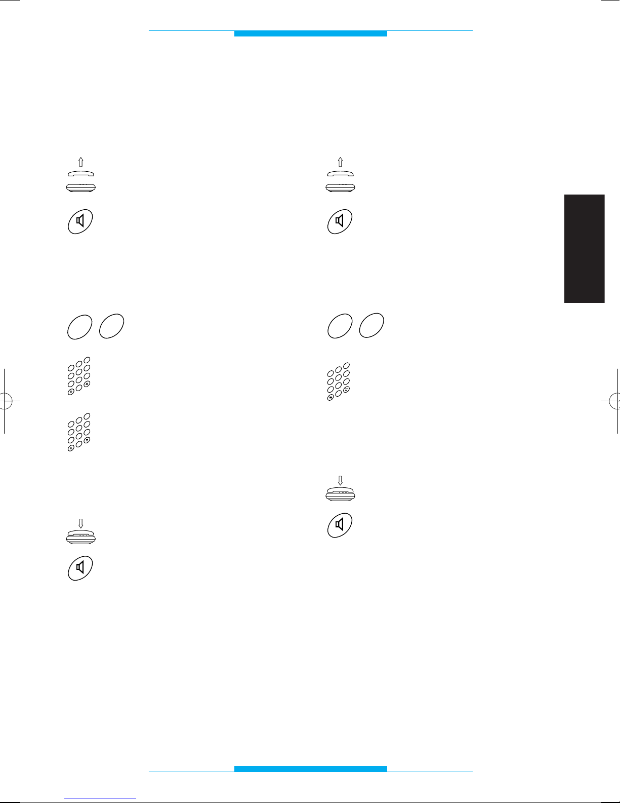
IT/200 code in block/user
format and coded mode setup
(see instructions attached to the digital entry
panels)
Lift the receiver
or
press the hands-free key.
Following this operation, a double tone
should sound, prompting you to commence
programming.
Key in 60.
Key in the block code (in
the range 00 to 80), e.g. 39.
Key in the user code (in the
range 000 to 161), e.g. 052.
Once finished, you should hear a triple tone
confirming the setting.
Replace the receiver
or
press the hands-free key.
2
3
4
0
5
6
1
7
8
9
2
3
4
0
5
6
1
7
8
9
0
6
IT/200 code in progressive
format and coded mode setup
(see instructions attached to the digital entry
panels)
Lift the receiver
or
press the hands-free key.
Following this operation, a double tone
should sound, prompting you to commence
programming.
Key in 61.
Key in the user code (in the
range 00000 to 13121), e.g.
01523.
Once finished, you should hear a triple tone
confirming the setting.
Replace the receiver
or
press the hands-free key.
2
3
4
0
5
6
1
7
8
9
1
6
Page 34
PROGRAMMING
32
ENGLISH
Door lock release triggering
time
Lift the receiver
or
press the hands-free key.
Following this operation, a double tone
should sound, prompting you to commence
programming.
Key in 28.
Key in the door lock release
triggering time (in the range
01 to 15 seconds), e.g. 06
for 6 seconds.
Once finished, you should hear a triple tone
confirming the setting.
Replace the receiver
or
press the hands-free key.
NOTE. This function can only be used with
power suppliers with no centralized timers
(e.g. A/200R or VA/100.
01
set for manual
solenoid lock release control).
2
3
4
0
5
6
1
7
8
9
8
2
Flash detection mode
Lift the receiver
or
press the hands-free key.
Following this operation, a double tone
should sound, prompting you to commence
programming.
Key in 20.
Press 0 for type approved
flash detection
or
1 for long flash detection.
Once finished, you should hear a triple tone
confirming the setting.
Replace the receiver
or
press the hands-free key.
1
0
0
2
Page 35
PROGRAMMING
33
ENGLISH
Flash interception
Lift the receiver
or
press the hands-free key.
Following this operation, a double tone
should sound, prompting you to commence
programming.
Key in 63.
Press 0 to disable flash
interception (connection to
XT/200 telephone)
or
1 to enable flash intercep-
tion (connection to generic
DTMF telephone).
Once finished, you should hear a triple tone
confirming the setting.
Replace the receiver
or
press the hands-free key.
1
0
3
6
Type of monitor to be combined
with the telephone
Lift the receiver
or
press the hands-free key.
Following this operation, a double tone
should sound, prompting you to commence
programming.
Key in 64.
Press 0 when using XV/200
or XVC/200 monitor
or
1 when using IMT/200 or
IMTC/200 monitor.
NOTE. In systems with mixed extensions,
press 1.
Once finished, you should hear a triple tone
confirming the setting.
Replace the receiver
or
press the hands-free key.
1
0
4
6
Page 36
PROGRAMMING
34
ENGLISH
Resetting default settings
Lift the receiver
or
press the hands-free key.
Following this operation, a double tone
should sound, prompting you to commence
programming.
Key in 00.
Once finished, you should hear a triple tone
confirming the setting.
Replace the receiver
or
press the hands-free key.
0
0
Page 37
TECHNICAL FEATURES
35
ENGLISH
• Supply voltage: 230 V AC 50 Hz.
• Current demand: 6 VA max.
• Voltage output: 24 V.
• Call voltage active 50 V/50 Hz.
• Max. length of connecting cables for
each extension: 100 m (6/10 telephone
cable).
• Amount of extensions on the same line: 5
max.
• Reprimable electronic safety device.
• Frequency deviation: according to CCITT
standards.
• Monitor enabling for the duration of the
conversation.
• Maximum entry panel conversation
length: 99 s.
• Connection for single stair light (OPEN
COLLECTOR type 24 V DC, 50 mA).
• Connection for porter call.
• Programmable flash (R) length.
• Door lock release triggering time in the
range 1 to 15 s.
• Local line connection even during power
outages.
• Working temperature range: from 0 °C to
+35 °C.
• Relative humidity: 90% with no condensa-
tion.
• Insulation rating: II.
• Dimensions: 8 DIN units module.
• Signal tone frequency: 375 Hz.
The unit is type approved according to standard CTR 21 and meets the requirements of
the EN 60950 standard relating to electrical
safety, and of the 89/336/EEC directive
amended with 93/68/EEC directive relating
to electromagnetic compatibility.
European approval issued by
BZT-ETS CERTIFICATION GmbH
Page 38
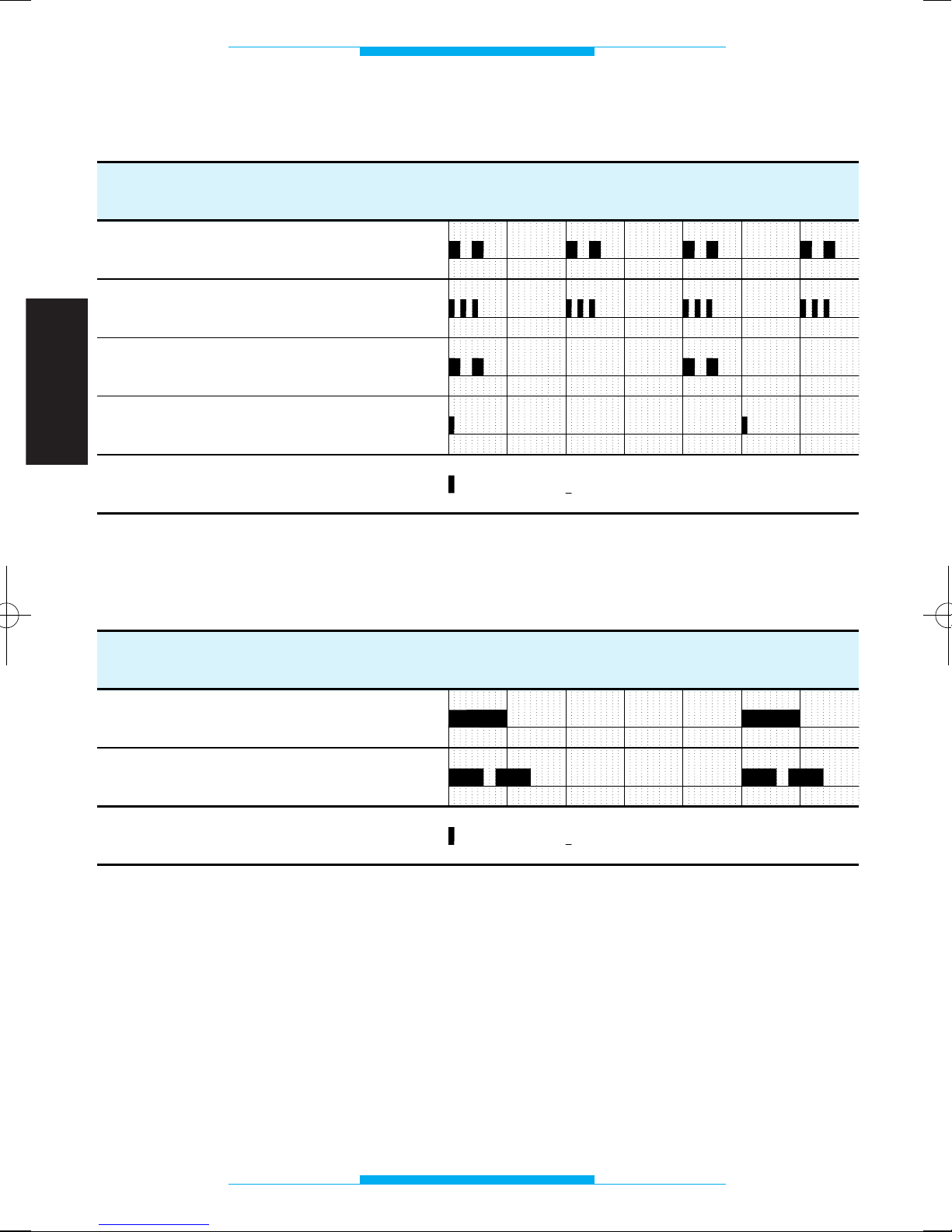
TONES AND FREQUENCIES
36
ENGLISH
Function
TIME (seconds)
1234
5
60
FUNCTION
TIME (seconds)
1
2
3
4
50
Programming
End-of-programming confirmation
Wait
Warning
Entry panel call
Telephone call
6
= Pause= Note
= Pause= Note
Signal tones
Call frequencies
Page 39
GLOSSARY
37
ENGLISH
Handset
Enables the user to talk with the entry panel
and release the door lock.
Default
This term is used to define any settings or
programming performed by the manufacturer.
Flash (R)
When this button on the connected telephone is pressed, the interface stands by to
receive a command (and not a telephone
number) via the push-buttons.
Local line
Connection which enables communication
with the other users on the telephone
network.
Entry panel
Enables the visitor to call the occupant and
talk with him/her.
Where it features a camera, the images are
sent to the video entry handset in the home.
Telephone
Unit which normally enables telephone calls
to be made and received on the local line;
with the IT/200 switchboard, the telephone
can also be used as an audio entry handset.
Decadic telephone
A telephone with a dial, through some pushbutton phones are also decadic: the
telephone is decadic if you hear clicks in
the receiver whilst the number is being dialled.
Multifrequency telephone
Also known as MF or DTMF, this is the more
modern type of set.
A telephone is multifrequency if you hear
tones in the receiver whilst the number is
being dialled.
Video entry handset
Apart from the normal functions of the audio
entry handset, this enables the visitor calling from the entry panel to be seen on the
monitor.
Page 40
FUNCTIONS
38
ENGLISH
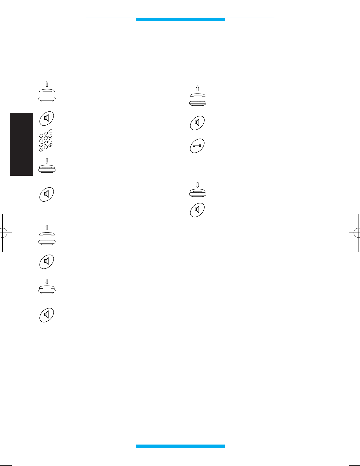
Call on local line
Calls can be made in the usual way, just as
though you were using a normal telephone.
Lift the receiver
or
press the hands-free key.
Dial the desired number.
Once the conversation is over,
replace the receiver
or
press the hands-free key.
Answering incoming calls
Lift the receiver
or
press the hands-free key.
Once the conversation is over,
replace the receiver
or
press the hands-free key.
The telephone rings with different frequencies depending on whether the call is a
telephone call or whether it is from the entry
panel.
See section entitled TONES AND FREQUENCIES.
2
3
4
0
5
6
1
7
8
9
Answering calls from entry
panel
and opening the door
Lift the receiver
or
press the hands-free key.
If you want to let the caller in,
press the door lock release button (in the case of bpt telepho-
nes; for other telephones, consult the summary table).
Replace the receiver
or
press the hands-free key.
NOTE. If the interface is programmed with
the FLASH INTERCEPTION function disabled, the control will not work using a standard multifrequency set whilst communication on the local telephone line.
Page 41
FUNCTIONS
39
ENGLISH
Self-connection on entry panel
The entry panel can be activated for any of
the following needs:
• audio and video monitoring of the entran-
ce (where the entry panel features a
camera);
• exchanging entry panels;
• releasing door lock.
NOTE. Self-connection is only possible
when the set is combined with the video
module XV/200 and when the video entry
system is not engaged.
Interlocutor switching
This function enables the user, whilst communicating with an outside line or the entry
panel, to answer a call on the other line,
putting the current conversation on hold.
The interlocutor put on hold hears a tone
advising him/her of the current hold status.
NOTE. During the conversation, a sound
advise the user of the incoming call.
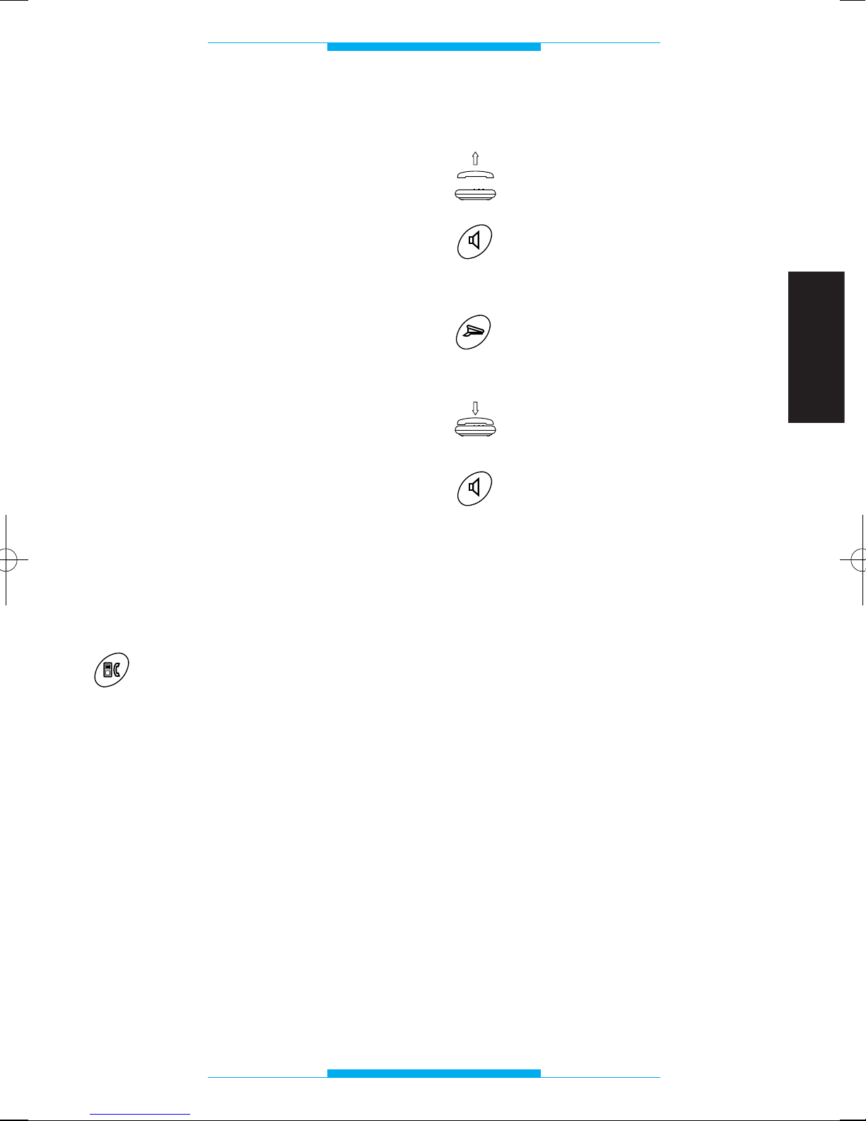
In order to switch between interlocutors
during a conversation:
Press the entry handset/
telephone transfer key (in the
case of bpt telephones; for
other telephones, consult the
summary table).
NOTE. If the interface is programmed with
the FLASH INTERCEPTION function disabled, the control will not work using a standard multifrequency set whilst communicating on the local telephone line.
Porter call
Lift the receiver
or
press the hands-free key.
Wait for the dial tone.
Press the porter call key (in the
case of bpt telephones; for
other telephones, consult the
summary table).
Once the conversation is over,
replace the receiver
or
press the hands-free key.
NOTE. If the interface is programmed with
the FLASH INTERCEPTION function disabled, the control will not work using a standard multifrequency set whilst communicating on the local telephone line.
Page 42
FUNCTIONS
40
ENGLISH
Telephone
auxiliary/stair light control
Lift the receiver
or
press the hands-free key.
Wait for the dial tone.
Press the auxiliary key (in the
case of bpt telephones; for
other telephones, consult the
summary table).
Replace the receiver
or
press the hands-free key.
NOTE. If the interface is programmed with
the FLASH INTERCEPTION function disabled, the control will not work using a DTMF
set whilst communicating on the local
telephone line.
WARNING. In installations featuring conversation privacy, this control is only available if the extension has been called from the
entry panel.
Disabling the incoming
call warning tone
Key in R83 before dialling the telephone number.
The warning tone will remain disabled for
the entire duration of the call.
Use this function when a modem connection is made. If you want the disabling to be
automatic, add the series of digits !83, (see
the software instructions for the telephone
connection).
Accessing in DTMF services
of telephone company
Access is always possible when the interface’s FLASH INTERCEPTION is disabled,
whilst it is only possible during communication with the local telephone line, with no
incoming call from the entry panel, when
the FLASH INTERCEPTION is enabled.
3
8
R
Page 43
FUNCTIONS
41
ENGLISH
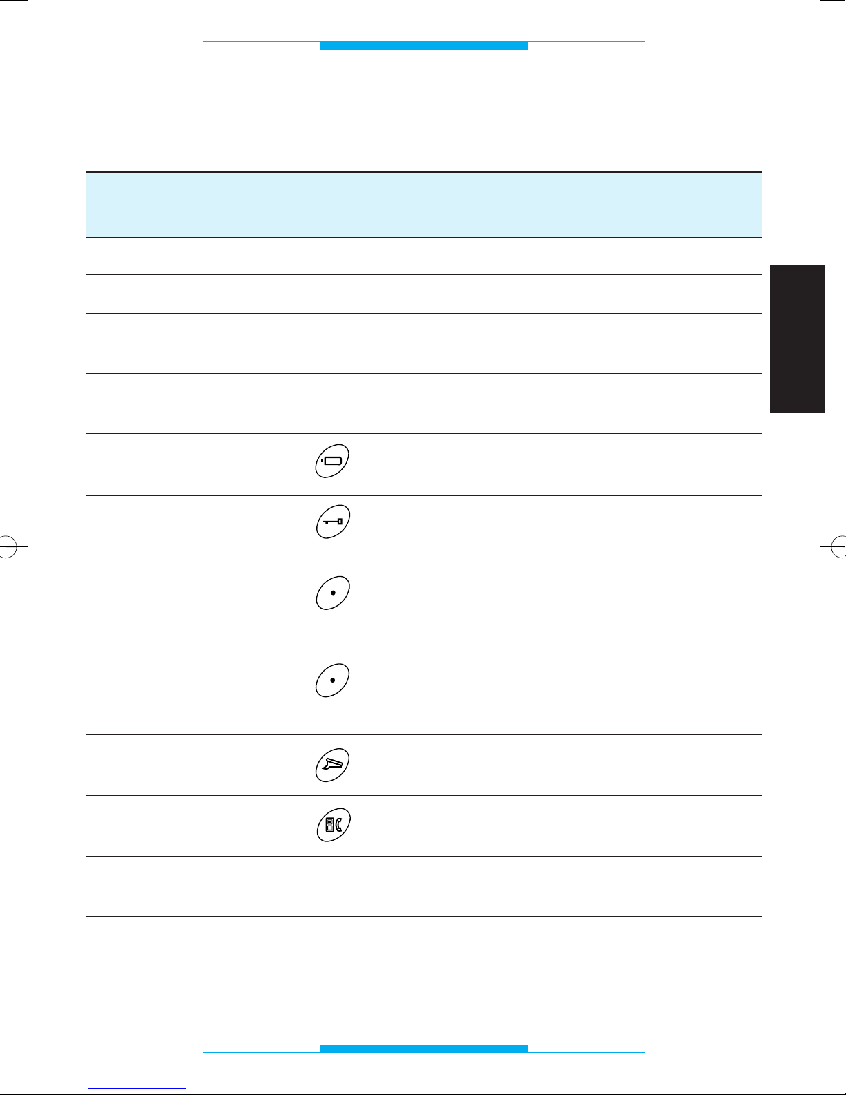
BPT XT/200 MULTIFREQUENCY DECADIC
TELEPHONE TELEPHONE TELEPHONE
PROGRAMMING yes yes not possible
LOCAL CALL direct direct direct
RECEPTION yes yes yes
LOCAL/TELEPHONE CALLS
ACCESS TO DTMF yes yes not possible
SERVICES
SELF-CONNECTION (XV/200) R+86 not possible
DOOR LOCK RELEASE R+85 not possible
AUX./CENTRALIZED STAIR R+88 not possible
LIGHT (output available
in power supplier)
AUX./SINGLE STAIR R+88 not possible
LIGHT (output available
in IT/200) (
1
)
PORTER CALL R+87 not possible
INTERLOCUTOR R+80 not possible
SWITCHING
(1) The AUXILIARY/SINGLE STAIR LIGHT output can also be used in installations with
AUXILIARY/CENTRALIZED STAIR LIGHT by setting dip-switches 4 and 5 to OFF.
Functions available using the bpt telephone
and standard telephone sets
Page 44
42
ENGLISH
Page 45
INHALTSVERZEICHNIS
43
DEUTSCH
Installationsanleitung
Allgemeines . . . . . . . . . . . . . . . . . . . . . . .44
Anmerkungen . . . . . . . . . . . . . . . . . . . . .45
Installation . . . . . . . . . . . . . . . . . . . . . . . .46
Anschlüsse . . . . . . . . . . . . . . . . . . . . . . .47
Inbetriebnahme . . . . . . . . . . . . . . . . . . . .48
Programmierung . . . . . . . . . . . . . . . . . . .49
- Standardkonfiguration . . . . . . . . . . . . .49
- Beginn und Ende der
Programmiervorgänge . . . . . . . . . . . . .49
- Betriebsart Mithörsperre . . . . . . . . . . .49
- Dauer des an der Haussprechanlage
geführten Gesprächs . . . . . . . . . . . . . .50
- Analoge oder codierte Modalität . . . . .50
- Code IT/200 in Block-/Bedienerformat
und codierte Moduseingabe . . . . . . . .51
- Code IT/200 in progressivem
Format und codierte Moduseingabe . .51
- Dauer der Türöffnersteuerung . . . . . . .52
- Flasherkennungsmodus . . . . . . . . . . . .52
- Flash-Auffangfunktion . . . . . . . . . . . . .53
- Telefon mit Monitorkombination . . . . . .53
- Wiederherstellung der
Standardkonfiguration . . . . . . . . . . . . .54
Technische Daten . . . . . . . . . . . . . . . . . .55
Töne und Rhythmen . . . . . . . . . . . . . . . .56
- Signaltöne . . . . . . . . . . . . . . . . . . . . . .56
- Anrufrhythmen . . . . . . . . . . . . . . . . . . .56
Bedienungsanleitung
Glossar . . . . . . . . . . . . . . . . . . . . . . . . . .57
Funktionen . . . . . . . . . . . . . . . . . . . . . . .58
- Anruf auf Ortsleitung . . . . . . . . . . . . . .58
- Beantwortung der
eingehenden Anrufe . . . . . . . . . . . . . .58
- Beantwortung des Anrufs von der
Außenstation und Türöffnen . . . . . . . . .58
- Selbsteinschaltung auf
der Außenstation . . . . . . . . . . . . . . . . .59
- Wechsel des Gesprächsteilnehmers . .59
- Pförtneranruf . . . . . . . . . . . . . . . . . . . . .59
- Steuerung der
Zusatzfunktion/Treppenlicht
vom Telefon aus . . . . . . . . . . . . . . . . . .60
- Ausschaltung der Tonmeldung
des ankommenden Anrufs . . . . . . . . . .60
- Zugang zu den Servicefunktionen
DTMF der Telefongesellschaft . . . . . . .60
- Durch das bpt Telefon und die
Standardtelefone
zugängliche Funktionen . . . . . . . . . . . .61
Page 46
ALLGEMEINES
44
DEUTSCH
Die Telefonschnittstelle ermöglicht den
Anschluß eines Telefonapparats an die
codierte oder uncodierte Leitung der Videound Haussprechanlage der Serie 200 und
100. Über die Benutzung des bpt-Telefons
hinaus können dank dieser Schnittstelle
normale IWV- oder MFV-Telefonapparate,
Handys, Anrufbeantworter, Modems, PABX,
usw., benutzt werden.
Das Gerät besteht aus einer Basisplatine
sind einer Züsatztaste mit den für die
Programmierung notwendigen DIL-Sc halter. Des Gehäuse hat die Abmessüngen
von 8 DIN-Einheiten.
Basisfunktionen
• Direktzugang zu der Amtsleitung.
• Anschluß an die Videosprechanlage der
Serie 200 mit Selbsteinschaltfunktion
(falls dem Monitormodul zugeordnet).
• Anschluß an die Videosprechanlage der
Serie 100.
• Anschluß an die Haussprechanlage mit
oder ohne Mithörsperre.
• Mithörsperre für BPT-Anlagen.
• Integrierte und codierte Schnittstelle.
• Telefongespräch auch bei fehlender
Stromversorgung.
• Rufunterscheidung der Außenstation/
Telefonleitung.
• Funktion Türöffner.
• Zusatzfunktion/Treppenlicht.
• Pförtneranruf.
• Warteschleife (Ortsgespräch/Gespräch
mittels Haussprechanlage).
• Schutzvorrichtung der Telefonleitung.
• Programmierung der Schnittstelle durch
das Telefon.
• Versorgung aus dem Stromnetz.
Page 47
ANMERKUNGEN
45
DEUTSCH
Die Anmerkungen der nachfolgenden
Anleitung aufmerksam durchlesen, da sie
wichtige Sicherheitshinweise über die
Benutzung, Installation und Wartung liefern.
Verpackung abnehmen und sicherstellen,
daß das Gerät einwandfrei ist.
Die Verpackungsteile (Plastikbeutel, Schaumpolystyrol, etc.) müssen außerhalb der
Reichweite von Kindern aufbewahrt werden,
da diese eine Gefahrenquelle darstellen können.
Die Verpackungsteile nicht in die Umwelt freisetzen, sondern sich an die geltenden
Gesetze halten.
Der Anlagenbau muß den geltenden
Sicherheitsvorschriften entsprechen.
Telefonkabel nicht zusammen mit elektrischen Kabeln legen.
Gerät nicht an einem staubigen Ort und fern
von Geräten, die elektrische Hochfrequenzstörungen verursachen können, wie
Schweißapparate, elektrische Motoren,
Mikrowellenherd, Klimaanlagen, etc. aufstellen.
Netzseitig ist ein Fehlerstromschalter einzüsetzen.
Sich vor dem Anschluß des Apparats vergewissern, daß die Daten auf dem Schild
denen des Versorgungsnetzes entsprechen.
Dieses Gerät ausschließlich für die eigens
hierfür gedachte Benutzung gebrauchen;
eine Zweckentfremdung ist unangebracht
und somit gefährlich.
Der Hersteller übernimmt keine Haftung für
eventuelle Schäden, die auf eine
Zweckentfremdung, eine falsche oder
unvernünftige Bedienung zurückzuführen
sind.Vor jeglicher Reinigung oder
Instandhaltung ist der Apparats durch die
Öffnung des Anlagenschalters vom
Stromnetz zu trennen.
Bei Defekten und/oder Störungen ist der
Apparat von der Stromversorgung zu trennen; nicht umrüsten.
Im Falle einer Reparatur sich ausschließlich
an eine vom Hersteller dazu ermächtigte
Kundendienststelle wenden.
Die mangelnde Beachtung des oben
Genannten kann die Sicherheit des Geräts
beeinträchtigen.
Der Installateur muß sich vergewissern, daß
die für den Benutzer erforderlichen
Informationen auf der dafür vorgesehenen
Stelle auf den Geräten vorhanden sind.
Alle Anlagengeräte dürfen ausschließlich
für die hierfür gedachte Benutzung verwendet werden.
Page 48
INSTALLATION
46
DEUTSCH
Der Apparat, der sich in einem Gehäuse zu
8 DIN-Einheiten, flach, befindet, kann in
Kästen mit DIN-Schienen (EN 50022) ohne
Klemmenabdeckungen eingebaut werden.
Für die Außenabmessungen siehe Abb. 1A.
Auch ist die Wandmontage, mit
Klemmenabdeckungen und der Benutzung
der mitgelieferten DIN-Schiene möglich.
Für die Außenabmessungen siehe Abb. 1B.
43,5
45
7,5
57
140
106
A
B
64,5
140
145
Abb. 1
Page 49
ANSCHLÜSSE
47
DEUTSCH
Klemmenabdeckungen abnehmen, um die
Klemmleisten zu erreichen. Für den
Telefonanschluß empfiehlt es sich, ein
Telefonkabel mit einen Qüerschnitt von 0,6
mm zu verwenden.
Maximaler Abstand zwischen Telefonschnittstelle und Telefon: 100 m.
HINWEIS. Das Gerät darf nur an analogen
und nicht an digitalen ISDN-Telefonleitungen angeschlossen werden.
Belegung
der Klemmleisten
Klemmleiste T (Telefonleitung)
ae Ortsleitung
be Ortsleitung
au Telefon
bu Telefon
Klemmleiste C (vom Netzgerät)
5 Masse
6 Eingang Monitorstromversorgung
7 Anruf
8 Audio von Außenstation
9 Audio zur Außenstation
12 Pförtneranruf
22 Zusatzfunktion/Treppenlicht
Klemmleiste M (zur Innensprechstelle)
5 Masse
6 Ausgang Monitorstroversorgung
7 Anruf
8 Audio von Außenstation
9 Audio zur Außenstation
Klemmleiste A
~
Netz
~
ACHTUNG. ES WIRD EMPFOHLEN, DIE
TELEFONLEITUNG UND DIE NETZSTROMVERSORGUNG VOR ÜBERSPANNUNGEN DURCH DEN LEITUNGSSCHUTZSCHALTER LP/MT ZU
SCHÜTZEN.
A
C
5
6
7
8
9
12
T
ae
be
au
bu
M
22
SW1
5
6
7
8
9
ON
OFF
ON
1
2
3
4
56
Abb. 2
Abb. 3
TL
IT/200
T
bu
au
be
ae
A
M
5
6
7
8
9
LP/MT
M3
M4
au
bu
M2
ae
be
56789
C
M1
F2
F1
12 22
Page 50
DIP-SWITCH - EINSTELLUNG
DIP-SWITCH HAUSSPRECHANLAGE VIDEOSPRECHANLAGE VIDEOSPRECHANLAGE
SYSTEM 100 SYSTEM 200
SW1 ON ON ON
SW2 OFF OFF ON
SW3 ON OFF ON
SW4 ON OFF ON
SW5 OFF ON OFF
SW6 ON OFF ON
Die Überbrückungsklemme SW1 wird nur während des PROGRAMMIER-Vorgangs auf OFF gestellt.
INBETRIEBNAHME
48
DEUTSCH
Der Apparat ermöglicht den Anschluß an
die folgenden BPT-Anlagentypen:
- herkömmliche Haussprechanlage
- Haussprechanlage mit Mithörsperre
- Videosprechanlage der Serie 100
- Videosprechanlage der Serie 200
- Elektronischer oder codierter Anruf
Je nach Anlagentyp (Abb. 3) sind die 6 DILSchalter (Abb. 2) einzüstellen.
Über die Einstellung der Dip-Switch hinaus
muß - zur Wahl des Anlagentyps - der
Apparat auch durch das Telefon programmiert werden (siehe PROGRAMMIERUNG).
Die Einstellung des Apparat ermöglicht
den Einbau in Videosprechanlagen der
Serie 200.
ACHTUNG. Für Haussprechanlagen ohne
Mithörsperre hat die Programmierung des
Geräts nach dem auf Seite 49 angezeigten
Verfahren zu erfolgen.
Abb. 3
Page 51
49
DEUTSCH
PROGRAMMIERUNG
Standardkonfiguration
• Flasherkennungsmodus: freigegeben.
• Mithörsperre: eingeschaltet.
• Dauer des an der Haussprechanlage
geführten Gesprächs: 60 Sekunden.
• Dauer des Modus Türöffnen: 1 Sekunde.
• Modalität: Anlagen mit Analoganruf.
• Programmierter Code für einen Anschluß
an Anlagen mit codiertem Anruf: 80155.
• Flash-Auffangdienst: ausgeschaltet.
• Monitor: Kombination mit Telefon: XV/200.
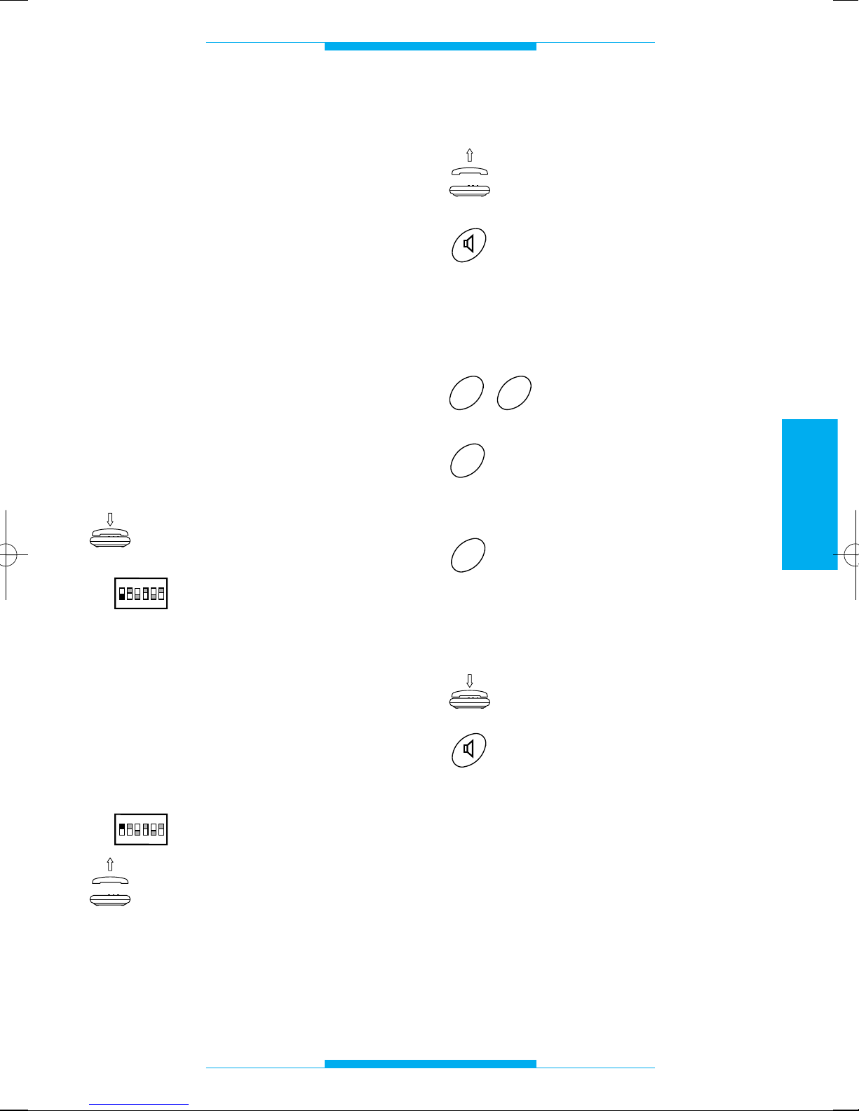
Beginn und Ende der
Programmiervorgänge
Zur Programmierung durch das Telefon,
das an die Telefonschnittstelle angeschlossen ist:
Sich vergewissern, daß der
Telefonhörer aüfgelegt ist.
Dip-Switch 1 auf OFF stellen.
Während dieses Vorgangs können eine
oder mehrere aufeinanderfolgende Programmierungen durchgeführt werden.
Die Eingabe der Programmiercodes ist während der Pause des Programmiertons
auszuführen.
Um die Programmierung zu beenden:
Dip-Switch 1 auf ON stellen.
Bei Vorgangsende muß,
durch das Abheben des
Hörers oder Betätigung der
Taste Freisprechfunktion,
das Freizeichen der
Telefonlinie hörbar sein.
ON
OFF
ON
1
2
3
4
56
ON
OFF
ON
1
2
3
4
56
Betriebsart Mithörsperre
Hörer abnehmen
oder
Taste Freisprechfunktion
drücken.
Nach diesem Vorgang muß ein doppelter
Ton hörbar sein, der zum Programmierungsbeginn auffordert.
29 eingeben.
Für die Betriebsart Anlage
ohne Mithörsperre 0 eingeben
oder
1 für die Betroebsart Anlage
mit Mithörsperre.
Am Ende muß ein dreifacher Bestätigungston hörbar sein.
Hörer wieder aüflegen
oder
Taste Freisprechfunktion
drücken.
1
0
9
2
Page 52
50
DEUTSCH
PROGRAMMIERUNG
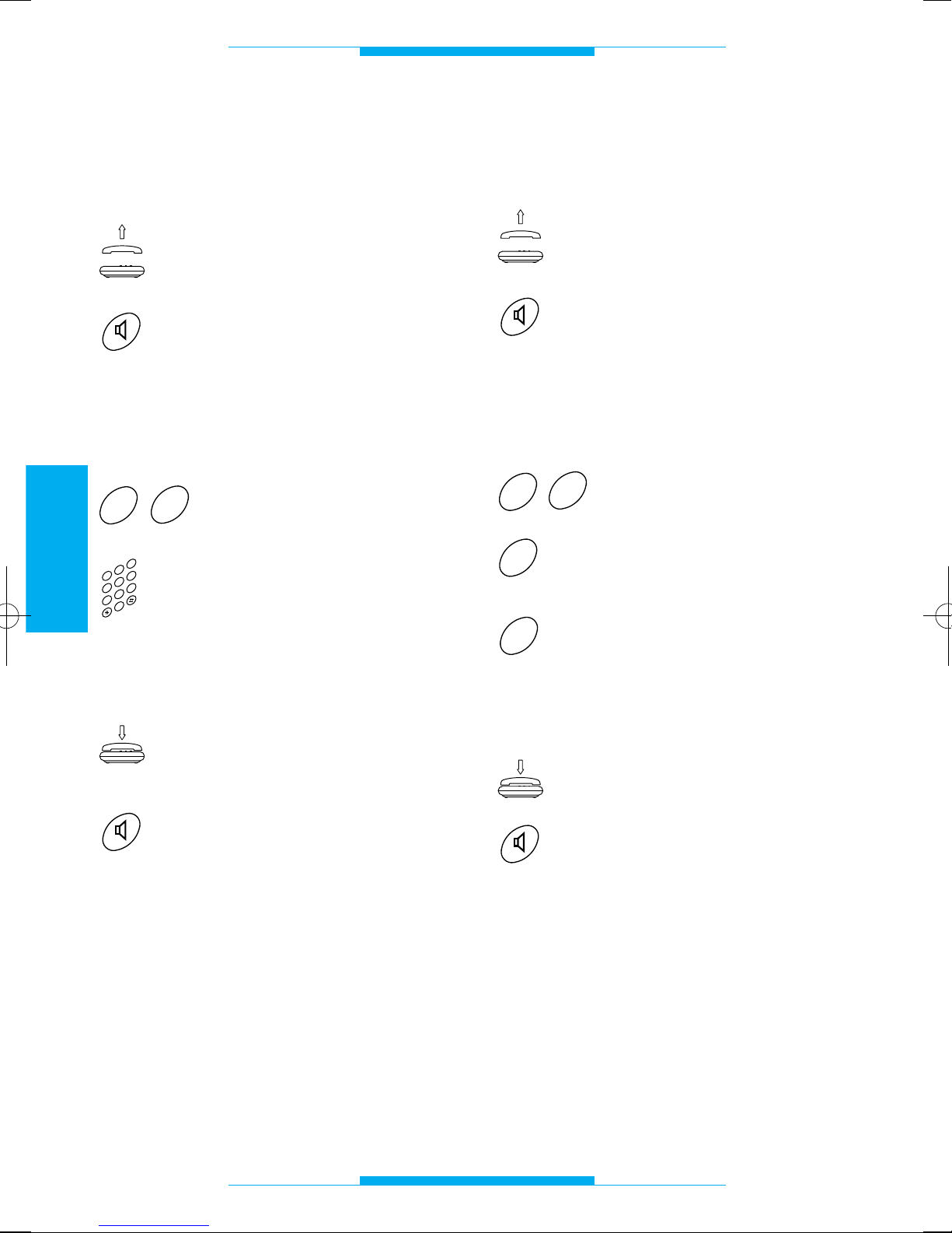
Dauer des an der
Haussprechanlage geführten
Gesprächs
Hörer abnehmen
oder
Taste Freisprechfunktion
drücken.
Nach diesem Vorgang muß ein doppelter
Ton hörbar sein, der zum Programmierungsbeginn auffordert.
27 eingeben.
Gesprächsdauer (von 10
bis 99 Sekunden) eingeben,
z.B. 20 für 20 Sekunden.
Am Ende muß ein dreifacher Bestätigungston hörbar sein.
Mikrotelefon wieder einhängen
oder
Taste Freisprechfunktion
drücken.
ANMERKUNG. Die Veränderung der
Zeiteingabe ist nur in den Haussprechanlagen ohne Mithörsperre (z.B. mit A/200R)
möglich.
2
3
4
0
5
6
1
7
8
9
7
2
Analoge oder codierte Modalität
(siehe den digitalen Außenstationen beiliegende Anleitungen)
Mikrotelefon abnehmen
oder
Taste Freisprechfunktion
drücken.
Nach diesem Vorgang muß ein doppelter
Ton hörbar sein, der zum Programmierungsbeginn auffordert.
62 eingeben.
Für die Modalität analoge
Anlage 0 eingeben (
1
)
oder
1 für die Modalität codierte
Anlage eingeben.
Am Ende muß ein dreifacher Bestätigungston hörbar sein.
Hörer wieder aüflegen
oder
Taste Freisprechfunktion
drücken.
(
1
)
Diese Programmierung ist nur dann
nötig, wenn die zuvor durch digitale Codes
programmierte Schnittstelle wieder konfiguriert werden soll.
1
0
2
6
Page 53
51
DEUTSCH
PROGRAMMIERUNG
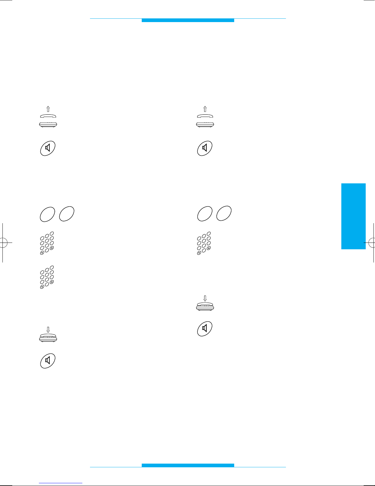
Code IT/200 in
Block-/Bedienerformat und
codierte Moduseingabe
(siehe den digitalen Außenstationen beiliegende Anleitungen)
Hörer abnehmen
oder
Taste Freisprechfunktion
drücken.
Nach diesem Vorgang muß ein doppelter
Ton hörbar sein, der zum Programmierungsbeginn auffordert.
60 eingeben.
Blockcode (von 00 bis 80)
eingeben, z.B. 39.
Bedienercode (von 000 bis
161) eingeben, z.B. 052.
Am Ende muß ein dreifacher Bestätigungston hörbar sein.
Hörer wieder aüflegen
oder
Taste Freisprechfunktion
drücken.
2
3
4
0
5
6
1
7
8
9
2
3
4
0
5
6
1
7
8
9
0
6
Code IT/200 in
progressivem Format und
codierte Moduseingabe
(siehe den digitalen Außenstationen beiliegende Anleitungen)
Hörer abnehmen
oder
Taste Freisprechfunktion
drücken.
Nach diesem Vorgang muß ein doppelter
Ton hörbar sein, der zum Programmierungsbeginn auffordert.
61 eingeben.
Bedienercode (von 00000
bis 13121), z.B. 01523.
Am Ende muß ein dreifacher Bestätigungston hörbar sein.
Hörer wieder aüflegen
oder
Taste Freisprechfunktion
drücken.
2
3
4
0
5
6
1
7
8
9
1
6
Page 54
52
DEUTSCH
PROGRAMMIERUNG
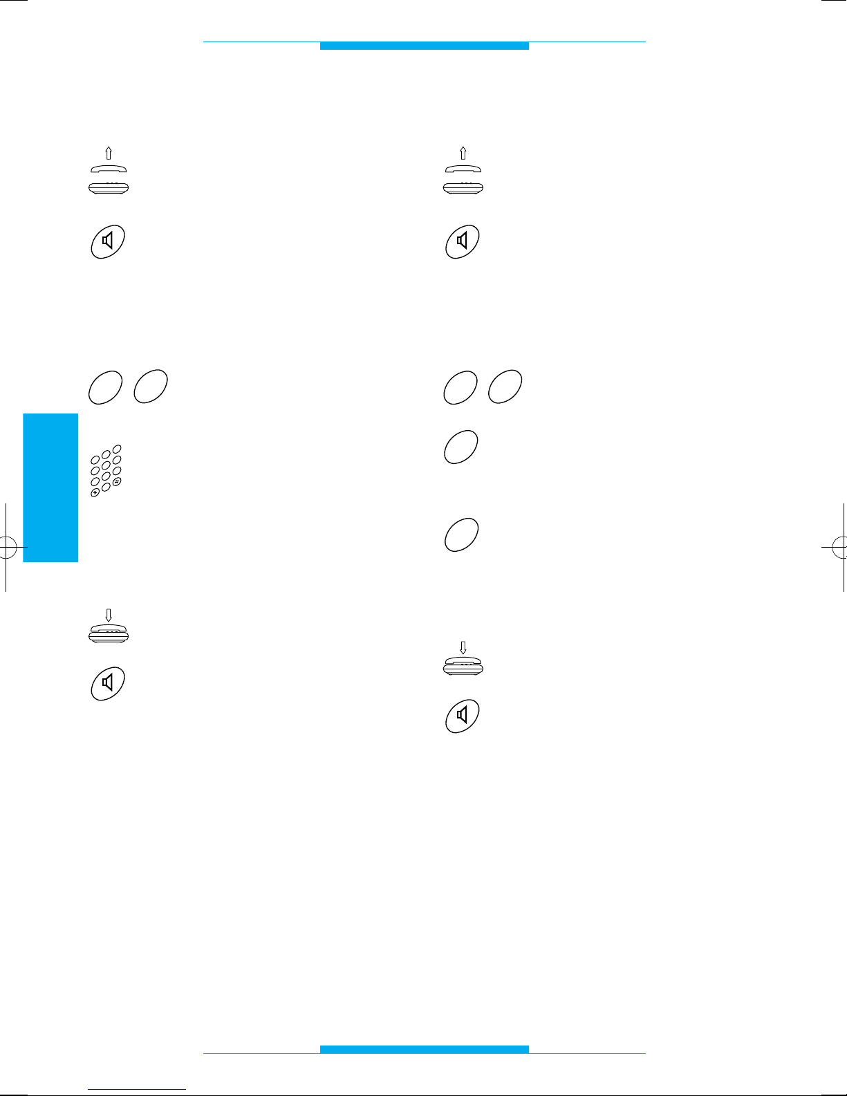
Dauer der Türöffnersteuerung
Hörer abnehmen
oder
Taste Freisprechfunktion
drücken.
Nach diesem Vorgang muß ein doppelter
Ton hörbar sein, der zum Programmierungsbeginn auffordert.
28 eingeben.
Die Dauer der Türöffnersteuerung (von 01 bis 15
Sekunden) eingeben, z.B.
06 für 6 Sekunden.
Am Ende muß ein dreifacher Bestätigungston hörbar sein.
Hörer wieder aüflegen
oder
Taste Freisprechfunktion
drücken.
ANMERKUNG. Diese Funktion kann nur mit
zentralisierten Netzgeräten ohne Zeitschalter (z.B. A/200R oder VA/100.01auf manuelle Steuerung des Elektrotürschlosses eingestellt) betrieben werden.
2
3
4
0
5
6
1
7
8
9
8
2
Flasherkennungsmodus
Hörer abnehmen
oder
Taste Freisprechfunktion
drücken.
Nach diesem Vorgang muß ein doppelter
Ton hörbar sein, der zum Programmierungsbeginn auffordert.
20 eingeben.
Für die freigegebene Flasherkennung 0 eingeben
oder
1 für die lange Flasherken-
nung.
Am Ende muß ein dreifacher Bestätigungston hörbar sein.
Hörer wieder aüflegen
oder
Taste Freisprechfunktion
drücken.
1
0
0
2
Page 55
53
DEUTSCH
PROGRAMMIERUNG
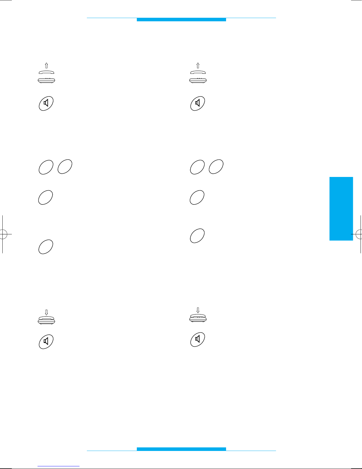
Flash-Auffangfunktion
Hörer abnehmen
oder
Taste Freisprechfunktion
drücken.
Nach diesem Vorgang muß ein doppelter
Ton hörbar sein, der zum Programmierungsbeginn auffordert.
63 eingeben.
Für die ausgeschaltete
Flashauffangfunktion (Anschluß an Telefon XT/200) 0
eingeben
oder
1 für die eingeschaltete
Flashauffangfunktion (Anschluß an allgemeines MFVTelefon).
Am Ende muß ein dreifacher Bestätigungston hörbar sein.
Hörer wieder aüflegen
oder
Taste Freisprechfunktion
drücken.
1
0
3
6
Telefon mit Monitorkombination
Hörer abnehmen
oder
Taste Freisprechfunktion
drücken.
Nach diesem Vorgang muß ein doppelter
Ton hörbar sein, der zum Programmierungsbeginn auffordert.
64 eingeben.
0 eingeben, wenn der
Monitor XV/200 oder
XVC/200 benutzt wird
oder
1 wenn der Monitor IMT/200
oder IMTC/200 benutzt wird.
ANMERKUNG. Bei Anlagen mit Verschiedenen Sprechstellen wählen Sie 1.
Am Ende muß ein dreifacher Bestätigungston hörbar sein.
Hörer wieder aüflegen
oder
Taste Freisprechfunktion
drücken.
1
0
4
6
Page 56
54
DEUTSCH
PROGRAMMIERUNG
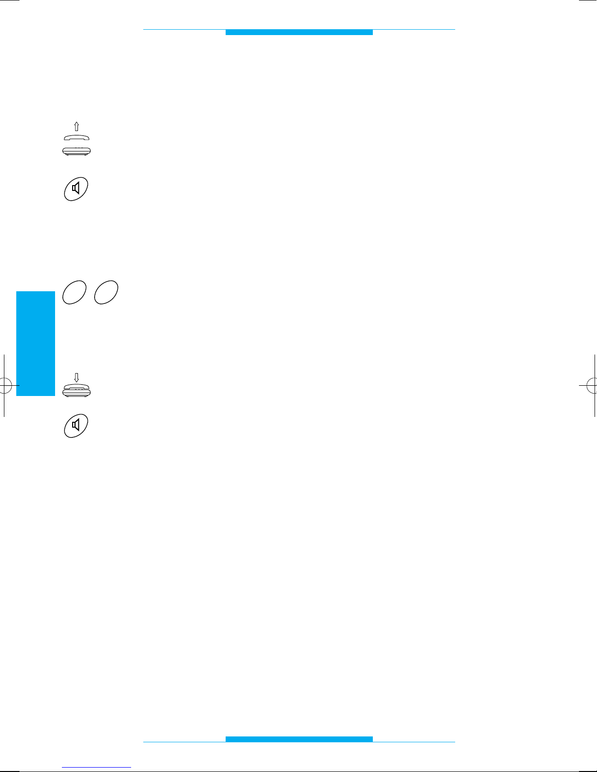
Wiederherstellung der
Standardkonfiguration
Hörer abnehmen
oder
Taste Freisprechfunktion
drücken.
Nach diesem Vorgang muß ein doppelter
Ton hörbar sein, der zum Programmierungsbeginn auffordert.
00 eingeben.
Am Ende muß ein dreifacher Bestätigungston hörbar sein.
Hörer wieder aüflegen
oder
Taste Freisprechfunktion
drücken.
0
0
Page 57
55
DEUTSCH
TECHNISCHE DATEN
• Stromversorgung: 230 V AC, 50 Hz.
• Stromaufnahme: 6 VA max.
• Ausgangsspannung: 24 V.
• Rüfspannüng 50 V eff./50 Hz.
• Max. Länge der Anschlußkabel pro
Sprechgarnitur: 100 m (Telefonkabel mit
einem Qüerschnitt von 0,6 mm).
• Anzahl der Sprechgarnituren auf dersel-
ben Leitung: 5 max.
• Wiederherstellbare elektronische Schutz-
vorrichtung.
• Frequenzhub gemäß CCITT-Normen.
• Monitoreinschaltung für die gesamte
Gesprächsdauer.
• Max. Gesprächsdauer an der Haussprech-
anlage: 99 s.
• Einzelanschluß für Treppenlichter (Typ
OPEN COLLECTOR 24 V DC, 50 mA).
• Anschluß für Pförtneranruf.
• Regelbare Flashdauer (R).
• Dauer der Auslösung des Türöffners von
1 bis 15 s.
• Anschluß an die Amtsleitung auch bei
fehlender Stromversorgung.
• Betriebstemperatur: von 0 °C bis +35 °C.
• Relative Luftfeuchtigkeit: 90% ohne
Kondenswasser.
• Schützklasse II.
• Abmessungen: 8 DIN-Einheiten, flach.
• Frequenz der Signaltöne: 375 Hz.
Das Gerät wurde gemäß den Vorschriften
CTR 21 zugelassen und erfüllt die Vorschrift
EN 60950 über die elektrische Sicherheit
und die europäische Richtlinie 89/336/EEC,
durch 93/68/EEC abgeändert, über die elektromagnetische Kompatibilität.
Die europäische Genehmigung wurde von
BZT-ETS CERTIFICATION GmbH erlassen
Page 58
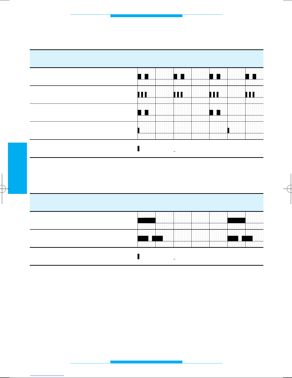
56
DEUTSCH
TÖNE UND RHYTHMEN
FUNKTION
ZEIT (Sekunden)
1234
5
60
FUNKTION
ZEIT (Sekunden)
1
2
3
4
50
Programmierung
Bestätigung Programmierende
Warteschleife
Information
Haussprechanlage
Ortsleitung
6
= Pause= Note
= Pause= Note
Signaltöne
Anrufrhythmen
Page 59
57
DEUTSCH
GLOSSAR
Sprechgarnitur
Ermöglicht die Verbindungsaufnahme zu
der Außenstation und die Steuerung des
Türöffners.
Standard
Dieser Begriff definiert jegliche, vom
Hersteller durchgeführte Voreinstellung
oder Programmierung.
Flash (R)
Durch diesen Tastendruck auf dem Telefon
wird die Schnittstelle auf den Empfang einer
Steuerfunktion vorbereitet.
Amtsleitung
Verbindung, die ein Gespräch zwischen
zwei Teilnehmer am öffentlicher Netz herstellt.
Außenstation
Gibt dem Besucher die Möglichkeit, den
Teilnehmer anzurufen und mit diesem ein
Gespräch zu führen.
Falls mit Videokamera ausgestattet, werden
die bilder der Videosprechanlage ins Haus
gesendet.
Telefon
Ein Apparat, durch den man normalerweise
Telefonanrufe auf der Amtsleitung empfangt
und vornimmt; mit der Zentrale IT/200 kann
es auch als Sprechgarnitur verwendet werden.
IWV-Telefon
Telefon mit Wählscheibe oder auch mit
Nummerntastatur. Die IWV-Wahl erkennt
man daran, daß beim Anwählen einer
Rufnummer in Hörer die Impulse herauszuhören sind.
MFV-Telefon
Es handelt sich um ein Mehrfrequenztelefon, wenn beim Anwählen einer
Rufnummer im Hörer einzelne Töne ünterschielicher Freqüenz zü hören sind.
Videosprechgarnitur
Über die normalen Funktionen der
Sprechgarnitur hinaus zeigt es auf dem
Bildschirm den Besucher, der von der
Außenstation anruft.
Page 60
58
DEUTSCH
FUNKTIONEN
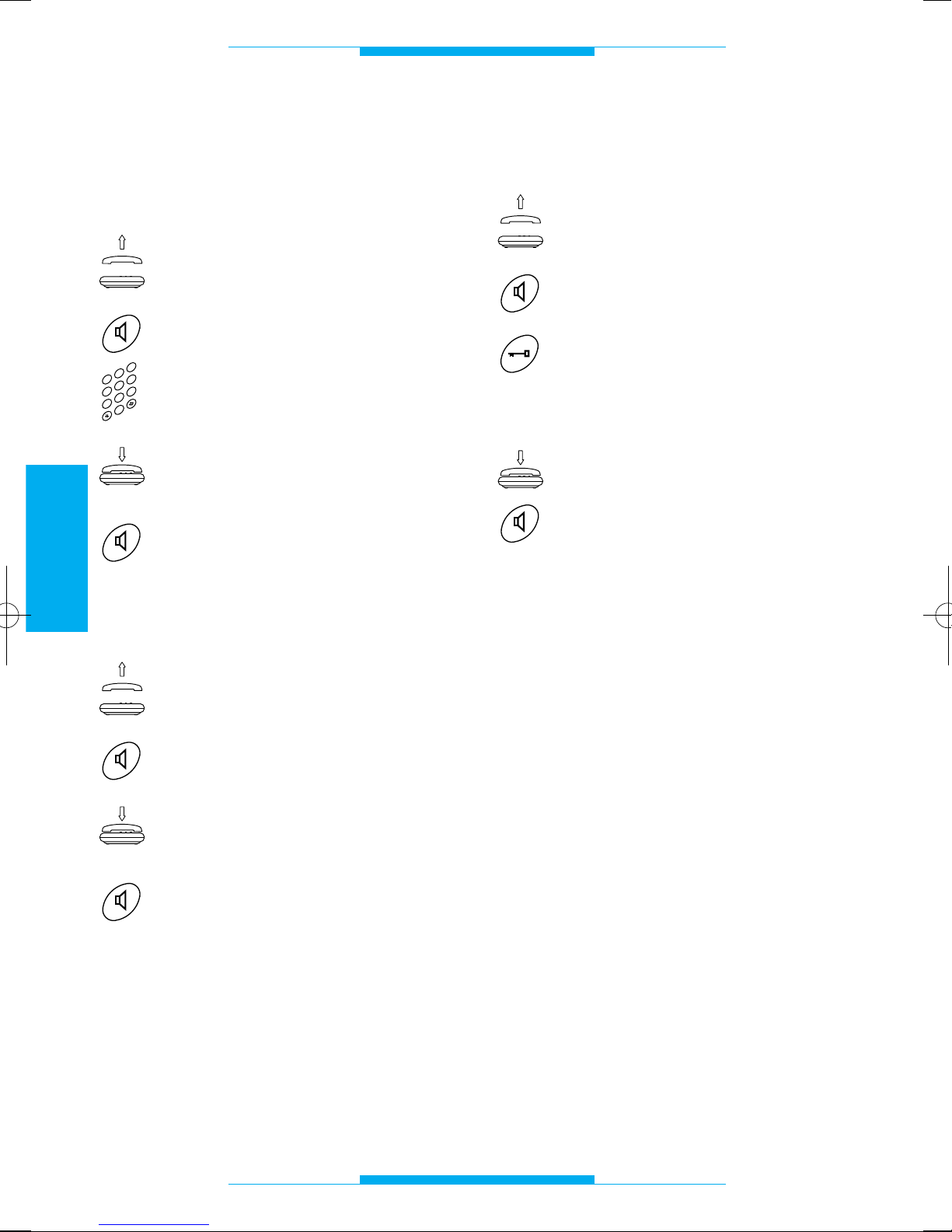
Anruf auf Amtsleitung
Die Anrufe können wie gewohnt, wie mit
jeglichem anderen Apparat, vorgenommen
werden.
Hörer abnehmen
oder
Taste Freisprechfunktion drücken.
Die gewünschte Rufnummer in
die Tastatur eingeben.
Bei Gesprächsende Hörer wieder
aüflegen
oder
Taste Freisprechfunktion drücken.
Beantwortung der
eingehenden Anrufe
Hörer abnehmen
oder
Taste Freisprechfunktion drücken.
Bei Gesprächsende Hörer wieder
aüflegen
oder
Taste Freisprechfunktion drücken.
Das Telefon läutet mit unterschiedlichen
Rhythmen, je nachdem, ob der Anruf von
einer Ortsleitung oder von der Außenstation
kommt.
Siehe Kapitel Klingel- TÖNE UND RHYTHMEN.
2
3
4
0
5
6
1
7
8
9
Beantwortung des Anrufs von
der Außenstation und Türöffner
Hörer abnehmen
oder
Taste Freisprechfunktion drücken.
Falls die anrufende Person eintreten soll, Taste Türöffner (für
bpt-Telefone, für andere Telefone siehe zusammenfassende
Tabelle) drücken.
Hörer wieder aüflegen
oder
Taste Freisprechfunktion drücken.
ANMERKUNG. Wenn die Schnittstelle auf
ausgeschaltete FLASHAUFFANGFUNKTION programmiert ist, kann von einem
Mehrfrequenz-Standardtelefon und bei
bestehender Verbindung mit der Ortsleitung, keine Steuerfunktion ausgesendet
werden.
Page 61
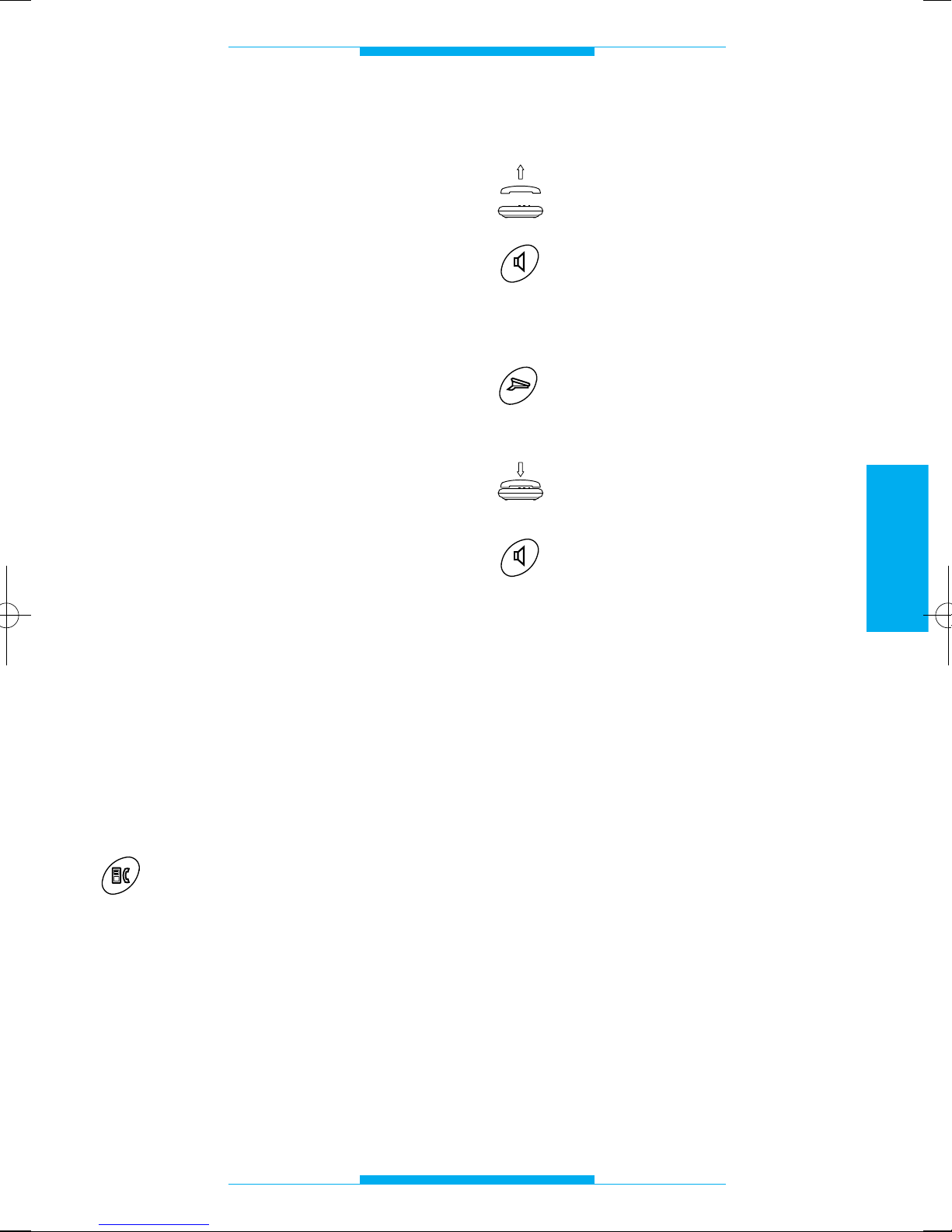
59
DEUTSCH
FUNKTIONEN
Selbsteinschaltung
auf der Außenstation
Die Einschaltung der Außenstation ist infolge
einer der folgenden Erfordernisse möglich:
• die Audio- und Videoüberwachung der
Umgebung (falls die Außenstation über
eine Videokamera verfügt);
• die Umschaltung zwischen den Außen-
stationen;
• die Betätigung des Türöffners.
ANMERKUNG. Die Selbsteinschaltung ist
nur durch die Kombination mit dem
Videomodul XV/200 und bei freier
Videosprechanlage möglich.
Wechsel
des Gesprächsteilnehmers
Durch diese Dientsfunktion kann der Bediener, der mit einer externen Leitung oder der
Außenstation verbunden ist, auf einen Anruf
auf einer anderen Leitung antworten, indem
die bestehende Verbindung geparkt wird.
Ein akustischer Ton meldet dem geparkten
Gesprächsteilnehmer diesen Zustand.
ANMERKUNG. Während des Gesprächs
meldet ein akustischer Hinweis dem
Bediener den eingehenden zweiten Anrüf.
Um während des Gesprächs auf einen
anderen Teilnehmer umzuschalten:
Umschalttaste Sprechgarnitur/
Telefon drücken (für bpt-Telefone,
für andere Telefone siehe zusammenfassende Tabelle).
ANMERKUNG. Wenn die Schnittstelle auf
ausgeschaltete FLASHAUFFANGFUNKTION programmiert ist, kann von einem
Mehrfrequenz-Standardtelefon und bei
bestehender Verbindung mit der Ortsleitung, keine Steuerfunktion ausgesendet
werden.
Pförtneranruf
Hörer abnehmen
oder
Taste Freisprechfunktion drücken.
Ton abwarten, der zum Anwählen auffordert.
Taste Pförtneranruf drücken (für
bpt-Telefone, für andere Telefone siehe zusammenfassende
Tabelle).
Bei Gesprächsende Hörer wieder
aüflegen
oder
Taste Freisprechfunktion drücken.
ANMERKUNG. Wenn die Schnittstelle auf
ausgeschaltete FLASHAUFFANGFUNKTION programmiert ist, kann von einem
Mehrfrequenz-Standardtelefon und bei
bestehender Verbindung mit der Ortsleitung, keine Steuerfunktion ausgesendet
werden.
Page 62
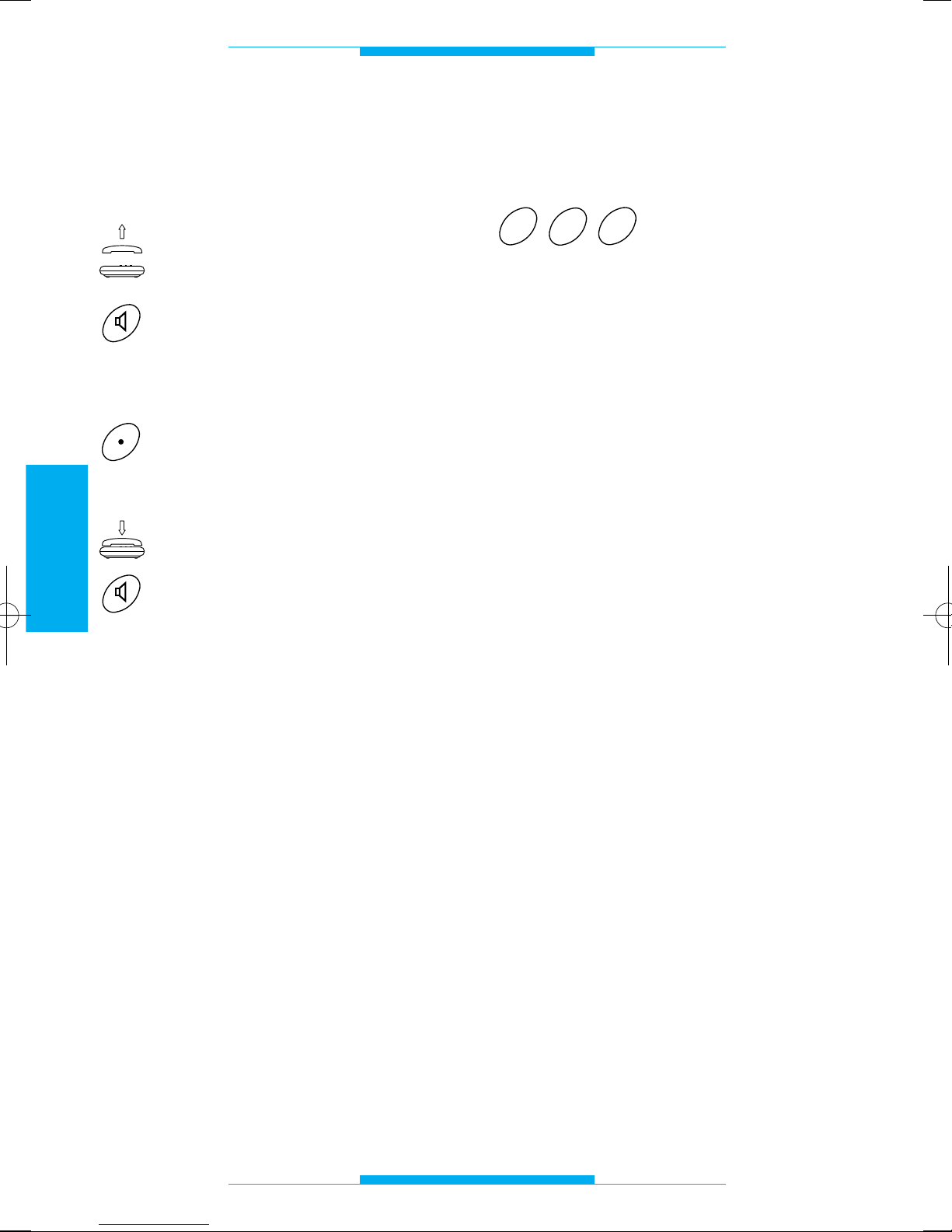
60
DEUTSCH
FUNKTIONEN
Steuerung der
Zusatzfunktion/Treppenlicht
vom Telefon aus
Hörer abnehmen
oder
Taste Freisprechfunktion drücken.
Ton abwarten, der zum Anwählen auffordert.
Zusatztaste drücken (für bpt-
Telefone, für andere Telefone
siehe zusammenfassende Tabelle).
Hörer wieder aüflegen
oder
Taste Freisprechfunktion drücken.
ANMERKUNG. Wenn die Schnittstelle auf
ausgeschaltete FLASHAUFFANGFUNKTION programmiert ist, kann von einem
DTMF-Telefon und bei bestehender
Verbindung mit der Ortsleitung, keine
Steuerfunktion ausgesendet werden.
BEMERKUNG. In Anlagen mit Mithörsperre
ist diese Funktion nur dann verfügbar, wenn
die Sprechgarnitur von der Außenstation
angewählt wurde.
Ausschaltung der Tonmeldung
des ankommenden Anrufs
R83 eingeben und dann
die Telefonnummer wählen.
Während des ganzen Telefonanrufs bleibt
das Meldezeichen ausgeschaltet.
Diese Funktion nur bei einem ModemAnschluß benutzen. Falls die Ausschaltung
automatisch erfolgen soll, ist die
Zeichenfolge !83, (siehe Anweisungen
Telefonanschluß-Software) hinzuzufügen.
Zugang zu den
Servicefunktionen DTMF
der Telefongesellschaft
Der Zugang ist immer dann möglich, wenn
die Schnittstelle als ausgeschaltete FLASHSCHNITTSTELLE konfiguriert wurde; bei
eingeschalteter FLASH-SCHNITTSTELLE
nur dann, wenn eine Verbindung mit der
Amtsleitung besteht und von der
Außenstation der Haussprechanlage keine
Anrufe erfolgen.
3
8
R
Page 63
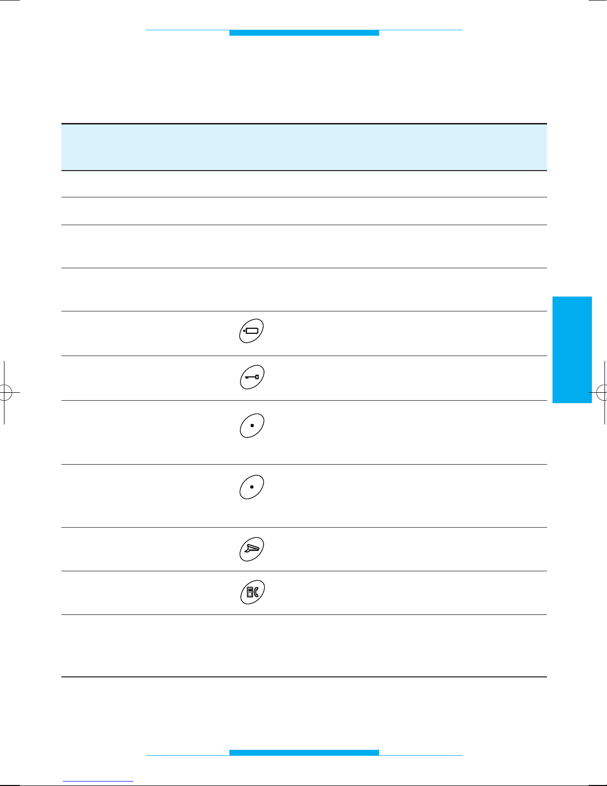
61
DEUTSCH
FUNKTIONEN
BPT-TELEFON MULTIFREQUENZ- IWV-
XT/200 TELEFON TELEFON
PROGRAMMIERUNG ja ja nicht möglich
ORTSGESPRÄCH direkt direkt direkt
EMPFANG VON ORTSGESPRÄ-
ja ja ja
CHEN/TELEFONANRUFEN
ZUGANG ZU DEN DTMF-TELE-
ja ja nicht möglich
KOM SERVICEFUNKTIONEN
SELBSTEINSCHALTUNG (XV/200) R+86 nicht möglich
TÜRÖFFNER R+85 nicht möglich
ZUSATZFUNKTION/TREPPEN-
R+88 nicht möglich
LICHTER (im Netzgerät dafür
verfügbarer Ausgang)
EINZELZUSATZFUNKTION/
R+88 nicht möglich
TREPPENLICHTER (in IT/200
dafür verfuugbarer Ausgang)
(1)
PFÖRTNERANRUF R+87 nicht möglich
WECHSEL DES R+80 nicht möglich
GESPRÄCHSTEILNEHMES
(1) Der Ausgang EINZELZUSATZFUNKTION/TREPPENLICHTER kann auch in Anlagen mit
ZENTRALISIERTEN TREPPENLICHTERN benutzt werden, indem die Dip-Switch Nr. 4 und 5
auf OFF gestellt werden.
Durch das bpt Telefon und die Standardtelefone
zugängliche Funktionen
Page 64
62
DEUTSCH
Page 65
63
FRANÇAIS
SOMMAIRE
Instructions pour l’installateur
Généralités . . . . . . . . . . . . . . . . . . . . . . .64
Conseils . . . . . . . . . . . . . . . . . . . . . . . . .65
Installation . . . . . . . . . . . . . . . . . . . . . . . .66
Connexions . . . . . . . . . . . . . . . . . . . . . . .67
Mise en service . . . . . . . . . . . . . . . . . . . .68
Programmation . . . . . . . . . . . . . . . . . . . .69
- Configuration de default . . . . . . . . . . .69
- Entrée et sortie des opérations
de programmation . . . . . . . . . . . . . . . .69
- Mode secret de conversation . . . . . . .69
- Durée conversation
portier électronique . . . . . . . . . . . . . . .70
- Mode analogique ou codifié . . . . . . . .70
- Code IT/200 en format
bloc/utilisateur et programmation
mode codifié . . . . . . . . . . . . . . . . . . . .71
- Code IT/200 en format progressif
et programmation mode codifié . . . . . .71
- Durée commande ouvre-porte . . . . . . .72
- Mode reconnaissance flash . . . . . . . . .72
- Interception flash . . . . . . . . . . . . . . . . .73
- Type de moniteur à
associer au téléphone . . . . . . . . . . . . .73
- Rétablissement de la
configuration de default . . . . . . . . . . . .74
Caractéristiques techniques . . . . . . . . . .75
Tonalités et rythmes . . . . . . . . . . . . . . . .76
- Tonalités de signalisation . . . . . . . . . . .76
- Rythmes d’appel . . . . . . . . . . . . . . . . .76
Instructions pour l’utilisateur
Glossaire . . . . . . . . . . . . . . . . . . . . . . . . .77
Fonctions . . . . . . . . . . . . . . . . . . . . . . . . .78
- Appel sur ligne urbaine . . . . . . . . . . . .78
- Réponse aux appels en arrivée . . . . . .78
- Réponse à un appel depuis poste
extérieur et ouverture de la porte . . . .78
- Autointroduction sur poste extérieur . .79
- Changement d’interlocuteur . . . . . . . .79
- Appel concierge . . . . . . . . . . . . . . . . .79
- Commande auxiliaire/minuterie
avec téléphone . . . . . . . . . . . . . . . . . .80
- Exclusion signal acoustique
avertissant d’un appel en arrivée . . . .80
- Accès aux services en DTMF
de la compagnie de téléphone . . . . . .80
- Fonctions possibles avec
l’utilisation du téléphone bpt
et avec des téléphones standard . . . .81
Page 66
64
FRANÇAIS
GENERALITES
L’interface téléphonique permet de relier un
appareil téléphonique à la ligne portier
vidéo et portier électronique série 200 et
série 100, qu’elle soit codifiée ou non.
Outre le téléphone bpt, elle permet également d’utiliser des appareils de téléphone
normaux à décades ou DTMF, des téléphones sans fil, un répondeur téléphonique, un
modem, une PABX, etc.
L’appareil sert également à envoyer des
appels à une centrale de conciergerie de
type analogique ou digitale et de commander les fonctions ouvre-porte, minuterie
centralisée, etc.
L’appareil est réalisé dans un boîtier DIN à
8 modules. Il se compose d’un circuit
imprimé de base et d’une carte contenant
les dip-switch pour la programmation et
pour la sélection du type d’installation.
Fonction
• Accès direct à la ligne urbaine.
• Connexion au système portier vidéo série
200 avec fonction d’autointroduction (si
couplé au module moniteur).
• Connexion au système portier vidéo série
100.
• Connexion au système portier électroni-
que avec ou sans secret de conversation.
• Secret de conversation pour installations
BPT.
• Interface codifiée intégrée.
• Communication téléphonique même en
absence d’alimentation secteur.
• Appel diversifié depuis poste exté-
rieur/ligne téléphonique.
• Commande ouvre-porte.
• Commande auxiliaire/minuterie.
• Appel concierge.
• Mise en attente communication (urbai-
ne/portier électronique).
• Protection ligne téléphonique.
• Programmation de l’appareil au moyen du
téléphone.
• Alimentation par le secteur.
Page 67
65
FRANÇAIS
CONSEILS
Lire attentivement les instructions contenues dans le présent livret car elles fournissent d’importantes indications concernant la
sécurité d’emploi, d’installation et d’entretien.
Après avoir sorti l’appareil de son emballage, contrôler s’il est en bon état.
Les éléments de l’emballage (sachets en
plastique, polystyrène expansé, etc.) ne
doivent pas être laissés à la portée des
enfants car ils pourraient être dangereux.
L’élimination de l’emballage doit être fait
conformément aux normes en vigueur.
L’exécution de l’installation doit répondre
aux normes de sécurité en vigueur.
Ne pas faire passer au même endroit les
câbles du téléphone et les câbles électriques.
Installer l’appareil dans un local non poussiéreux, loin de tous appareils pouvant
créer des dérangements électriques de
haute fréquence comme par ex.: soudeuses, moteurs électriques, fours à microondes, climatisateurs, etc.
Il est opportun de prévoir en amont de l’alimentation un interrupteur de coupure et de
protection adéquat.
Avant de connecteur l’appareil, s’assurer
que les données de la plaque signalétique
correspond à celle du réseau de distribution.
Cet appareil ne devra être destiné qu’à
l’emploi pour lequel il a été expressément
conçu. Toute autre utilisation sera considérée comme impropre et dangereuse.
Le constructeur ne sera pas tenu responsable de tous dommages dérivant d’une utilisation inappropriée, erronée et irraisonnée.
Avant d’effectuer toute opération de nettoyage ou d’entretien, couper le courant du
réseau d’alimentation en ouvrant l’interrupteur de l’installation.
En cas de panne et/ou de défaillance de
fonctionnement, couper le courant et ne
pas manipuler l’appareil.
Pour toute réparation, s’adresser uniquement à un centre de service après-vente
agréé.
Le non-respect des indications ci-dessus
peut compromettre la sécurité de l’appareil.
L’installateur doit s’assurer que les informations pour l’utilisateur, quand elles sont prévues, soient présentes sur l’appareil.
Tous les appareils constituant l’installation
devront être destinés exclusivement à l’emploi pour lequel ils ont été conçus.
Page 68
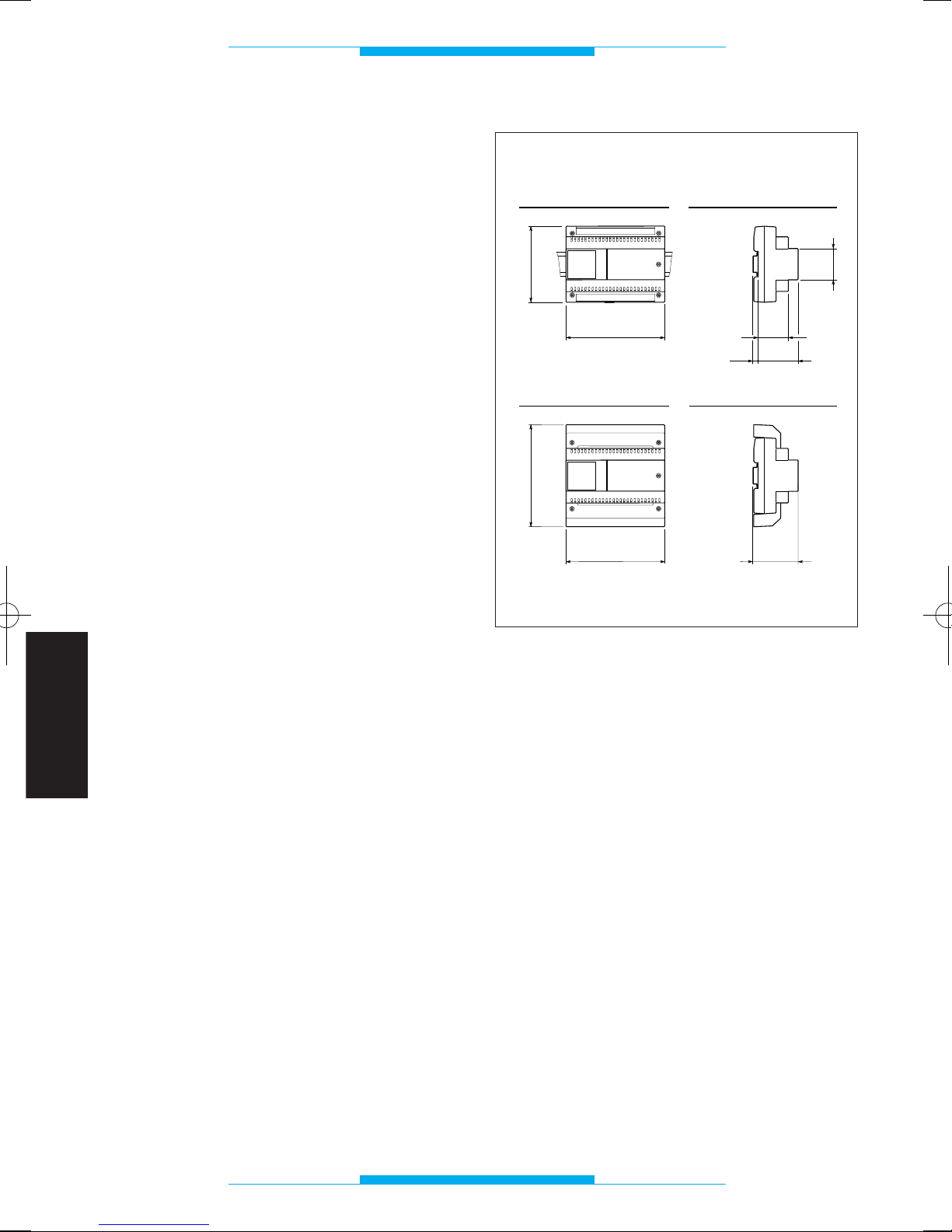
66
FRANÇAIS
INSTALLATION
L’appareil réalisé dans un boîtier à 8 unités
bas, peut être installé sans couvre-bornes
dans des boîtiers munis de rail DIN (EN
50022). Pour les dimensions d’encombrement, voir la fig. 1A.
Ou bien il peut être installé au mur, avec
couvre-bornes, en utilisant le rail DIN fourni
en standard. Pour les dimensions d’encombrement, voir la fig. 1B.
43,5
45
7,5
57
140
106
A
B
64,5
140
145
Fig. 1
Page 69
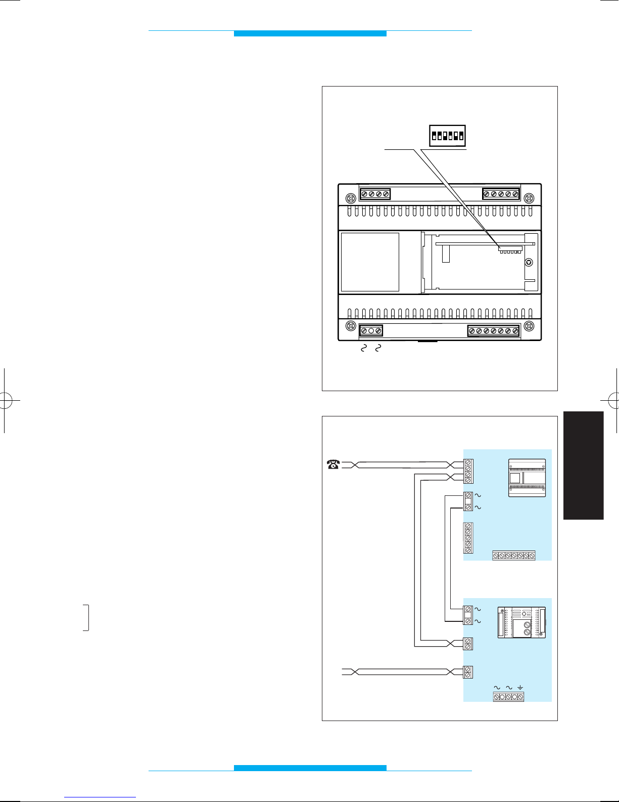
67
FRANÇAIS
CONNEXIONS
Pour accéder aux borniers, enlever les couvre-bornes. Pour la connexion des téléphones, il est conseillé d’utiliser le câble de
6/10.
Distance maximale entre interface téléphonique et téléphone: 100 m.
NOTA. L’appareil ne doit être raccordé que
sur des lignes téléphoniques analogiques et
non pas sur des lignes digitales ISDN.
Fonction
des bornes
Bornier T (ligne téléphonique)
ae ligne urbaine
be ligne urbaine
au téléphone
bu téléphone
Bornier C (depuis alimentation)
5 masse
6 entrée alimentation moniteur
7 appel
8 audio depuis poste extérieur
9 audio au poste extérieur
12 appel conciergerie
22 auxiliaire/minuterie
Bornier M (au poste intérieur)
5 masse
6 sortie alimentation moniteur
7 appel
8 audio depuis poste extérieur
9 audio au poste extérieur
Bornier A
~
secteur
~
ATTENTION. NOUS VOUS CONSEILLONS DE PROTÉGER LA LIGNE
TÉLÉPHONI-QUE ET L'ALIMENTATION
DU SECTEUR CONTRE LES SURTENSIONS AU MOYEN DU PROTECTEUR DE
LIGNE LP/MT.
A
C
5
6
7
8
9
12
T
ae
be
au
bu
M
22
SW1
5
6
7
8
9
ON
OFF
ON
1
2
3
4
56
Fig. 2
Fig. 3
TL
IT/200
T
bu
au
be
ae
A
M
5
6
7
8
9
LP/MT
M3
M4
au
bu
M2
ae
be
56789
C
M1
F2
F1
12 22
Page 70
68
FRANÇAIS
POSITION DES DIP-SWITCH
DIP-SWITCH PORTIER PORTIER VIDEO PORTIER VIDEO
ELECTRONIQUE SYSTEME 100 SYSTEME 200
SW1 ON ON ON
SW2 OFF OFF ON
SW3 ON OFF ON
SW4 ON OFF ON
SW5 OFF ON OFF
SW6 ON OFF ON
Le cavalier SW1 sera positionné sur ON uniquement pendant les opérations de PROGRAMMATION.
MISE EN SERVICE
L’appareil permet d’effectuer la connexion
aux installations BPT suivantes:
- portier électronique conventionnel
- portier électronique avec seret de conversation
- portier vidéo système 100
- portier vidéo système 200
- appel électronique ou codifié
Il est doté de 6 dip-switch (fig. 2) à positionner en fonction du type d’installation
(fig. 3).
Outre la programmation des dip-switch, il
faut également effectuer une programmation avec le téléphone pour le choix du type
d’installation (voir chapitre PROGRAMMATION).
L’appareil est prevú pour être installé dans
des installations portier vidéo système 200.
ATTENTION. Pour des installations de portier électronique sans secret de conversation, il est nécessaire de programmer l’appareil selon les modalités indiquées à la
page 69.
Fig. 3
Page 71
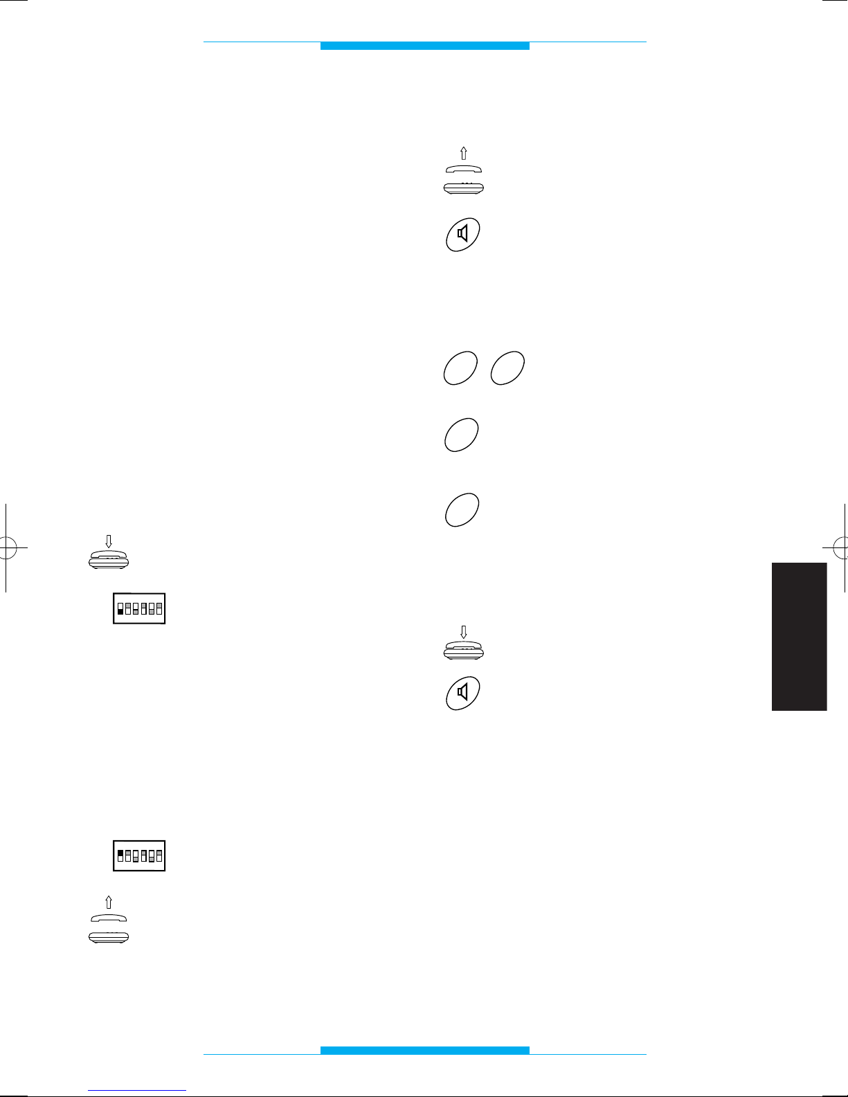
69
FRANÇAIS
PROGRAMMATION
Configuration de default
• Mode reconaissance flash: homologué.
• Secret de conversation: activé.
• Durée de conversation portier électroni-
que: 60 s.
• Durée commande ouvre-porte: 1 s.
• Mode: installation avec appel analogique.
• Code programmé pour connexion dans
des installations avec appel codifié:
80155.
• Interception flash: exclu.
• Type de moniteur associé au téléphone:
XV/200.
Entrée et sortie des opérations
de programmation
Pour entrer en mode programmation
avec le téléphone relié à l’interface
téléphonique:
S’assurer que le récepteur
du téléphone soit accroché.
Positionner le dip-switch 1
sur OFF.
Pendant cette phase, il est possible d’effectuer une ou plusieurs programmations consécutives.
L’entrée des codes de programmation doit
être effectuée pendant la pause de la tonalité de programmation.
Pour sortir de la phase de programmation:
Positionner le dip-switch 1
sur ON.
En fin d’opération, lorsque
l’on soulève le récepteur ou
bien en appuyant sur la touche vive-voix, on doit entendre la tonalité de ligne
téléphonique libre.
ON
OFF
ON
1
2
3
4
56
ON
OFF
ON
1
2
3
4
56
Mode secret de conversation
Soulever le récepteur
ou bien
appuyer sur la touche vive-
voix.
Après cette opération, on doit entendre une
double tonalité invitant à la programmation.
Taper 29.
Taper 0 pour mode installation sans secret
ou bien
1 pour mode installation
avec secret.
Après cette opération, on doit entendre une
triple tonalité de confirmation.
Raccrocher
ou bien
appuyer sur la touche vivevoix.
1
0
9
2
Page 72
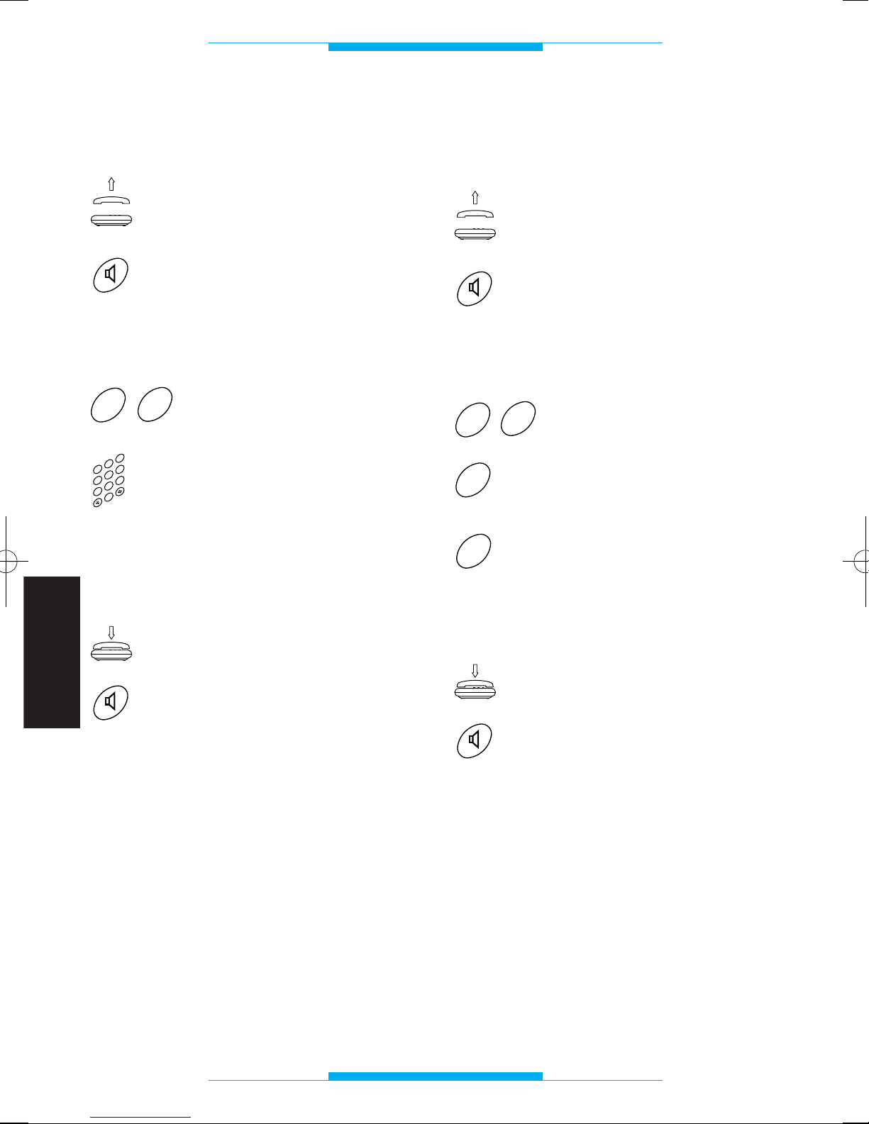
70
FRANÇAIS
PROGRAMMATION
Durée conversation
portier électronique
Soulever le récepteur
ou bien
appuyer sur la touche vive-
voix.
Après cette opération, on doit entendre une
double tonalité invitant à la programmation.
Taper 27.
Taper la durée de la conversation (de 10 à 99 secondes). Ex: 20 pour 20 secondes.
Après cette opération, on doit entendre une
triple tonalité de confirmation.
Raccrocher
ou bien
appuyer sur la touche vivevoix.
NOTE. Le temps pourra être modifié uniquement pour des installations portier électronique sans secret de conversation (ex:
avec A/200R).
2
3
4
0
5
6
1
7
8
9
7
2
Mode analogique ou codifié
(voir instructions jointes aux postes extérieurs
digitaux)
Soulever le récepteur
ou bien
appuyer sur la touche vive-
voix.
Après cette opération, on doit entendre une
double tonalité invitant à la programmation.
Taper 62.
Taper 0 pour mode installation analogique (
1
)
ou bien
1 pour mode installation
codifiée.
Après cette opération, on doit entendre une
triple tonalité de confirmation.
Raccrocher
ou bien
appuyer sur la touche vivevoix.
(
1
)
Cette programmation est nécessaire uniquement au cas où l’on souhaiterait reonfigurer l’interface précédemment programmée avec des codes digitaux.
1
0
2
6
Page 73
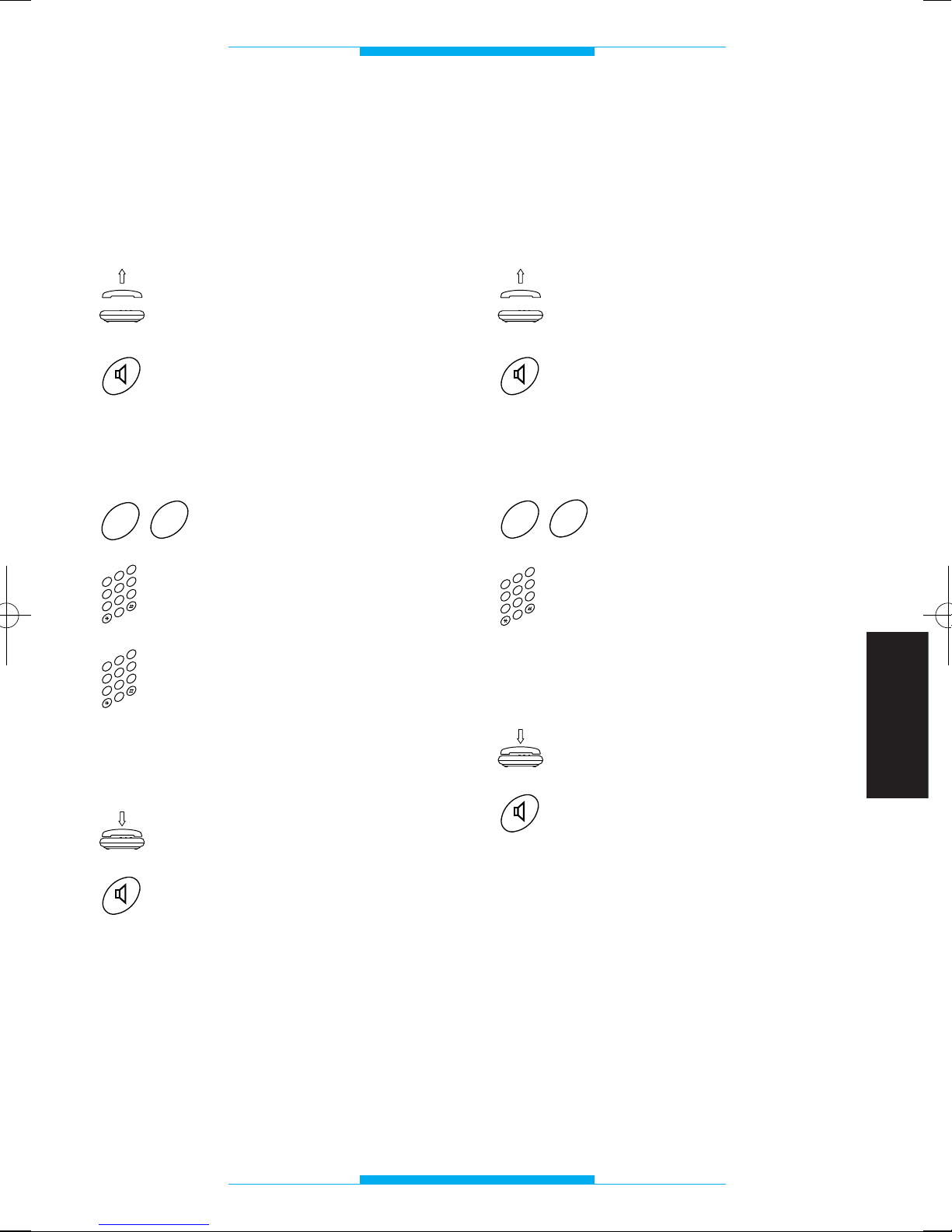
71
FRANÇAIS
PROGRAMMATION
Code IT/200 en format
bloc/utilisateur et
programmation mode codifié
(voir instructions jointes aux postes extérieurs
digitaux)
Soulever le récepteur
ou bien
appuyer sur la touche vive-
voix.
Après cette opération, on doit entendre une
double tonalité invitant à la programmation.
Taper 60.
Taper le code du bloc (de
00 à 80). Ex: 039.
Taper le code utilisateur (de
000 à 161). Ex: 052.
Après cette opération, on doit entendre une
triple tonalité de confirmation.
Raccrocher
ou bien
appuyer sur la touche vivevoix.
2
3
4
0
5
6
1
7
8
9
2
3
4
0
5
6
1
7
8
9
0
6
Code IT/200 en format
progressif et
programmation mode codifié
(voir instructions jointes aux postes extérieurs
digitaux)
Soulever le récepteur
ou bien
appuyer sur la touche vive-
voix.
Après cette opération, on doit entendre une
double tonalité invitant à la programmation.
Taper 61.
Taper le code utilisateur (de
00000 à 13121). Ex: 01523.
Après cette opération, on doit entendre une
triple tonalité de confirmation.
Raccrocher
ou bien
appuyer sur la touche vivevoix.
2
3
4
0
5
6
1
7
8
9
1
6
Page 74
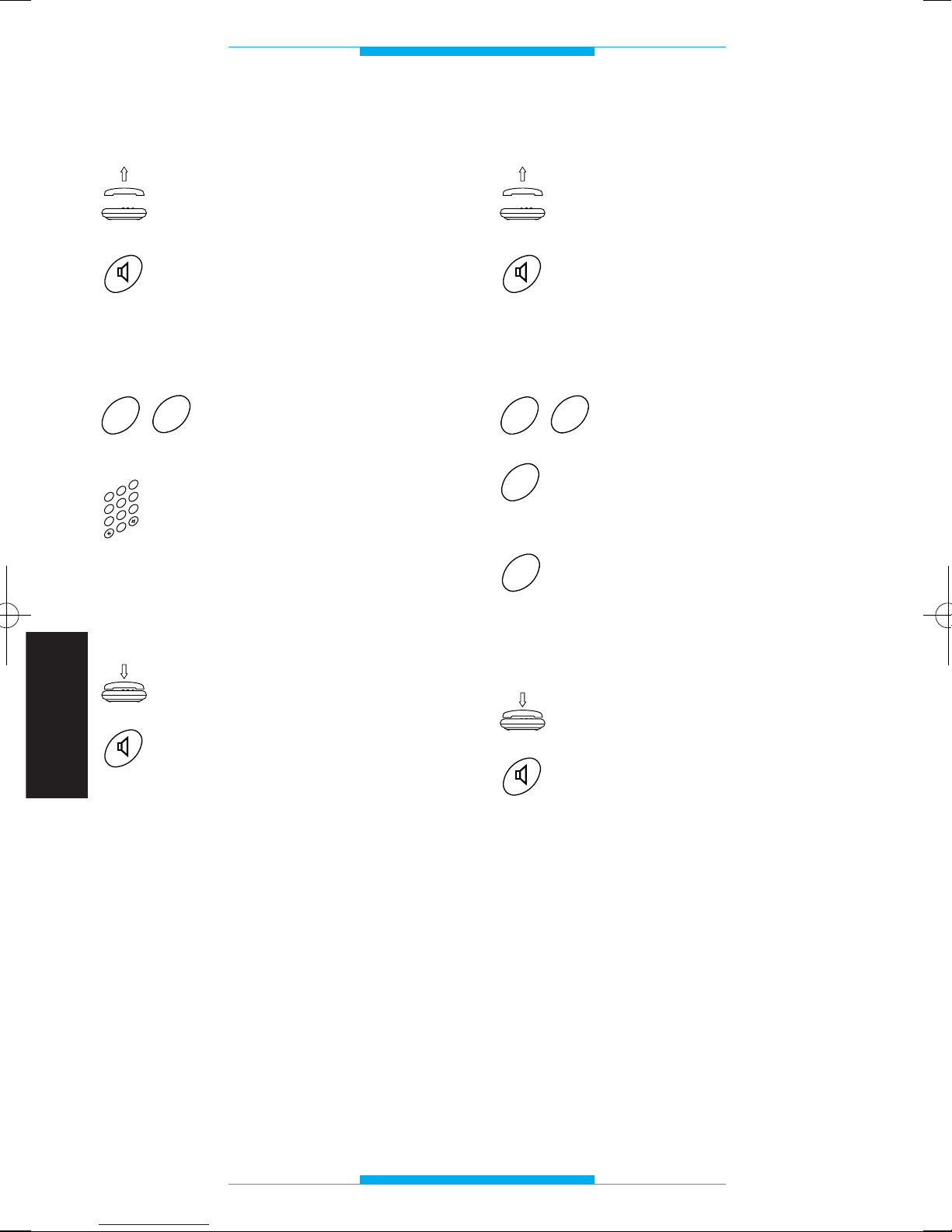
72
FRANÇAIS
PROGRAMMATION
Durée commande ouvre-porte
Soulever le récepteur
ou bien
appuyer sur la touche vive-
voix.
Après cette opération, on doit entendre une
double tonalité invitant à la programmation.
Taper 28.
Taper la durée de la commande ouvre-porte (de 01
à 15 secondes). Ex: 06
pour 6 secondes.
Après cette opération, on doit entendre une
triple tonalité de confirmation.
Raccrocher
ou bien
appuyer sur la touche vivevoix.
NOTE. Il est possible d’utiliser cette fonction uniquement avec des alimentations
sans programmateurs centralisés (ex:
A/200R ou VA/100.01programmé pour la
commande serrure électrique manuelle).
2
3
4
0
5
6
1
7
8
9
8
2
Mode reconnaissance flash
Soulever le récepteur
ou bien
appuyer sur la touche vive-
voix.
Après cette opération, on doit entendre une
double tonalité invitant à la programmation.
Taper 20.
Taper 0 pour reconaissance
flash homologué
ou bien
1 pour reconnaissance
flash long.
Après cette opération, on doit entendre une
triple tonalité de confirmation.
Raccrocher
ou bien
appuyer sur la touche vivevoix.
1
0
0
2
Page 75
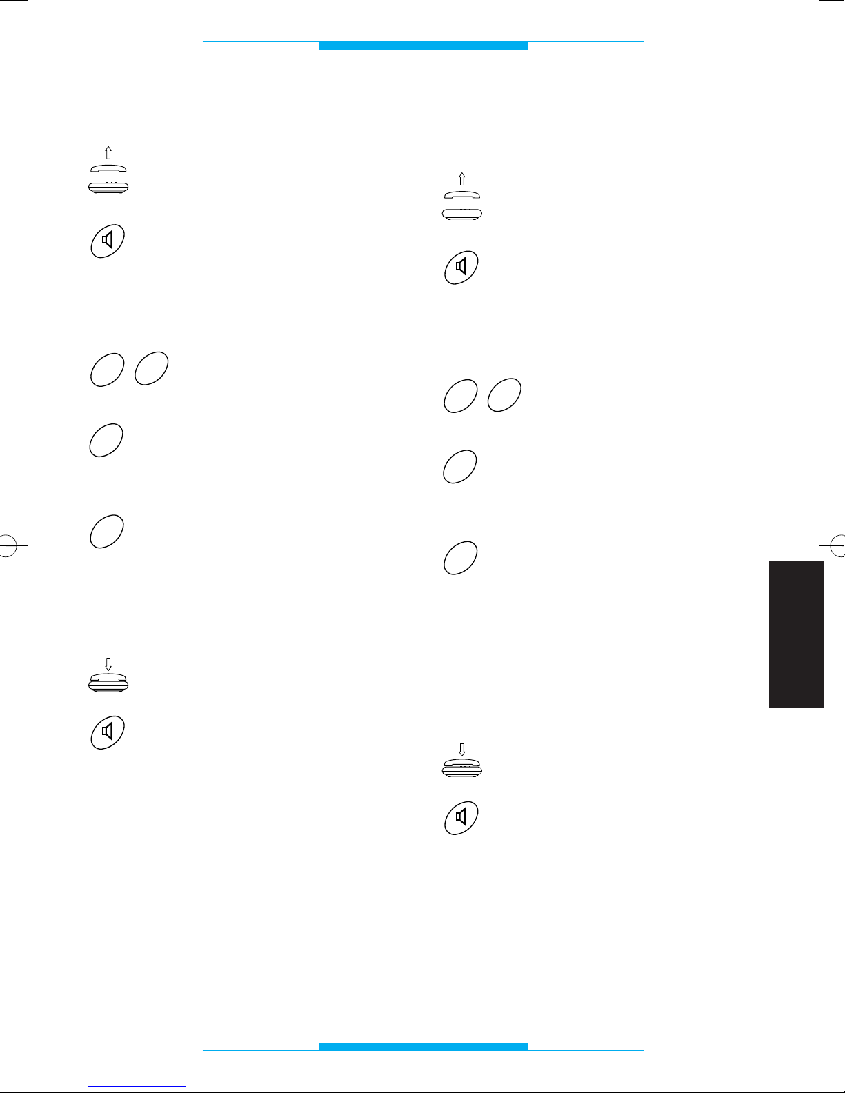
73
FRANÇAIS
PROGRAMMATION
Interception flash
Soulever le récepteur
ou bien
appuyer sur la touche vive-
voix.
Après cette opération, on doit entendre une
double tonalité invitant à la programmation.
Taper 63.
Taper 0 pour interception
flash exclu (connexion au
téléphone XT/200)
ou bien
1 pour interception flash
activée (connexion au téléphone DTMF générique).
Après cette opération, on doit entendre une
triple tonalité de confirmation.
Raccrocher
ou bien
appuyer sur la touche vivevoix.
1
0
3
6
Type de moniteur à
associer au téléphone
Soulever le récepteur
ou bien
appuyer sur la touche vive-
voix.
Après cette opération, on doit entendre une
double tonalité invitant à la programmation.
Taper 64.
Taper 0 lorsque vous utilisez
le moniteur XV/200 ou
XVC/200
ou bien
1 lorsque vous utilisez le
moniteur IMT/200 ou
IMTC/200.
NOTE. Dans des installations avec postes
intérieurs mixtes, taper 1.
Après cette opération, on doit entendre une
triple tonalité de confirmation.
Raccrocher
ou bien
appuyer sur la touche vivevoix.
1
0
4
6
Page 76
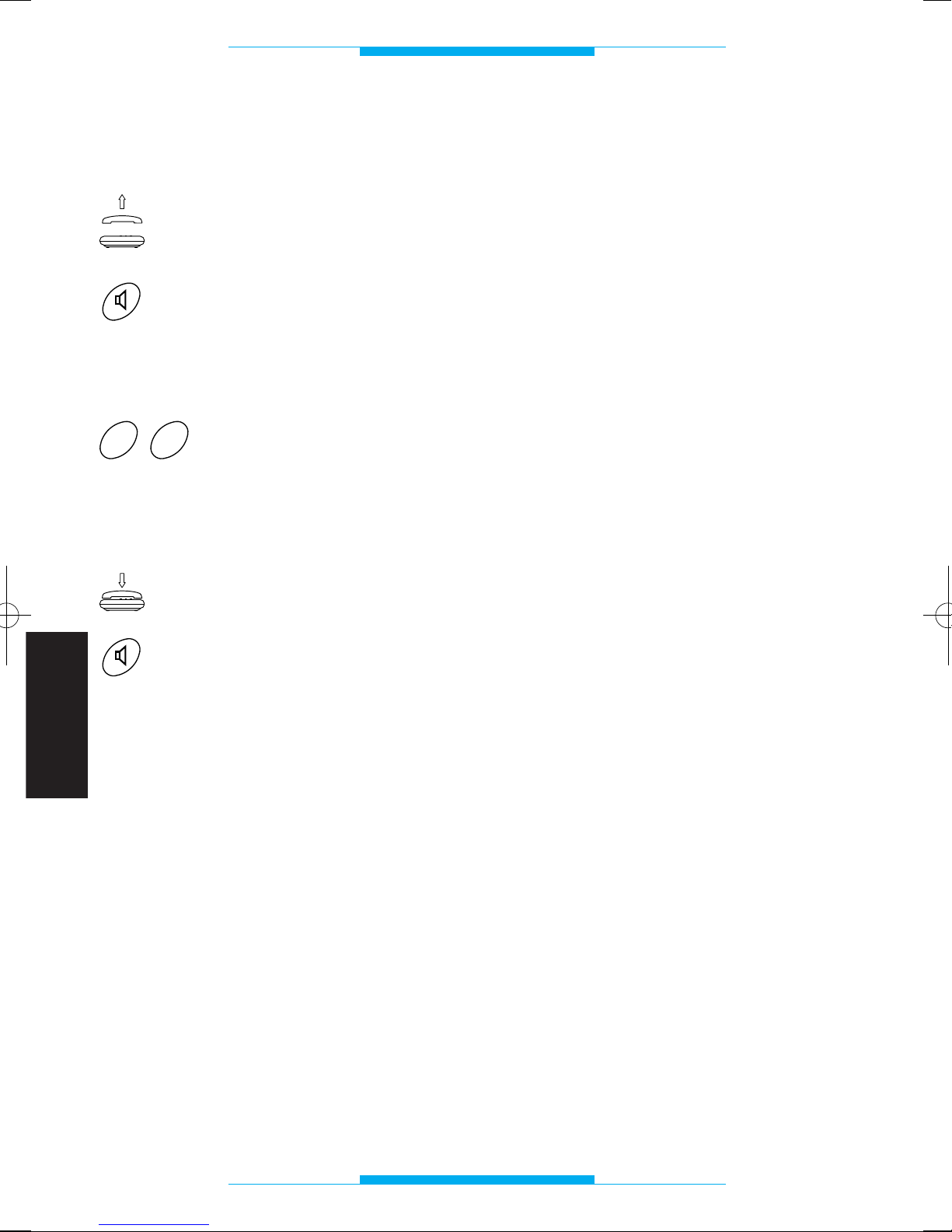
74
FRANÇAIS
PROGRAMMATION
Rétablissement de la
configuration de default
Soulever le récepteur
ou bien
appuyer sur la touche vive-
voix.
Après cette opération, on doit entendre une
double tonalité invitant à la programmation.
Taper 00.
Après cette opération, on doit entendre une
triple tonalité de confirmation.
Raccrocher
ou bien
appuyer sur la touche vivevoix.
0
0
Page 77
75
FRANÇAIS
CARACTERISTIQUES TECHNIQUES
• Alimentation: 230 Vca 50 Hz.
• Consommation: 6 VA maxi.
• Tension de sortie: 24 V.
• Tension d’appel: 50V eff./50 Hz.
• Long. maxi des câbles de connexion
pour chaque poste intérieur: 100 m
(câble téléphonique de 6/10).
• Nombre de postes intérieurs sur la même
ligne: 5 maxi.
• Possibilité de rétablir la protection électro-
nique.
• Déviation de fréquence: suivant les nor-
mes CCITT.
• Mise en service moniteur pour la durée
de la conversation.
• Durée maximum conversation portier
électronique: 99 s.
• Connexion pour minuteure: simple (type
OPEN COLLECTOR 24 Vcc, 50 mA).
• Connexion pour appel concierge.
• Durée temps flash (R) programmable.
• Durée temps d’enclenchement ouvre-
porte de 1 à 15 s.
• Connexion ligne urbaine même en absen-
ce d’alimentation secteur.
• Température de fonctionnement: de 0 °C
à +35 °C.
• Humidité relative: 90% sans condensa-
tion.
• Classe d’isolation II.
• Dimensions: module de 8 unités bas pour
rail DIN.
• Fréquence tonalités de signalisation: 375
Hz.
L’appareil est homologué suivant les normes
CTR 21 et satisfait à la norme EN 60950
relative à la sécurité électrique et à la directive 89/336/EEC modifiée par la directive
93/68/EEC relative à la compatibilité électromagnétique.
Approbation européenne délivrée par le
BZT-ETS CERTIFICATION GmbH
Page 78
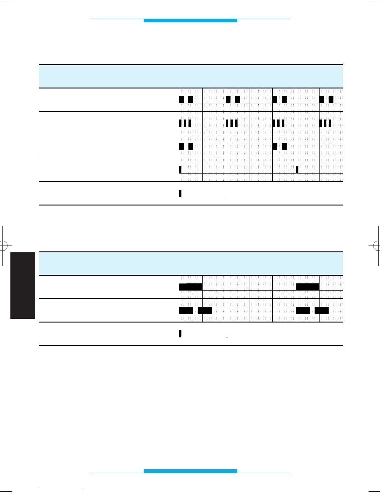
76
FRANÇAIS
TONALITES ET RYTHMES
FONCTION
TEMPS (secondes)
1234
5
60
FONCTION
TEMPS (secondes)
1
2
3
4
50
Programmation
Confirmation de fin de programmation
Attente
Avis
Portier électronique
Urbaine
6
= Pause= Note
= Pause= Note
Tonalités de signalisation
Rythmes d’appel
Page 79
77
FRANÇAIS
GLOSSAIRE
Combiné
Il permet de communiquer avec le poste
extérieur et de commander l’ouverture de la
porte.
Default
On entend avec ce terme toute opération
prévue sur l’appareil ou programmation
effectuée en usine par le fabricant.
Flash (R)
En appuyant sur cette touche sur le
téléphone relié, l’interface est prête à recevoir une commande (et non un numéro de
téléphone) effectuée avec le clavier.
Ligne urbaine
Connexion qui permet de communiquer
avec les abonnés de l’annuaire téléphonique.
Poste extérieur
Il permet au visiteur d’appeler la personne
intéressée et de converser.
S’il est doté de caméra, il transmet les images sur le moniteur installée dans la maison.
Téléphone
Appareil qui normalement permet de
téléphoner ou de recevoir une communication téléphonique sur la ligne urbaine. Avec
la centrale IT/200, le téléphone peut également être utilisé comme combiné.
Téléphone à décades
Téléphone à cadran: certains téléphones à
touches sont également à décades: un
téléphone est à décades si, lorsque l’on
compose un numéro, on entend dans le
récepteur les unités.
Téléphone multifréquence
Il est également appelé MF ou DTMF, c’est
le téléphone le plus moderne.
Un téléphone est multifréquence si morsque l’on compose un numéro, on entend
dans le récepteur des tonalités.
Portier vidéo
Outre les fonctions du combiné, il permet
de voir sur un écran le visiteur qui appelle
depuis le poste extérieur.
Page 80
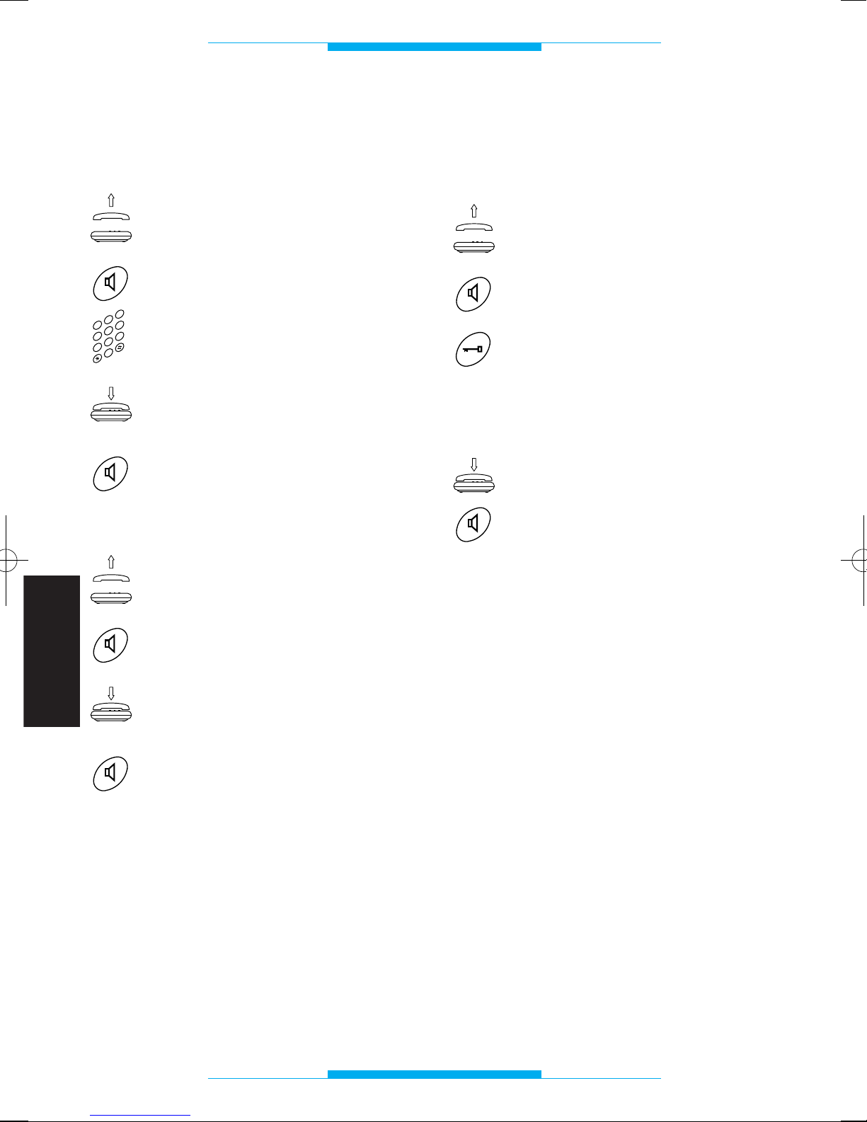
78
FRANÇAIS
FONCTIONS
Appel sur ligne urbaine
Il est possible d’appeler comme avec les
autres appareils.
Soulever le récepteur
ou bien
appuyer sur la touche vive-voix.
Composer sur le clavier le
numéro désiré.
En fin de conversation, raccrocher
ou bien
appuyer sur la touche vive-voix.
Réponse aux appels en arrivée
Soulever le récepteur
ou bien
appuyer sur la touche vive-voix.
En fin de conversation, raccrocher
ou bien
appuyer sur la touche vive-voix.
Le téléphone sonne avec des rythmes différents suivant que l’appel provienne d’une
ligne urbaine ou bien du poste extérieur.
Voir le chapitre TONALITES ET RYTHMES
de la sonnerie.
2
3
4
0
5
6
1
7
8
9
Réponse à un appel
provenant du poste extérieur
et ouverture de la porte
Soulever le récepteur
ou bien
appuyer sur la touche vive-voix.
Si vous désirez faire entrer le
visiteur, appuyer sur la touche
ouvre-porte (pour les téléphones
bpt. Pour d’autres téléphones,
consulter le tableau récapitulatif).
Raccrocher
ou bien
appuyer sur la touche vive-voix.
NOTE. Si l’interface est programmée avec
la fonction INTERCEPTION FLASH exclue,
avec un téléphone standard multifréquence, il n’est pas possible d’effectuer cette
commande si l’on est en communication
avec la ligne urbaine.
Page 81
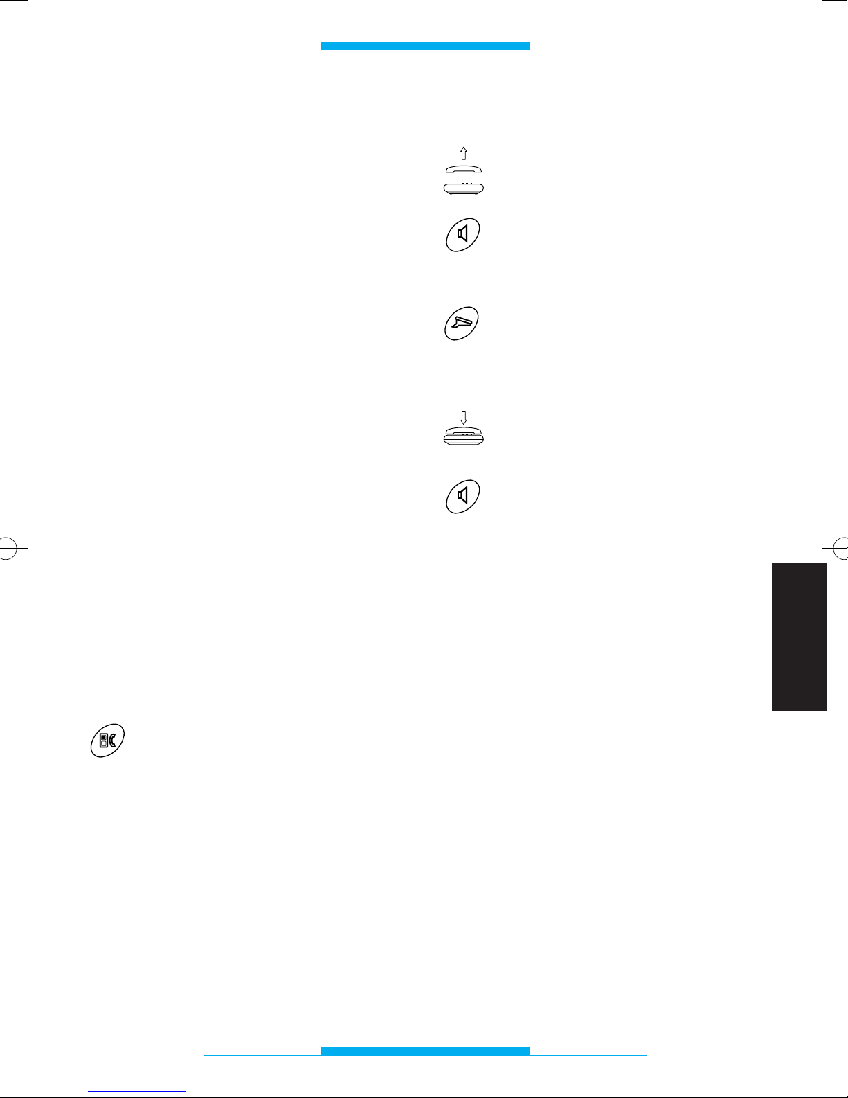
79
FRANÇAIS
FONCTIONS
Autointroduction
sur le poste extérieur
Il est possible d’activer le poste extérieur
pour lun des besoins suivants:
• surveiller l’extérieur avec portier audio et
vidéo (si le poste extérieur est doté de
caméra);
• échanger les postes extérieurs;
• enclencher l’ouvre-porte.
NOTE. L’autointroduction est possible uniquement si l’appareil est couplé au module
vidéo XV/200 et avec installation portier
vidéo libre.
Changement d’interlocuteur
Ce service permet à l’utilisateur en communication avec une ligne extérieure ou un
poste extérieur de répondre à un appel provenant de l’autre ligne en mettant en attente la communication en cours.
L’interlocuteur qui ne converse pas est
informé de cette condition moyennant une
tonalité acoustique.
NOTE. Pendant la conversation, l’utilisateur
est informé de l’appel en arrivée avec un
avis acoustique.
Pour changer d’interlocuteur pendant une
conversation:
Appuyer sur la touche de commutation combiné/téléphone
(pour les téléphones bpt. Pour
les autres types de téléphones,
consulter le tableau récapitulatif).
NOTE. Si l’interface est programmée avec
la fonction INTERCEPTION FLASH exclue,
avec un téléphone standard multifréquence, il n’est pas possible d’effectuer cette
commande si l’on est en communication
avec la ligne urbaine.
Appel concierge
Soulever le récepteur
ou bien
appuyer sur la touche vive-voix.
Attendre la tonalité invitant à la sélection.
Appuyer sur la touche appel
concierge (pour les téléphones
bpt. Pour les autres téléphones,
consulter le tableau récapitulatif).
En fin de conversation, raccrocher
ou bien
appuyer sur la touche vive-voix.
NOTE. Si l’interface est programmée avec
la fonction INTERCEPTION FLASH exclue,
avec un téléphone standard multifréquence, il n’est pas possible d’effectuer cette
commande si l’on est en communication
avec la ligne urbaine.
Page 82
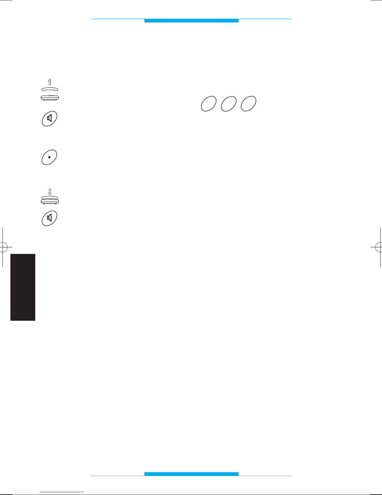
80
FRANÇAIS
FONCTIONS
Commande auxiliaire/minuterie
avec téléphone
Soulever le récepteur
ou bien
appuyer sur la touche vive-voix.
Attendre la tonalité invitant à la sélection.
Appuyer sur la touche auxiliaire
(pour les téléphones bpt. Pour
les autres téléphones, consulter
le tableau récapitulatif).
Raccrocher
ou bien
appuyer sur la touche vive-voix.
NOTE. Si l’interface est programmée avec
la fonction INTERCEPTION FLASH exclue,
avec un téléphone DTMF, il n’est pas possible d’effectuer cette commande si l’on est
en communication avec la ligne urbaine.
ATTENTION. Dans des installations avec
secret de conversation, cette commande
est disponible uniquement si le poste intérieur a été appelé depuis le poste extérieur.
Exclusion signal acoustique
avertissant
d’un appel en arrivée
Taper R83 avant de
composer le numéro de
téléphone.
Pendant tout le temps de la conversation,
le ton du signal acoustique est exclus.
Utiliser cette fonction pour effectuer un raccordement à un modem. Si l’on désire
obtenir l’exclusion en automatique, ajouter
la série de caractères !83, (voir la notice du
logiciel de la connexion téléphonique).
Accès aux services en DTMF
de la compagnie de téléphone
L’accès est toujours possible lorsque l’on a
configuré l’interface avec INTERCEPTION
FLASH exclue. Lorsqu’elle est configurée
avec INTERCEPTION FLASH enclenchée,
l’accès est possible uniquement en communication avec la ligne urbaine et en
absence d’appels depuis le poste extérieur
du portier électronique.
3
8
R
Page 83
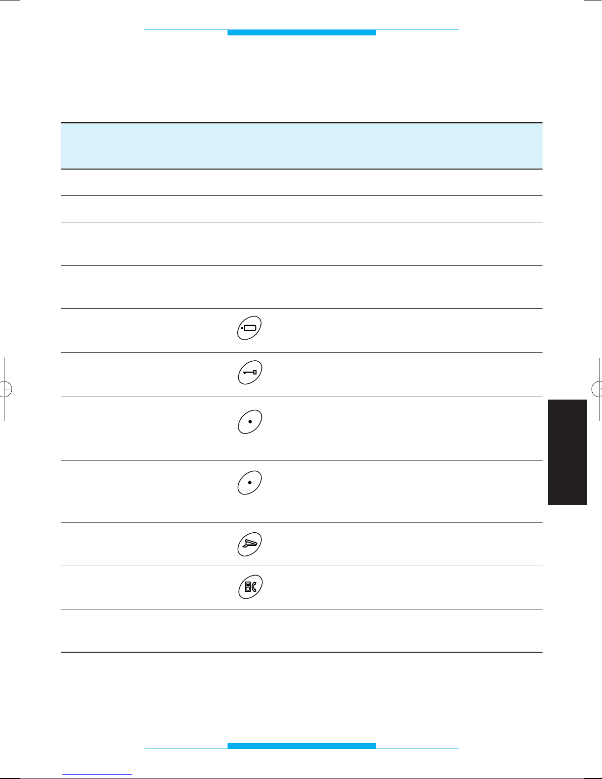
81
FRANÇAIS
FONCTIONS
TELEPHONE BPT TELEPHONE TELEPHONE
XT/200 MULTIFREQUENCE A DECADES
PROGRAMMATION oui oui impossible
APPEL URBAIN direct direct direct
RECEPTION APPELS oui oui oui
URBAINS/TELEPHONIQUES
ACCES AUX SERVICES oui oui impossible
TELECOM EN DTMF
AUTOINTRODUCTION (XV/200) R+86 impossible
OUVRE-PORTE R+85 impossible
AUXILIAIRE/MINUTERIE R+88 impossible
CENTRALISEE (sortie
disponible sur alimentation)
AUXILIAIRE/MINUTERIE R+88 impossible
SIMPLE (sortie
disponible sur IT/200) (
1
)
APPEL CONCIERGE R+87 impossible
CHANGEMENT R+80 impossible
INTERLOCUTEUR
(1) Il est également possible d’utiliser la sortie AUXILIAIRE/MINUTERIE SIMPLE dans des
installations avec MINUTERIE CENTRALISEE en mettant les dip-switch 4 et 5 sur OFF.
Fonctions possibles avec l’utilisation du téléphone bpt
et avec des téléphones standard
Page 84
82
FRANÇAIS
Page 85
83
ESPAÑOL
INDICE
Instrucciones para el instalador
Características generales . . . . . . . . . . . .84
Advertencias . . . . . . . . . . . . . . . . . . . . . .85
Instalación . . . . . . . . . . . . . . . . . . . . . . . .86
Conexiones . . . . . . . . . . . . . . . . . . . . . . .87
Puesta en marcha . . . . . . . . . . . . . . . . . .88
Programación . . . . . . . . . . . . . . . . . . . . .89
- Configuración por defecto . . . . . . . . . .89
- Entrada y salida de las
operaciones de programación . . . . . .89
- Modalidad secreto
de conversación . . . . . . . . . . . . . . . . .89
- Duración conversación
de portero electrónico . . . . . . . . . . . . .90
- Modalidad analógico o codificado . . .90
- Código IT/200 en formato
bloque/usuario y programación
en modo codificado . . . . . . . . . . . . . . .91
- Código IT/200 en formato
progresivo y programación
en modo codificado . . . . . . . . . . . . . . .91
- Duración mando
de control abrepuerta . . . . . . . . . . . . .92
- Modalidad reconocimiento flash . . . . .92
- Reconocimiento señal flash . . . . . . . . .93
- Tipo de monitor a combinar
con el teléfono . . . . . . . . . . . . . . . . . . .93
- Reactivación de la
configuración por defecto . . . . . . . . . .94
Características técnicas . . . . . . . . . . . . .95
Tonos y señales de llamada . . . . . . . . . .96
- Tonos de indicación . . . . . . . . . . . . . . .96
- Tonos de llamada . . . . . . . . . . . . . . . . .96
Instrucciones para el usuario
Glosario . . . . . . . . . . . . . . . . . . . . . . . . . .77
Funciones . . . . . . . . . . . . . . . . . . . . . . . .98
- Llamada en línea urbana . . . . . . . . . . .98
- Respuesta a las
llamadas entrantes . . . . . . . . . . . . . . . .98
- Respuesta a las llamadas
desde placa exterior
y apertura de la puerta . . . . . . . . . . . .98
- Autoactivación de la placa exterior . . .99
- Cambio interlocutor . . . . . . . . . . . . . . .99
- Llamada conserje . . . . . . . . . . . . . . . .99
- Mando de control auxiliar/
luz escalera desde el teléfono . . . . . .100
- Inhabilitación aviso acústico
de llamada en entrada . . . . . . . . . . . .100
- Acceso a los servicios en DTMF
de la compañia telefónica . . . . . . . . .100
- Funciones que se pueden obtener
al utilizar el teléfono bpt
y con los teléfonos estándar . . . . . . .101
Page 86
84
ESPAÑOL
CARACTERISTICAS GENERALES
El interfaz telefónico permite la conexión de
un aparato telefónico a la línea de videoportero o portero electrónico de la serie 200
y de la serie 100, esté o no codificado.
Permite la utilización del teléfono bpt y de
aparatos de teléfonos normales decádicos
o DTMF, inalámbricos, contestador automático, módem, PABX, etc.
El aparato también permite enviar llamadas
a una centralita de conserjería de tipo
analógico o digital y controlar los mandos
abrepuerta, luz escalera centralizada, etc.
El aparato realizado en formato DIN de 8
módulos, está compuesto de un circuito
impreso y por una tarjeta que contiene los
dip-switch para realizar la programación y
la selección del tipo de instalación.
Funciones básicas
• Acceso directo a la línea urbana.
• Conexión al sistema de videoportero
serie 200 con función de autoactivación
(si se combina con el módulo monitor).
• Conexión al sistema de videoportero
serie 100.
• Conexión al sistema de portero electróni-
co con o sin secreto de conversación.
• Secreto de conversación para equipos
BPT.
• Codificador/decodificador de llamada
integrado.
• Comunicación telefónica aunque la red
no suministre alimentación.
• Tono de llamada diferente desde la placa
exterior/línea telefónica.
• Mando de control abrepuerta.
• Mando de control auxiliar/luz escalera.
• Llamada conserje.
• Llamada en espera (urbana/de portero
electrónico.
• Protección línea telefónica frente a sobre-
cargas.
• Programación del aparato desde el teléfo-
no.
• Alimentación por red eléctrica.
Page 87
85
ESPAÑOL
ADVERTENCIAS
Leer atentamente las advertencias incluidas
en este manual ya que proporcionan indicaciones importantes con respecto a la seguridad de utilización, instalación y mantenimiento.
Después de haber desembalado el aparato, comprobar que está en perfectas condiciones.
Los elementos del embalaje (bolsas de plástico, espuma de poliestireno, etc.) no se
deben dejar al alcance de los niños ya que
representan potenciales fuentes de peligro.
La eliminación de los embalajes se debe
realizar de acuerdo con las normas vigentes.
La ejecución de la instalación tiene que
respetar las normas de seguridad en vigor.
No instalar los cables telefónicos por el
mismo recorrido que los cables eléctricos.
Instalar la centralita en ambientes sin polvo,
lejos de equipos que puedan generar perturbaciones eléctricas de alta frecuencia
como: soldadores, motores eléctricos, hornos microondas, acondicionadores de aire,
etc.
Se aconseja instalar a al entrada del alimentador un interruptor de características y
protección adecuado.
Antes de conectar el aparato, habrá que
comprobar que los datos de la placa corresponden a los de la red de distribución.
Este aparato se tiene que utilizar únicamente para el objetivo para el que ha sido
diseñado; cualquier otro tipo de uso se considerará impropio y peligroso.
El fabricante no puede ser considerado
responsable por posibles daños derivados
de usos impropios, erróneos o irracionales.
Antes de realizar cualquier operación de
limpieza o de mantenimiento, abrir el interruptor de la instalación para desconectar
el aparato de la red de alimentación eléctrica.
En caso de avería y/o mal funcionamiento
del aparato, habrá que desconectarlo de la
alimentación eléctrica y no manipularlo.
Si es necesario realizar alguna reparación,
habrá que dirigirse únicamente a un centro
de asistencia técnica autorizado por el
fabricante.
Si no se respetan estas advertencias, se
compromete gravemente la seguridad del
aparato.
El instalador tendrá que asegurarse de que
la información dirigida al usuario, donde
esté prevista, se entregue junto a los aparatos.
Todos los aparatos que forman la instalación se tienen que utilizar únicamente para
el objetivo para el que han sido diseñados.
Page 88
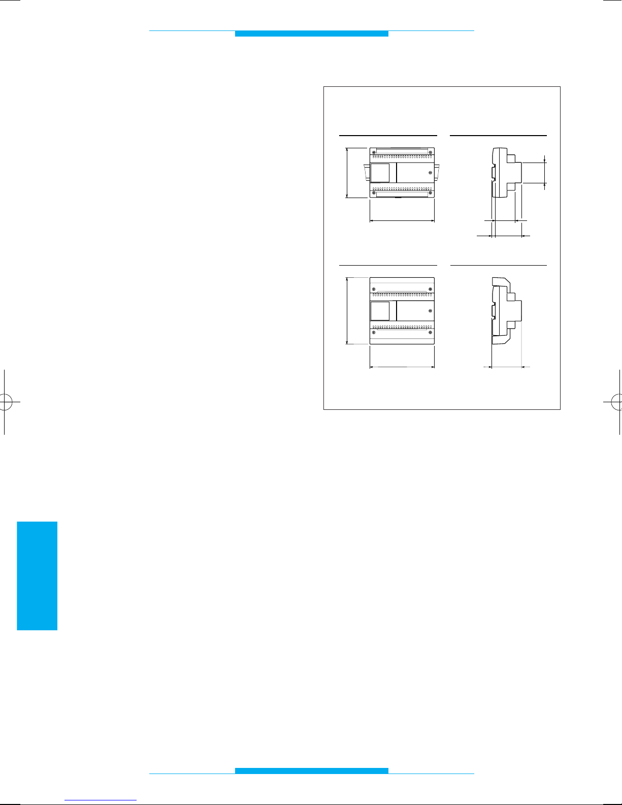
86
ESPAÑOL
INSTALACION
El interfaz se presenta en un módulo bajo
de 8 unidades y se puede instalar sin protege bornes en cajas dotadas de guía DIN
(EN 50022).
Por lo que respecta a las dimensiones
véase la fig. 1A.
También se puede instalar en la pared, con
protege bornes, utilizando la guía DIN que
se entrega junto al aparato.
Por lo que respecta a las dimensiones
véase la fig. 1B.
43,5
45
7,5
57
140
106
A
B
64,5
140
145
Fig. 1
Page 89
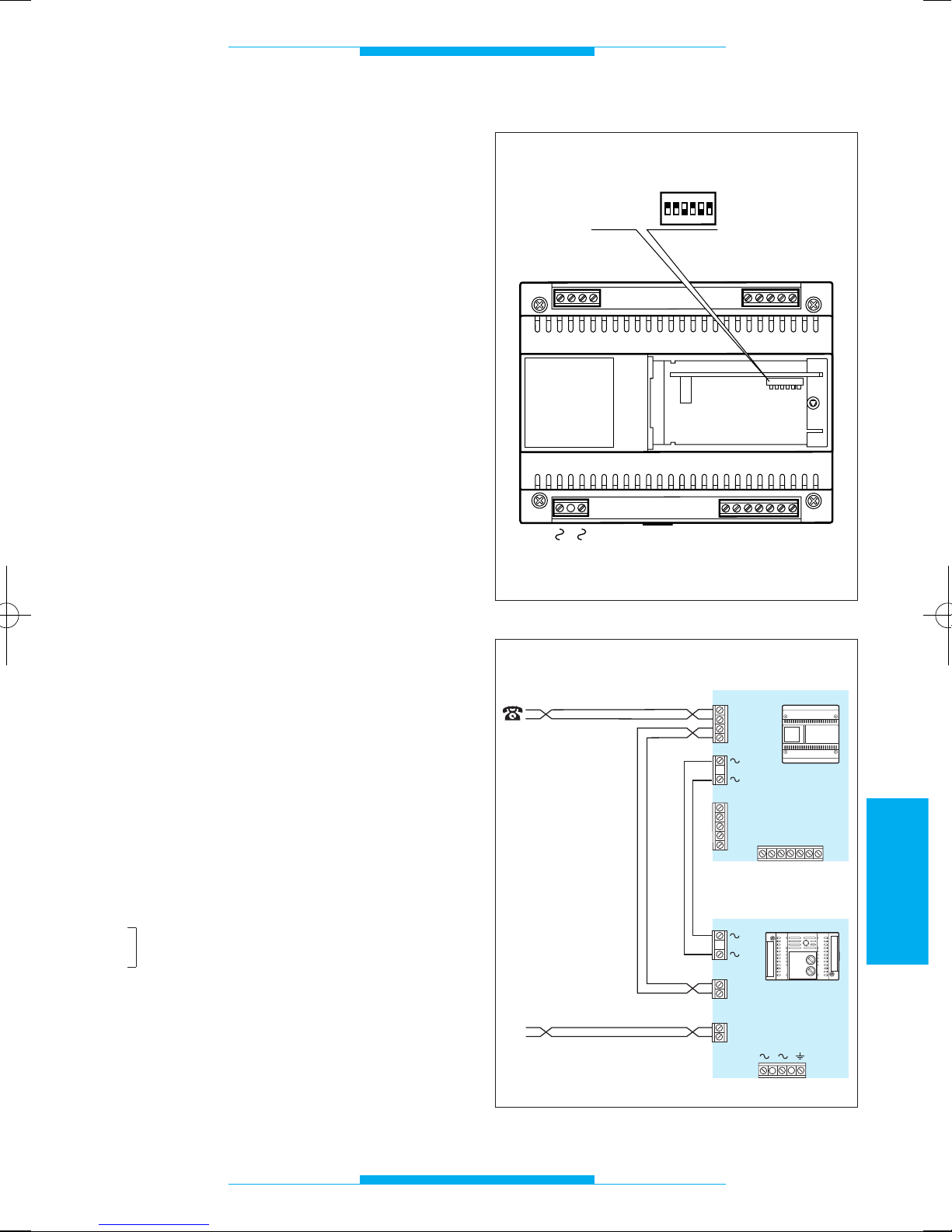
87
ESPAÑOL
CONEXIONES
Para acceder a las borneras extraer las
tapas protectoras. Se aconseja utilizar
cable telefónico de 6/10 para realizar la
conexión de los teléfonos.
Distancia máxima entre interfaz telefónico y
teléfono: 100 m.
NOTA. El aparato debe conectarse sólo son
líneas telefónicas analógicas, no con líneas
digitales ISDN.
Función
de los bornes
Bornera T (línea telefónica)
ae línea urbana
be línea urbana
au teléfono
bu teléfono
Bornera C (del alimentador)
5 masa
6 entrada alimentación monitor
7 llamada
8 audio desde la placa exterior
9 audio hacia la placa exterior
12 llamada conserjería
22 auxiliar/luz escalera
Bornera M (en el derivado interno)
5 masa
6 salida alimentación monitor
7 llamada
8 audio desde la placa exterior
9 audio hacia la placa exterior
Bornera A
~
red
~
CUIDADO. SE RECOMIENDA PROTEGER
LA LÍNEA TELEFÓNICA Y LA
ALIMENTACIÓN DE RED DE SOBRECARGAS DE TENSIÓN CON EL PROTECTOR
DE LÍNEA LP/MT.
A
C
5
6
7
8
9
12
T
ae
be
au
bu
M
22
SW1
5
6
7
8
9
ON
OFF
ON
1
2
3
4
56
Fig. 2
Fig. 3
TL
IT/200
T
bu
au
be
ae
A
M
5
6
7
8
9
LP/MT
M3
M4
au
bu
M2
ae
be
56789
C
M1
F2
F1
12 22
Page 90
88
ESPAÑOL
PREPARACION DIP-SWITCH
DIP-SWITCH PORTERO VIDEOPORTERO VIDEOPORTERO
ELECTRONICO SISTEMA 100 SISTEMA 200
SW1 ON ON ON
SW2 OFF OFF ON
SW3 ON OFF ON
SW4 ON OFF ON
SW5 OFF ON OFF
SW6 ON OFF ON
El puente SW1 se coloca en posición OFF sólo durante el procedimiento de PROGRAMACION.
PUESTA EN MARCHA
El interfaz permite la conexión a los siguientes tipos de equipos BPT:
- portero electrónico convencional
- portero electrónico con secreto de conversación
- videoportero sistema 100
- videoportero sistema 200
- llamada electrónica o codificada
Dispone de 6 dip-switch (fig. 2) a configurar
en función del tipo de equipo (fig. 3).
Además de la programación de los dipswitch, en el aparato también se tiene que
programar el tipo de instalación del equipo.
Para realizar esta operación se utiliza el
teléfono (véase el capítulo PROGRAMACION).
El aparato es compatible con las instalaciones en equipos de videoportero sistema
200.
ATENCIÓN. Para las instalaciones de portero electrónico sin secreto de conversación
es preciso programar el aparato según la
modalidad indicada en la página 89.
Fig. 3
Page 91
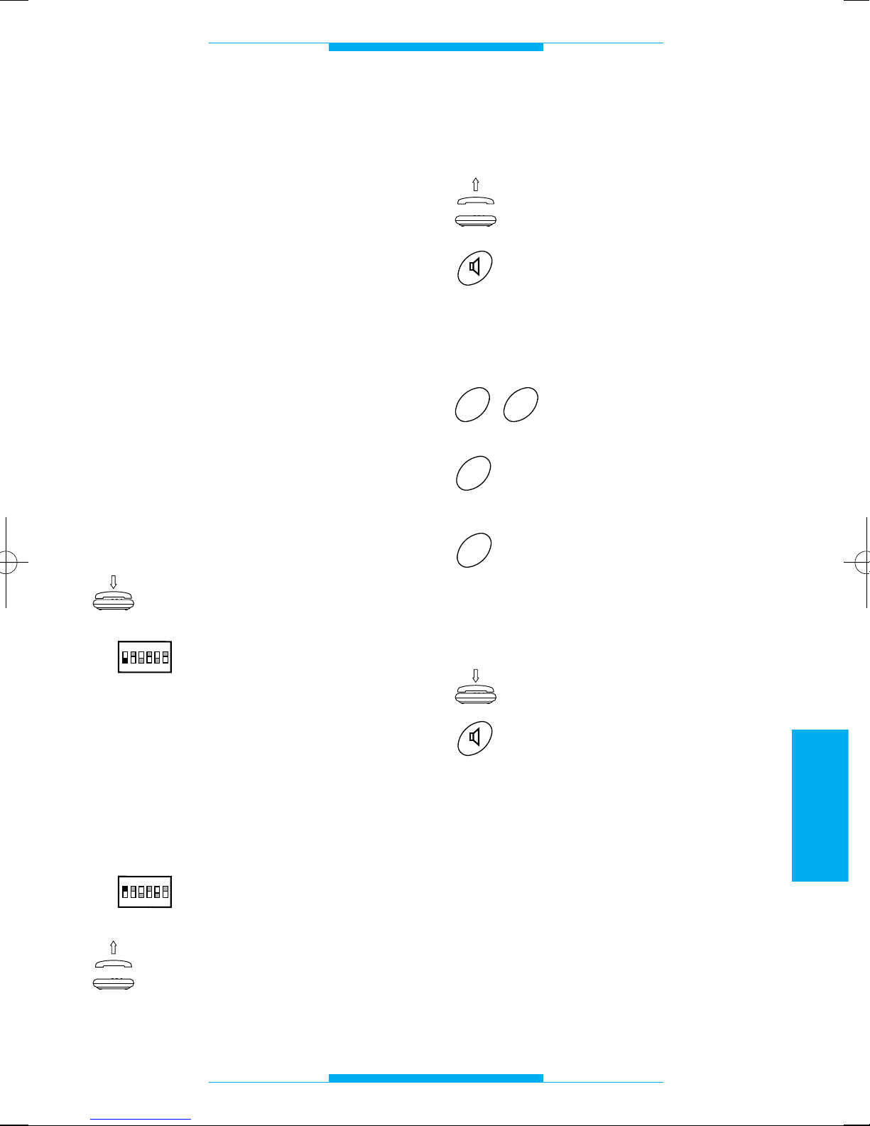
89
ESPAÑOL
PROGRAMACION
Configuración por defecto
• Modalidad reconocimiento flash: estándar
homologado.
• Secreto de conversación: activo.
• Duración conversación portero electróni-
co: 60 s.
• Duración mando de control abrepuerta: 1 s.
• Modalidad: equipos con llamada analó-
gica.
• Código programado para conexiones en
equipos con llamada codificada: 80155.
• Reconocimiento señal flash: deshabilitada.
• Tipo de monitor combinado con el teléfo-
no: XV/200.
Entrada y salida de las
operaciones de programación
Para entrar en modo programación
desde el teléfono conectado al interfaz
teléfonico:
Asegurarse de que el auricular está colgado.
Colocar el dip-switch 1 en
posición OFF.
Durante esta fase se puede ejecutar una o
varias operaciones de programación consecutivas.
El tecleo de los códigos de programación
debe ser efectuado durante la pausa del
tono de programación.
Para salir de la fase de programación:
Colocar el dip-switch 1 en
posición ON.
Cuando se active el teléfono, una vez finalizado el
procedimiento, se tiene que
oír el tono de línea telefónica libre.
ON
OFF
ON
1
2
3
4
56
ON
OFF
ON
1
2
3
4
56
Modalidad secreto
de conversación
Descolgar el auricular
o
pulsar la tecla manos libres.
Después de esta operación se tendrá que
oír un tono doble como invitación a realizar
la programación.
Marcar 29.
Marcar 0 para la modalidad
de equipo sin secreto
o
1 para la modalidad de
equipo con secreto.
Al terminar se oirá un tono triple de confirmación.
Colgar el auricular
o
pulsar la tecla manos libres.
1
0
9
2
Page 92
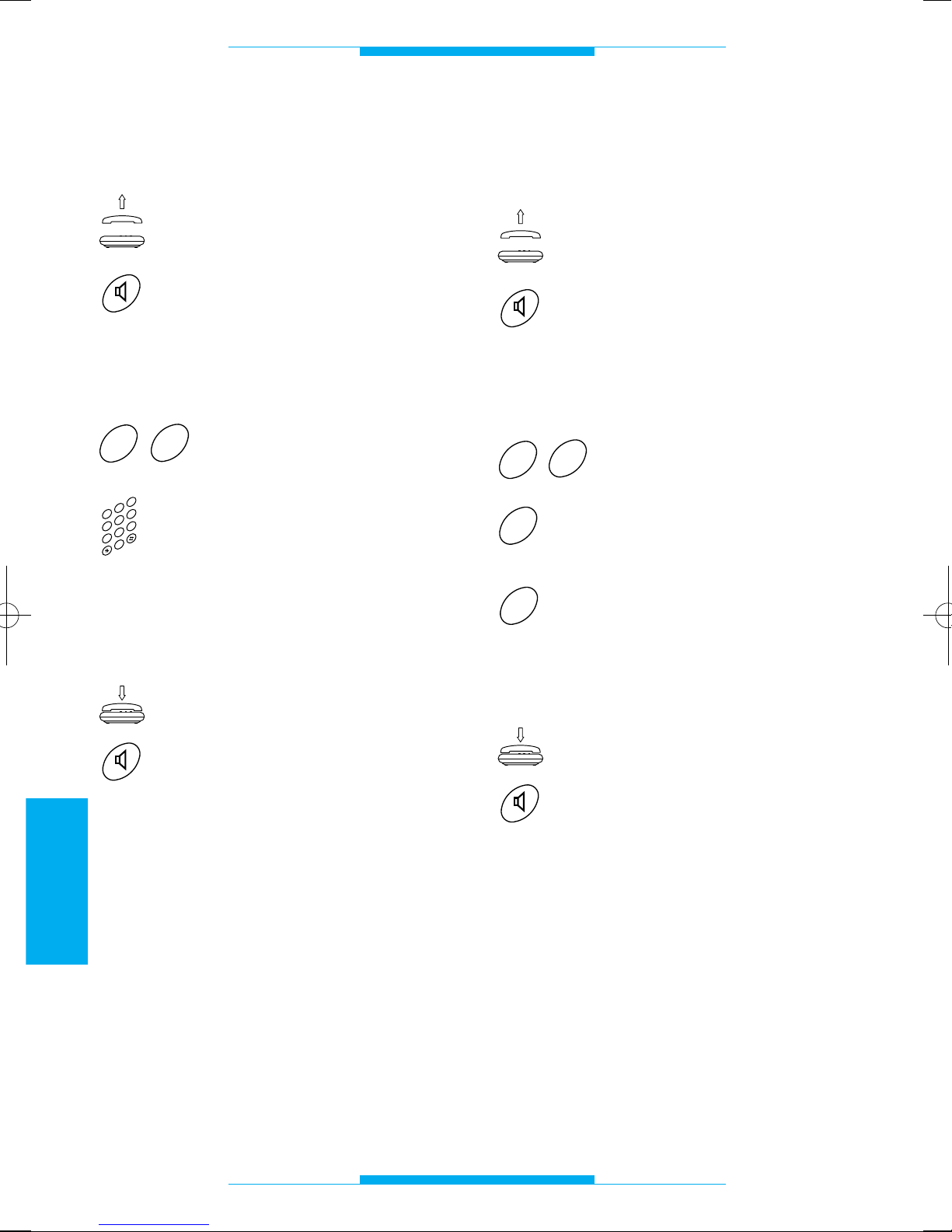
90
ESPAÑOL
PROGRAMACION
Duración conversación
de portero electrónico
Descolgar el auricular
o
pulsar la tecla manos libres.
Después de esta operación se tendrá que
oír un tono doble como invitación a realizar
la programación.
Marcar 27.
Teclear la duración de la
conversación (de 10 a 99
segundos). Ej.: 20 para 20
segundos.
Al terminar se oirá un tono triple de confirmación.
Colgar el auricular
o
pulsar la tecla manos libres.
NOTA. El tiempo se puede variar únicamente en los equipos de portero electrónico sin secreto de conversación (ej. con
A/200R).
2
3
4
0
5
6
1
7
8
9
7
2
Modalidad analógico o codificado
(véanse instrucciones de las placas exteriores
digitales)
Descolgar el auricular
o
pulsar la tecla manos libres.
Después de esta operación se tendrá que
oír un tono doble como invitación a realizar
la programación.
Marcar 62.
Marcar 0 para la modalidad
de equipo analógico (
1
)
o
1 para la modalidad de
equipo codificado.
Al terminar se oirá un tono triple de confirmación.
Colgar el auricular
o
pulsar la tecla manos libres.
(
1
)
Este tipo de programación sólo es necesaria si se desea configurar de nuevo la
interfaz anteriormente programada con
códigos digitales.
1
0
2
6
Page 93
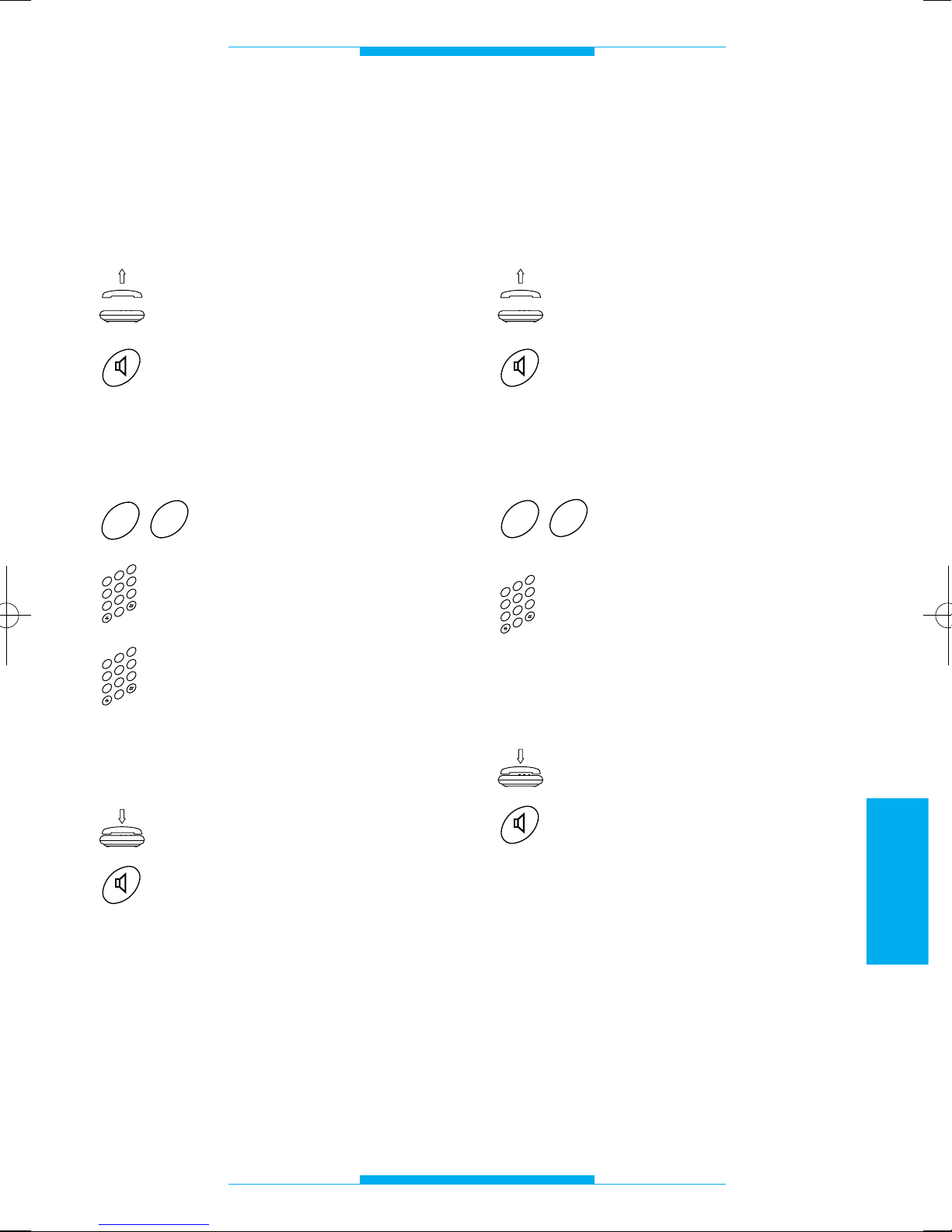
91
ESPAÑOL
PROGRAMACION
Código IT/200 en formato
bloque/usuario y programación
en modo codificado
(véanse instrucciones de las placas exteriores
digitales)
Descolgar el auricular
o
pulsar la tecla manos libres.
Después de esta operación se tendrá que
oír un tono doble como invitación a realizar
la programación.
Marcar 60.
Teclear el código de bloque
(de 00 a 80), ej. 39.
Teclear el código de usuario
(de 000 a 161), ej. 052.
Al terminar se oirá un tono triple de confirmación.
Colgar el auricular
o
pulsar la tecla manos libres.
2
3
4
0
5
6
1
7
8
9
2
3
4
0
5
6
1
7
8
9
0
6
Código IT/200 en formato
progresivo y programación
en modo codificado
(véanse instrucciones de las placas exteriores
digitales)
Descolgar el auricular
o
pulsar la tecla manos libres.
Después de esta operación se tendrá que
oír un tono doble como invitación a realizar
la programación.
Marcar 61.
Teclear el código de usuario
(de 00000 a 13121), ej.
01523.
Al terminar se oirá un tono triple de confirmación.
Colgar el auricular
o
pulsar la tecla manos libres.
2
3
4
0
5
6
1
7
8
9
1
6
Page 94
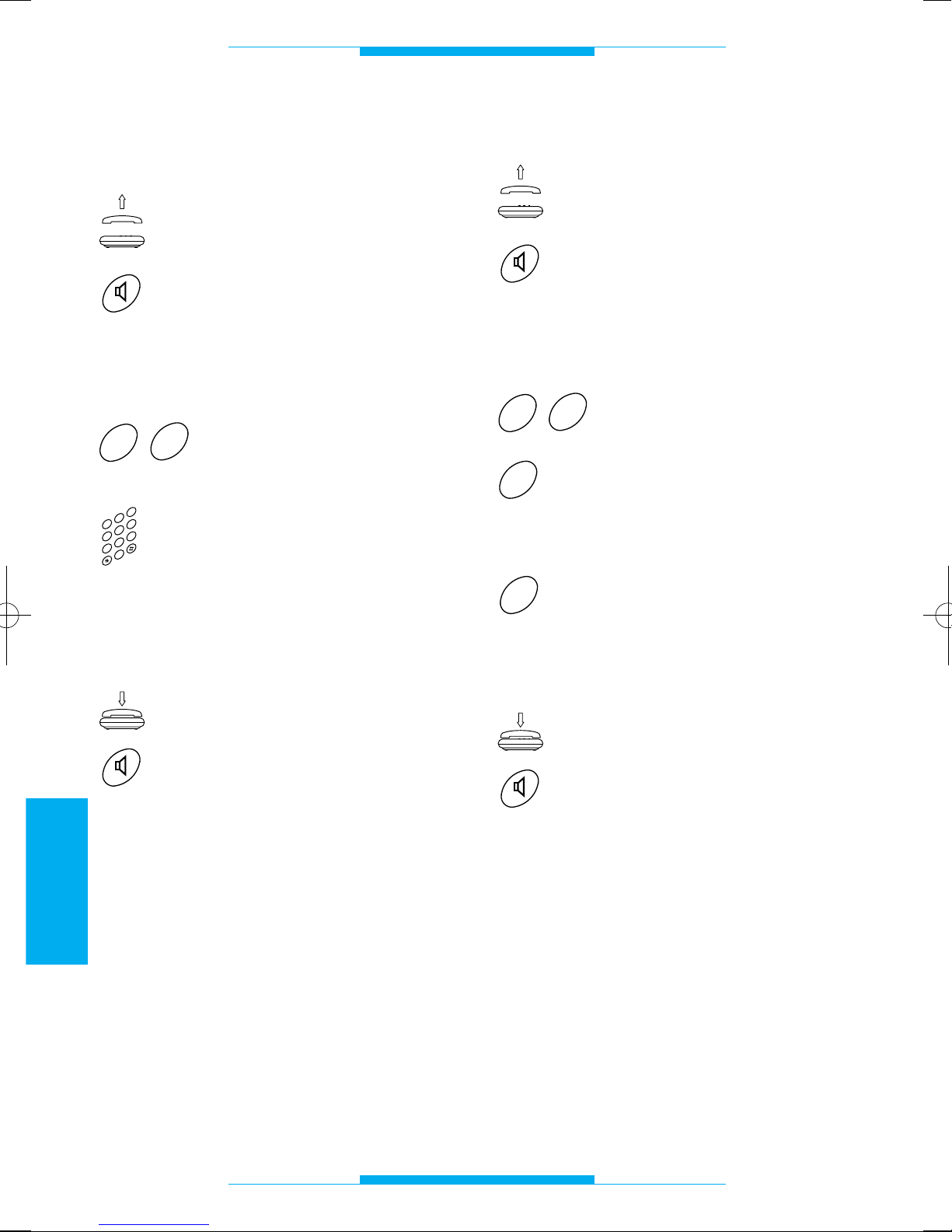
92
ESPAÑOL
PROGRAMACION
Duración mando
de control abrepuerta
Descolgar el auricular
o
pulsar la tecla manos libres.
Después de esta operación se tendrá que
oír un tono doble como invitación a realizar
la programación.
Marcar 28.
Teclear la duración del
mando de control abrepuerta (de 01 a 15 segundos).
Ej.: 06 para 6 segundos.
Al terminar se oirá un tono triple de confirmación.
Colgar el auricular
o
pulsar la tecla manos libres.
NOTA. Se puede utilizar esta función con
alimentadores que no tengan un temporizador centralizado (ej. A/200R o VA/100.
01
programado con mando de cierre manual).
2
3
4
0
5
6
1
7
8
9
8
2
Modalidad reconocimiento flash
Descolgar el auricular
o
pulsar la tecla manos libres.
Después de esta operación se tendrá que
oír un tono doble como invitación a realizar
la programación.
Marcar 20.
Marcar 0 para el reconocimiento estándar homologado flash
o
1 para el reconocimiento
flash prolongado.
Al terminar se oirá un tono triple de confirmación.
Colgar el auricular
o
pulsar la tecla manos libres.
1
0
0
2
Page 95
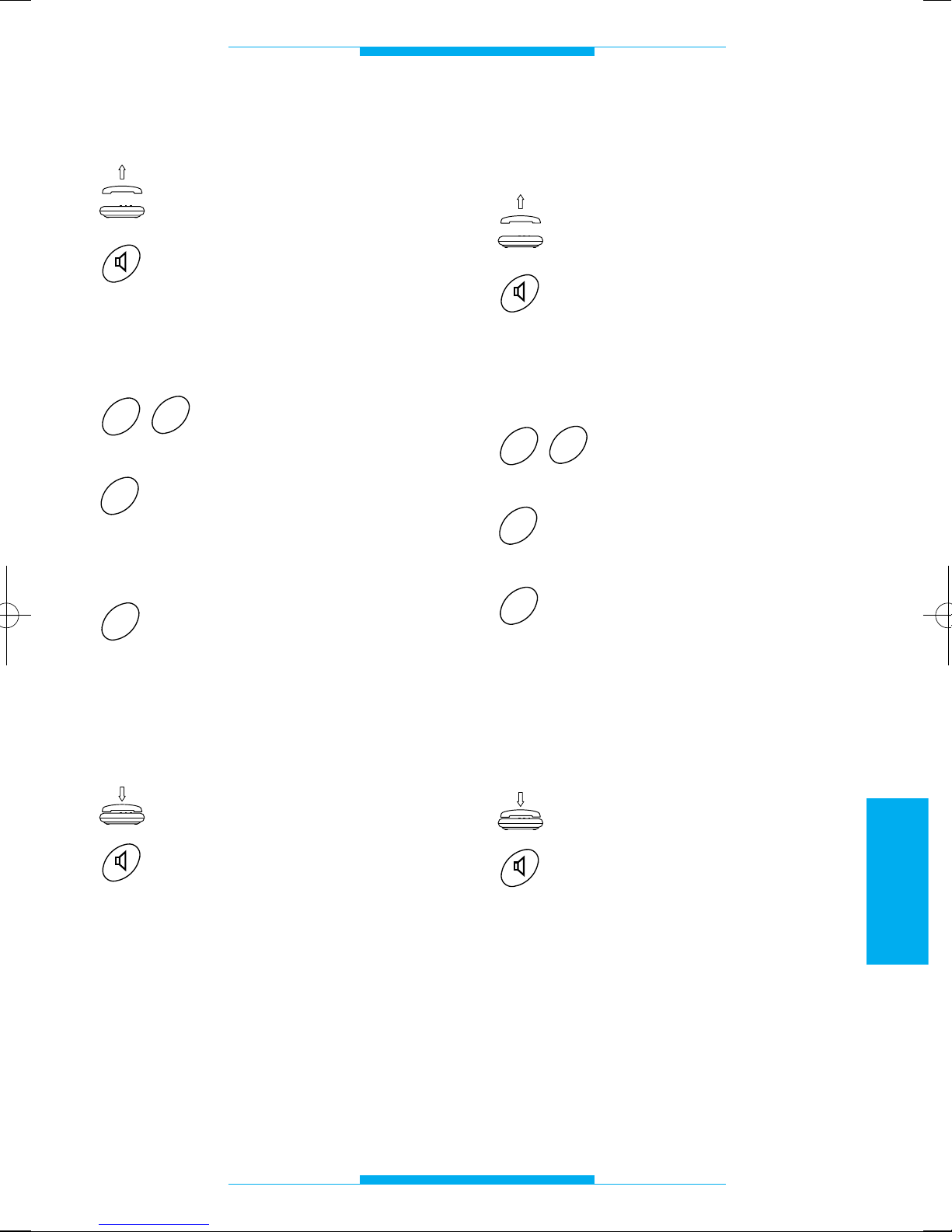
93
ESPAÑOL
PROGRAMACION
Reconocimiento señal flash
Descolgar el auricular
o
pulsar la tecla manos libres.
Después de esta operación se tendrá que
oír un tono doble como invitación a realizar
la programación.
Marcar 63.
Marcar 0 para deshabilitar el
reconocimiento de la señal
flash (conexión al teléfono
XT/200)
o
1 para habilitar el reconoci-
miento de la señal flash
(conexión al teléfono DTMF
genérico).
Al terminar se oirá un tono triple de confirmación.
Colgar el auricular
o
pulsar la tecla manos libres.
1
0
3
6
Tipo de monitor a combinar
con el teléfono
Descolgar el auricular
o
pulsar la tecla manos libres.
Después de esta operación se tendrá que
oír un tono doble como invitación a realizar
la programación.
Marcar 64.
Marcar 0cuando se utiliza el
monitor XV/200 o XVC/200
o
1 cuando se utiliza el moni-
tor IMT/200 o IMTC/200.
NOTA. En instalaciones con derivados
internos mixtos marcar 1.
Al terminar se oirá un tono triple de confirmación.
Colgar el auricular
o
pulsar la tecla manos libres.
1
0
4
6
Page 96
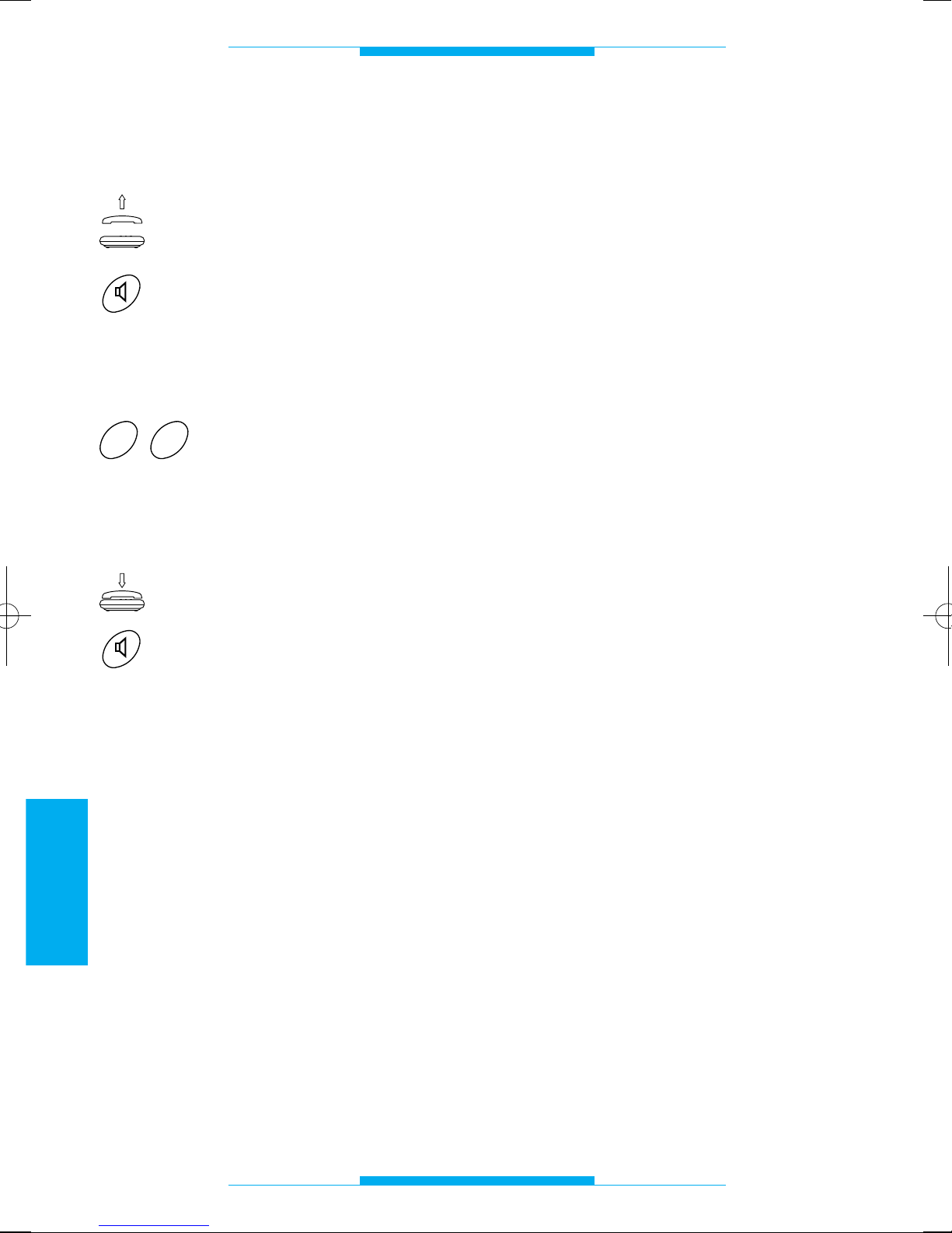
94
ESPAÑOL
PROGRAMACION
Reactivación de la
configuración por defecto
Descolgar el auricular
o
pulsar la tecla manos libres.
Después de esta operación se tendrá que
oír un tono doble como invitación a realizar
la programación.
Marcar 00.
Al terminar se oirá un tono triple de confirmación.
Colgar el auricular
o
pulsar la tecla manos libres.
0
0
Page 97
95
ESPAÑOL
CARACTERISTICAS TECNICAS
• Alimentación: 230 Vca - 50 Hz.
• Consumo: 6 VA máx.
• Tensión de salida: 24 V.
• Tensión de llamada: 50 V ef./50 Hz.
• Longitud máx. de los cables de conexión
de cada interno: 100 m (cable telefónico
de 6/10).
• Cantidad derivados en la misma línea: 5
máx.
• Protección electrónica reactivable.
• Desviación de frecuencia: según las nor-
mas CCITT.
• Habilitación monitor durante la conversa-
ción.
• Duración máxima conversación de porte-
ro electrónico: 99 s.
• Conexión para luz escaleras individual
(tipo OPEN COLLECTOR 24 Vcc, 50 mA).
• Conexión para llamada conserje.
• Duración tiempo flash (R) programable.
• Duración tiempo de activación abrepuer-
ta de 1 a 15 s.
• Conexión a la línea urbana incluso cuan-
do falta alimentación.
• Temperatura de funcionamiento: de 0 °C
a +35 °C.
• Humedad relativa: 90% sin condensa-
ción.
• Clase de aislamiento II.
• Dimensiones: módulo de 8 unidades bajo
para guía DIN.
• Frecuencia tonos de indicación: 375 Hz.
El aparato está homologado según las normas CTR 21 y cumple con la norma EN
60950, relativa a la seguridad eléctrica y con
la directiva 89/336/EEC modificada por la
93/68/EEC, relativas a la compatibilidad
electromagnética.
Aprobación europea expedida por
BZT-ETS CERTIFICATION GmbH
Page 98
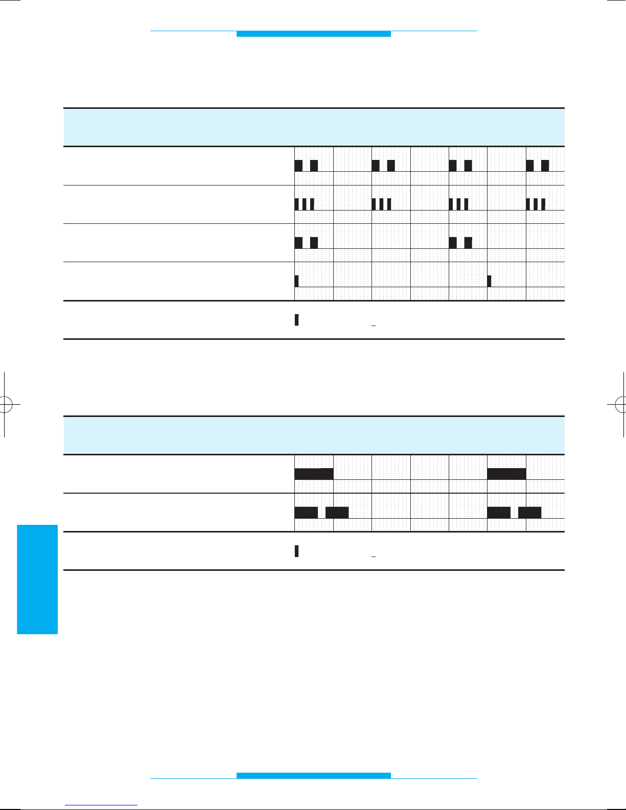
96
ESPAÑOL
TONOS Y SEÑALES DE LLAMADA
Tonos de indicación
Tonos de llamada
FUNCION
Programación
Confirmación de final de programación
Espera
Aviso
TIEMPO (segundos)
1234
= Pausa= Nota
5
60
FUNCION
Urbana
Portero electrónico
TIEMPO (segundos)
1
2
= Pausa= Nota
3
4
50
6
Page 99
97
ESPAÑOL
GLOSARIO
Teléfono
Permite la comunicación con la placa exterior y además puede controlar la apertura
de la puerta.
Por defecto
Con estas palabras se define la programación establecida por el fabricante.
Flash (R)
Si se pulsa esta tecla en el teléfono multifunción conectado, se prepara el interfaz
para recibir un mando de control (no un
número telefónico) del teclado.
Línea urbana
Conexión que permite la comunicación con
los usuarios de la red telefónica conmutada.
Placa exterior
Permite que el visitante pueda efectuar una
llamada al usuario y pueda conversar.
Si dispone de cámara transmitirá la imagen
al videoportero de casa.
Teléfono multifunción
Aparato que normalmente permite realizar y
recibir llamadas de la línea telefónica; con
la centralita IT/200 el teléfono multifunción
también se puede utilizar como portero
electrónico.
Teléfono multifunción decádico
Teléfono multifución de disco con dial de
diez números; algunos teléfonos con teclado también son decádicos: el teléfono es
decádico si, cuando se marca un número,
se oyen los impulsos de los pasos.
Teléfono multifunción
multifrecuencia
También se llama MF o DTMF, es el teléfono
multifunción más moderno.
Un teléfono multifunción es multifrecuencia
si, cuando se marca un número, en el auricular se oyen los tonos.
Videoportero
Además de las funciones del portero electrónico normal, dispone de una pantalla
donde aparece el visitante que se encuentra en la placa exterior.
Page 100
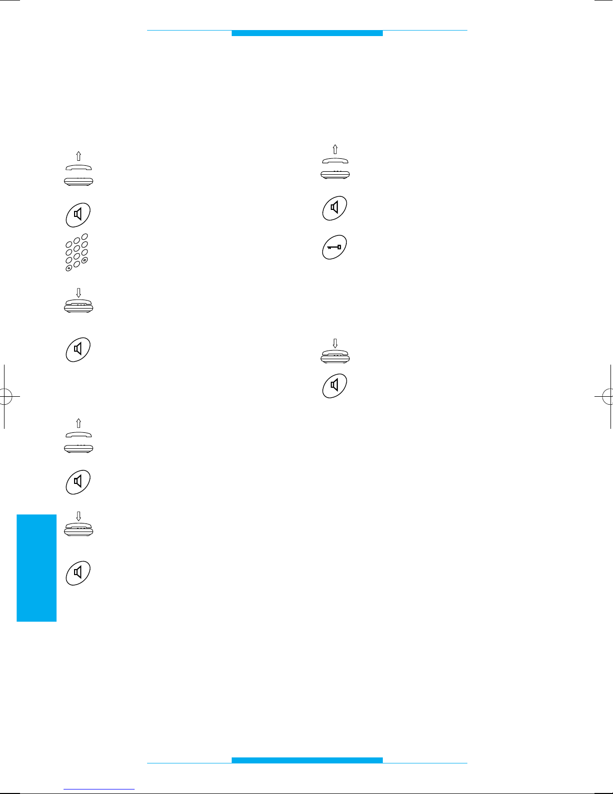
98
ESPAÑOL
FUNCIONES
Llamada en línea urbana
Se puede realizar una llamada de la manera habitual, como con cualquier otro aparato telefónico.
Descolgar el auricular
o
pulsar la tecla manos libres.
Marcar en el teclado el número
deseado.
Una vez haya finalizado la conversación, colgar el auricular
o
pulsar la tecla manos libres.
Respuesta a las llamadas
entrantes
Descolgar el auricular
o
pulsar la tecla manos libres.
Una vez haya finalizado la conversación, colgar el auricular
o
pulsar la tecla manos libres.
El teléfono multifunción suena con un tono
diferente dependiendo si la llamada procede se una línea urbana o de la placa exterior.
Véase el capítulo TONOS Y SEÑALES DE
LLAMADA.
2
3
4
0
5
6
1
7
8
9
Respuesta a las llamadas
desde la placa exterior
y apertura de la puerta
Descolgar el auricular
o
pulsar la tecla manos libres.
Si se desea hacer entrar a quien
ha llamado, pulsar la tecla abrepuerta (en teléfonos multifunción bpt, si se utilizan otros
teléfonos multifunción habrá
que consultar la tabla correspondiente).
Colgar el auricular
o
pulsar la tecla manos libres.
NOTA. Si el interfaz se ha programado con
la función RECONOCIMIENTO SEÑAL
FLASH deshabilitada, no se podrá ejecutar
el mando de control cuando se esté en
comunicación con la línea urbana si se trata
de un teléfono multifunción estándar multifrecuencia.
 Loading...