

Page 1
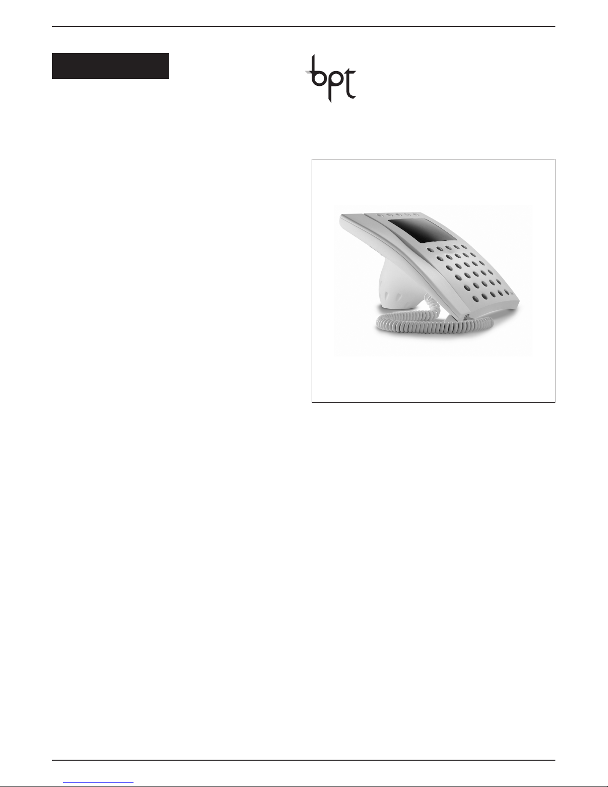
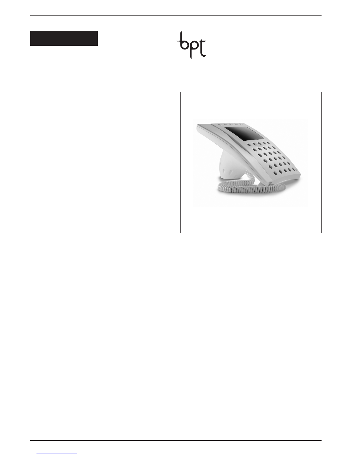
PORTER SWITCHBOARD
IPD/300LR US
R 5
INSTRUCTIONS MANUAL
02.2009/24074223
ENGLISH
B
PT S.p.A.
Via Cornia, 1
3
3079 Sesto al Reghena-PN-Italy
i
[email protected] – www.bpt.it
Page 2
2
CONTENTS
DESCRIPTION Page
PORTER SWITCHBOARD IPD/300LR . . . . . . . . . . . . . . . . . . . . . . 3
Standard functions . . . . . . . . . . . . . . . . . . . . . . . . . . . . . . . . . . . . . .3
Function of each terminal of socket VPM/240U . . . . . . . . . . . . . . . .3
S
pecifications . . . . . . . . . . . . . . . . . . . . . . . . . . . . . . . . . . . . . . . . . .3
Keypad functions . . . . . . . . . . . . . . . . . . . . . . . . . . . . . . . . . . . . . . .5
Controls . . . . . . . . . . . . . . . . . . . . . . . . . . . . . . . . . . . . . . . . . . . . . . .5
ACCESS TO PROGRAMMING MENU . . . . . . . . . . . . . . . . . . . . . . .6
Programming menu functions . . . . . . . . . . . . . . . . . . . . . . . . . . . . . .6
Menu language option . . . . . . . . . . . . . . . . . . . . . . . . . . . . . . . . . . .6
R
ing volume . . . . . . . . . . . . . . . . . . . . . . . . . . . . . . . . . . . . . . . . . . .6
Users management . . . . . . . . . . . . . . . . . . . . . . . . . . . . . . . . . . . . . .7
C
all filter . . . . . . . . . . . . . . . . . . . . . . . . . . . . . . . . . . . . . . . . . . . . . .8
Call divert . . . . . . . . . . . . . . . . . . . . . . . . . . . . . . . . . . . . . . . . . . . . .8
Entry panels selection . . . . . . . . . . . . . . . . . . . . . . . . . . . . . . . . . . . .8
Setup access code . . . . . . . . . . . . . . . . . . . . . . . . . . . . . . . . . . . . . .9
Set clock . . . . . . . . . . . . . . . . . . . . . . . . . . . . . . . . . . . . . . . . . . . . . .9
Call output mode . . . . . . . . . . . . . . . . . . . . . . . . . . . . . . . . . . . . . . . .9
Stand-by time
. . . . . . . . . . . . . . . . . . . . . . . . . . . . . . . . . . . . . . . . . .9
(F3) key texts . . . . . . . . . . . . . . . . . . . . . . . . . . . . . . . . . . . . . . . . . .10
Export all memory . . . . . . . . . . . . . . . . . . . . . . . . . . . . . . . . . . . . . .10
Import all memory . . . . . . . . . . . . . . . . . . . . . . . . . . . . . . . . . . . . . .10
Delete all memory . . . . . . . . . . . . . . . . . . . . . . . . . . . . . . . . . . . . . .11
Search device . . . . . . . . . . . . . . . . . . . . . . . . . . . . . . . . . . . . . . . . .11
INSTRUCTIONS FOR USING THE UNIT . . . . . . . . . . . . . . . . . . .13
Switching the switchboard On/Off . . . . . . . . . . . . . . . . . . . . . . . . .13
Calls using name search feature . . . . . . . . . . . . . . . . . . . . . . . . . .13
Calls using customized code . . . . . . . . . . . . . . . . . . . . . . . . . . . . .13
Answering a call from entry panels . . . . . . . . . . . . . . . . . . . . . . . .13
Answering a call from receivers . . . . . . . . . . . . . . . . . . . . . . . . . . .13
Call Interception/Transfer . . . . . . . . . . . . . . . . . . . . . . . . . . . . . . . .13
Self-connection to entry panels . . . . . . . . . . . . . . . . . . . . . . . . . . .14
Entering/Editing user names . . . . . . . . . . . . . . . . . . . . . . . . . . . . . .14
Pr
ogramming inter
ception level
and filter application for porter calls . . . . . . . . . . . . . . . . . . . . . . . .14
User calls interception . . . . . . . . . . . . . . . . . . . . . . . . . . . . . . . . . .14
Porter call filter . . . . . . . . . . . . . . . . . . . . . . . . . . . . . . . . . . . . . . . .14
NOTE: This equipment has been tested and found to com
ply with the limits for a Class B digital device, pursuant to
Part 15 of the FCC Rules. These limits are designed to pro-
vide r
easonable pr
otection against harmful interfer
ence in a r
esidential
installation.
This equipment generates, uses and can radiate radio frequency
energy and, if not installed and used in accordance with the instructions, may cause harmful interfer
ence to radio communications.
However, there is no guarantee that interference will not occur in a particular installation.
If this equipment does cause harmful interfer
ence to radio or television
reception, which can be determined by turning the equipment off and
on, the user is encouraged to try to correct the interference by one or
more of the following measures:
- Reorient or relocate the receiving antenna.
- Incr
ease the separation between the equipment and r
eceiver.
- Connect the equipment into an outlet on a circuit different from that
to which the r
eceiver is connected.
- Consult the dealer or an experienced radio/TV technician for help.
Page 3

3
PORTER
SWITCHBOARD
IPD/300LR
Porter switchboard for system
300 with colour display. Used to
control both audio and
a
udio/video call traffic, whether
calls are made from receivers
(audio only) or entry panels
(audio and video).
Calls from main or block entry
panels can be intercepted and
transferred to receivers with the
relevant key. Interception can be
specified even at an individual
receiver level.
It can store up to 50 calls made
by receivers, and send the call
list according to or disregarding
the order in which they came in.
Can be used to switch between
programmed entry panels.
The unit comes with a cable
complete with plug for connect
ion to socket VPM/240U.
STANDARD FUNCTIONS
• Only device for audio
and video entry control
The monitor features an OSD,
meaning messages, call codes,
name file, user status etc. can be
viewed in addition to the r
egular
images from entry panels.
An additional monitor can also
be added, managed by one of
the porter switchboard’s outputs.
•
Does not require specific
independent selectors
The porter switchboard is connected to the installation just like
any main entry panel.
In video entry installations, you
will have to use video distributor
XDV/303.
•
General, block and
individual call interception
Interception level can be chosen
for user calls fr
om the entr
y
panel by selecting all calls or
selecting calls individually by
block installations, by entry panels or by user.
•
Transfer of intercepted
calls or porter calls
Using the por
ter switchboar
d,
you can:
- communicate with a receiver
and view images from the entry
panel’
s camera;
- press the relevant key for audio/
video transfer of the call once the
user accepts to receive it;
- resume communication with
the entry panel the call is made
fr
om when the user does not
accept.
•
Entering user names
w
ith the keypad
T
he 2ndFkey makes storing user
names easy and also allows you
to toggle between upper and
lower case.
• T
ransferring memory
contents to another porter
When using more than one
porter switchboard, you have the
option of transferring entire
memory contents from one
porter to another.
•
C
all to receiver
with different note
Calls from the porter are announced with a special note and the
on-screen porter description (if
the receiver is a monitor version),
which can be edited with the
programming procedure.
• Storing porter calls
The porter switchboard can store
up to 50 calls made by users,
which are listed in the order in
which they come in.
•
Entry panel scanning
in manual mode
If the system is not busy, or if
there is a second main line and
the selected entry panel is free,
audio/video communication can
be established with programmed
entry panels.
• Door lock release control
Following a call fr
om the entr
y
panel or self-connection to an
entry panel, the door lock
release command can be issued
to open the selected entrance.
•
Call note to switchboard
volume control
Call volume can be set to any of
3 levels in the setup menu.
• Multi-porter functions
With this unit, a number of porter
switchboards can be used in the
same installation, to be configur
ed as dif
fer
ent main por
ters
(parallel operation with shar
ed
users) or as block porters (individual operation with different
users).
•
Porter call from receivers
using auxiliary controls
The installation can be configured so that a single porter can
be called when ther
e is more
than one por
ter switchboar
d
operating in parallel.
• Call with alphanumeric block
Allows previously memorized
t
exts to be selected and added
to typed in numbers, in order to
effect calls using a personalized
code without using the alphabet
keys.
•
Call diversion
t
o another porter
It is possible to automatically
transfer calls, directed to your
porter, to another pre-established porter when the switchboard is turned off.
• System Reset
If necessary it is possible to send
a reset command that returns all
system communication to the
standby mode.
FUNCTION OF EACH TERMINAL OF SOCKET VPM/240U
1 positive video signal
2 negative video signal
3 positive video signal
4 negative video signal
5 power supply earth
6 +14
÷18V power supply
7 audio
8 audio
9 LON data line
10 LON data line
11 porter tones output
12 call status output
13 monitor ON output
SPECIFICATIONS
• Video standard: PAL/NTSC.
• Display: 3,5” colour LCD TFT.
• Power supply: 14÷18 V DC.
• Current demand: stand-by 100
mA, on max. 300 mA.
•
Audio: balanced-type system
2, Z=100
Ω.
• Video: balanced-type +/–0.6
Vpp, Z=100
Ω.
• Data bus: RS-485 78 kb.
•
Por
ter tones output: 5 V with
Rout 1 kΩ.
• Call/alarm status output: 5V
with Rout 1 kΩ.
• Monitor ON output: 5 V with
Rout 1 k
Ω.
Page 4
4
1
A
2
B
3
C
ED
4
F
5
G
6
H
I J
7
K
8
L
9
M
N
O
ESC
P
0
Q
R
C
F1
S
F2
T
F4
Y
F3
X
W
_
Z
2nd F
.
U V
1
Page 5

5
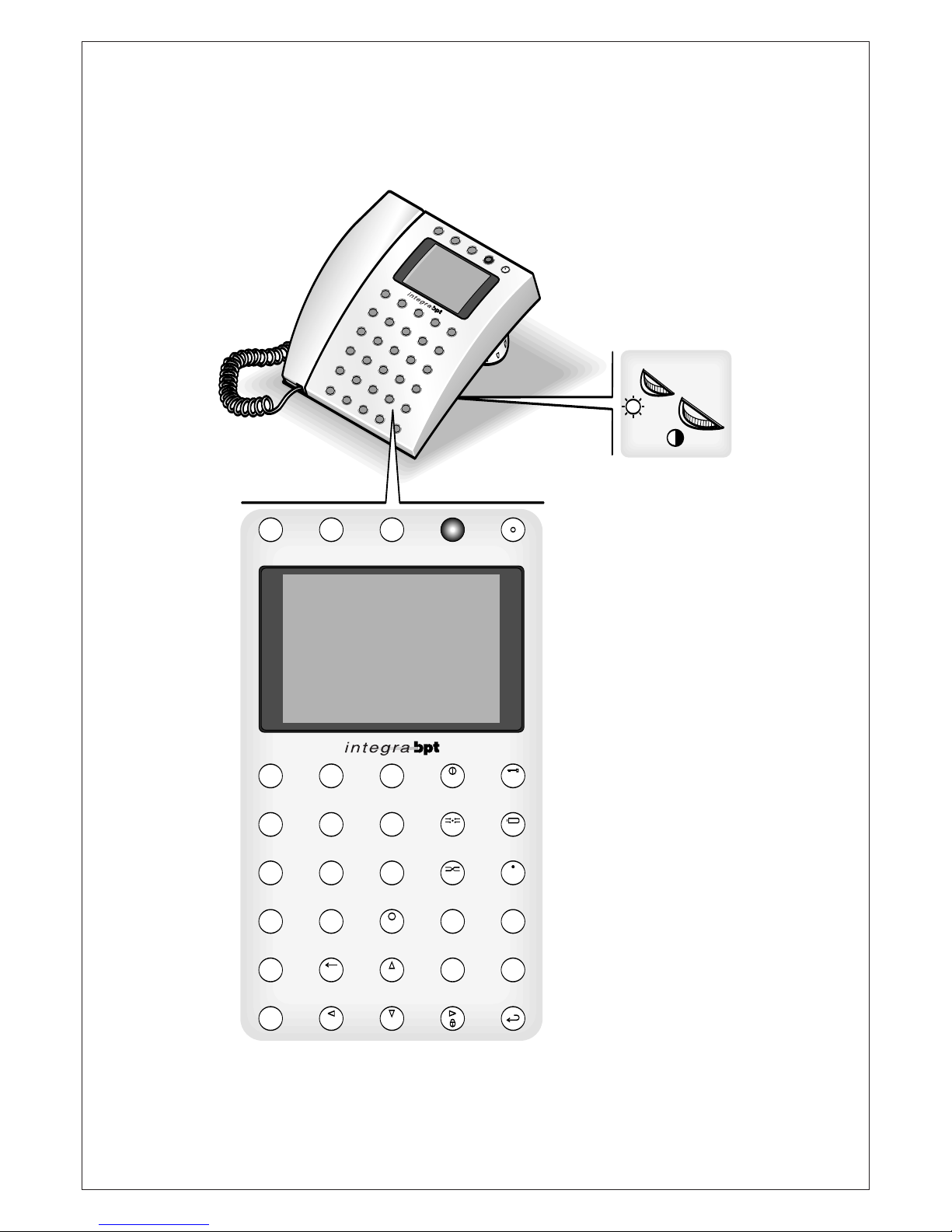
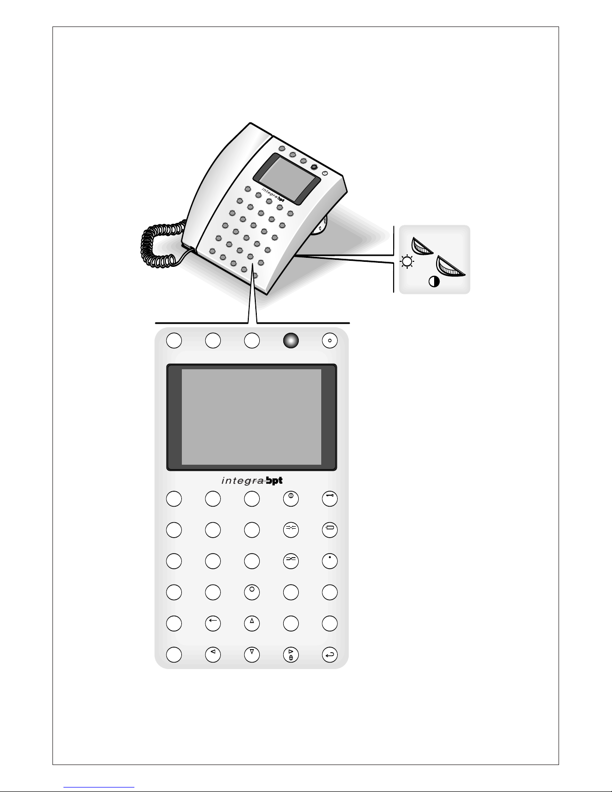
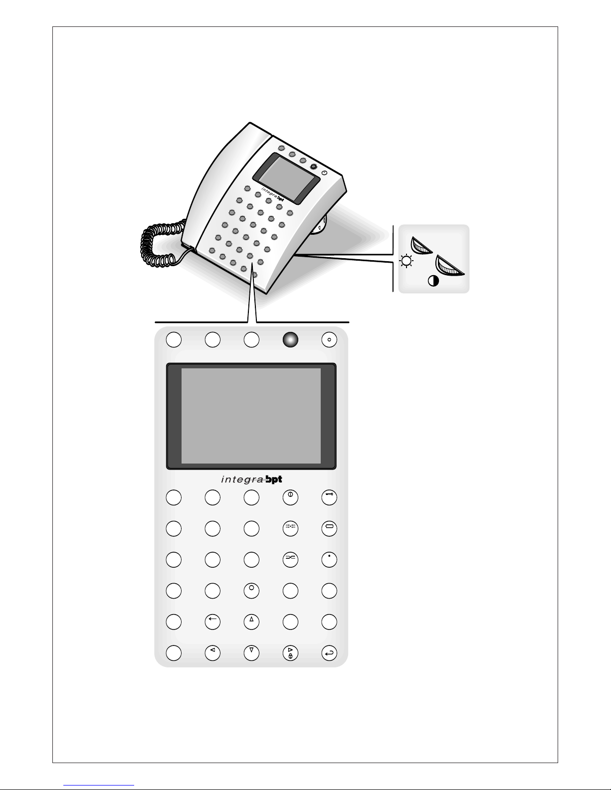
KEYPAD FUNCTIONS
(
fig. 1)
Number 1/Letter A.
Number
2/Letter B.
Number
3/Letter C.
Number
4/Letter F.
Number
5/Letter G.
Number
6/Letter H.
Number
7/Letter K.
Number
8/Letter L.
Number
9/Letter M.
Number
0/Letter Q.
0Q0
9M8
L
7
K
6
H
5
G
4
F
3
C
2
B
1
A
R
eturns to the previous menu or
system reset/Letter
P.
Decimal point/Letter
U.
Select 2
nd
key function.
Press this key once to select
function for single entry; press
twice to keep function enabled.
Deletes pr
evious letter or num-
ber/Letter
V.
Previous letter or number in text
mode/Letter
Z.
Deletes field/Letter
R.
Selects topics/Letter
W.
Selects topics/
Space.
On-Of
f/Letter
D.
Interception/Letter
I.
I
D
_
W
R
C
Z
V
2nd F
U
E
SC
P
T
ransfer/Letter
N.
Sends message from porter/
Letter
S.
Alphanumeric blocks/Letter
X.
Next letter or number in text
mode/Selects upper-lower case.
Door lock release/Letter
E.
Self-connection/Letter
J.
Auxiliary/Letter
O.
Silent call/Letter
T.
Function 4/Letter
Y.
Send.
F4
Y
F2
T
O
J
E
F3
X
F1
S
N
CONTROLS
(
fig. 1)
B
rightness
Saturation colour
Page 6
6
LINGUA/LANGUAGE
I
taliano
English
SETUP MENU
L
ingua/Language
Ring volume
Users management
C
alls filter
Call divert
Entry panels selection
S
etup access code
Set clock
Call output mode
RING VOLUMEItali
R
ing disabled
Low volume
Medium volume
H
igh volume
SETUP MENU
Lingua/Language
Ring volume
Users management
Calls filter
Call divert
Entry panels selection
Setup access code
Set clock
Call output mode
R
ecords count: XX
USERS MANAGEMENT
Modify
Delete name
Delete all
RECORD SELECT 1
11
A-Z DIR
-------------------------------------Custom code:
11 XXXXXXXXX
A-Z DIR
-------------------------------------User name:
XXXXXXXXX
Stored record
at pos.: 1
SETUP MENU
Lingua/Language
Ring volume
Users management
Calls filter
Call divert
Entry panels selection
Setup access code
Set clock
Call output mode
2
3
4
ACCESS TO
PROGRAMMING MENU
Switch on the unit by pressing
the key (LED red lights): after
approx. 4 s, the switchboard is
operative.
T
o access the programming
menu, press keys and at
t
he same time and then enter the
access code (preset code:
12345) and confirm with the
key.
T
he unit version is showed on the
same screen.
P
ROGRAMMING MENU
FUNCTIONS
Lingua/Language
Italiano
English (select the desired lan-
guage for the programming
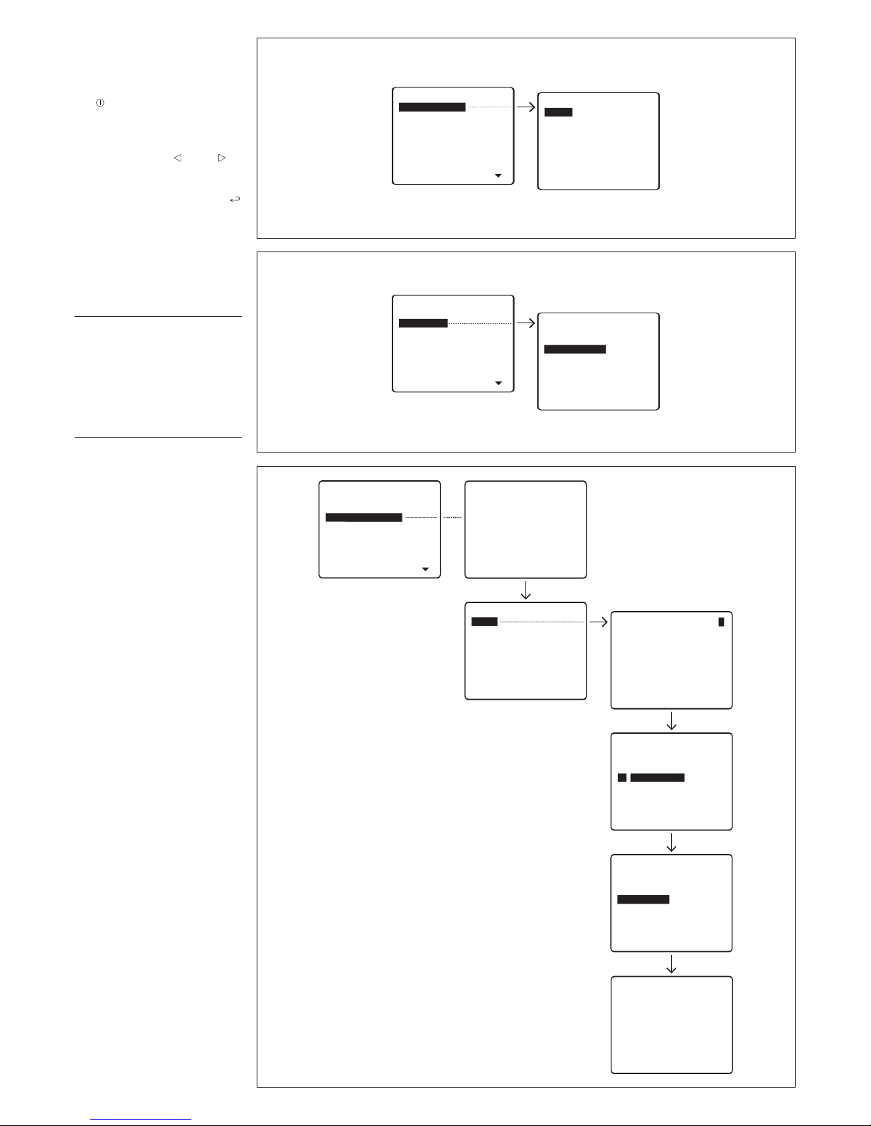
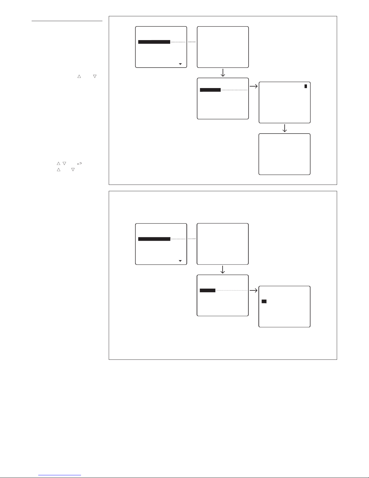
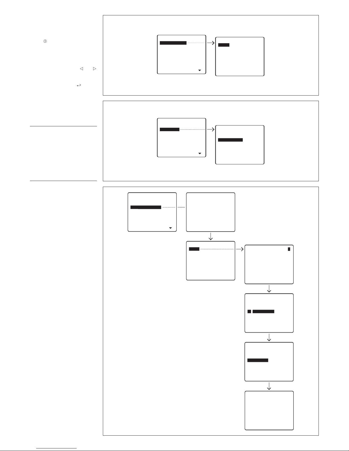
menu messages) (fig. 2).
The language options are Italian
and English.
Ring volume
The available options are (fig. 3):
Ring disabled
Low volume
Medium volume
High volume.
Page 7
7
Records count: XX
USERS MANAGEMENT
Modify
Delete name
Delete all
RECORD SELECT 1
11
Stored record
at pos.: 1
SETUP MENU
Lingua/Language
Ring volume
Users management
Calls filter
Call divert
Entry panels selection
Setup access code
Set clock
C
all output mode
R
ecords count: XX
USERS MANAGEMENT
Modify
Delete name
Delete all
Users deletion
Yes
No
SETUP MENU
Lingua/Language
R
ing volume
Users management
Calls filter
Call divert
Entry panels selection
Setup access code
Set clock
Call output mode
5
6
Users management
Modify (edits the stored user).
T
he following parameters can be
edited and entered for each user
(fig. 4):
Customized code
(max. 9 numbers or letters)
U
ser name
(the following options can be
selected with keys and to
specify the amount of letters or
numbers:
- 1 line with 9 numbers or letters
- 2 lines with 15 numbers or letters
- 4 lines with 20 numbers or lett
ers).
Delete name (deletes a stored
user) (fig. 5).
In the
Modify
and
Delete name
submenus, you can select the
user to be edited or deleted
using keys and .
Keep key or pressed to
scroll though names quickly.
Delete all (deletes all stored
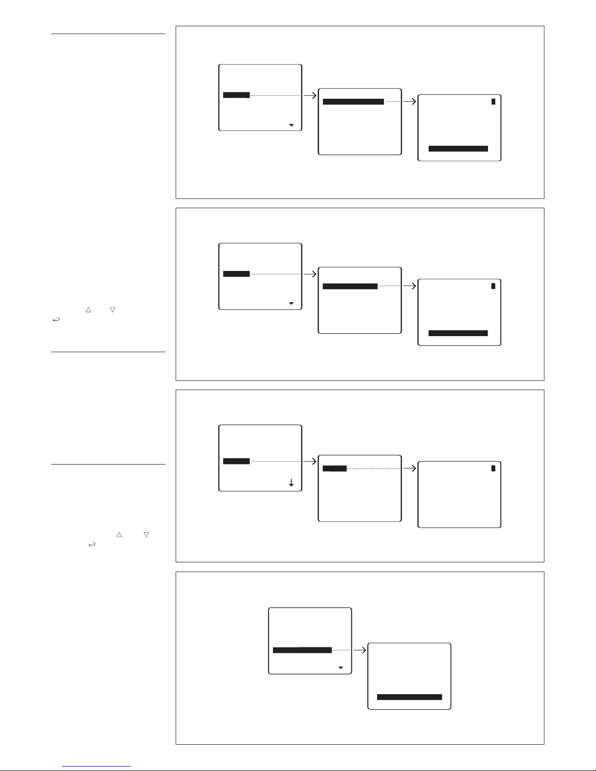
users) (fig. 6).
In the
Delete all
submenu, you
are asked to confirm before all
stored items are deleted.
If you inadvertently delete users,
the default setting for the number
of users (100) can be restored,
or the total number (0-4000) edited.
Page 8
8
CALLS FILTERItali
Calls from entry p. 300
C
alls
f
rom
b
lock
3
00
RECORD SELECT 1
BLOCK1
CALLS ENABLED
SETUP MENU
L
ingua/Language
Ring volume
Users management
C
alls
f
ilter
Call divert
Entry panels selection
S
etup access code
Set clock
Call output mode
RECORD SELECT 1
HAC
SELECTION ENABLED
SETUP MENU
Lingua/Language
Ring volume
Users management
Calls filter
Call divert
Entry panels selection
Setup access code
Set clock
Call output mode
8
10
RECORD SELECT 1
IPD/300
CALL DIVERTItali
To
porter
No divert
SETUP MENU
Lingua/Language
Ring volume
Users management
Calls filter
Call divert
Entry panels selection
Setup access code
Set clock
Call output mode
9
C
ALLS FILTERItali
Calls from entry p. 300
Calls from block 300
RECORD SELECT 1
HAC
CALLS
E
NABLED
SETUP MENU
Lingua/Language
Ring volume
Users management
Calls filter
Call divert
Entry panels selection
Setup access code
Set clock
Call output mode
7
Call filter
In installations with more than
o
ne porter switchboard, this filter
lets you select the 300-series
entry panels and 300-series
blocks enabled to call a specific
switchboard.
Calls from entry panel 300
(
selects 300-series entry panels, panels in the main installation or in the block, enabled to
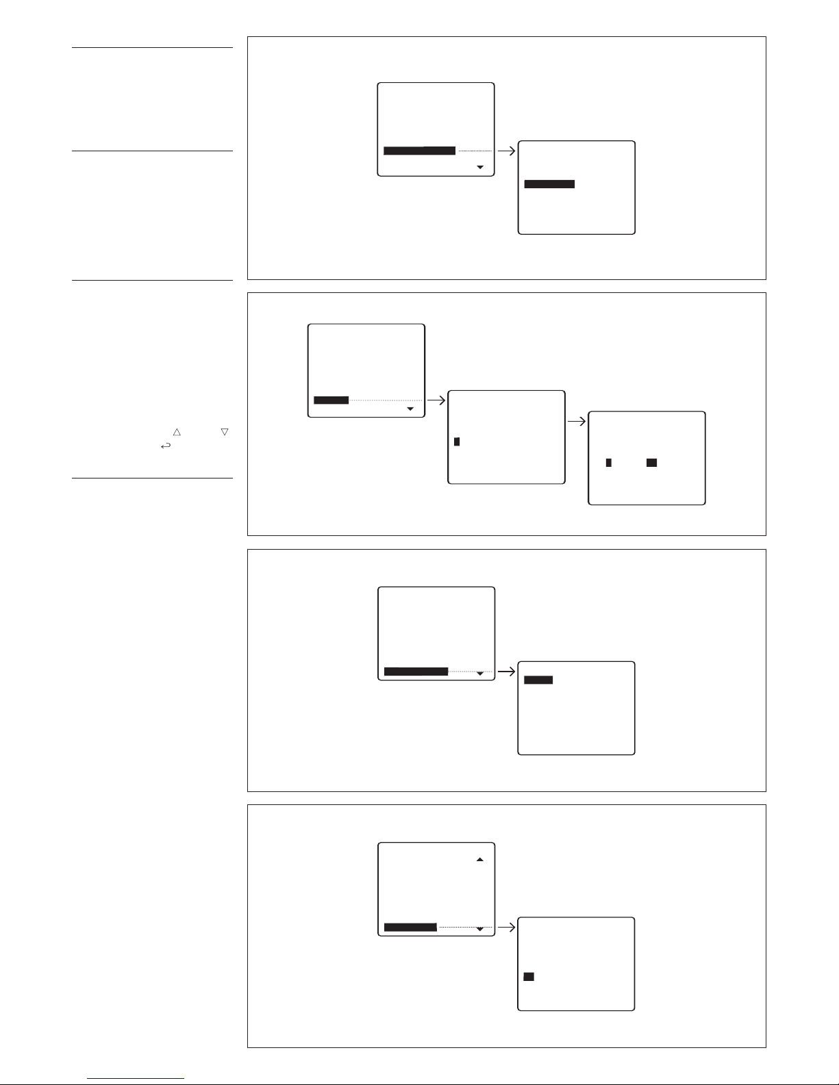
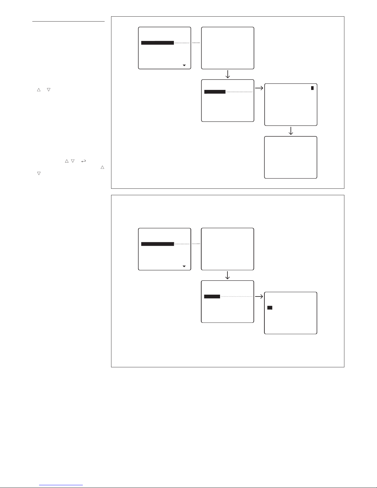
call the switchboard) (fig. 7).
Calls from block 300 (selects
300-series block, with X2
r
eceivers and entry panels,
enabled to call the switchb
oard) (fig. 8).
The unit comes factory set for all
entry panels and all blocks to
call the porter switchboard(s)
inserted in the installation.
The first porter to answer the call
is put through to the caller,
bypassing all other porters.
To disable calls to the porter,
select the entry panel or block
with keys and and press the
key to change the setting (NO
CALLS).
Call divert
For systems with a multiple porter switchboard it is possible to
select the porter for the transfer
of calls directed to a switchboard
that is turned off.
To porter (selection of the switch-
boar
d to which the call is to be
diverted) (fig. 9).
No divert.
Entry panels selection
Setting entry panels by means of
self-connection (fig. 10).
Default setting: all entry panels
are enabled for self-connection.
To skip entry panels when scanning, select the entry panel to be
skipped with keys and and
press the key to confirm disabling of scanning.
Page 9
9
A-Z DIR
--------------------------------------
Stand-by time:
(1-54)
5 min
SETUP MENU
Ring volume
Users management
Calls filter
Call divert
Entry panels selection
Setup access code
Set clock
Call output mode
Stand-by time
14
A-Z DIR
-------------------------------------Setup access code:
12345
S
ETUP MENU
Lingua/Language
Ring volume
U
sers management
Calls filter
Call divert
E
ntry panels selection
Setup access code
Set clock
C
all output mode
A-Z DIR
-------------------------------------Day of week:
(1-7)
1
A-Z DIR
-
------------------------------------Set clock:
hour (0-23) min (0-59)
1 : 00
SETUP MENU
Lingua/Language
R
ing volume
Users management
Calls filter
C
all divert
Entry panels selection
Setup access code
S
et
c
lock
Call output mode
11
12
CALL OUTPUT MODE
All
calls
Alarm calls only
Ext. panel calls only
SETUP MENU
Lingua/Language
Ring volume
Users management
Calls filter
Call divert
Entry panels selection
Setup access code
Set clock
Call output mode
13
Setup access code
Sets code required to access
s
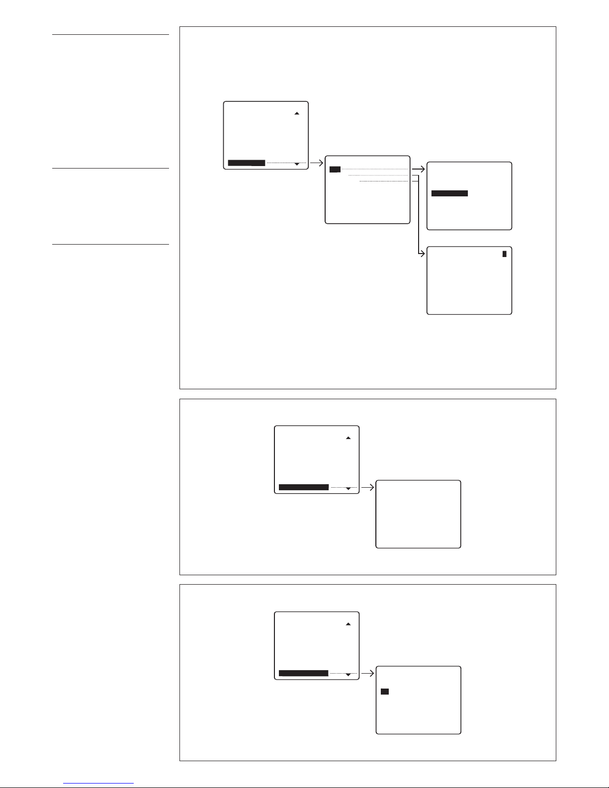
etup menu (fig. 11).
The default code is
12345.
Up to
9 numbers and letters can be
entered.
Set clock
If a clock is present in the
s
ystem, it is possible to set the
clock parameters directly from
the switchboard (days of the
week, hours and minutes) (fig.
12).
C
all output mode
Enables you to select the call
status output mode available for
additional bells (fig. 13).
Default setting: call status output
is enabled for any incoming call.
The output can be set so that it is
activated only when alarm calls
are received, or only when calls
are received from the entry
panel, by selecting the relevant
mode with keys and .
Confirm with the
key
.
Stand-by time
Sets how long the switchboard
may remain idle before screen
goes blank (fig. 14).
Default time is 5 min. This setting
can be edited by entering a time
in the range 1 to 54 min.
The relevant status is indicated
by the stand-by LED flashing. To
switch the screen back on, sim
-
ply pr
ess any key
.
Page 10
10
SETUP MENU
Calls filter
Call divert
Entry panels selection
Setup access code
Set clock
Call output mode
Stand-by time
(F3) key texts
Export all memory
Exporting
Memory ...........
Overwrite memory
Yes
No
SETUP MENU
Call divert
Entry panels selection
Setup access code
Set clock
Call output mode
Stand-by time
(F3) key texts
Export all memory
Import all memory
16
17
A
-Z DIR
-------------------------------------(F3) key label:
XXXX12345
(F3) KEY TEXTSItali
Add
Modify
Delete one
R
ECORD SELECT 1
SETUP MENU
Users management
Calls filter
Call divert
Entry panels selection
Setup access code
Set clock
Call output mode
Stand-by time
(F3) key texts
15
(F3) key texts
This allows you to insert texts in
o
rder to effect the call without
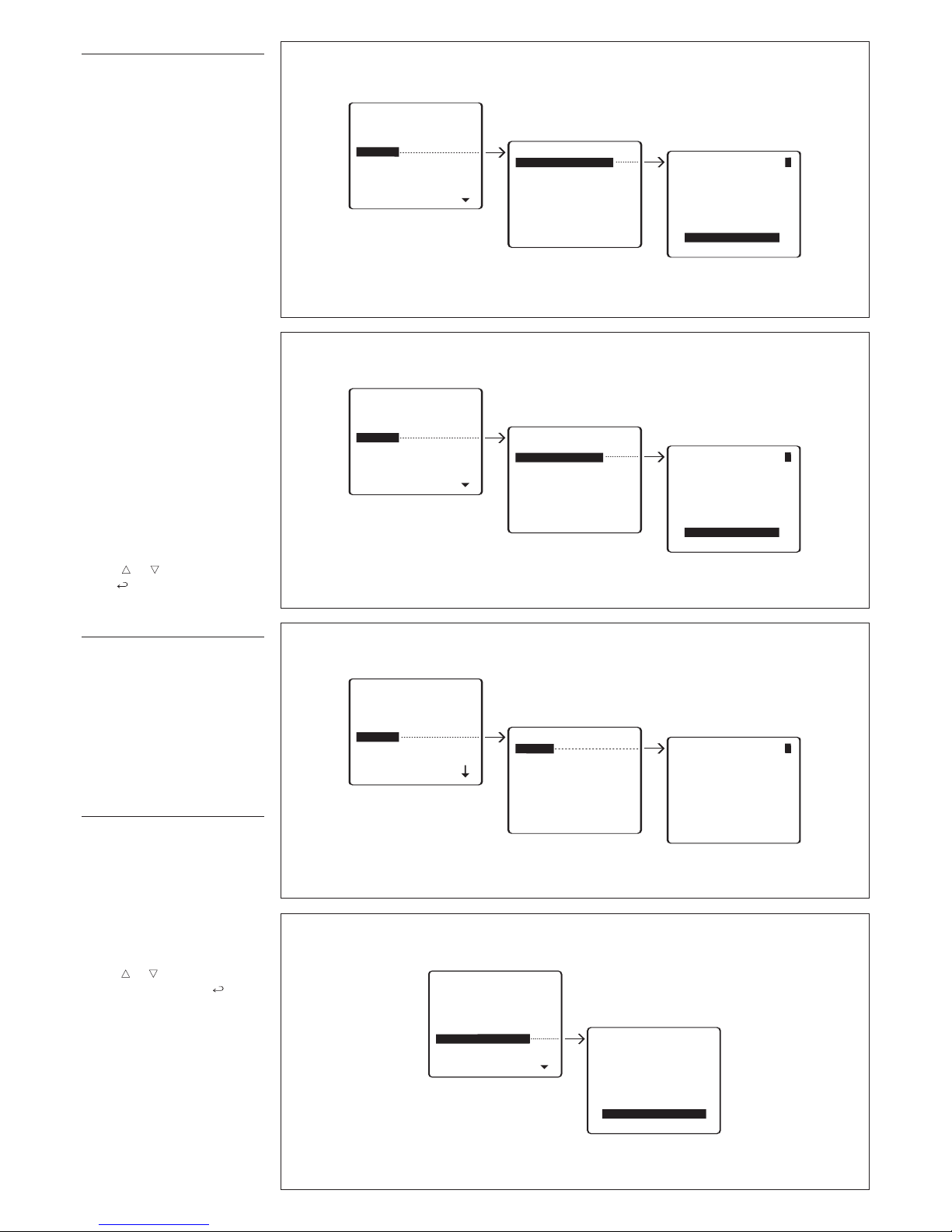
using the alphabet keys (fig. 15).
Add
Type in the text that you wish to
insert (9 max. numbers or lett
ers).
Modify/Delete one
S
elect the text that you wish to
change or cancel and press
SEND to confirm.
Export all memory
Exports IPD/300LR memory (fig.
1
6).
Once the export procedure is
r
un, it can be aborted using the
ESC
key.
Import all memory
Imports IPD/300LR memory (fig.
17).
To perform this operation, the
first porter must be set to memory export mode.
You will be asked to confirm
before the device’s memory is
overwritten.
Page 11
11
Search devices
Yes
N
o
SETUP MENU
Setup access code
Set clock
Call output mode
Stand-by time
(F3) key texts
Export all memory
Import all memory
Memory deletion
Search•devices
19
Memory deletion
Yes
N
o
S
ETUP MENU
Entry panels selection
Setup access code
S
et clock
Call output mode
Stand-by time
(
F3) key texts
Export all memory
Import all memory
D
elete
a
ll
m
emory
18
Delete all memory
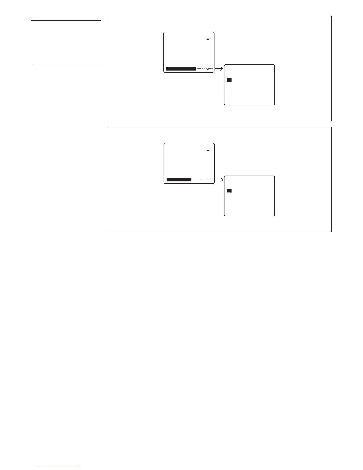
Erases IPD/300LR memory (fig.
1
8).
You will be asked to confirm
before the device’s memory is
deleted.
S
earch devices
I
mports ID codes and descrip-
tion of devices from system (fig.
19).
You will not need to use this function if you have a programmer
version 1.00 or higher as the
entry panels’ data are sent to the
s
witchboard during the installa-
tion’s setup.
Y
ou will be asked to confirm
before the list of devices is overwritten.
Page 12
12
1
A
2
B
3
C
ED
4
F
5
G
6
H
I J
7
K
8
L
9
M
N
O
ESC
P
0
Q
R
C
F1
S
F2
T
F4
Y
F3
X
W
_
Z
2nd F
.
U V
1
Page 13
13
Maximum conversation time can
b
e edited in the range 1 to 255 s
with the XA/300LR customization
o
ption using software
PCS/300LR.
C
ALL USING
CUSTOMIZED CODE
1) Key the customized code in
directly using the numerical keypad.
2) Lift the receiver.
3) Send the call with the key .
It is not necessary to type in the
complete code if you use the
pre-set texts that can be selected using the
F3 key.
A
NSWERING A CALL
FROM ENTRY PANELS
When a porter call is received
from the entry panel, the switchboard emits a call note that lasts
for a preset time of 30 s (can be
edited in the range 1 to 255 s
with the IPD/300LR customization option using softwar
e
PCS/300LR), and the description
of the entry panel the call is
made from flashes on screen.
If the entry panel features a camera, the relevant image will
appear in the background (in
installations with more than one
porter switchboard, the image is
displayed when the receiver is
lifted).
At this point, the door lock
release or auxiliary command
can be sent directly without lifting
the receiver, and current communication cut of
f by pr
essing the
ESC key, or the porter call
answered by lifting the receiver.
Conversation time with the entr
y
panel is determined by the
switchboard by replacing the
r
eceiver or pr
essing the
ESC
key
. Whatever the case, the maximum time is 4 min.
If there is no answer before the
call time is up, the description of
the entry panel the call is made
fr
om is stor
ed in the
Call from
entry panel.
To delete the stored call (up to 10),
you have to press the key.
ANSWERING
A
CALL
FROM RECEIVERS
Following a call to the porter sent
by the r
eceiver
, the switchboar
d
generates a call note lasting 30 s
and the scr
een featur
es: the
associated name (if entered),
customized code, total number
of calls not dealt with (up to 50)
and the or
der in which they
came in.
T
o call users in the or
der of their
respective incoming calls, simply lift the switchboard receiver
and pr
ess the
key
.
If you want to call users in a dif-
INSTRUCTIONS FOR
USING THE UNIT
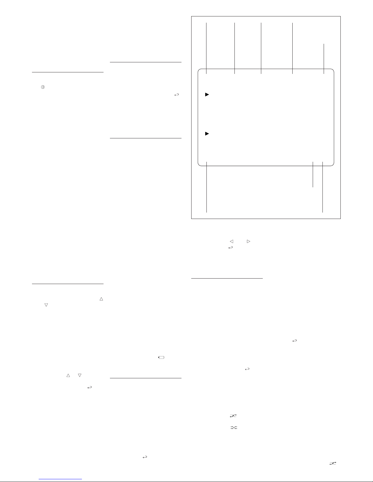
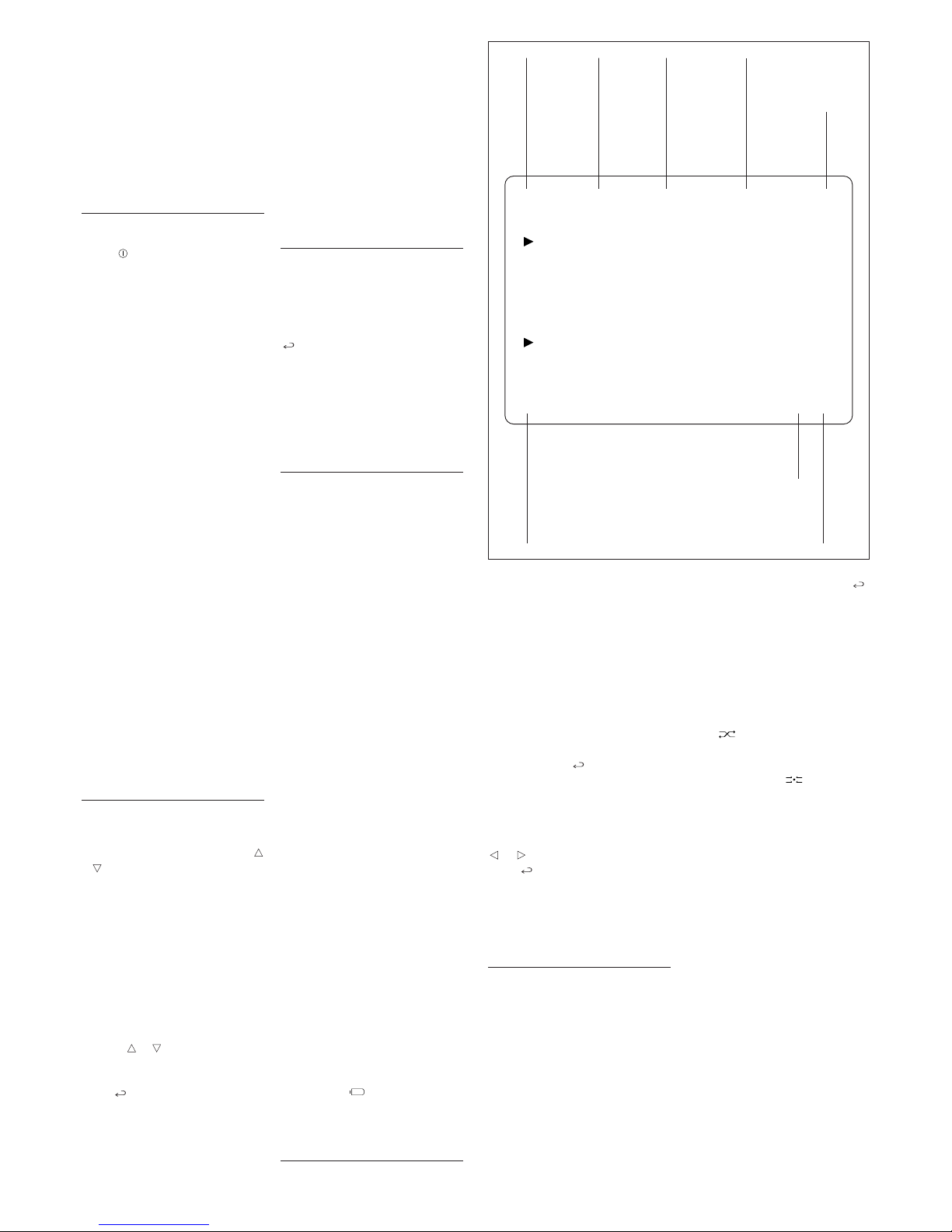
When the switchboard is operating, the display gives the information illustrated in fig. 2.
SWITCHING THE
S
WITCHBOARD ON/OFF
Switch on the unit by pressing
the key (LED red lights): after
approx. 4 s, the switchboard is
operative.
A low note sounds to indicate
standby status when the unit is
s
witched on and any incorrect
commands entered, whilst a
higher note sounds when keys
are pressed correctly.
After the switchboard has
remained idle for a time programmable in the range 1 to 54
min, its monitor switches to
standby.
T
he red LED flashes to indicate
this status.
The monitor automatically
switches back on when any key
is pressed or when the switchboard receives a call.
To switch off the switchboard,
exit any currently running procedures (
ESC key) and press the
stand-by key for at least 1 s (the
red LED goes blank).
If the call diversion is set to
another switchboard (see programming chapter on page 8),
when you switch off the appliance, all calls received will be transferred automatically.
CALL USING NAME
SEARCH FEA
TURE
1) Select the user name or por
ter
to be called by pr
essing keys
and briefly (if there is no
name, the customized code is
displayed).
Scanning is performed in alphabetical or
der in this or
der of prior
ity: space, numbers and letters.
Every time the key is pressed, the
next name appears whilst, if the
key is kept pr
essed, a sear
ch is
performed by scrolling through
the initial letters in alphabetical
order or reverse order depending
on whether key or is used.
2) Lift the receiver.
3) Send the call with the
key
.
If a porter camera has been
enter
ed in the video entr
y con
trol installation (by means of
softwar
e PCS/300LR, supplied
with the interface IPC/300LR),
the camera’s image appears on
the porter’s screen and receiver
’
s monitor
.
Maximum conversation time
depends on the setting contained in the power supplier connected to the receiver (factory
setting: 60 s).
ferent order of priority, instead,
simply select the receiver to be
called with keys and , and
confirm with the key.
Any unwanted calls can be
deleted using the © key.
CALLS
INTERCEPTION/TRANSFER
Switchboards in non-interception
mode (direct mode) only receive
calls from the entry panel intended for the actual porter (corresponding to the first key on
pushbutton panels, or to key
P
on digital panels).
If is transpires from the conversation with the entry panel that a
caller wishes to talk with a user,
the porter can call the user
immediately without r
eplacing
the receiver by keying in or
selecting the relevant user code
and confirming with the
key
.
Once conversation with the user
is over
, the por
ter can r
esume
communication with the entr
y
panel by pressing the
ESC key
(or replacing the receiver), or
can put the entry panel caller
through to the user with the relevant transfer key .
To switch to interception status,
simply pr
ess the
key briefly
(after approx. 1 s, the
INT mes-
sage appears in the relevant
field to indicate this new status).
Default setting for inter
ception
status: total inter
ception for all
r
eceivers.
To edit this setting, see chapter
entitled
Programming intercep-
tion level
.
In this operating mode, any call
made from the entry panel will be
sent to the switchboard.
The call is announced by an
acoustic note, a (flashing) message indicating which entry
panel the call has been made
from, a message indicating the
customized code of the receiver,
and the image, wher
e applica
ble, displayed on the monitor (for
video entry control installations
only).
When the r
eceiver is lifted, the
switchboard communicates directly with the entry panel.
When the key is pressed, the
call is forwarded to the receiver
(call status is announced by an
acoustic note and the user’s
code flashing), and the entr
y
panel making the call is placed
on standby, and cannot listen in
on the private conversation.
The called receiver can converse with the porter and can
view the image from the entry
panel the call is made from (in
video entry control installations
only) on the monitor.
Once conversation with the user is
over, the porter can resume communication with the entry panel by
pr
essing the
ESC key (or r
eplac
ing the receiver and lifting it
again), or can put the entry panel
caller thr
ough to the user by
pressing the transfer button .
2ndF A-Z 12:00 INT OCC.
-----------------------------------------------------
NAME OF CALLED USER OR
U
SER NUMBER ENTERED
11
USER NAME
FROM RECEIVER 11
----------------------------------------------------E.P. DESCRIPTION 01/01
Enables
keypad’s
2
nd
function
Upper/
lower case
System clock
(where
featured)
Interception
status
DIR = Direct
Busy status
Call from
entry panel
Total no. of
call received
from user
Active
user call
position
2
Page 14

14
SELF-CONNECTION
T
O ENTRY PANELS
T
he switchboard features a dedicated key for self-connection
and scanning of entry panels.
Lift the receiver and press the
key until the desired entry
panel is selected.
Via the selected entry panel, you
can check audio, video (only in
installations featuring 300-series
audio/video entry panels), and
door lock release and auxiliary
controls.
ENTERING/EDITING
U
SER NAMES
Access the programming menu
by pressing keys and at the
same time and then enter the
access code (preset code:
1
2345)and confirm with the
key.
Select the Users management
function with the key and confirm.
PROGRAMMING
INTERCEPTION LEVEL
AND FILTER APPLICATION
FOR PORTER CALLS
To access the interception and
filter activation menu (fig. 3),
press the interception key
for at least 2 s.
USER CALLS INTERCEPTION
The active interception level is
indicated by the symbol , and
you can choose between total
and partial.
To switch to partial interception
mode, select the
Total intercep-
tion
option and press the key:
the new partial interception level
is indicated by the symbol
moving to Entry panel, block and
user interc. modes.
At this point, choose the individual devices to be intercepted by
using keys and to move
through the list, and confirm with
.
Once inside the individual menu,
you can select the type of device
(entry panels, blocks or users)
with keys and
,
then change
active status (
DIRECT or INTER-
CEPTED
) using the
key
.
Press the
ESC key to exit each
individual menu.
Note. 300-series block interception also includes all X2 entry
panels belonging to said block in
the same way that user interception is active for calls from any
entry panel.
If you want to cancel the individual interception settings, you can
select the
Interception reset
function, then press the key
and
Yes when prompted to con-
firm.
For instance, when an individual
user so r
equests, the inter
cep
tion status of a receiver can be
changed without cancelling total
interception so that calls to said
user are automatically intercepted when switching to partial
inter
ception status.
To do this, follow the above-mentioned pr
ocedur
e without chang
-
ing total interception status.
PORTER CALL FILTER
The porter call activation function, in installations with a num
ber of porter switchboards, lets
the porter receive/not receive
calls made to the porter either
fr
om a given entr
y panel (por
ter
calls or intercepted calls) or from
X2 receivers or entry panels
belonging to a given 300-series
block.
By enabling or disabling the filter
, r
egar
dless of settings made
in the IPD/300LR unit’
s pr
ogram
-
ming menu, an area or block
switchboard can switch to general or main level instantly (insofar as the existing communication lines allow).
The unit comes factory set for all
entry panels and all blocks to
call the porter switchboard(s)
inserted in the installation.
The first porter to answer the call
is put through to the caller,
bypassing all other porters.
To activate the filter, select the
Call filter active option using
keys and , and confirm with
the
key
.
3
INTERCEPTION MENU
Total interception
Entry pan. 300 interc.
Blocks 300 interc.
Users interception
Interception reset
Calls filter ON
All calls
Page 15

15
DISPOSAL
Do not litter the environment with
packing material: make sure it is
disposed of accor
ding to the
regulations in force in the country
wher
e the pr
oduct is used.
When the equipment reaches the
end of its life cycle, take measures to ensure it is not discarded in the envir
onment.
The equipment must be disposed of in compliance with the
regulations in force, recycling its
component parts wherever possible.
Components that qualify as r
ecy
clable waste feature the relevant
symbol and the material’s abbreviation.
Page 16

16
Page 17
17
ESPAÑOL
CENTRALITA DE CONSERJERÍA
IPD/300LR US
R 5
INSTRUCCIONES DE USO
B
PT S.p.A.
V
ia Roma 41
30020 Cinto Caomaggiore-Ve-Italy
h
ttp: www.bpt.it/e-mail: [email protected]
LEVITON
LEVITON S de RL de CV
LAGO TANA 43 Col HUICHAPAN CP 11290
MEXICO DF T
el 5082 1040
LEA Y CONSERVE ESTE
INSTRUCTIVO
Page 18

18
Í
NDICE
DESCRIPCIÓN Pág.
CENTRALITA DE CONSERJERÍA IPD/300LR . . . . . . . . . . . . . . . 19
Funciones básicas . . . . . . . . . . . . . . . . . . . . . . . . . . . . . . . . . . . . .19
F
unción de los bornes de la toma VPM/240U . . . . . . . . . . . . . . . .19
Características técnicas . . . . . . . . . . . . . . . . . . . . . . . . . . . . . . . . .19
Funciones del teclado . . . . . . . . . . . . . . . . . . . . . . . . . . . . . . . . . . .21
Regulaciones . . . . . . . . . . . . . . . . . . . . . . . . . . . . . . . . . . . . . . . . .21
ACCESO AL MENÚ DE PROGRAMACIÓN . . . . . . . . . . . . . . . . . .22
Funciones del menú de programación . . . . . . . . . . . . . . . . . . . . . .22
E
lección del idioma del menú . . . . . . . . . . . . . . . . . . . . . . . . . . . .22
Volumen timbre . . . . . . . . . . . . . . . . . . . . . . . . . . . . . . . . . . . . . . . .22
G
estión usuarios . . . . . . . . . . . . . . . . . . . . . . . . . . . . . . . . . . . . . . .23
Filtro llamante . . . . . . . . . . . . . . . . . . . . . . . . . . . . . . . . . . . . . . . . .24
Desvío de llamadas . . . . . . . . . . . . . . . . . . . . . . . . . . . . . . . . . . . .24
Exploración placas exteriores . . . . . . . . . . . . . . . . . . . . . . . . . . . . .24
Código de acceso . . . . . . . . . . . . . . . . . . . . . . . . . . . . . . . . . . . . .25
P
rogramar reloj . . . . . . . . . . . . . . . . . . . . . . . . . . . . . . . . . . . . . . . .25
Modo salida llamada . . . . . . . . . . . . . . . . . . . . . . . . . . . . . . . . . . . .25
T
iempo para stand-by . . . . . . . . . . . . . . . . . . . . . . . . . . . . . . . . . . .25
Textos tecla (F3) . . . . . . . . . . . . . . . . . . . . . . . . . . . . . . . . . . . . . . .26
Exportar memoria . . . . . . . . . . . . . . . . . . . . . . . . . . . . . . . . . . . . . .26
Importar memoria . . . . . . . . . . . . . . . . . . . . . . . . . . . . . . . . . . . . . .26
Tachar memoria . . . . . . . . . . . . . . . . . . . . . . . . . . . . . . . . . . . . . . .27
Búsqueda dispositivos . . . . . . . . . . . . . . . . . . . . . . . . . . . . . . . . . .27
INSTRUCCIONES PARA UTILIZAR EL APARATO . . . . . . . . . . . .29
Encendido/Apagado de la centralita . . . . . . . . . . . . . . . . . . . . . . .29
Llamadas mediante la búsqueda de nombres . . . . . . . . . . . . . . . .29
Llamadas mediante el código personalizado . . . . . . . . . . . . . . . .29
Respuesta a una llamada desde la placa exterior . . . . . . . . . . . . .29
Respuesta a una llamada desde el derivado interno . . . . . . . . . .29
Inter
ceptación/Transferencia de llamadas . . . . . . . . . . . . . . . . . . .29
Autoactivación placas exteriores . . . . . . . . . . . . . . . . . . . . . . . . . .30
Introducción/Modificación de nombres de usuarios . . . . . . . . . . .30
Programación nivel de interceptación
y activación filtro para llamadas al conserje . . . . . . . . . . . . . . . . .30
Interceptación llamadas usuarios . . . . . . . . . . . . . . . . . . . . . . . . . .30
Filtro llamadas al conserje . . . . . . . . . . . . . . . . . . . . . . . . . . . . . . .30
NOTA:este equipo ha sido ensayado y declarado conforme a
los límites establecidos para un dispositivo digital de Clase B,
de acuerdo con el Apartado 15 de las Normas FCC. Estos límites han
sido diseñados para ofrecer una protección razonable contra interferencias perjudiciales en una instalación residencial.
Este equipo genera, utiliza y puede emitir energía de radiofr
ecuencia y
, si no
se instala y utiliza conforme a las instrucciones, puede crear interferencias
perjudiciales para las radiocomunicaciones. Sin embargo, no se garantiza
que no se produzcan interferencias en una instalación concreta.
Si este equipo cr
ea interferencias perjudiciales para la recepción de
radio o televisión, lo cual se puede comprobar apagando y encendiendo el equipo, se recomienda al usuario que intente corregir la interfer
encia adoptando una o varias de las siguientes medidas:
- Modifique la orientación o la posición de la antena receptora.
- Aumente la distancia que separa el equipo del receptor.
- Conecte el equipo a un tomacorriente de un circuito diferente de aquel
al que está conectado el r
eceptor.
- Solicite la asistencia de su distribuidor o de un técnico de radio/TV
cualificado.
Page 19

19
CENTRALITA
DE CONSERJERIA
IPD/300LR
Centralita de conserjería para
sistema 300 con pantalla en
color.
Permite controlar el tráfico de las
llamadas tanto de audiointercomunicacion como de videointercomunicacion procedentes de
los derivados internos (sólo
audio) y de las placas exteriores
(
audio y vídeo).
Las llamadas desde las placas
exteriores principales o desde
bloque pueden ser interceptadas y transferidas a los derivados internos mediante una tecla
dedicada.
El grado de interceptación
puede llegar hasta el derivado
individual.
Puede memorizar hasta 50 llamadas procedentes de los derivados inter
nos y despachar la
lista de llamadas siguiendo o no
el orden de prioridad de llegada.
Permite explorar las placas exteriores programadas.
El aparato tiene un cable con
clavija para la conexión a la
toma VPM/240U.
FUNCIONES BÁSICAS
• Único dispositivo para
audiointercomunicacion y
videointercomunicacion
La presencia de un OSD en la pantalla permite visualizar mensajes,
códigos de llamada, archivo de nombres, estado de los usuarios, etc.,
además que la visualización nor
mal
de las imágenes desde las placas
exteriores.
Es siempre posible añadir una
pantalla suplementaria, administrada por una salida de la centralita de conserjería.
En tal caso basta añadir un
receptor vídeo VRX/100.
•
No necesita selectores
exteriores específicos
La centralita de conserjería se
conecta a la instalación como
cualquier placa exterior principal.
En las instalaciones de videointer
comunicacion es necesario
utilizar el distribuidor vídeo
XDV/303.
•
Interceptación de
llamadas generales,
de bloque e individuales
Es posible seleccionar el nivel
de interceptación de las llamadas de usuarios desde la placa
exterior seleccionando todas las
llamadas o individualmente por
instalaciones de bloque, por pla-
cas exteriores o por usuario.
•
Transferencia de llamadas
interceptadas o llamadas para
el conserje
L
a centralita de conserjería per-
mite:
-
la comunicación con derivado
interno e imagen vídeo de la
placa exterior;
- la aceptación de la comunicación por parte del usuario y
transferencia audio/vídeo del llamante mediante tecla dedicada;
- la no aceptación de la comunicación por parte del usuario y
regreso de la comunicación a la
placa exterior llamante.
•
Introducción de nombres
de usuarios con el teclado
La tecla 2ndF facilita la introducción en la memoria de los nombres de usuarios y permite
seleccionar el texto en mayúsculas y minúsculas.
•
T
ransferencia del contenido
de la memoria a otro conserje
En caso de varias centralitas de
conserjería está prevista la posibilidad de transferir todo el contenido de la memoria desde un
conserje a otro.
•
Llamada al derivado interno
con nota diferente
La llamada desde conserje es
efectuada con una nota particular y en presencia de pantalla es
mostrado el texto del conserje
(modificable previa programación).
•
Memorización de llamadas
para el conserje
La centralita de conserjería
memoriza hasta 50 llamadas pr
o
cedentes del usuario, que son
listadas por or
den de llegada.
•
Exploración placas
exteriores en manual
Es posible, si la instalación no
está ocupada o si, en presencia
de una segunda línea principal,
la placa exterior seleccionada
resulta libre, ponerse en comunicación audio/vídeo con las pla
cas exterior
es pr
ogramadas.
• Comando apertura puerta
Como consecuencia de una lla
mada desde la placa exterior o
por autoactivación, se puede
accionar el comando abr
epuerta
de la entrada seleccionada.
•
Regulación volumen
nota de llamada a la centralita
E
l volumen de llamada es configurable en el menú de configur
ación con 3 niveles.
• Funciones multiconserje
El aparato permite utilizar, en la
m
isma instalación, varias centralitas de conserjería configuradas
c
omo varios conserjes principales (funcionamiento en paralelo
con usuarios compartidos) o
como conserjes de bloque (funcionamiento individual con usuarios diferentes).
•
L
lamada para conserje
desde los derivados internos
utilizando comandos
auxiliares
E
s posible configurar la instalación de manera que, en presenc
ia de varias centralitas de conserjería con funcionamiento en
paralelo, se pueda llamar a un
determinado conserje.
•
Llamada de bloques
alfanuméricos
Permite seleccionar unos textos,
memorizados con anterioridad, y
añadirlos a los números tecleados, a fin de efectuar llamadas
con código personalizado sin
utilizar las teclas alfabéticas.
•
Desvío de llamadas hacia
otro conserje
Es posible transferir las llamadas, dirigidas al conserje, a otro
conserje predeterminado de
forma automática cuando se
apaga la centralita.
• Reset instalación
Es posible, a ser necesario,
enviar un mando de reset que
ponga todas las comunicaciones de la instalación en las con
-
diciones de reposo.
FUNCIÓN DE LOS BORNES
DE LA TOMA VPM/240U
1 señal vídeo positiva
2 señal vídeo negativa
3 señal vídeo positiva
4 señal vídeo negativa
5 masa alimentación
6 +14÷18V alimentación
7 audio
8 audio
9 línea datos LON
10 línea datos LON
11 salida tonos conserje
12 salida estado llamadas
13 salida monitor ON
CARACTERÍSTICAS
TÉCNICAS
• Estándar PAL/NTSC.
• Display: LCD TFT de colores
de 3,5”.
• Alimentación: 14÷18 Vcc.
• Consumo: stand-by 100 mA,
a
ctivo 300 mA max.
• Audio: de tipo balanceado
s
istema 2, Z=100
Ω.
• Vídeo: de tipo balanceado
+/–0,6 Vpp, Z=100
Ω.
•
Bus datos: RS-485 78 kb.
• Salida tonos conserje: 5 V con
Rout 1
kΩ.
• Salida estado llamadas/alarma: 5V con Rout 1 kΩ.
• Salida monitor ON: 5 V con
Rout 1 kΩ.
Page 20
20
1
A
2
B
3
C
ED
4
F
5
G
6
H
I J
7
K
8
L
9
M
N
O
ESC
P
0
Q
R
C
F1
S
F2
T
F4
Y
F3
X
W
_
Z
2nd F
.
U V
1
Page 21

21
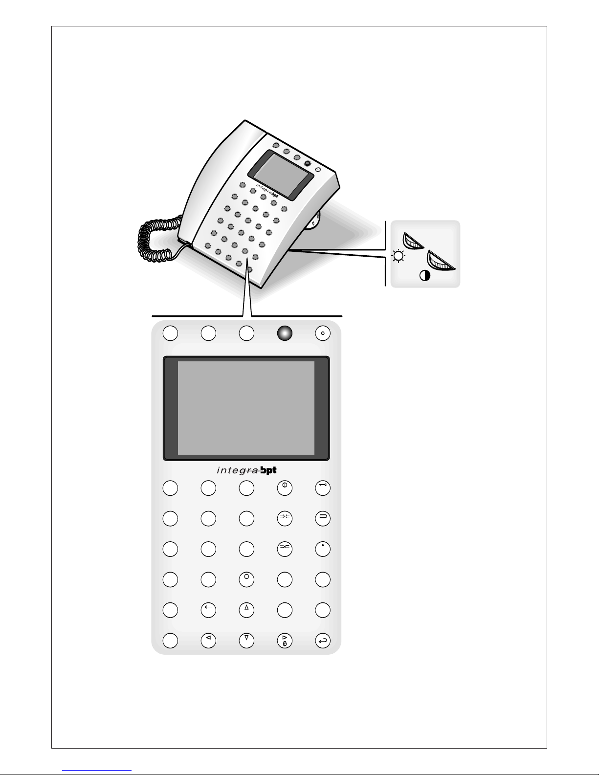
FUNCIONES DEL TECLADO
(
fig. 1)
Número 1/Letra A.
Número
2/Letra B.
Número
3/Letra C.
Número
4/Letra F.
Número
5/Letra G.
Número
6/Letra H.
Número
7/Letra K.
Número
8/Letra L.
Número
9/Letra M.
Número
0/Letra Q.
0Q0
9M8
L
7
K
6
H
5
G
4
F
3
C
2
B
1
A
R
egreso al menú anterior o reset
de la instalación/Letra
P.
Punto/Letra
U.
Selección 2
a
función de las
teclas.
Pulsar una vez esta tecla para
seleccionar la función para un
solo tecleo; pulsar dos veces
para mantener la función siempre activa.
Tachar letra o número anterior/
Letra
V.
Letra o número anterior en
modalidad texto/Letra
Z.
Tachar campo/Letra
R.
Selección temas/Letra
W.
Selección temas/
Espacio.
Encendido-Apagado/Letra
D.
Interceptación/Letra
I.
I
D
_
W
R
C
Z
V
2nd F
U
E
SC
P
T
ransferencia/Letra
N.
Envío mensaje desde conserje/
Letra
S.
Bloques alfanuméricos/Letra
X.
Letra o número siguiente en
modalidad texto/Selección minúscula-mayúscula.
Abrepuerta/Letra
E.
Autoactivación/Letra
J.
Auxiliar/Letra
O.
Llamada silenciosa/Letra
T.
Función 4/Letra
Y.
Intr
o.
F4
Y
F2
T
O
J
E
F3
X
F1
S
N
REGULACIONES
(
fig. 1)
B
rillo
Saturación color
Page 22
22
LINGUA/LANGUAGE
I
taliano
English
SETUP MENU
L
ingua/Language
Ring volume
Users management
C
alls filter
Call divert
Entry panels selection
S
etup access code
Set clock
Call output mode
RING VOLUMEItali
R
ing disabled
Low volume
Medium volume
H
igh volume
SETUP MENU
Lingua/Language
Ring volume
Users management
Calls filter
Call divert
Entry panels selection
Setup access code
Set clock
Call output mode
R
ecords count: XX
USERS MANAGEMENT
Modify
Delete name
Delete all
RECORD SELECT 1
11
A-Z DIR
-------------------------------------Custom code:
11 XXXXXXXXX
A-Z DIR
-------------------------------------User name:
XXXXXXXXX
Stored record
at pos.: 1
SETUP MENU
Lingua/Language
Ring volume
Users management
Calls filter
Call divert
Entry panels selection
Setup access code
Set clock
Call output mode
2
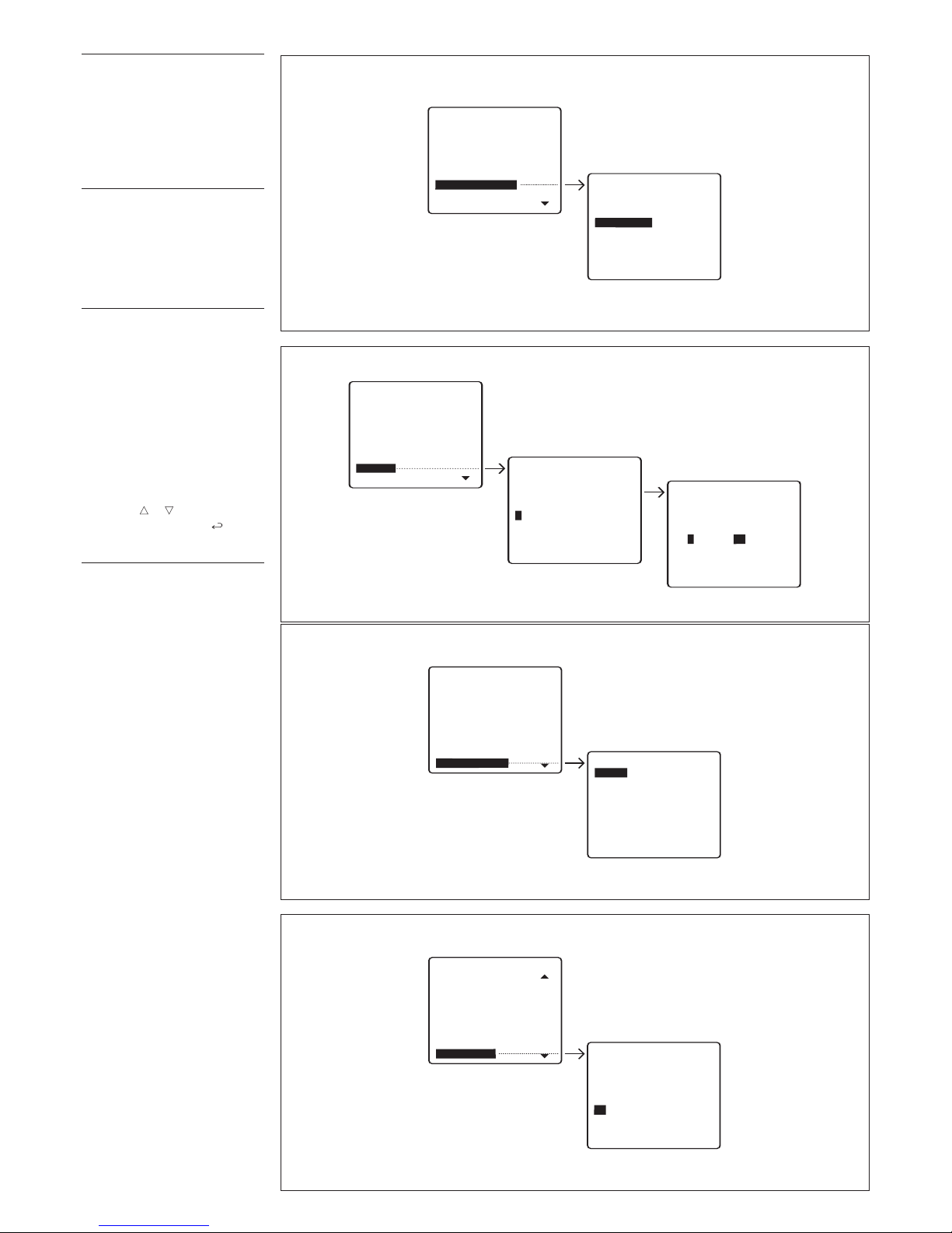
3
4
ACCESO AL MENÚ
DE PROGRAMACIÓN
Encender el aparato pulsando la
tecla (se enciende el LED
rojo): al cabo de unos 4 s la centralita está operativa.
P
ara acceder al menú de programación pulsar contemporán
eamente las teclas y
luego teclear el código de acceso (código predefinido:
12345) y
confirmar con la tecla .
E
n la misma pantalla es mostrada la versión del aparato.
FUNCIONES DEL MENÚ
DE PROGRAMACIÓN
Lingua/Language
Italiano
E
nglish (selección tipo de idioma
deseado para los textos del
menú de programación) (fig.
2).
Los idiomas seleccionables son
el italiano y el inglés.
Ring volume
Se puede elegir entre (fig. 3):
Ring disabled (timbre inhabilitado)
Low volume (volumen bajo)
Medium volume (volumen me-
dio)
High volume (volumen alto).
Page 23
23
Records count: XX
USERS MANAGEMENT
Modify
Delete name
Delete all
RECORD SELECT 1
11
Stored record
at pos.: 1
SETUP MENU
Lingua/Language
Ring volume
Users management
Calls filter
Call divert
Entry panels selection
Setup access code
Set clock
C
all output mode
R
ecords count: XX
USERS MANAGEMENT
Modify
Delete name
Delete all
Users deletion
Yes
No
SETUP MENU
Lingua/Language
R
ing volume
Users management
Calls filter
Call divert
Entry panels selection
Setup access code
Set clock
Call output mode
5
6
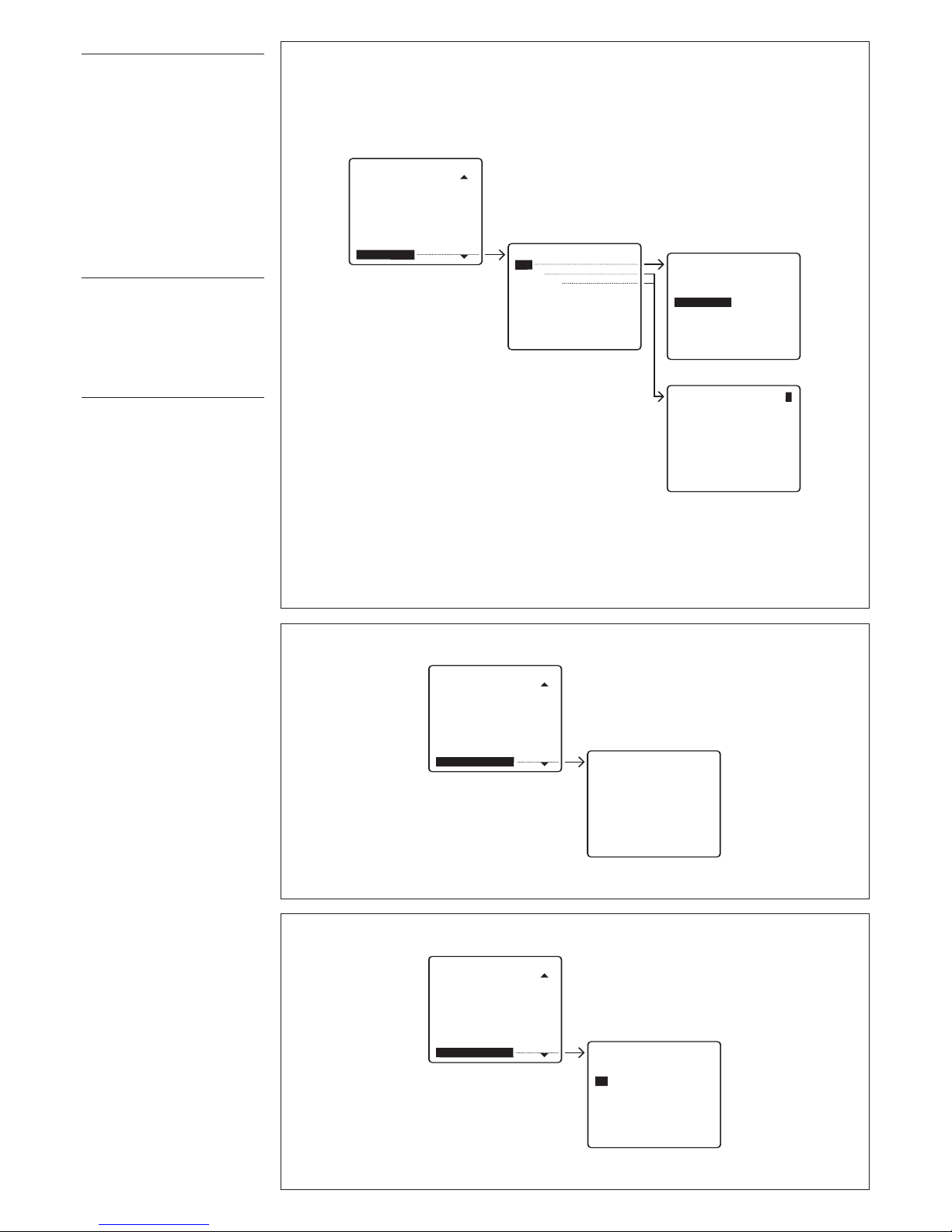
Users management
Modify (modifica usuario memo-
r
izado).
Para cada usuario se pueden
modificar e introducir los
siguientes parámetros (fig. 4):
Código personalizado
(
máx 9 números o letras)
Nombre usuario
(
número de letras o números
seleccionables con las teclas
y entre:
- 1 raya de 9 números o letras
- 2 rayas de 15 números o
letras
- 4 rayas de 20 números o letras).
Delete name (tacha un usuario
memorizado) (fig. 5).
En los submenús
ModifyyDelete
name
es posible seleccionar el
usuario a modificar o a tachar
con las teclas y .
Manteniendo pulsada la tecla
o la búsqueda es rápida.
Delete all (tacha todos los usua-
rios memorizados ) (fig. 6).
En el submenú
Delete all
es
pedida la confirmación antes de
proceder al tachado total.
En caso de tachado involuntario
es posible restablecer el número
de los usuarios intertados de
default (100) o cambiar el número total (0-4000).
Page 24
24
CALLS FILTERItali
Calls from entry p. 300
C
alls
f
rom
b
lock
3
00
RECORD SELECT 1
BLOCK1
CALLS ENABLED
SETUP MENU
L
ingua/Language
Ring volume
Users management
C
alls
f
ilter
Call divert
Entry panels selection
S
etup access code
Set clock
Call output mode
RECORD SELECT 1
HAC
SELECTION ENABLED
SETUP MENU
Lingua/Language
Ring volume
Users management
Calls filter
Call divert
Entry panels selection
Setup access code
Set clock
Call output mode
8
10
RECORD SELECT 1
IPD/300
CALL DIVERTItali
To
porter
No divert
SETUP MENU
Lingua/Language
Ring volume
Users management
Calls filter
Call divert
Entry panels selection
Setup access code
Set clock
Call output mode
9
C
ALLS FILTERItali
Calls from entry p. 300
Calls from block 300
RECORD SELECT 1
HAC
CALLS
E
NABLED
SETUP MENU
Lingua/Language
Ring volume
Users management
Calls filter
Call divert
Entry panels selection
Setup access code
Set clock
Call output mode
7
Call filter
En instalaciones con varias cent
ralitas de conserjería permite
seleccionar las placas exteriores
300 y de los bloques 300 habilitados para llamar a una centralita específica.
Calls from entry panel 300
(
selección de las placas exteriores de tipo 300, placas en la
instalación principal o en el
bloque, habilitadas para llamar
a la centralita) (fig. 7).
Calls from block 300 (selección
d
el bloque de tipo 300, con
derivados internos y placas
e
xteriores de tipo X2, habilitadas para llamar a la centralita)
(fig. 8).
Como condición predefinida,
todas las placas exteriores y
todos los bloques llaman a la/las
centralitas de conserjería presentes en la instalación.
El primer conserje que contesta
a la llamada entra en comunicación con el llamante excluyendo
a los otros conserjes.
Para excluir las llamadas para el
conserje seleccionar la placa
exterior o el bloque con las
teclas y y luego pulsar la
tecla para cambiar la configuración (NO CALLS).
Call divert
En instalaciones con varias centralitas de conserjería, es posible
elegir el conserje al cual transfe
rir las llamadas dirigidas a la
centralita apagada.
To porter (selección de la centra-
lita hacia la cual desviar la llamada) (fig. 9).
No divert (ningún desvío).
Entry panels selection
Configuración de las placas
exteriores seleccionadas mediante autoactivación (fig.
10).
De default todas las placas exte
riores están habilitadas para la
autoactivación.
Para excluir de la selección de
las placas exteriores seleccionar
la placa exterior a excluir con las
teclas y y luego confirmar
pulsando la tecla
para
desactivar la exploración.
Page 25
25
A-Z DIR
--------------------------------------
Stand-by time:
(1-54)
5 min
SETUP MENU
Ring volume
Users management
Calls filter
Call divert
Entry panels selection
Setup access code
Set clock
Call output mode
Stand-by time
14
A
-Z DIR
-------------------------------------Setup access code:
12345
SETUP MENU
L
ingua/Language
Ring volume
Users management
C
alls filter
Call divert
Entry panels selection
S
etup
a
ccess
c
ode
Set clock
Call output mode
A
-Z DIR
-------------------------------------Day of week:
(1-7)
1
A-Z DIR
-------------------------------------S
et clock:
hour (0-23) min (0-59)
1 : 00
SETUP MENU
Lingua/Language
Ring volume
Users management
Calls filter
Call divert
Entry panels selection
Setup access code
Set clock
Call output mode
11
12
CALL OUTPUT MODE
All
calls
Alarm calls only
Ext. panel calls only
SETUP MENU
Lingua/Language
Ring volume
Users management
Calls filter
Call divert
Entry panels selection
Setup access code
Set clock
Call output mode
13
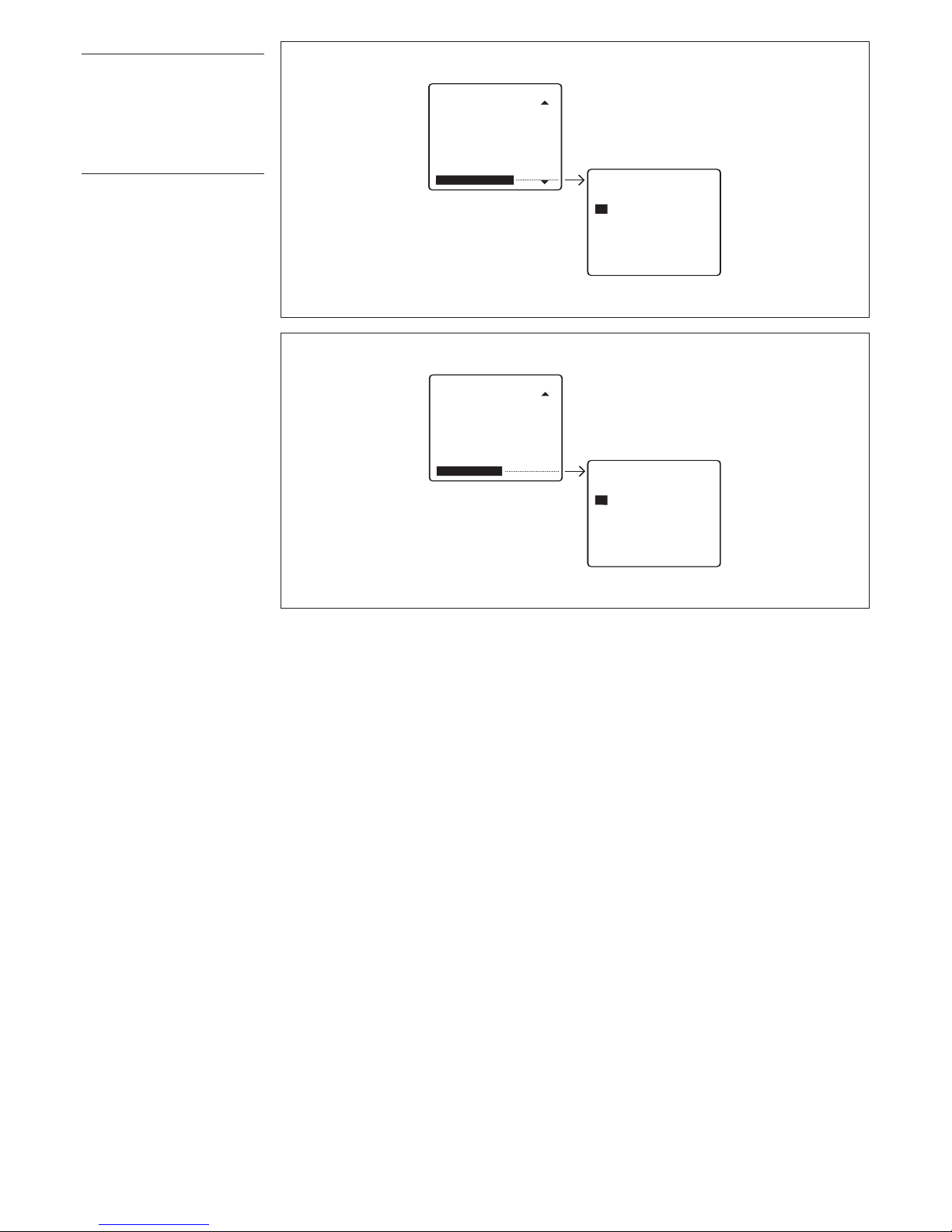
Setup access code
Configuración del código para
a
cceder al menú de configura-
ción (fig. 11).
El código de default es
12345
.
Se pueden introducir hasta 9
números y letras.
Set clock
Si hay un reloj de sistema es
posible programar directamente
desde la centralita los parámetros del reloj (días de la semana,
horas y minutos) (fig. 12).
C
all output mode
P
ermite elegir la modalidad de la
salida estado llamada disponible
para timbres suplementarios (fig.
13).
De default la salida estado llamada está activa para cualquier
llamada entrante.
Es posible configurar la salida
para activarse sólo para las llamadas de alarma o sólo para las
llamadas desde placa exterior
seleccionando la modalidad con
las teclas y .
Confirmar con la tecla .
Stand-by time
Configuración del tiempo de
inactividad antes del apagado
de la pantalla (fig. 14).
El tiempo de default es de 5 min.
Es posible modificar dicha configuración introduciendo un tiempo incluido entr
e 1 y 54 min.
El estado es señalado por la
indicación intermitente del LED
de stand-by. Para reactivar la
pantalla basta pulsar cualquier
tecla.
Page 26
26
SETUP MENU
Calls filter
Call divert
Entry panels selection
Setup access code
Set clock
Call output mode
Stand-by time
(F3) key texts
Export
all
memory
Exporting
Memory ...........
Overwrite memory
Yes
No
SETUP MENU
Call divert
Entry panels selection
Setup access code
Set clock
Call output mode
Stand-by time
(F3) key texts
Export all memory
Import all memory
16
17
A-Z DIR
-------------------------------------(
F3) key label:
XXXX12345
(F3) KEY TEXTSItali
Add
Modify
Delete one
RECORD SELECT 1
SETUP MENU
Users management
C
alls filter
Call divert
Entry panels selection
S
etup access code
Set clock
Call output mode
S
tand-by time
(F3) key texts
15
(F3) Key texts
Permite introducir unos textos
p
ara efectuar la llamada sin utili-
zar las teclas alfabéticas (fig.
15).
Add
Teclear el texto que se desea
i
ntroducir (máx. 9 números o
letras).
M
odify/Delete one
Seleccionar el texto que se
desea modificar o tachar y pulsar
SEND para confirmar.
Export all memory
E
xportación de la memoria
IPD/300LR (fig. 16).
U
na vez activado el proceso de
exportación es posible interrumpirlo con la tecla
ESC
.
Import all memory
Importación de la memoria
IPD/300LR (fig. 17).
Para efectuar esta operación es
necesario predisponer el primer
conserje en exportar memoria.
Es pedida la confirmación antes
de sobrescribir la memoria del
dispositivo.
Page 27
27
Search devices
Yes
N
o
SETUP MENU
Setup access code
Set clock
Call output mode
Stand-by time
(F3) key texts
Export all memory
Import all memory
Memory deletion
Search•devices
19
Memory deletion
Yes
N
o
S
ETUP MENU
Entry panels selection
Setup access code
S
et clock
Call output mode
Stand-by time
(
F3) key texts
Export all memory
Import all memory
D
elete
a
ll
m
emory
18
Delete all memory
Tachado total de la memoria
I
PD/300LR (fig. 18).
Es pedida la confirmación antes
de tachar la memoria del dispositivo.
S
earch devices
I
mportación desde el sistema de
los códigos de identificación y
descripción de los dispositivos
(fig. 19).
No es necesario ejecutar esta
función si se dispone de un programador con versión 1.00 o
s
uperior ya que los datos de las
placas exteriores son enviados a
l
a centralita durante la configura-
ción de la instalación.
Es pedida la confirmación antes
de sobrescribir la lista de los dispositivos.
Page 28
28
1
A
2
B
3
C
ED
4
F
5
G
6
H
I J
7
K
8
L
9
M
N
O
ESC
P
0
Q
R
C
F1
S
F2
T
F4
Y
F3
X
W
_
Z
2nd F
.
U V
1
Page 29
29
2ndF A-Z 12:00 INT OCC.
-----------------------------------------------------
NOMBRE USUARIO LLAMADO O
N
UMERO USUARIO INSERTADO
11
NOME USUARIO
DESDE DERIVADO INTERNO
11
----------------------------------------------------DESCRIPCION P.E. 01/01
Activación
2
a
función
teclado
Texto
mayúsc./
minúsc.
Reloj de
sistema
(si presente)
Estado
interceptación
DIR = Directo
Estado de
ocupado
Llamada desde
placa exterior
N. de llamadas
totales llegadas
desde usuario
Posición
llamada
usuario activa
2
INSTRUCCIONES
PARA LA UTILIZACIÓN
DEL APARATO
Cuando la centralita está encendida en el display aparece la
información mostrada en la fig.
2.
E
NCENDIDO/APAGADO
DE LA CENTRALITA
Encender el aparato pulsando la
tecla (se enciende el LED
rojo): al cabo de unos 4 s la centralita está operativa.
El estado de inactividad al encendido, así como la introducción de comandos erróneos es
señalado por una nota acústica
con tono bajo, mientras que el
tecleo de teclas correctas es
señalado por una nota acústica
c
on tono alto.
Al cabo de un tiempo de inactividad, programable entre 1 y 54
min, el monitor de la centralita
pasa al estado de stand-by.
Esta situación es señalada por la
intermitencia del LED rojo.
La presión de cualquier tecla o
la llegada de una llamada a la
centralita determina el encendido de la pantalla.
Para apagar la centralita salir
primero de eventuales operaciones en curso (tecla
ESC) luego
pulsar la tecla de stand-by
durante por lo menos 1 s (el LED
rojo se apaga).
Si se ha programado la desviación de llamada hacia otra centralita (ver capítulo de programación en la pág. 8), al apagado
del aparato, todas las llamadas
recibidas serán automáticamente transferidas.
LLAMADA MEDIANTE
LA BÚSQUEDA DE NOMBRES
1)Seleccionar el nombr
e del
usuario o del conserje a llamar
pulsando brevemente la tecla
y (a falta del nombre es visualizado el código personalizado).
La exploración se produce por
orden alfabético siguiendo la
prioridad: espacio, números y
letras.
A cada presión de la tecla apar
ece el nombr
e siguiente mien
tras que manteniéndola pulsada,
la búsqueda se produce recorriendo las letras iniciales por
orden alfabético o inverso según
la tecla y utilizada.
2)Descolgar el auricular.
3)Enviar la llamada mediante la
tecla .
Si en la instalación de videointer
comunicacion se ha puesto una
videocámara de conserjería (con
programador MPP/300LR) en la
pantal-la del conserje y del deri
vado apar
ece la imagen de la
videocámara. La duración máxim
a de la conversación depende
de la configuración efectuada en
e
l alimentador conectado con el
derivado (condición predefinida:
60 s).
Es posible modificar el tiempo
máximo de conversación entre 1
y
255 s con el programador
MPP/300LR en la voz personaliz
ación XA/300LR.
LLAMADA MEDIANTE
CÓDIGO PERSONALIZADO
1)Teclear directamente el código personalizado utilizando el
t
eclado numérico.
2)Descolgar el auricular.
3)Enviar la llamada con la tecla
.
E
s posible evitar tener que
teclear el entero código utilizand
o textos programados seleccionados mediante la tecla
F3.
RESPUESTA A UNA
LLAMADA DESDE
LA PLACA EXTERIOR
Ante una llamada para el conserje desde la placa exterior, la
centralita emite una nota de llamada con duración pr
estableci
da de 30 s (modificable entre 1 y
255 s con el programador
MPP/300LR en la voz personalización IPD/300LR) y es visualizada, en modalidad intermitente,
la descripción de la placa exterior llamante.
Ante una placa exterior de videointercomunicacion será visualizada en el fondo de la pantalla,
la imagen de la correspondiente
videocámara (en las instalaciones con varias centralitas de
conserjería la imagen será visualizada cuando se descuelgue el
auricular).
Ahora es posible enviar el comando abrepuerta o auxiliar directamente sin descolgar el auricular y
terminar la comunicación en
curso con la tecla
ESC o bien
contestar a la llamada de conserje descolgando el auricular
.
La duración de la conversación
con la placa exterior es configu
rada desde la centralita colgando el auricular o pulsando la
tecla
ESC y en todo caso está
limitada para un tiempo máximo
de 4 min. Si no se contesta dentr
o sel tiempo de llamada, la
descripción de la placa exterior
llamante será memorizada en el
campo
Call from entry panel.
Para tachar la llamada memori
-
zada (máximo 10) se debe pul
-
sar la tecla .
RESPUESTA A UNA
LLAMADA
DESDE DERIVADO INTERNO
Ante una llamada para el con
-
serje desde el derivado interno,
la centralita genera una nota de
llamada que dura 30 s y visualiza en la pantalla: el nombre asociado (si introducido), el código
personalizado, el número total
de las llamadas por despachar
(máximo 50) y el orden de la
secuencia de llegada.
Para llamar a los derivados internos siguiendo el or
den de llega
da basta descolgar el auricular y
pulsar la tecla .
Si por el contrario se desea llamar a los derivados internos con
una prioridad diferente que la de
llegada basta seleccionar el
derivado a llamar con las teclas
y y luego confirmar con la
tecla
.
Eventuales llamadas indeseadas
se pueden tachar con la tecla ©.
INTERCEPT
ACIÓN/
TRANSFERENCIA
DE LLAMADAS
La centralita, en condiciones de
no interceptación (modalidad
dir
ecta), recibe de la placa exterior sólo las llamadas para el
conserje (correspondiente a la
primera tecla en el caso de placas con pulsador o a la tecla
P
en caso de placas numéricas).
Si en la conversación con la placa
exterior se pide llamar a un deri
vado interno, el conserje puede
llamarlo inmediatamente sin colgar el auricular
, marcando o
seleccionando el código de usua
-
rio y confirmando con la tecla .
Al final de la conversación con el
derivado interno el conserje
podrá volver en comunicación
con la placa exterior pulsando la
tecla
ESC (o colgando el auricu-
lar), o bien podrá poner en
comunicación el derivado interno con la placa exterior utilizando la tecla de transfer
encia pr
e
vista .
Para pasar al estado de interceptación basta pulsar br
eve
mente la tecla (el nuevo
estado es señalado al cabo de
aproximadamente 1 s desde la
indicación
INT en el campo
correspondiente).
Como condición pr
edefinida, la
activación del estado de interceptación prevé la interceptación total de todos los derivados
internos.
Para modificar esta configuración ver el capítulo
Progra-
mación nivel de interceptación.
En esta condición de funcionamiento cualquier llamada efectuada desde la placa exterior
será dirigida a la centralita.
La llamada es r
esaltada por una
nota acústica, por la indicación de
la placa exterior llamante (intermitente), por la indicación del código personalizado del derivado
interno y por la eventual imagen
vídeo en la pantalla (sólo para ins
talaciones de videointercomunicacion).
Descolgando el auricular la centralita queda dir
ectamente en
Page 30

30
comunicación con la placa exter
ior.
Pulsando la tecla la llamada
es enviada al derivado interno
(el estado de llamada es señalado por una nota acústica y por la
intermitencia del código de
usuario) y se pone en estado de
espera la placa exterior llamante, que no puede escuchar la
conversación interna.
El derivado llamado puede conversar con el conserje y verá en
la pantalla (sólo en instalaciones
de videointercomunicacion) la
imagen de la placa exterior llamante.
Al final de la conversación con el
derivado interno, el conserje
podrá pònerse en comunicación
con la placa exterior pulsando la
t
ecla
ESC(
o colgando el auricular y descolgando el auricular) o
p
odrá poner en comunicación el
derivado interno con la placa
exterior pulsando la tecla de
transferencia .
AUTOACTIVACIÓN
DE PLACAS EXTERIORES
La centralita dispone de una
tecla dedicada para la autoactivación y la exploraciónde las
placas exteriores.
Descolgar el auricular y luego
pulsar la tecla hasta que se
selecciona la placa exterior
deseada.
Desde la placa exterior seleccionada es posible efectuar el control audio, vídeo (sólo ante placas exteriores de audiointerco
municacion de la serie 300), el
envío del comando abrepuerta y
auxiliar
.
INTRODUCCIÓN/
MODIFICACIÓN NOMBRES
USUARIO
Acceder al menú de programación pulsando contemporánea
mente las teclas
y
y luego
introducir el código de acceso
(código predefinido:
12345) y
confirmar con la tecla .
Seleccionar con la tecla la
función
Users management y
luego confirmar.
PROGRAMACIÓN NIVEL
DE INTERCEPTACIÓN
Y ACTIVACIÓN FILTRO
PARA LLAMADAS
PARA EL CONSERJE
Para acceder al menú de interceptación y activación filtro (fig.
3) pulsar durante por lo menos 2
s la tecla de interceptación .
INTERCEPTACIÓN
LLAMADAS USUARIOS
El nivel de interceptación activo
viene indicado por la presencia
del símbolo y se puede seleccionar entre total y parcial.
Para pasar a la modalidad de
i
nterceptación parcial seleccio-
nar la voz
Total interception y
pulsar la tecla : el nuevo nivel
de interceptación parcial viene
i
ndicado por el desplazamiento
del símbolo en las modalidades
Entry panel, block and user
interc.
Ahora elegir los dispositivos a
interceptar recorriendo la lista
con las teclas y y confirmando con .
Dentro de cada menú es posible
seleccionar el tipo de dispositivo
(placas exteriores, bloques o
usuarios) con las teclas y
, y
luego cambiar el estado activo
(
DIRECTO o INTERCEPTADO)
con la tecla .
Pulsar la tecla
ESC para salir de
cada menú.
Nota. La interceptación de un
bloque 300 incluye también
todas las placas exteriores de
tipo X2 pertenecientes a ese bloque, así como la inter
ceptación
de usuario está activa desde
cualquier placa exterior.
Si se desea tachar las inter
cep
taciones individuales es posible
seleccionar la función
Intercep-
tion reset
y pulsar luego
seleccionar Yesa la petición de
confir
mación.
Es posible, por ejemplo a petición de cada usuario, cambiar el
estado de interceptación de un
derivado interno, manteniendo
activo el estado de interceptación total, a fin de estar automá
-
ticamente inter
ceptado cuando
se pasa al estado de interceptación parcial.
Para hacer esto seguir las indi
caciones antedichas sin cambiar
el estado de inter
ceptación total.
FILTRO LLAMADAS PARA
EL
CONSERJE
La función de activación del filtro
de llamadas para el conserje
permite, en instalaciones con
varias centralitas de conserjería,
recibir o no llamadas destinadas
al conserje procedentes tanto de
una determinada placa exterior
(llamadas para el conserje o llamadas interceptadas) como
desde derivados internos o placas X2 pertenecientes a un
determinado bloque 300.
La activación o no del filtro, independientemente de las configuraciones hechas en el menú de
pr
ogramación del IPD/300LR,
permite a una centralita de zona
o bloque pasar inmediatamente
a nivel general o principal (compatiblemente con las líneas de
comunicación previstas).
Como condición predefinida
todas las placas exteriores y
todos los bloques llaman a la/las
centralitas de conserjería presentes en la instalación.
El primer conserje que contesta
a la llamada entra en comunicación con el llamante excluyendo
a los otros conserjes.
Para activar el filtro seleccionar,
con las teclas y , la voz
Call
filter active y luego confirmar con
la tecla
.
3
INTERCEPTION MENU
Total interception
Entry pan. 300 interc.
Blocks 300 interc.
Users interception
Interception reset
Calls filter ON
All calls
Page 31

31
ELIMINACION
Comprobar que no se tire al medioambiente el material de
embalaje, sino que sea eliminado conforme a las normas vigentes en el país donde se utilice el
pr
oducto.
Al final del ciclo de vida del
aparato evítese que éste sea
tirado al medioambiente.
La eliminación del aparato debe
efectuarse conforme a las normas
vigentes y privilegiando el r
ecicla
-
je de sus par
tes componentes.
En los componentes, para los
cuales está prevista la eliminación con r
eciclaje, se indican
el símbolo y la sigla del material.
Page 32

32
 Loading...