


1
I
ISTRUZIONI PER
L’INSTALLAZIONE
BPT S.p.A.
30020 Cinto Caomaggiore
Venezia/Italy
11.99/2403-9800
HTS
HBP
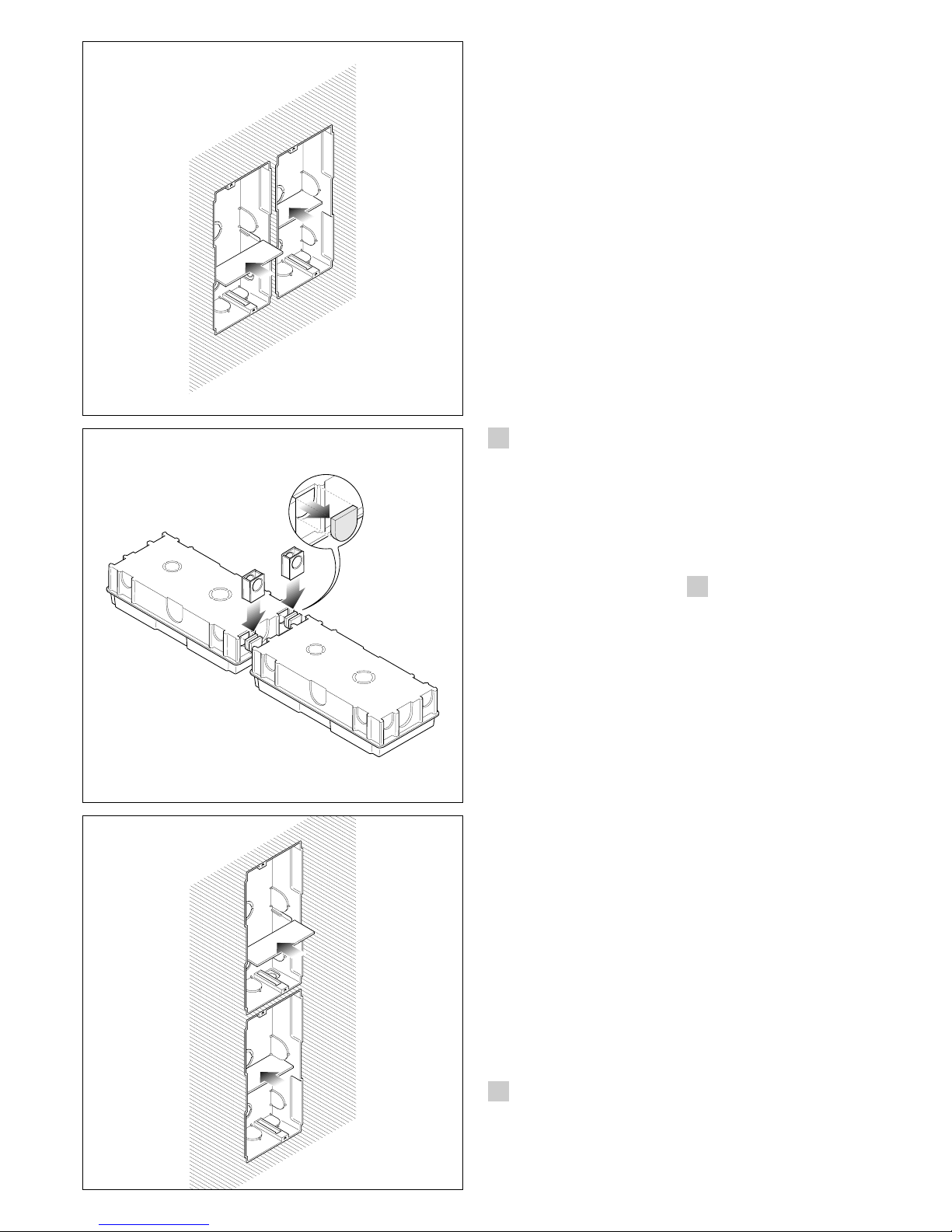
HTS: SCATOLA INCASSO
La scatola incasso va murata a filo
muro e ad un’altezza adeguata. In
caso di posto esterno videocitofonico l’altezza deve essere tale da
sfruttare al meglio le caratteristiche della telecamera.
Per combinazioni in orizzontale
(fig. 1-2) o in verticale (fig. 3-4),
togliere i copriforo e inserire i giunti passacavo.
Nella messa in opera delle scatole
incasso saranno evitate possibili
deformazioni utilizzando l’apposito
distanziale in dotazione (fig. 2-4).
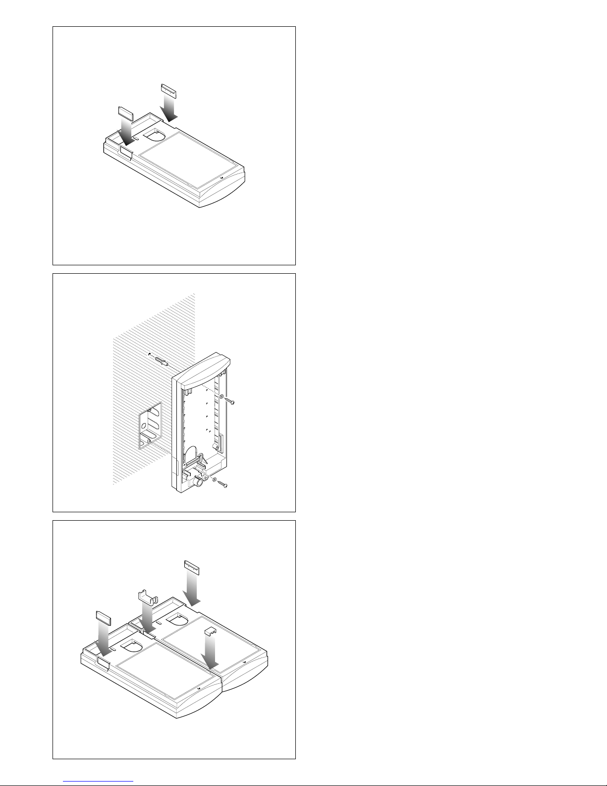
BASE DA PARETE HBP
Applicare i due copriforo alla base
(fig. 5). Murare la scatola incasso
(da 3 moduli o tonda Ø 65 mm) a
filo muro e ad un’altezza adeguata.
In caso di posto esterno videocitofonico l’altezza deve essere tale
da sfruttare al meglio le caratteristiche della telecamera.
Fissare la base al muro utilizzando
le viti ed i tasselli in dotazione (fig.
6).
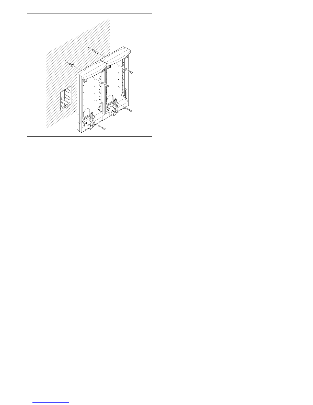
Per combinazioni in orizzontale
(massimo 3 basi), inserire all’esterno i due copriforo, all’interno in
basso il giunto passacavo ed in
alto il giunto (fig. 7).
Fissare le basi al muro utilizzando le
viti ed i tasselli in dotazione (fig. 8).
1
HTS: EMBEDDING BOX
The embedding box must be fitted
flush with the wall at an appropriate height. In the case of video
entry panels, the height should be
such as to exploit the features of
the camera to the full.
GB
INSTALLATION
INSTRUCTIONS
For horizontal (fig. 1-2) or vertical
(fig. 3-4) combinations, remove
the hole plugs and insert the cable
guide joints.
Fit the spacer into embedding boxes
to avoid deformation (fig. 2-4).
SURFACE HOUSING HBP
Apply the two hole plugs at the
base (fig. 5). Fit the embedding
box (3-module or round ø 65mm
version) flush with the wall at an
appropriate height.
In the case of video entry panels,
the height should be such as to
exploit the features of the camera
to the full.
Fasten the base onto the wall
using the screws and screw
anchors supplied (fig. 6).
For horizontal combinations (maximum 3 bases), insert the two hole
plugs on the outside, at the bottom
inside the cable guide joint and
top inside the joint (fig. 7).
Fasten the bases to the wall using
the screws and screw anchors
supplied (fig. 8).
D
INSTALLATIONSANLEITUNG
HTS: UP - KASTEN
Der UP - Kasten muß in angemessener Höhe bündig zur Mauer hin
eingemauert werden. Bei einer
Außenstation für Videosprechanlagen muß die Höhe die maximale Ausnutzung der Eigenschaften der Fernsehkamera ermöglichen.
Für horizontale (Abb. 1-2) oder
vertikale (Abb. 3-4) Kombinationen sind die Abdeckklappen
abzunehmen und die Kabelführungsverbindungen einzufügen.
Bei der Montage des UP-Kasten
werden mögliche verformungen
vermeidet wenn man den
bestimmten Abstandshalter verwendet (Abb. 2-4).
12
1)Scatola incasso/Embedding box/
Up-Kasten/Boîtier d’encastrement/
Caja de empotrar/Caixa de enca-
stre.
2)Telaio/Chassis/Chassis/Châssis/
Bastidor/Chassis.
3)Giunti passacavo/Cable guide
joints/Abstandsstücke/Joints passe-câble/Juntas pasacable/Juntas
passacabo.
3
4
4)Distanziale/Spacer/Abstandshalter/
Pièce d’entroisement/Separador/
Distancial.
5)Viti e tasselli/Screws and anchors/
Dübeln und Schrauben/Vis et che-
villes/Tornillos y tacos/Parafusos e
buchas.
12
1)Base da parete/Surface housing/
Wandbasis/Support pour paroi/
Base de pared/Base de parede.
2)Copriforo/Hole plugs/Abdeckkap-
pen/Cache-trous/Tapa-agujero/
Tapa furos.
3)Giunto passacavo/Cable guide
joint/Abstandsstücke/Joint passecâble/Junta pasacable/Junta pas-
sacabo.
3
4 5
4)Giunto/Joint/Verbindung/Joint/Junta/
Junta.
5)Viti e tasselli/Screws and anchors/
Dübeln und Schrauben/Vis et che-
villes/Tornillos y tacos/Parafusos e
buchas.
5
2
4
WAND BASIS HBP
Beide Abdeckkappen an die
Basis anbringen (Abb. 5). UP Kasten (zu 3 Modulen oder rund
(ø 65 mm) in angemessener Höhe
bündig zur Mauer hineinmauern.
Bei einer Außenstation für Videosprechanlagen muß die Höhe die
maximale Ausnutzung der Eigenschaften der Fernsehkamera
ermöglichen.
Basis an die Mauer anbringen und
mittels mitgelieferten Schrauben
und Dübel fest schrauben (Abb. 6).
Für horizontale Kombinationen
(maximal 3 Basen) sind außen
beide Abdeckklappen, und auf
der unteren Innseite die Kabelführungsverbindungen und auf der
Obenseite die Verbindung einzufügen (Abb. 7).
Basen an die Mauer anbringen
und mittels mitgelieferten Schrauben und Dübel fest schrauben
(Abb. 8).
F
INSTRUCTIONS
POUR L’INSTALLATION
HTS: BOITIER
D’ENCASTREMENT
Le boîtier d’encastrement doit être
muré à fleur du mur et à une hauteur adéquate. En cas de poste
extérieur de portier vidéo, il faudra
l’installer à une hauteur permettant
d’exploiter au mieux les caractéristiques de la télécaméra.
Pour des combinaisons horizontales (fig. 1-2) ou verticales (fig. 3-
4), enlever les cache-trous et introduire les joints passe-câbles.
Sceller les boîtier avec la pièce
d’entretoisement pour éviter toute
déformation (fig. 2-4).
SUPPORT POUR PAROI HBP
Appliquer les deux cache-trous
sur le support (fig. 5). Murer le boîtier d’encastrement (de 3 modules
ou rond Ø 65 mm) à fleur du mur
et à une hauteur adéquate.
En cas de poste extérieur de portier vidéo, il faudra l’installer à une
hauteur permettant d’exploiter au
mieux les caractéristiques de la
télécaméra.
Fixer le support au mur en utilisant
les vis et les chevilles fournies (fig.
6).
Pour des combinaisons horizontales (3 supports maximum), installer à l’extérieur les deux cachetrous et, à l’intérieur, appliquer le
joint passe-câble en bas et en
haut le joint (fig. 7).
Fixer les supports au mur en utilisant les vis et les chevilles fournies (fig. 8).
E
INSTRUCCIONES
PARA LA INSTALACION
HTS: CAJA DE EMPOTRAR
Es preciso empotrar la caja a ras
de pared y a una altura adecuada.
En el caso de placa exterior para
videoportero, la altura debe ser tal
que se exploten de la mejor manera las características de la telecámara.
Para las combinaciones horizontales (fig. 1-2) o verticales (fig. 3-4)
quitar los tapa-agujero e introducir
las juntas pasacable.
Al montar las cajas de empotrar
se podrán evitar posibles deformaciones utilizando el separador
que se incluye en el suministro
(fig. 2-4).
BASE DE PARED HBP
Aplicar los dos tapa-agujero a la
base (fig. 5). Empotrar la caja (de
3 módulos o redonda (ø 65 mm) a
ras de pared y a una altura adecuada.
En el caso de placa exterior para
videoportero, la altura debe ser tal
que se exploten de la mejor manera las características de la telecámara.
Asegurar la base a la pared utilizando los tornillos y los tacos
incluidos en el suministro (fig. 6).
Para las combinaciones horizontales (como máximo 3 bases) introducir al exterior los dos tapaagujeros y al interior , abajo la junta
pasacable y arriba la junta (fig. 7).
Asegurar las bases a la pared utilizando los tornillos y los tacos
incluidos en el suministro (fig. 8).
HTS: CAIXA DE ENCASTRE
A caixa de encastre deve ser fixada ao muro a prumo e a uma altura adequada. No caso de placa
botoneira vídeo porteiro automático, a altura deve ser tal para
desfrutar da melhor maneira as
características da câmara de
vídeo.
Para combinações na horizontal
(fig. 1 -2) ou na vertical (fig. 3 - 4),
tirar os tapa-furos e inserir as juntas passacabo.
Na colocação das caixas de encastrar serão evitadas possíveis
deformações utilizando o distancial próprio fornecido (fig. 2-4).
BASE DE PAREDE HBP
Aplicar os dois tapa-furos à base
(fig. 5). Aplicar a caixa de encaixe
na parede (de 3 módulos ou
redonda (ø 65 mm) a prumo ao
muro e a uma altura adequada.
No caso de placa botoneira vídeo
porteiro automático a altura deve
ser tal para poder desfrutar ao
máximo as característica da
câmara de vídeo.
Fixar a base ao muro utilizando os
parafusos e as buchas em
dotação (fig. 6).
Para combinações na horizontal
(máximo 3 bases), inserir ao externo os dois tapa-furos, ao interno
por baixo a junta passacabo e por
cima a junta (fig. 7).
Fixar as base ao muro utilizando
os parafusos e as buchas em
dotação (fig. 8).
P
INSTRUÇÕES
PARA A INSTALAÇÃO
3
2
3
5
6
7
4
8
 Loading...