

Page 1

16-07-2012
Installation Manual
VRS01 SA
Page 2

Attention.
Before installing the equipment, carefully read the “SAFETY WARNINGS” contained in the package as they provide important instructions regarding the
safe use, installation and maintenance of the equipment.
General Precautions
• Read the instructions carefully before starting installation and proceed as specied by the manufacturer;
• After removing the packaging, check the condition of the unit;
• The packaging items (plastic bags, expanded polystyrene, etc.) must not be handled by children as they may be dangerous;
• Installation, programming, commissioning and maintenance of the product must only be performed by qualied technicians who have been properly
trained in compliance with current standards, including health and safety regulations;
• Operate in suciently lighted areas that are conducive to health and use tools, utensils and equipment that are in good working order;
• The device must be installed in accordance with the IP degree indicated in the technical features;
• The electrical system must comply with current standards in the country of installation;
• Wires belonging tocables that are not used must beinsulated.
• Weld the joints and the ends of the wires to prevent malfunctions caused by wire oxidation;
• When installation is completed, always check for correct operation of the unit and the system as a whole;
• Before performing any cleaning or maintenance operation, disconnect the power supply to the device;
• In the case of device failure or malfunction, disconnect it from the power supply and do not tamper with it;
• Should the unit be in need of repair, contact only a technical support centre authorised by the manufacturer and always use spare parts provided by Bpt
s.p.a.;
• The equipment must only be used for the purpose for which it was explicitly designed.
• Failure to follow the instructions provided above may compromise the unit’s safety.
• The manufacturer declines all liability for any damage as a result of improper, incorrect or unreasonable use.
DISPOSAL
Do not litter the environment with packing material: make sure it is disposed of according to the regulations in force in the country where the product is used.
When the equipment reaches the end of its life cycle, take measures to ensure it is not discarded in the environment.
The equipment must be disposed of in compliance with the regulations in force, recycling its component parts wherever possible.
Components that qualify as recyclable waste feature the relevant symbol and the material’s abbreviation.
2
Page 3
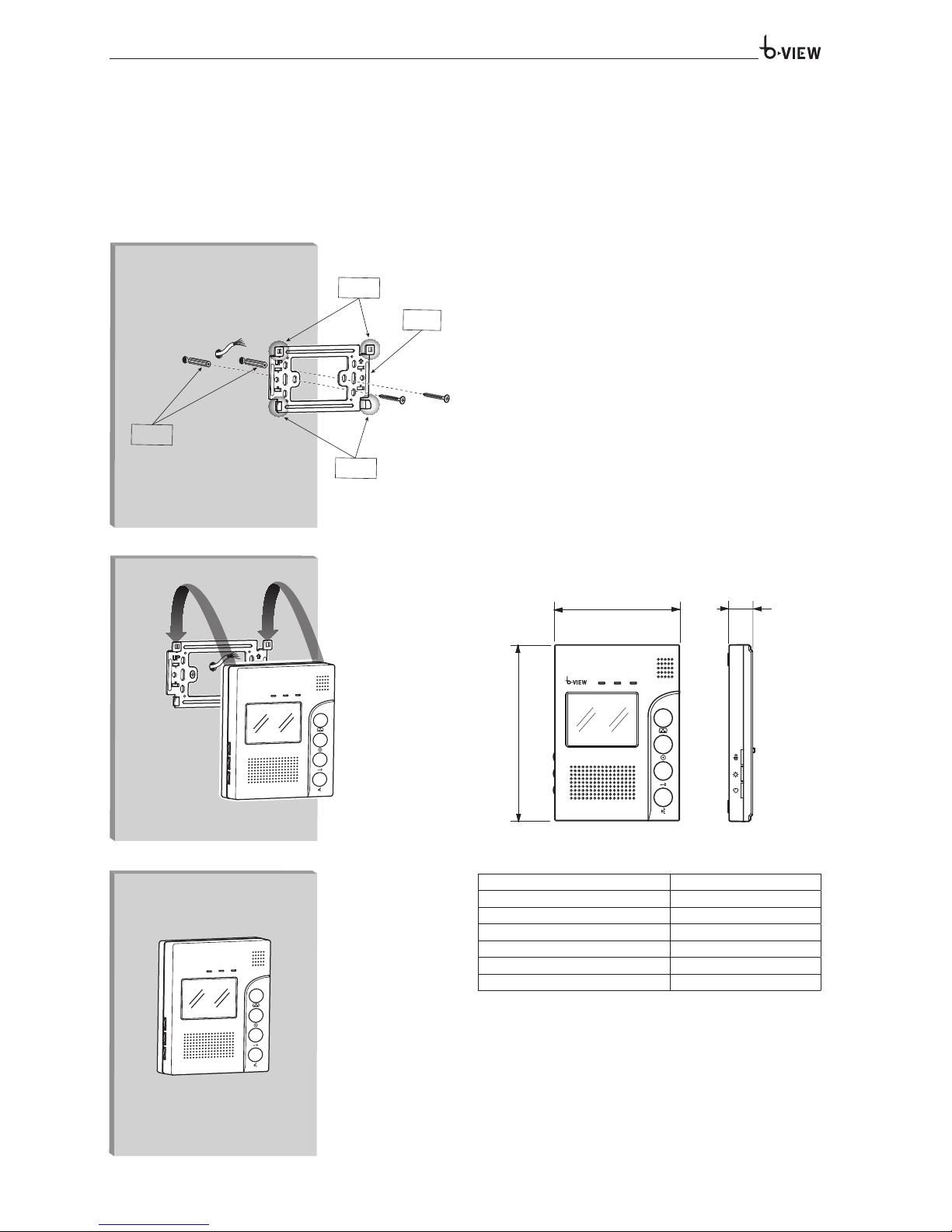
The video receiver is composed of a wall-mounted hands-free unit equipped with a 3,5’’ TFT colour monitor.
The video receiver is composed by :
- push buttons to activate the communication, door lock release, camera preview, intercom call;
- three potentiometers for the communication volume, brightness and chroma adjustments.
INSTALLATION
Consider the unit must be fitted at a suitable height in relation to the user.
Position the location where the unit has to be mounted. Use the bracket to
mark the location point accurately.
Drill the holes and use the screw anchors to fill them. Fasten the metallic
support to the wall using the provided screws and observing the UP indication (figure 1).
According to the wiring diagram, perform the wiring connections.
Mount the unit to the bracket (figure 2).
180
128
24
3
ANCHORS
BRACKET
HOOKS
HOOKS
TECHNICAL FEATURES
Voltage 14.5 VDC
Absorption 400 mA (50 mA stand-by)
Audio mode Duplex
Talking time 2 min
Dimensions 128x180x24 mm
Operating temperature -10 °C +55 °C
Monitor 3.5’’ TFT
A
B
C
VRK01 SA
Page 4

Power supply with plug for connection to the electrical mains and cable with connector for the video receiver connection.
6
J3
CN2
CN1
J1
J2
5
34 2 1
34 2 1
4
TERMINAL BOARDS
CN1-CN2
1
AUDIO (Red)
2 GND (Blue)
3 V+ (Yellow)
4 VIDEO (White)
5 + POWER (
Red
)
6 – POWER GND (
Black
)
CN1 Connected with Entry Panel 1
CN2 Connected with Entry Panel 2
J3 J1
J2
J3 J1
J2
J3 J1
J2
D
JUMPER
J3 (Back light compensation for entry panel call button):
The default setting is with J3 jumper connected. Remove the jumper if the
entry panel button back light is not needed.
J1 (Ringing output):
It is normally supplied inserted. When a call from entry panel to indoor
phone is performed the outdoor panel can also hear the call ring. Remove
jumper J1 to avoid that.
J2 (Video signal compensation):
It is normally supplied inserted. When there are more than one internal
receiver, level J2 jumper connected to the furthest one to assure the video
signal transmission. Remove J2 from the other receivers (see figure 4).
VPSK01 SA
TECHNICAL FEATURES
Main supply 100-240 VAC, 50-60 Hz, 0,4 A
Nominal power supply 14,5 VDC, 1,3 A
Dimensions 105x58x32 mm
Operating temperature 0 °C +40 °C
Page 5
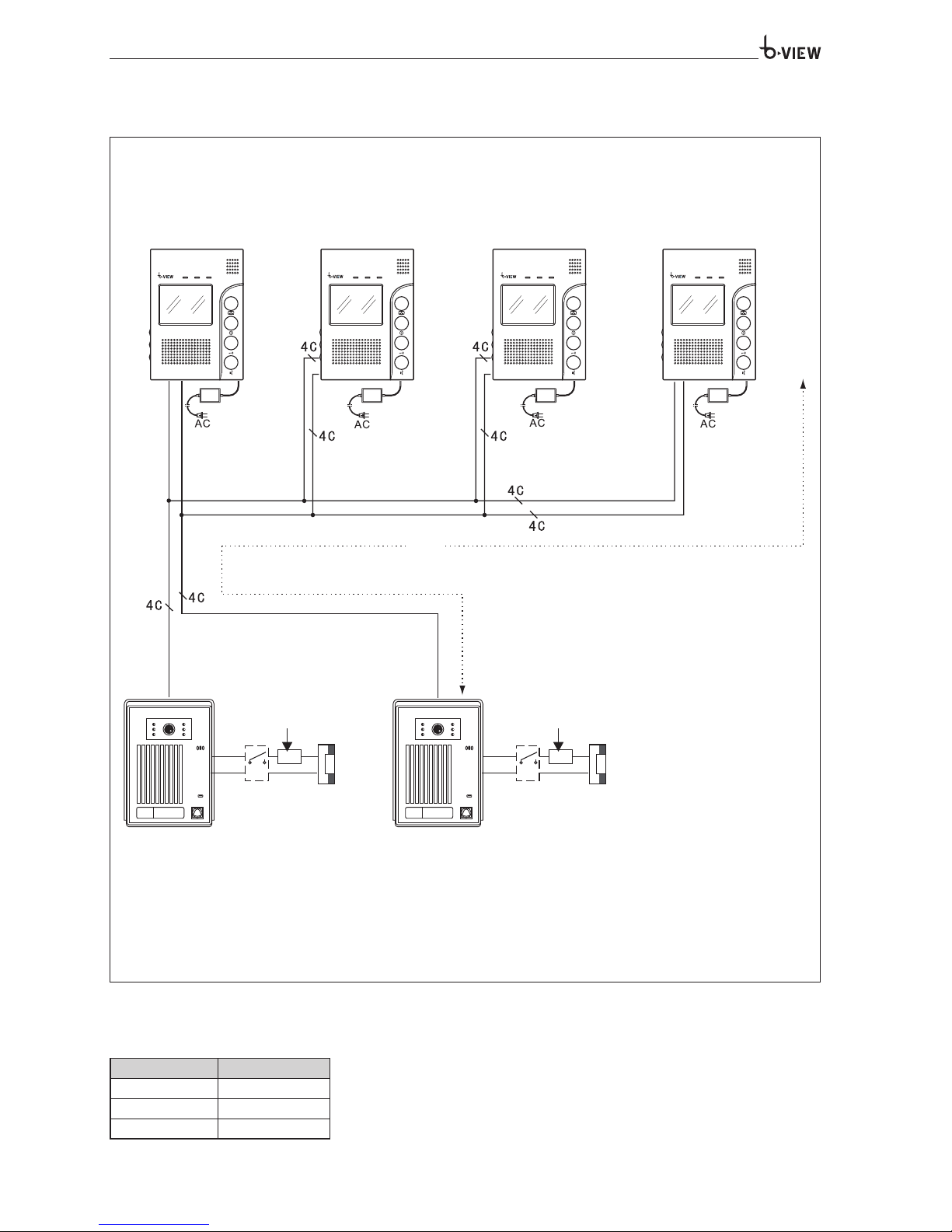
La
Power supply adaptor
AC/DC (included)
Power supply adaptor
AC/DC (included)
Power supply adaptor
AC/DC (included)
Power supply adaptor
AC/DC (included)
Door Lock Door Lock
Power Supply
for lock
Power Supply
for lock
Entry Panel 2Entry Panel 1
Both twisted or untwisted cables are allowed
Distance Wire
La≤ 28 m ≥ 0.2 mm
2
La≤ 50 m ≥ 0.3 mm
2
La≤ 70 m ≥ 0.5 mm
2
CONNECTION EXAMPLES
Maximum extension system
DISTANCES
5
Page 6
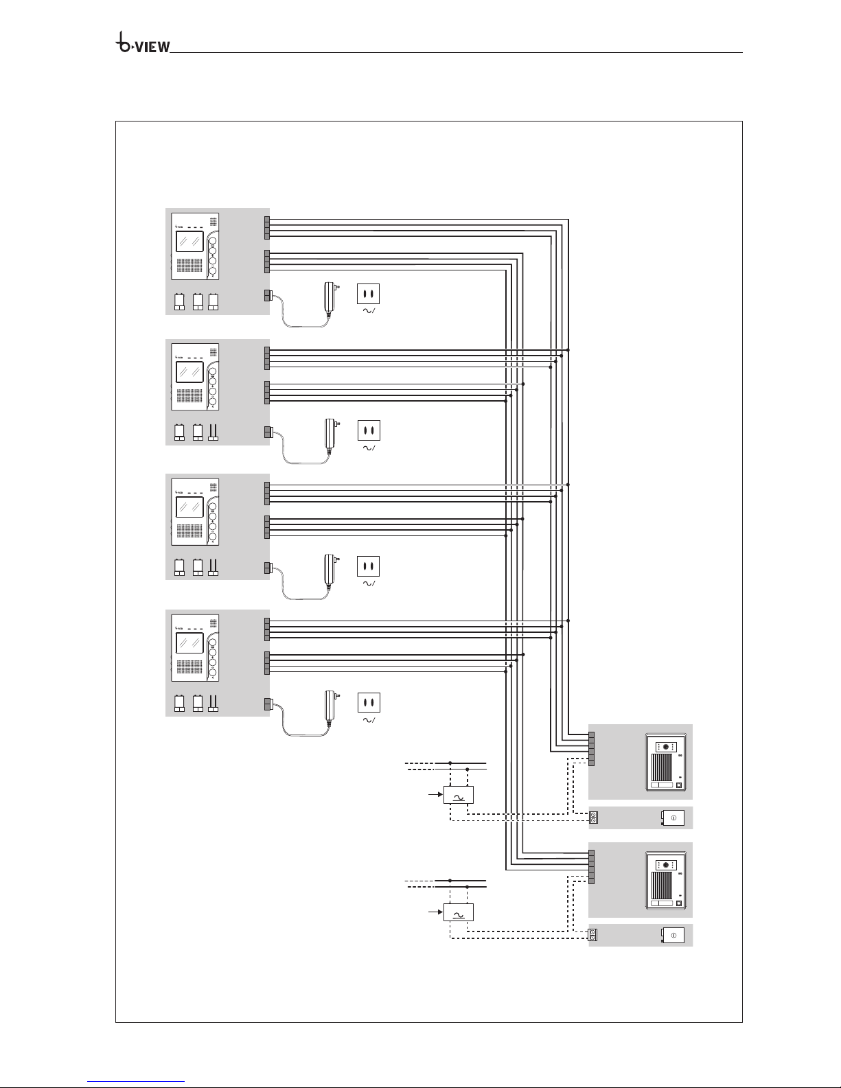
WIRING DIAGRAM
CN1
1
2
3
4
CN2
1
2
3
4
5
6
J3 J1
J2
CN1
1
2
3
4
CN2
1
2
3
4
J3 J1
J2
CN1
1
2
3
4
CN2
1
2
3
4
J3 J1
J2
CN1
1
2
3
4
CN2
1
2
3
4
J3 J1
J2
1 AUDIO
2 GND
3 V+
4 VIDEO
5
5
N
L
N
L
220 V 50Hz
5
6
5
6
5
6
1 AUDIO
2 GND
3 V+
4 VIDEO
5
5
VRK01 SA
VEPK01 SA
VEPK01 SA
VRK01 SA
VRK01 SA
VRK01 SA
Power Supply for Lock
Power Supply for Lock
220 V 50Hz
220 V 50Hz
220 V 50Hz
6
Page 7

7
Page 8

DISPOSAL
Do not litter the environment with packing material: make sure it is disposed of according to the regulations in force in the country where the product is used.
When the equipment reaches the end of its life cycle, take measures to ensure it is not discarded in the environment.
The equipment must be disposed of in compliance with the regulations in force, recycling its component parts wherever possible.
Components that qualify as recyclable waste feature the relevant symbol and the material’s abbreviation.
Imported by TRI-BPT Automation (Pty) Ltd.
http: www.bpt-sa.co.za. – e-mail: [email protected]
 Loading...