

Page 1
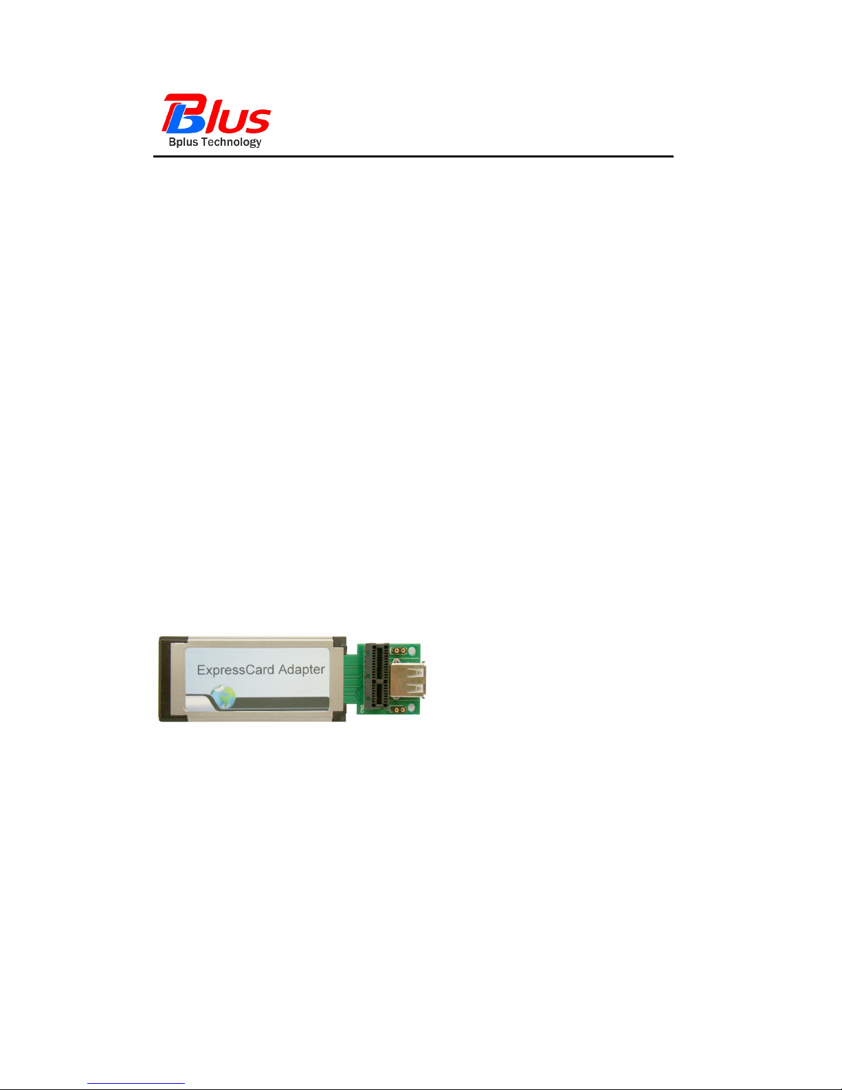
PCI-E and USB to ExpressCard Adapter
User’s Manual
Preliminary
Model: PE3
FAE2009PE3_01
March 2009
Bplus Technology Co., Ltd
5F,NO.63,ZHOU-TZYY ST.,
NEI-HU,TAIPEI,TAIWAN,R.O.C
(+886)2-7721-0550 TEL
(+886)2-8797-4200 FAX
http://www.bplus.com.tw
Page 2

PCI-E and USB to ExpressCard Adapter User’s Manual
Page 1
FAE2009PE3_01 ©2009 Bplus Technology Co., Ltd
CONTENTS
Introduction .............................................................................................................. 2
Interface ..................................................................................................................... 2
Features ..................................................................................................................... 3
Working mode ....................................................................................................... 3
System requirement .......................................................................................... 3
Installation procedure ...................................................................................... 4
Caution ....................................................................................................................... 7
Maintenance ........................................................................................................... 7
Page 3
PCI-E and USB to ExpressCard Adapter User’s Manual
Page 2
FAE2009PE3_01 ©2009 Bplus Technology Co., Ltd
1.0 Introduction
The PCI-E 1x and USB to ExpressCard /34 passive adaptor is a Debug tool for
PCI-E interface card and USB 2.0 devices.
This adapter allows you to use your existing PCI-Express Add-in-Card in the
ExpressCard slot
It's especially designed to save valuable labor and time in the production
environment.
As a powerful tool for engineers, the PCI-E 1x and USB To ExpressCard is
constructed of high Quality components for years of trouble free Service.
2.0 Interface
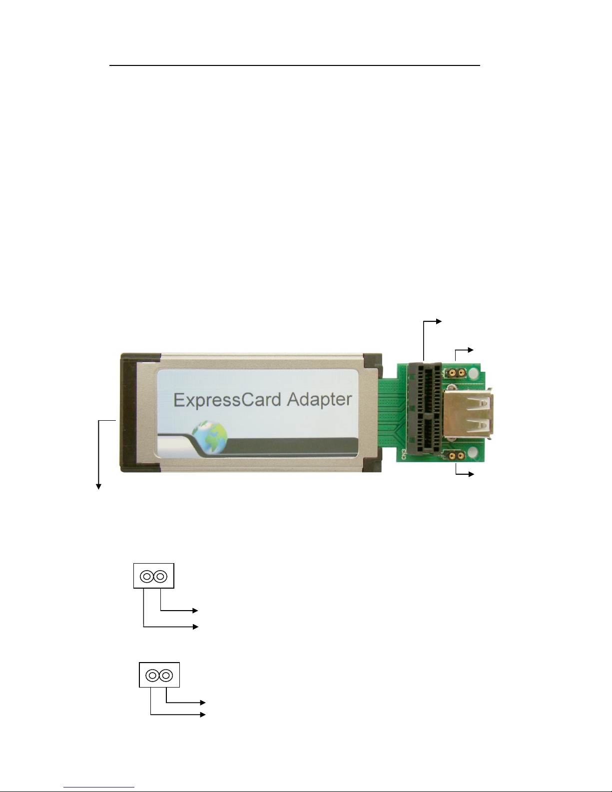
PCI-E and USB to ExpressCard Adapter as shown,
Figure-1 PCI-E and USB to ExpressCard Adapter (heads)
Jump Interface Profile
J1 (GND/+5V) for USB test +5V 600mA Max.
+5V
GND
J2 (GND/+12V) for PCI-E test +12V 200mA Max.
GND
ExpressCard CONN
PCI-E Slot
USB Slot
J2 (GND/+12V)
For PCI-E test
J1 (GND/+5V)
For USB test
12V
J 2
+12V
J 1 5 V
Page 4
PCI-E and USB to ExpressCard Adapter User’s Manual
Page 3
FAE2009PE3_01 ©2009 Bplus Technology Co., Ltd
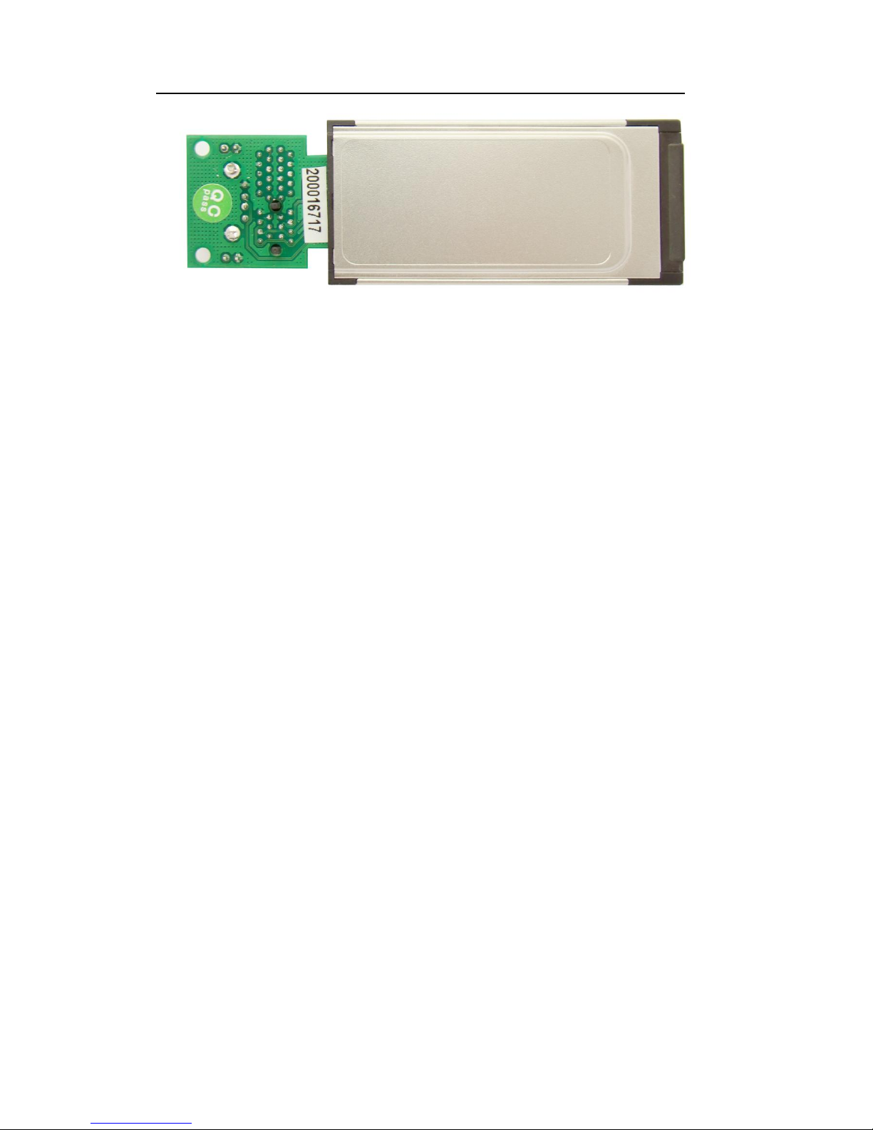
Figure-2 PCI-E and USB to ExpressCard Adapter (back)
3.0 Features
Designed to USB specification vision 2.0 and PCI Express base specification
vision 1.1
Supports PCI-Express Card 1x and USB 2.0 devices
Compliant with multi-system of PC
High quality connectors for long service life
4.0 Working mode
PCI-E and USB to ExpressCard Adapter supports Plug and Play function,
which can convert PCI-E or USB working mode to ExpressCard.
PCI-E to ExpressCard: perform PCI-E function available by
ExpressCard slot
USB to ExpressCard: perform USB function available by ExpressCard
slot
5.0 System requirement
Note book PC and other devices with Express card slot / 34
Windows 2000, XP, Vista, Server2008
Linux
Page 5
PCI-E and USB to ExpressCard Adapter User’s Manual
Page 4
FAE2009PE3_01 ©2009 Bplus Technology Co., Ltd
6.0 Installation procedure
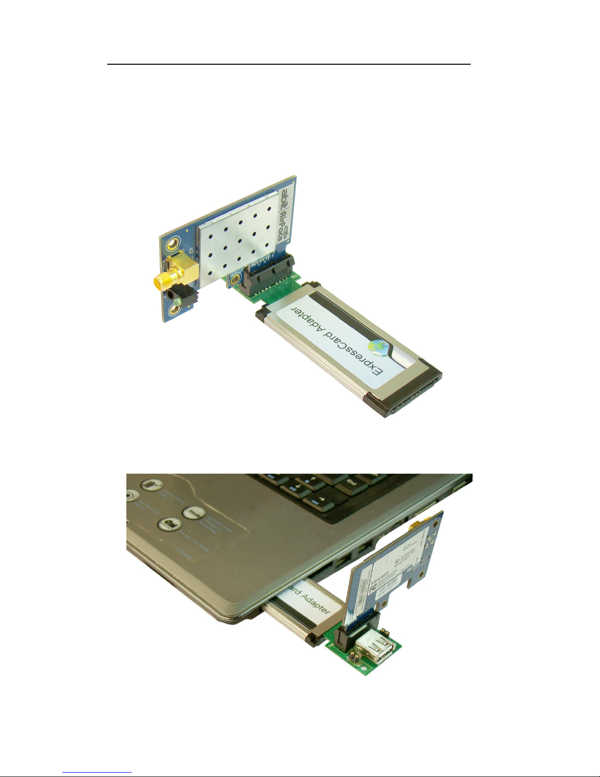
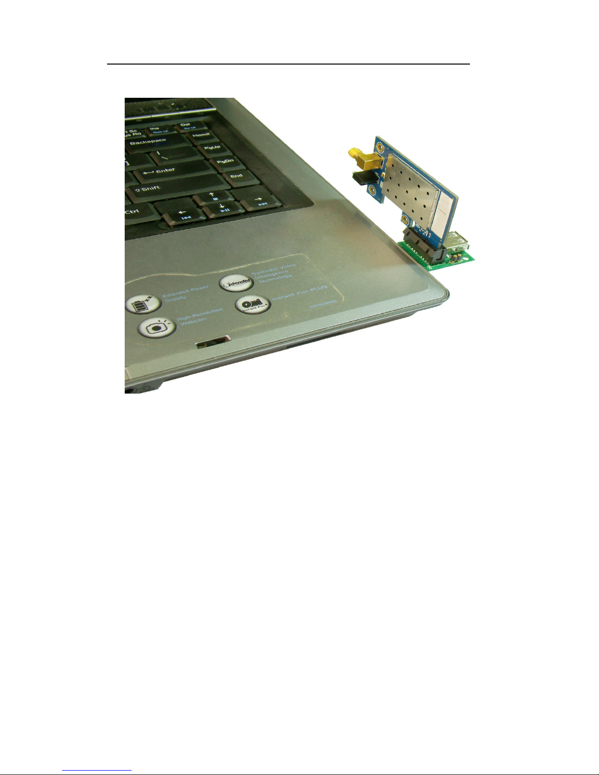
PCI-E to ExpressCard Mode
1) Please plug the device with PCI-E 1×connector into PCI-E slot.
As the following picture shows, the wireless card can be plug into PCI-E 1
×slot.
2) Then, plug all into ExpressCard slot.
Page 6
PCI-E and USB to ExpressCard Adapter User’s Manual
Page 5
FAE2009PE3_01 ©2009 Bplus Technology Co., Ltd
3) Plug into exactly
Page 7
PCI-E and USB to ExpressCard Adapter User’s Manual
Page 6
FAE2009PE3_01 ©2009 Bplus Technology Co., Ltd
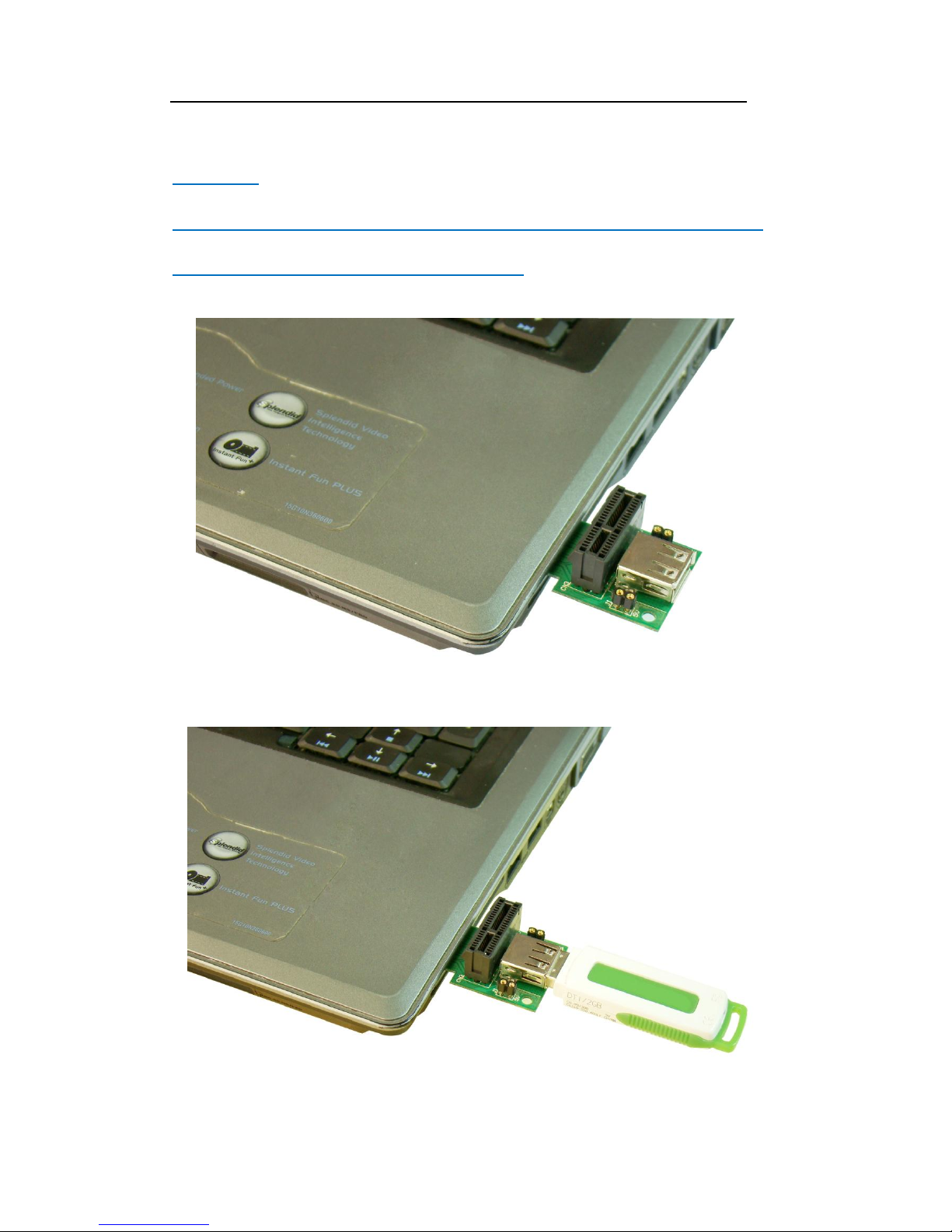
USB to ExpressCard Mode
Attention:
The device with USB connector supports Plug and Play function.
User can plug it into USB slot directly.
1) Please plug PCI-E and USB to ExpressCard Adapter into ExpressCard slot
2) Then, plug the device with USB connector into USB slot
Page 8

PCI-E and USB to ExpressCard Adapter User’s Manual
Page 7
FAE2009PE3_01 ©2009 Bplus Technology Co., Ltd
7.0 Caution
The device which holds PCI-E connector DOES NOT support Plug and
Play function. DO NOT deal with it when energized.
Jump J1 includes +5V and GND two signals for USB test. The Max. Load
current is less than 600mA. << Warning: Do NOT short these two
pins
Jump J2 includes +12V and GND for PCI-E test. The Max. Load current is
less than 200mA. << Warning: Do NOT short these two pins
All products specifications are subject to change without notice.
Aeneas reserves the right to modify the products in its line during the
course of the year.
8.0 Maintenance
There is no guarantee for incorrect operation. (Please check Caution Terms)
Please contact the distributer for more details.
 Loading...