

Page 1
Mini PCI-E to PCI-E Adapter
User’s Manual
Preliminary
Model: MP2A
FAE2009MP2A_03
June 2009
Bplus Technology Co., Ltd.
5F, No.63, Zhou-Tzyy St., Nei-Hu,
Taipei, Taiwan
(886-2)77210550 TEL
(866-2)87974200 FAX
http://www.Bplus.com.tw
Page 2

Mini PCI-E to PCI-E Adapter User’s Manual
Page 1
FAE2009MP2A_03 ©2009 Bplus Technology
CONTENTS
Introduction ............................................................................................................ 2
Interface ................................................................................................................... 2
Features .................................................................................................................. 5
Package contents ............................................................................................. 6
System requirement ........................................................................................ 7
Installation procedure..................................................................................... 7
Caution ................................................................................................................... 15
Maintenance ....................................................................................................... 15
Page 3
Mini PCI-E to PCI-E Adapter User’s Manual
Page 2
FAE2009MP2A_03 ©2009 Bplus Technology
1.0 Introduction
The MP2A passive adapter is designed for desktop PCs that convert Mini-Card
to USB port or standard PCI-Express 1x slot.
You can insert your USB type minicard to this adapter then plug to USB port
through USB cable.
Or insert your PCI-E type mini-card into this adapter then insert to PCI-E 1x
connector.
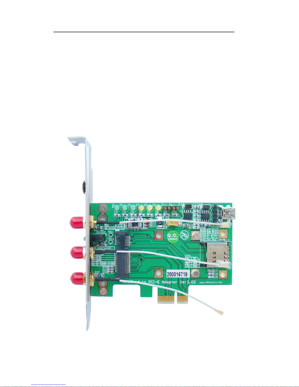
2.0 Interface
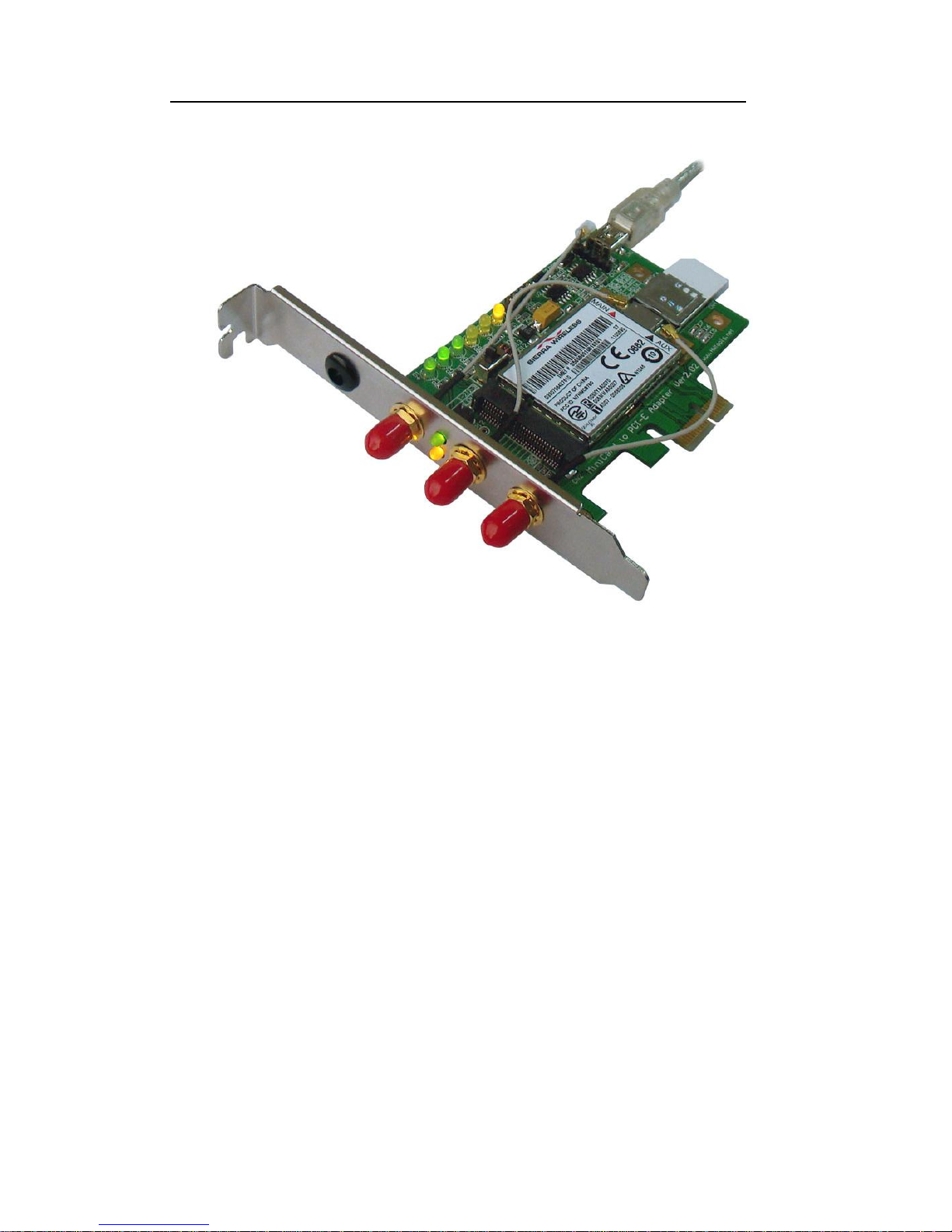
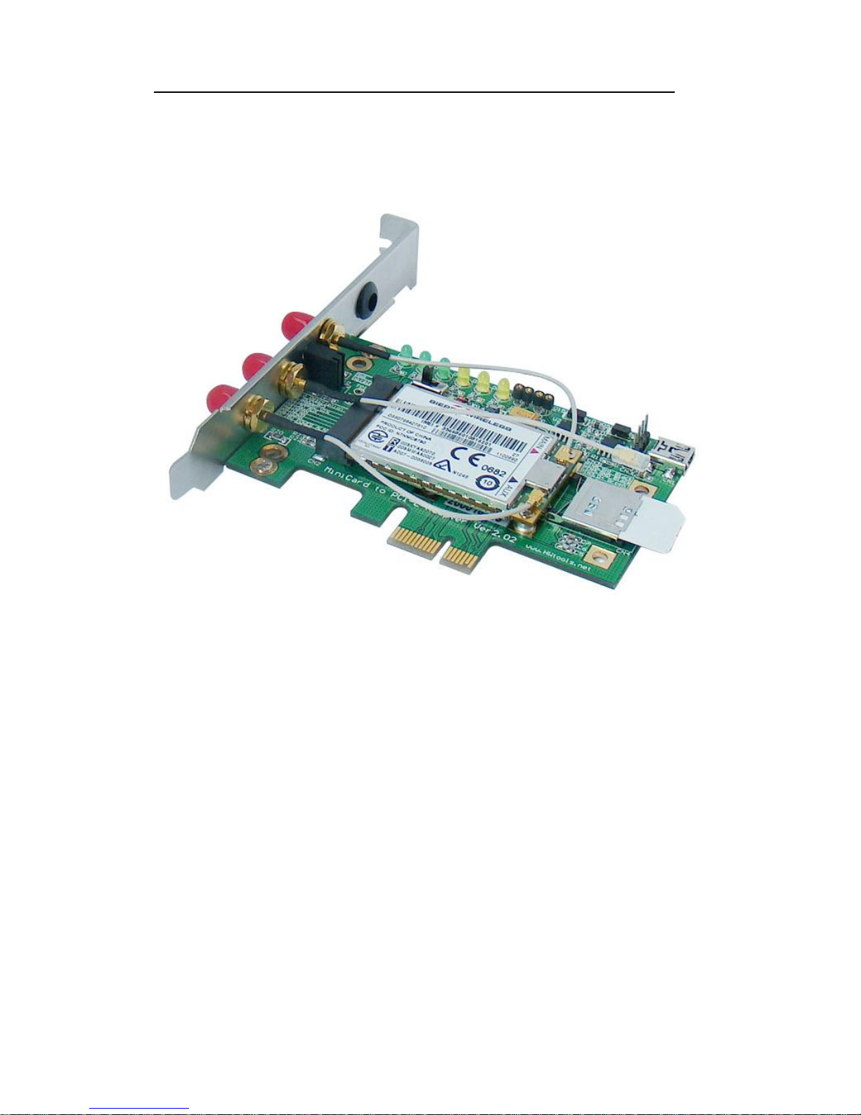
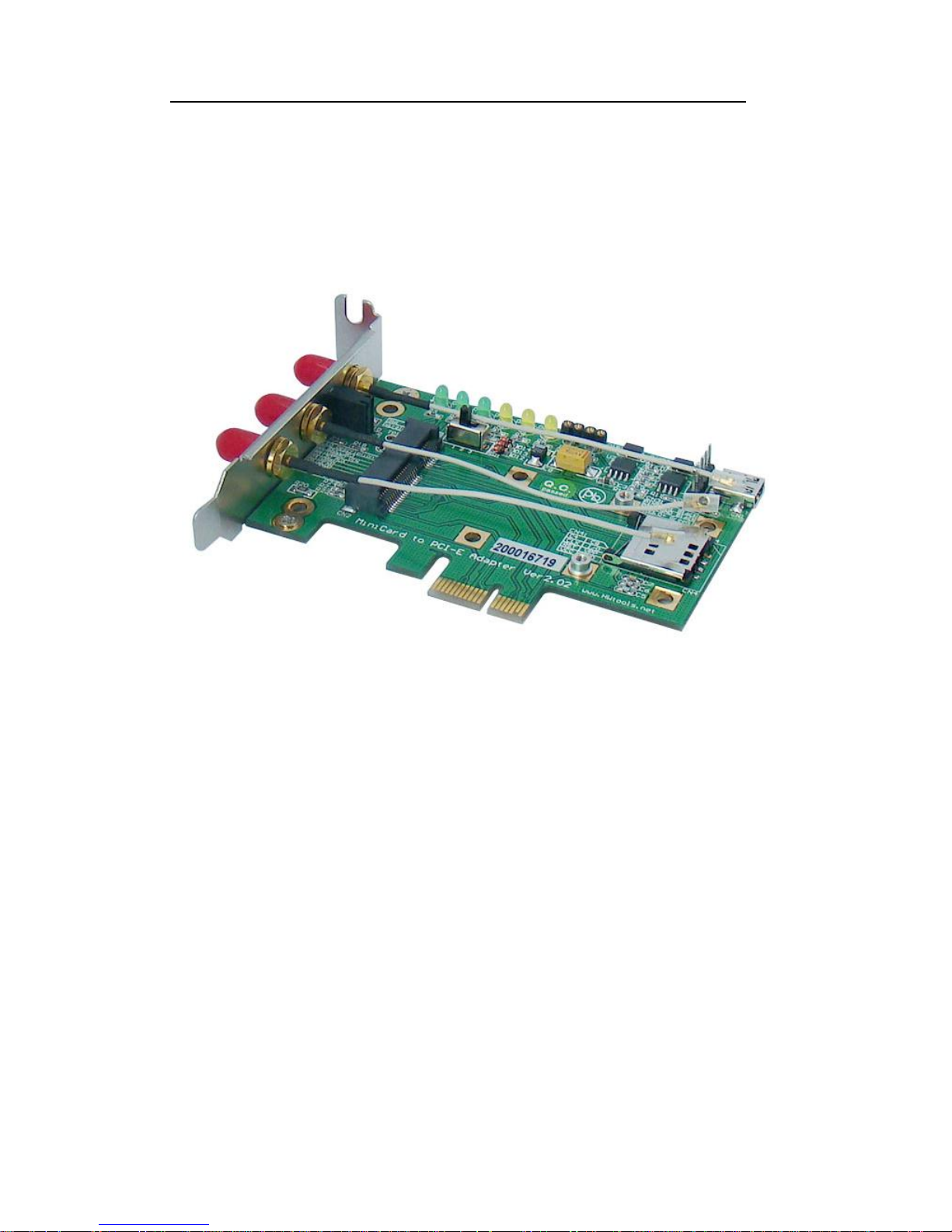
Mini PCI-E to PCI-E Adapter as shown,
Figure-1 Mini PCI-E to PCI-E Adapter (heads)
Page 4
Mini PCI-E to PCI-E Adapter User’s Manual
Page 3
FAE2009MP2A_03 ©2009 Bplus Technology
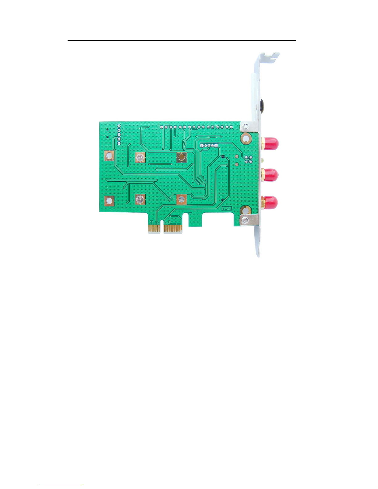
Figure-2 Mini PCI-E to PCI-E Adapter (back)
LED State:
1. D4(LED Green)
When PC is in energetic status and not turn on, plug MP2A into PCIE slot of
MB. Now, if D4 is on, it shows normal working status. If not, the user needs to
check the PCI-E slot and MB ok or not.
2. When the user plugs MP2A into PCI-E slot and turn on the pc, LED D1,D3
and D10 are all on. If not, it shows the power is not normal.
3. When the user plugs MP2A into MB through USB cable line and turn on the
pc, LED (Green) D1, D2, D3 and D10 are all on. If not, it shows the power is
not normal.
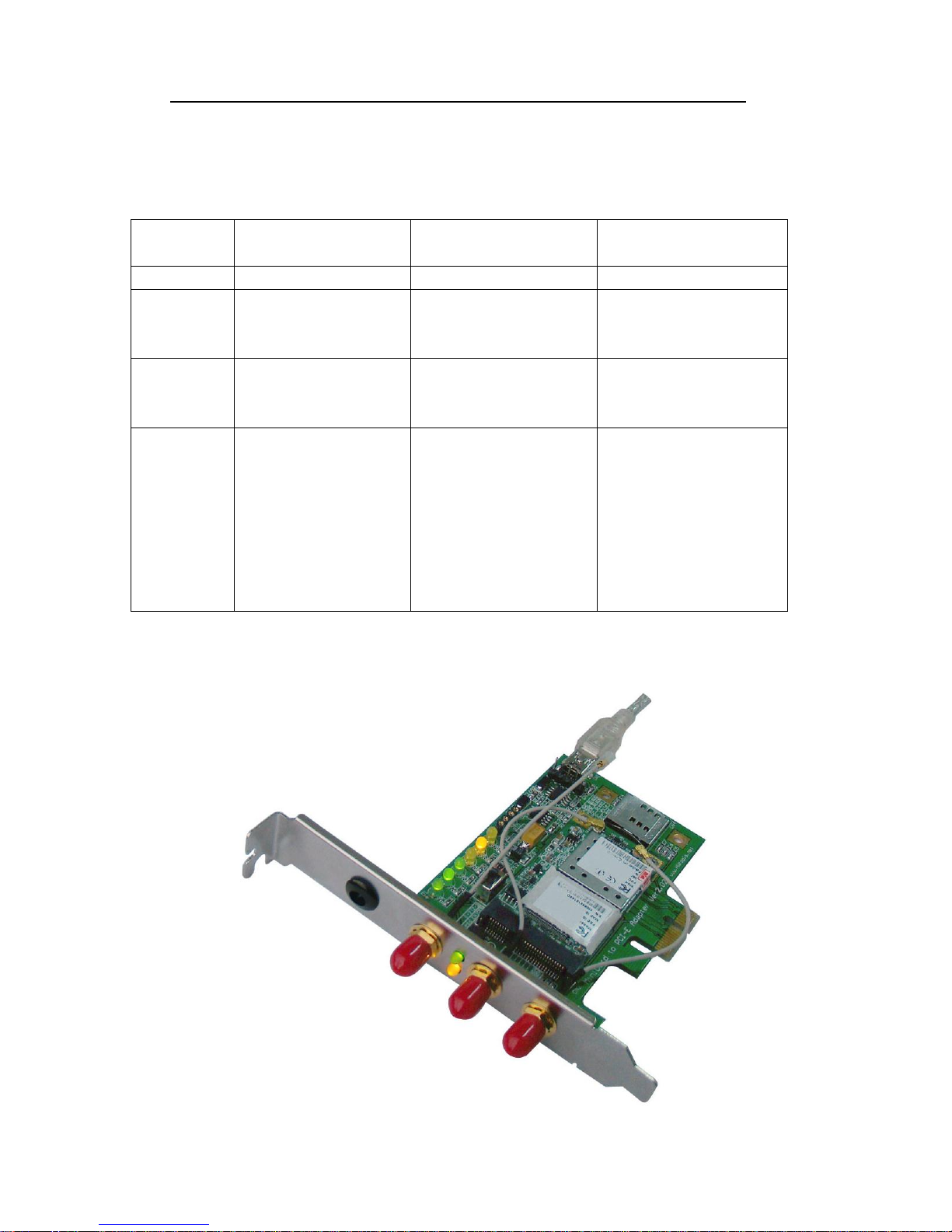
4. When the user plugs mini PCI-E card into MP2A and turn on the pc, LED
Page 5
Mini PCI-E to PCI-E Adapter User’s Manual
Page 4
FAE2009MP2A_03 ©2009 Bplus Technology
(Yellow) D11, D4, D5 and D6 will show different light status. Please
reference the below table,
TABLE1: Recommended Use for LED Indicators by Wireless Classes
LED state
D4, D11(W-PAN)
D5, D11(W-LAN)
D6,D11(W-WAN)
OFF
Not powered
Not powered
Not powered
ON
Powered; ready to
transmit or receive
Powered, associated, and
authenticated but not
transmitting or receiving
Powered, associated, and
authenticated but not
transmitting or receiving
Slow Blink
N/A
Powered but not
associated or
authenticated; searching
Powered but not
associated or
authenticated; searching
Intermittent
Blink
Activity proportional to
transmitting/receiving
speed
Activity proportional to
transmitting/receiving
speed
Activity proportional to
transmitting/receiving
speed
For voice applications,
turning off and on the
intermittent blink based
on the ring pulse cycle
can indicate a ring event
D5, D11 (W-LAN)
Page 6
Mini PCI-E to PCI-E Adapter User’s Manual
Page 5
FAE2009MP2A_03 ©2009 Bplus Technology
D6, D11 (W-WAN)
3.0 Features
Allow user to test PCI Express Mini modules with the PCI Express slot or USB
port.
Supports two primary system bus interface includes PCI Express and USB.
Support all of Mini-Cards such as SSD, Turbo memory, 3G, CDMA, WLAN,
WWLAN,
HSPA MODEM Mini Card to desktop PC.
Support SIM card connector.
Page 7
Mini PCI-E to PCI-E Adapter User’s Manual
Page 6
FAE2009MP2A_03 ©2009 Bplus Technology
4.0 Package contents
Mini PCI-E / PCI-E adapter x1
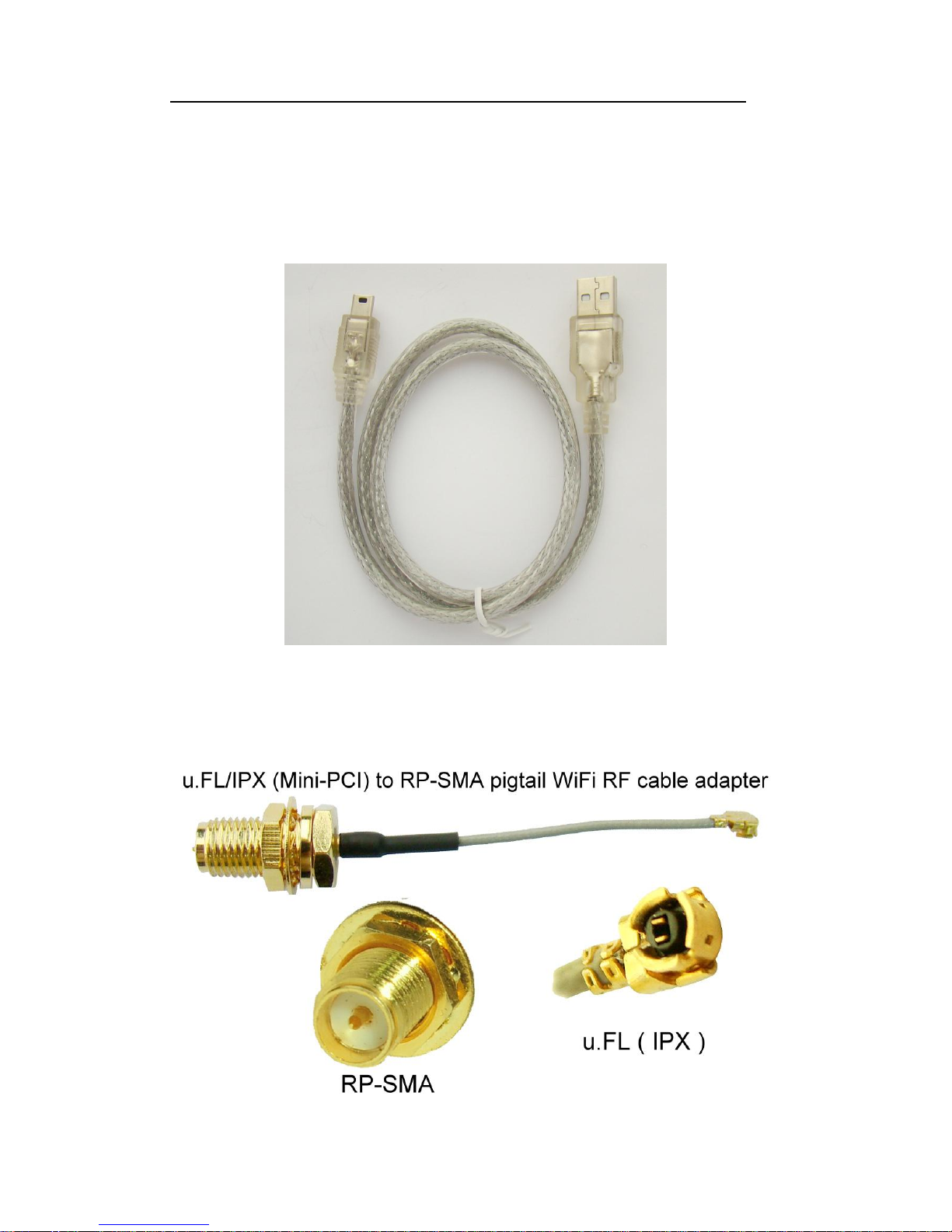
Accessory: USB cable x1
Accessory: IPX to RP-SMA cable x3
Page 8
Mini PCI-E to PCI-E Adapter User’s Manual
Page 7
FAE2009MP2A_03 ©2009 Bplus Technology
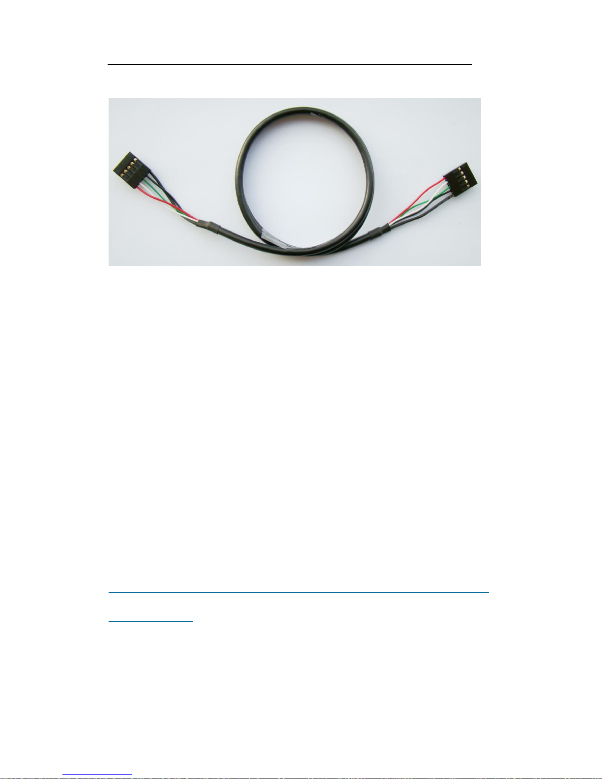
USB DuPont 5PIN to DuPont 5PIN cable x1
Low profile PCI express bracket x1
Standard Height PCI express bracket x1(Default)
5.0 System requirement
PCI-Express 1x slot or USB port
Windows 2000, XP, Vista 32/64
Linux
6.0 Installation procedure
MP2A supports two kinds of cards, which includes Half-Mini Card,
Full-Mini Card.
Page 9
Mini PCI-E to PCI-E Adapter User’s Manual
Page 8
FAE2009MP2A_03 ©2009 Bplus Technology
Desktop PC Application _ Wireless LAN Card
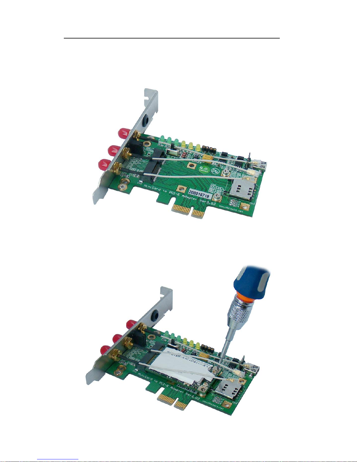
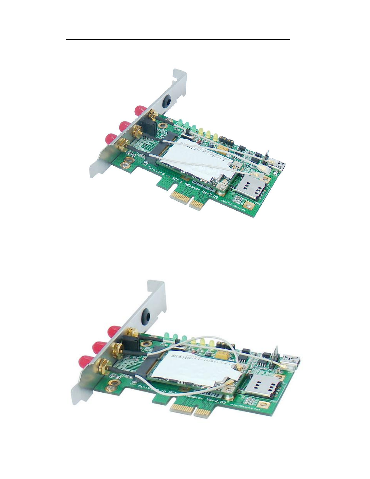
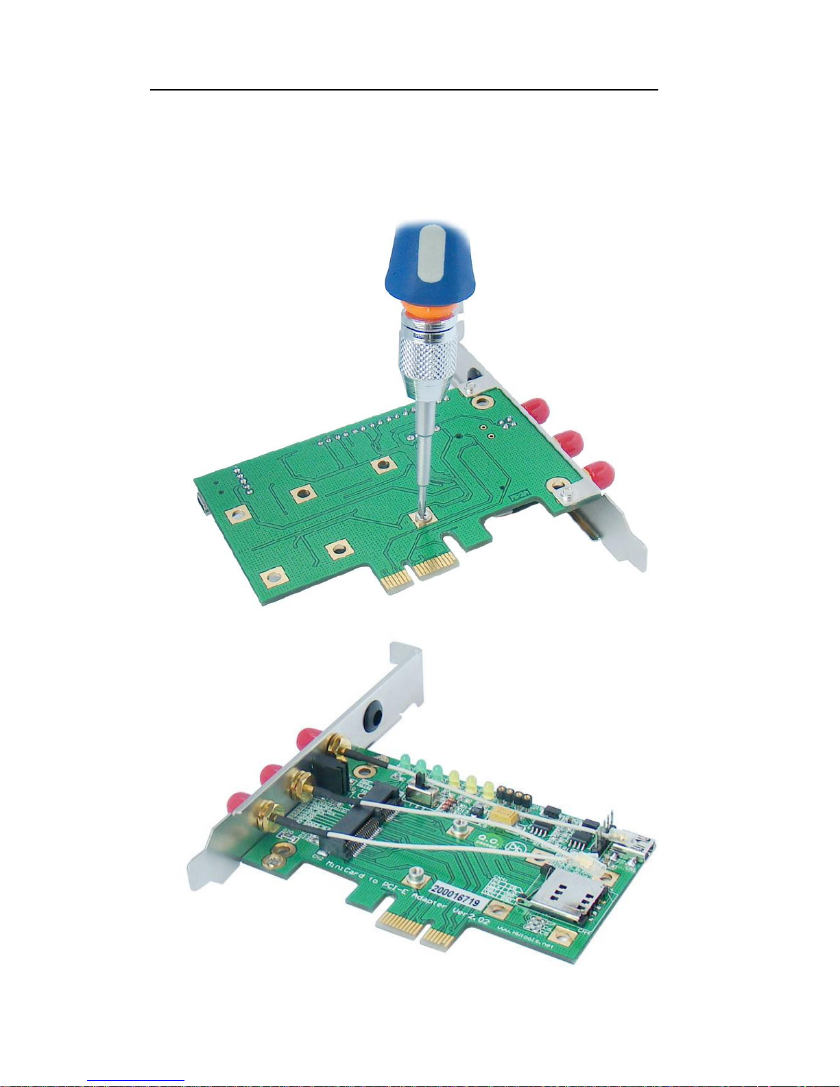
1) Remove the caps on the two posts,
2) Plug mini card device such as wireless LAN card into mini PCI-E connector.
The other side should be fixed by two screws.
Page 10
Mini PCI-E to PCI-E Adapter User’s Manual
Page 9
FAE2009MP2A_03 ©2009 Bplus Technology
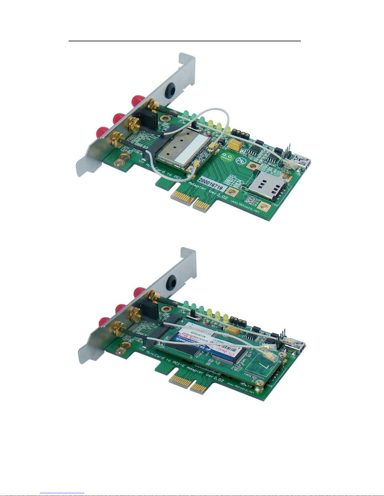
3) Please ensure fix the antenna IPX CONN on mini card exactly.
4) Put the wireless antenna on the RP-SMA CONN.
Page 11
Mini PCI-E to PCI-E Adapter User’s Manual
Page 10
FAE2009MP2A_03 ©2009 Bplus Technology
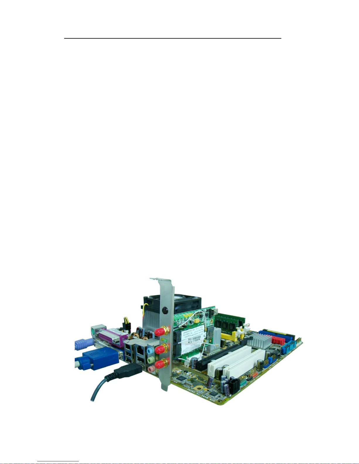
5) Before the user plugs PCI-E connector into PC M/B, please ensure cut off
the PC power firstly, then continue plug-in. Finally, please ensure USB
cable line or DuPont 5P to 5P cable line connect OK.
For other kind of card, the user needs to change the post position
Page 12
Mini PCI-E to PCI-E Adapter User’s Manual
Page 11
FAE2009MP2A_03 ©2009 Bplus Technology
Page 13
Mini PCI-E to PCI-E Adapter User’s Manual
Page 12
FAE2009MP2A_03 ©2009 Bplus Technology
Attention:
1. Do not deal with it when energized, incorrect approach will
lead to product damage.
2. Accessories include ONE pcs USB cable line and ONE pcs
DuPont 5P to 5P cable line. They CANNOT be used at the
same time.
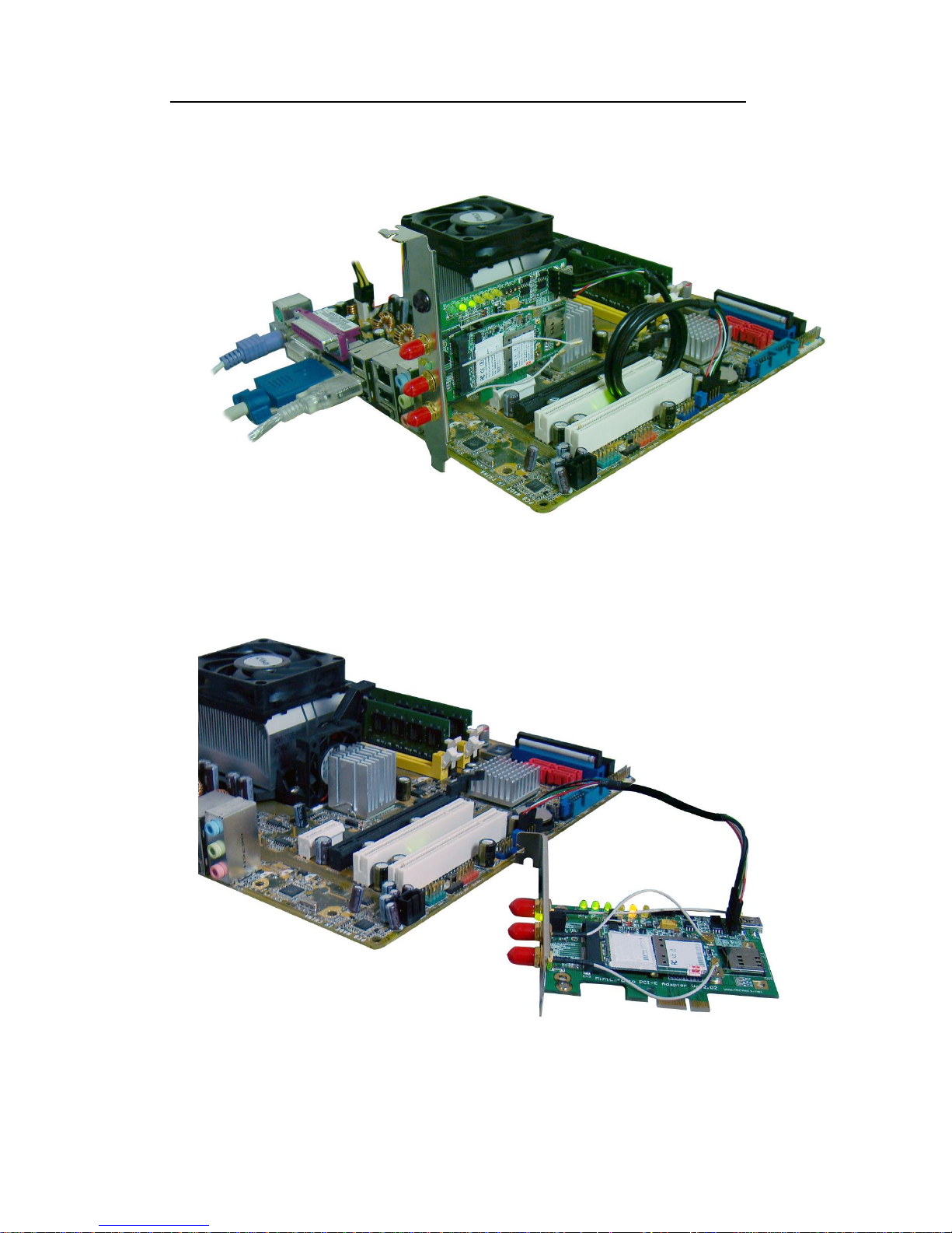
3. The support style of mini card decides the installation
position for MP2A. If your card supports PCI-E mode,
please plug MP2A into PCI-E slot. Or it supports USB mode,
then MP2A should be connected by cable line rather than
PCI-E slot connect.
PCI-E Mode
Page 14
Mini PCI-E to PCI-E Adapter User’s Manual
Page 13
FAE2009MP2A_03 ©2009 Bplus Technology
Mixed Mode
USB Mode
Page 15
Mini PCI-E to PCI-E Adapter User’s Manual
Page 14
FAE2009MP2A_03 ©2009 Bplus Technology
Desktop PC Application _ 3G SIM Card
1. Plug 3G SIM card into SIM slot.
2. Install HSDPA module of Mini PCI-E slot ok and fix antenna ok.
3. Before plug MP2A into PCI-E slot, please ensure cut off the PC power firstly.
Then, connect USB cable line or DuPont 5P to 5P cable line ok.
Attention:
1. Do not deal with it when energized, incorrect approach will
lead to product damage.
2. Accessories include ONE pcs USB cable line and ONE pcs
DuPont 5P to 5P cable line. They CANNOT be used at the
same time.
3. It performs successfully by running HSDPA module
Page 16
Mini PCI-E to PCI-E Adapter User’s Manual
Page 15
FAE2009MP2A_03 ©2009 Bplus Technology
program.
Also, we provide the other kind of bracket. The Low profile PCI Express
bracket may fix your small PC M/B.
7.0 Caution
Before PCI-E mode performs, please cut off the PC power, also as the same to
the remove. The incorrect action will lead to product damage.
All products specifications are subject to change without notice.
Bplus reserves the right to modify the products in its line during the course of
the year.
8.0 Maintenance
There is no guarantee while PC power is on and MP2A is been removing.
Please contact the distributer for more details.
 Loading...