

Page 1
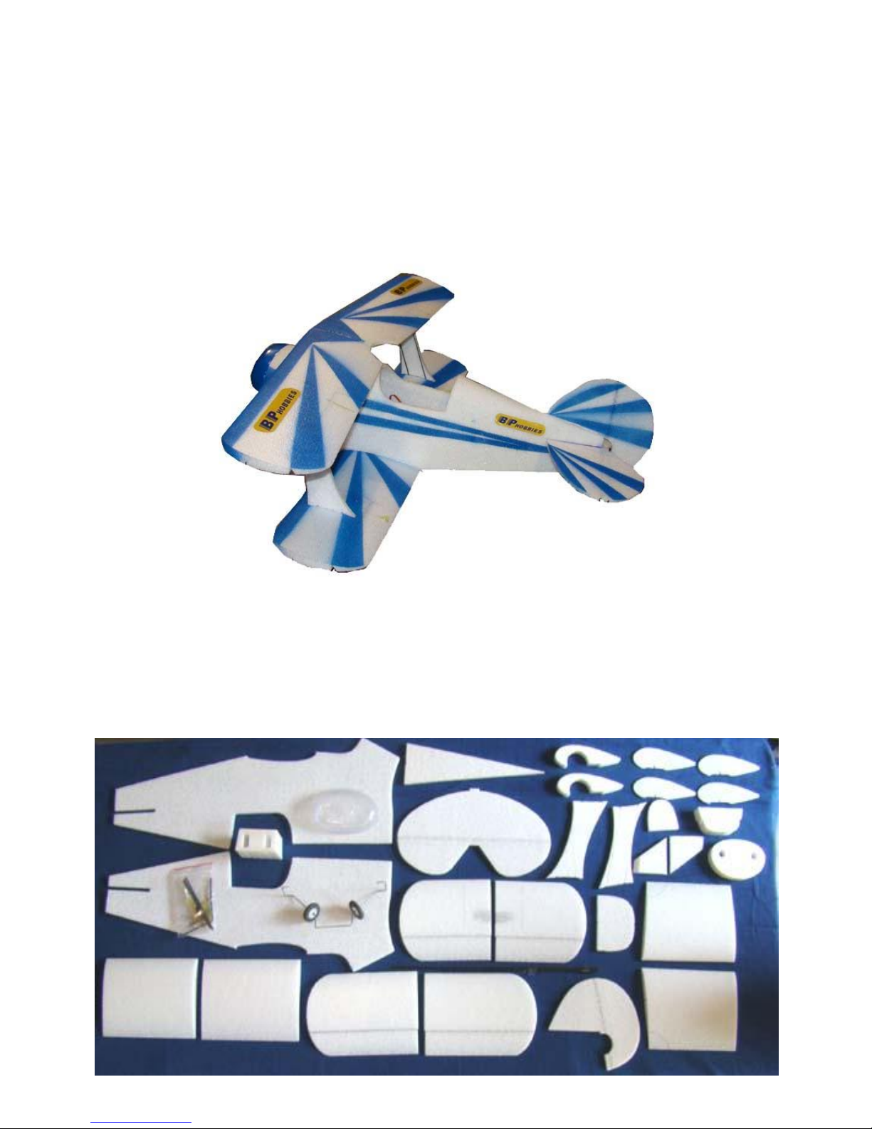
E-AERO EPP PITTS KIT
From
BP HOBBIES
Parts Included in kit
Page 2

Thank you for purchasing the BP Hobbies/E-aero EPP Pitts. Please take the time to read through the
instruction manual before beginning the build. If you have had little or no experience working with EPP
foam it requires some patience to work with it. Although the Pitts is not hard to build, it is certainly
different than building a balsa or EPS foam plane. A few things about EPP foam. There are only a few
glues that will stick to EPP. Regular CA, thin, medium and thick will stick well when used with
accelerator. Hot melt glue sticks well but can not be left in a hot car as the high heat will soften the glue.
Epoxies, white glue and foam safe CA do not work on EPP foam. Put a brand new sharp blade in your
hobby knife. Dull knives do not work well with EPP foam. To paint the Pitts we used Krylon brand
indoor/outdoor spray paint and stencils made from card stock.
You will need these additional items to complete the kit.
2oz bottle of medium CA
2oz bottle of thin CA
4oz bottle of accelerator
Hot melt glue gun
Sharp hobby knife
4- 9 gram servos
4 channel receiver
BPA 2212-10 motor
1- 1800mah 11.1 volt lipo battery
1- BP 18A amp speed controller
Heat gun
Clear duct tape
2 packages of DuBro part # 845 mini E/Z connector.
8x6 APC propeller
8 inch Y connector
Velcro
Spray paint
Page 3
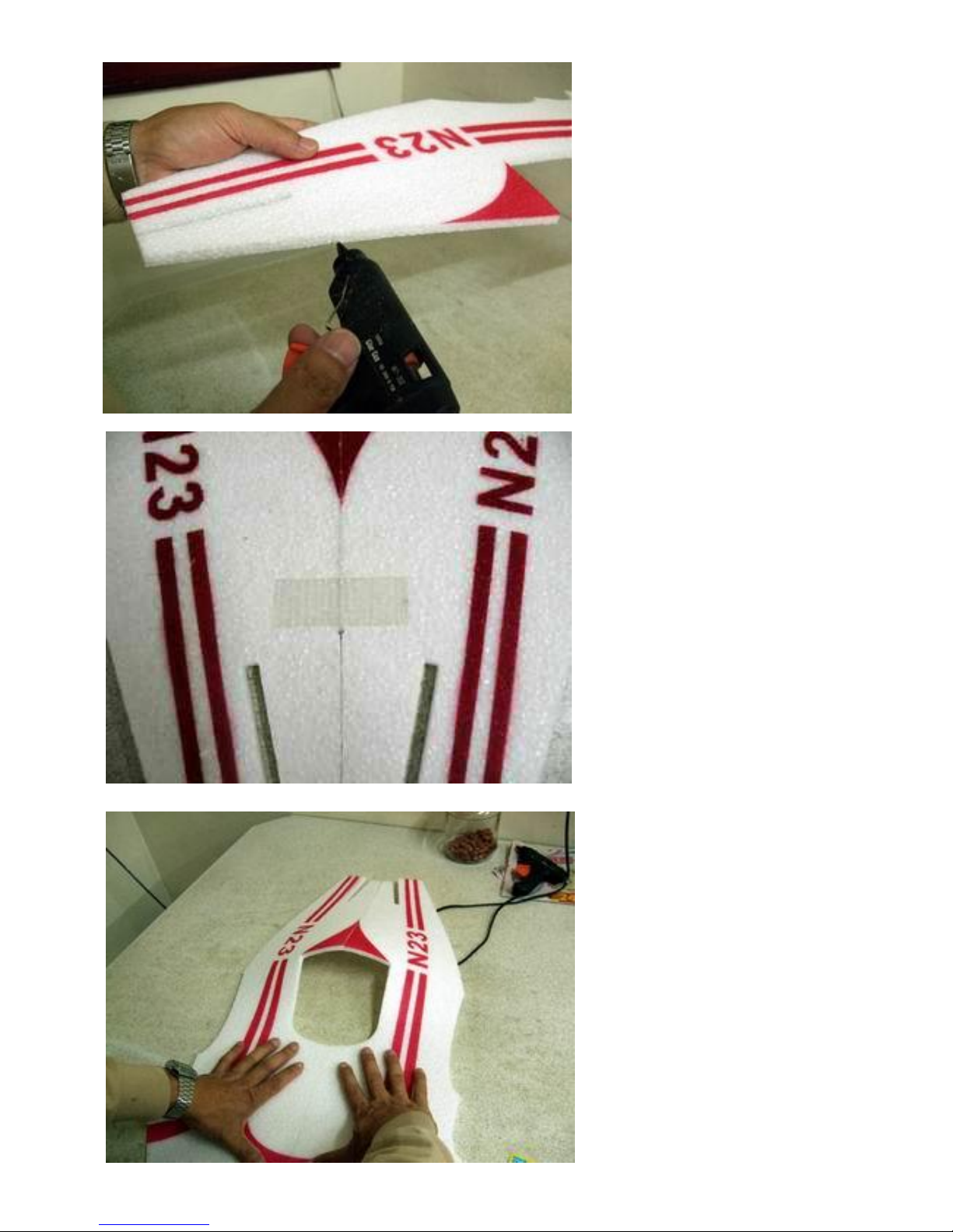
Step 1
Using hot melt glue or medium CA
glue the rear top section of the fuse
together. If you are using hot melt
glue do not leave the airplane in a hot
car for long periods of time. The heat
will soften the hot glue causing a
glue failure at the joint. I prefer to
use medium CA and accelerator.
Step 2
Hold the two halves together with
tape until the glue sets.
Step 3
Glue the front top section of the fuse
together using medium CA and
kicker.
Page 4
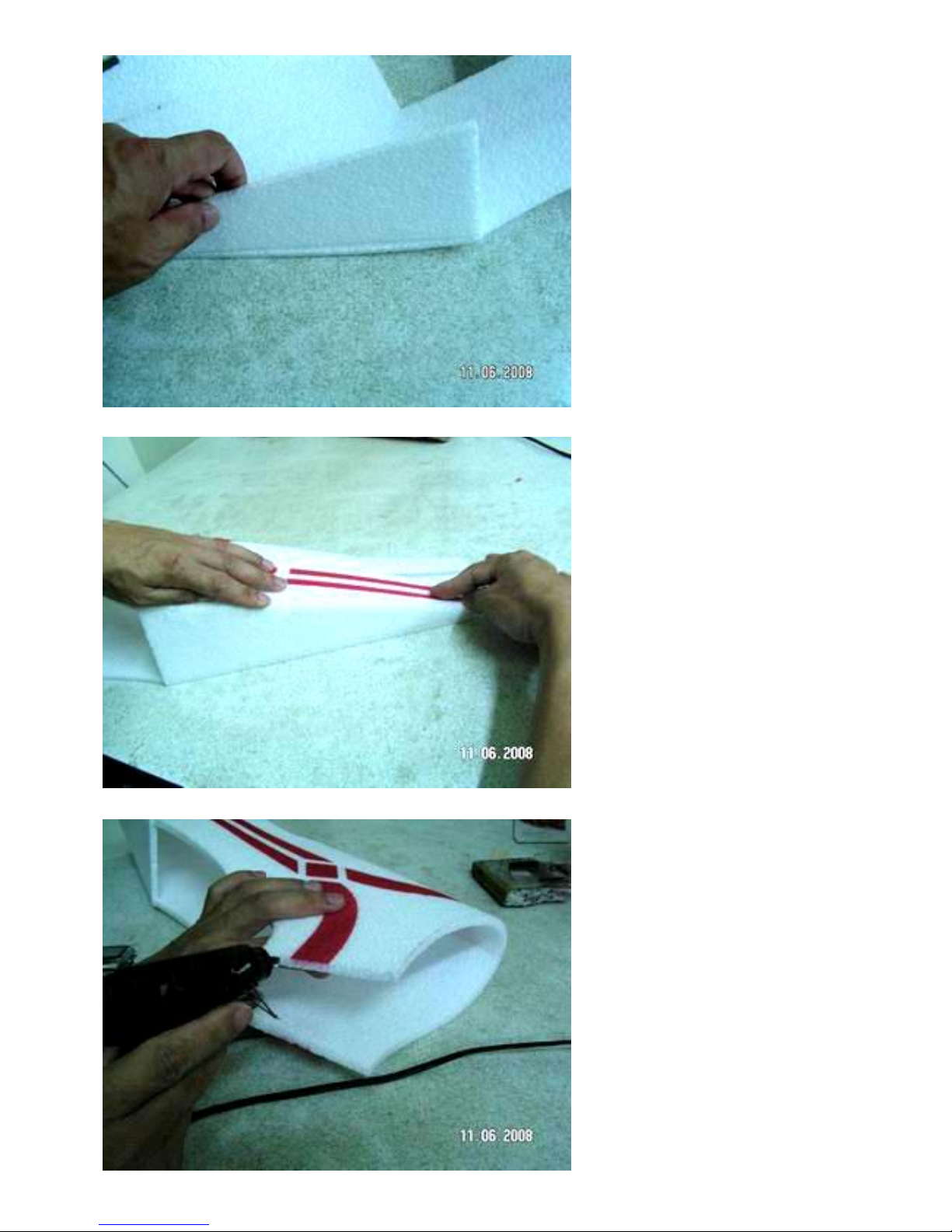
Step 4
Using medium CA glue the fuse rear
bottom section to one of the sides
making sure that there is a 90 degree
angle between the side and the
bottom.
Step 5
Glue the other fuse side to the rear
bottom piece.
Step 6
Glue the lower front fuse sides
together.
Page 5
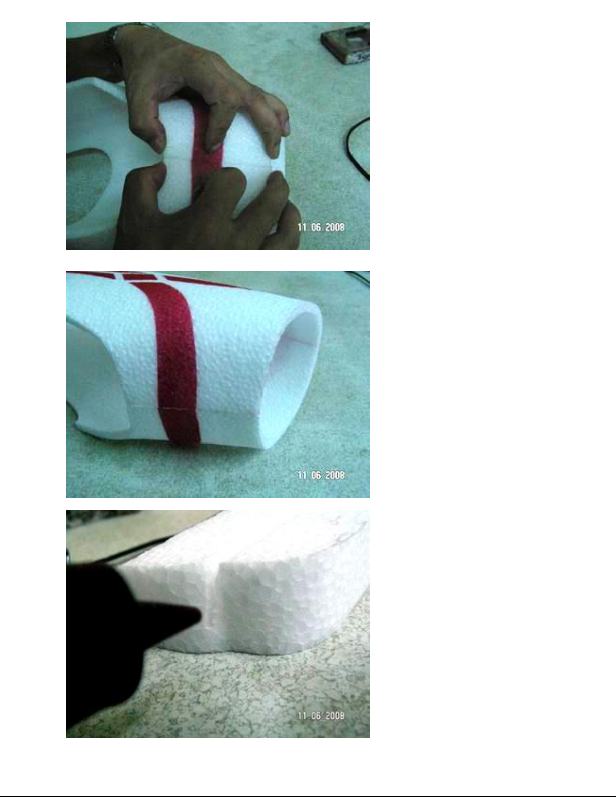
Step 7
Use a little force to pull the two sides
together and hold until the glue sets.
Step 8
It should look like this when
completed.
Step 9
Using ONLY hot melt glue apply a
good amount of it in the grove where
the landing gear wire will be
installed.
Page 6
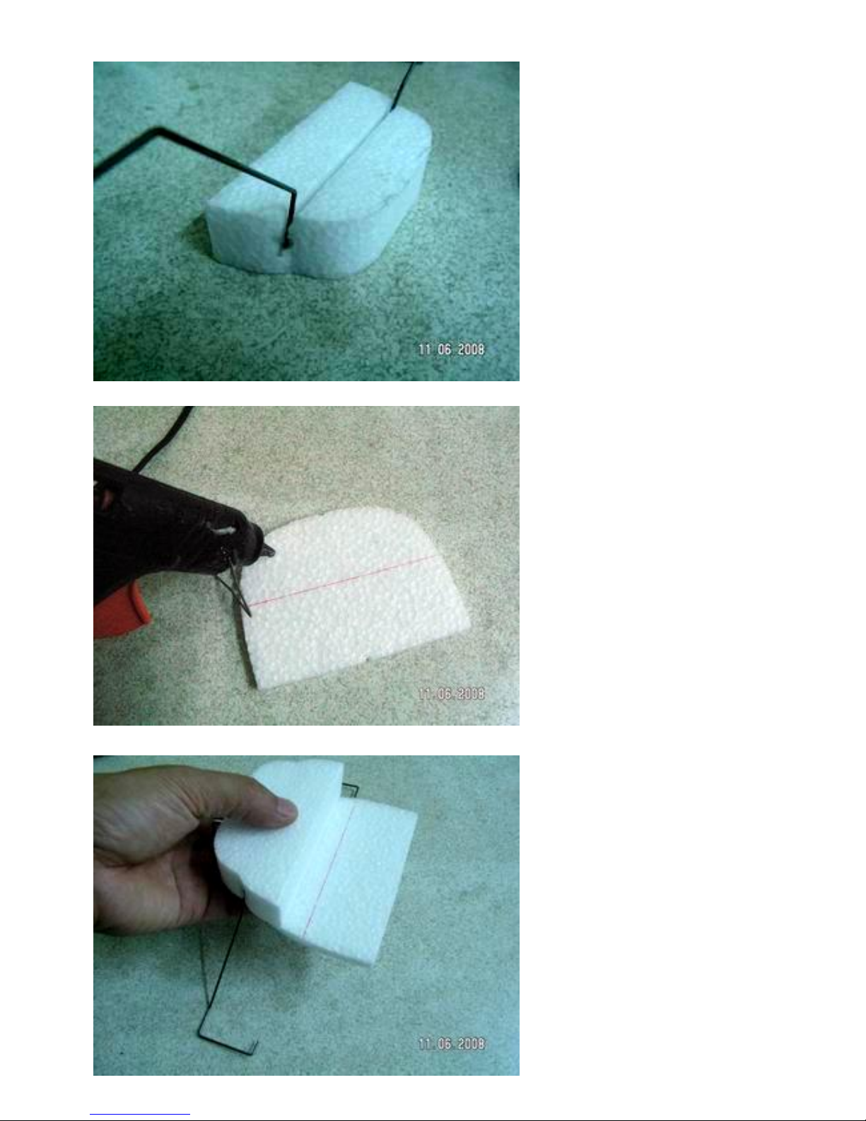
Step 10
While the glue is hot force the
landing gear wire into the slot.
Hold the wire in place until the glue
sets.
Step 11
Apply hot melt glue to the landing
gear cover. There are small notches
in the foam piece to aid you in
positioning the two pieces.
Step 12
Put the two pieces together and hold
them until the glue sets.
Page 7
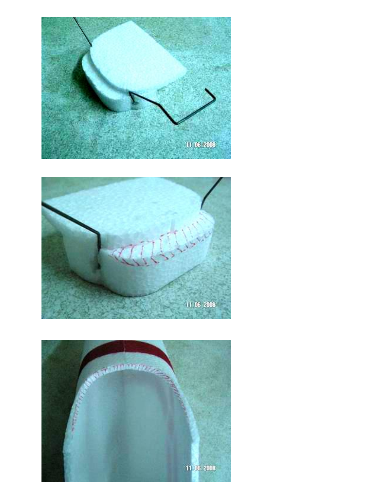
This is what it should look like when
finished.
Step 13
Bevel the shaded area with a hobby
knife.
Step 14
Bevel the shaded area with a hobby
knife
Page 8
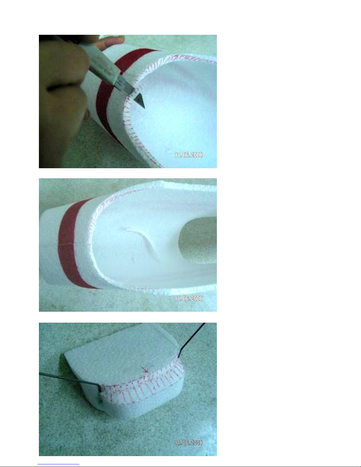
Step 15
Apply hot melt glue to the shaded
area.
Page 9
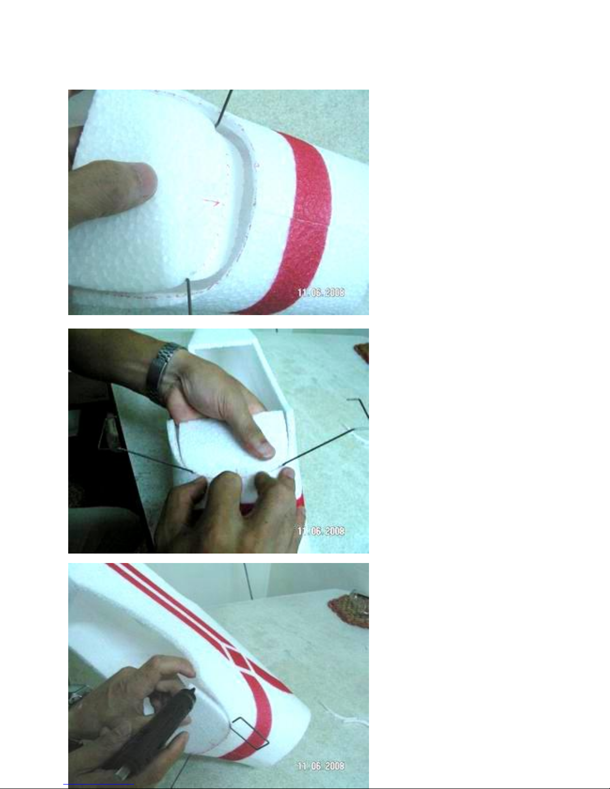
Step 16
Before the hot melt glue sets, place
the landing gear block into the fuse
and hold it until the glue sets.
Step 17
Apply hot melt glue to this area.
Hold them together until the glue
sets.
Page 10
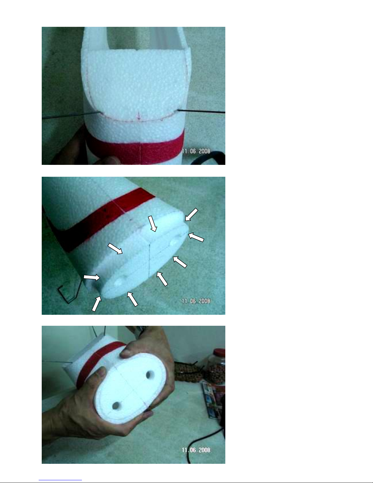
Step 18
Apply medium CA to the front foam
firewall as shown.
Step 19
Push the firewall in until it is flush
with the fuse sides. Spray the
assembly with accelerator and hold
until the glue sets. Spray the inside
of the fuse and firewall with
accelerator to set the glue.
Page 11
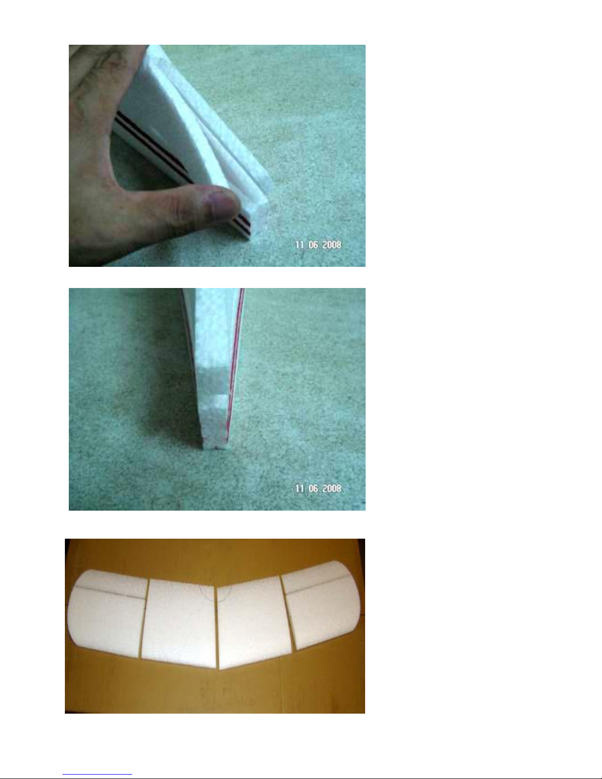
Step 20
Using CA glue the fuse sides
together where the vertical fin will
go.
Step 21
Use a hobby knife to trim the fuse
end square and cut a flat spot on the
top of the fuse to accept the vertical
fin.
Step 22
Get the 4 top wing sections and lay
them out. The top wing has the two
swept back center section and two
end sections. The two end sections
DO NOT have cut outs for the
aileron servos.
Page 12
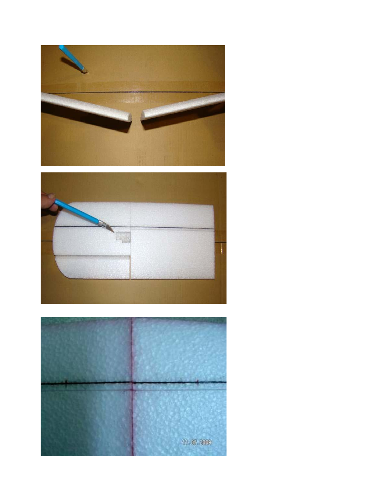
Step 23
The two lower wing center sections
have dihedral cut into them. DO NOT
confuse these with the two top pieces
without dihedral. The two lower wing
outer panels have cut outs in them for
servos.
Step 24
Glue the inner panels to the outer
panels using medium CA. Do this for
both the bottom and top wings. On
a flat surface insert a carbon flat
wing spar in each wing panel. Glue it
in with thin CA and accelerator.
Step 25
On a flat surface join the two top
wing halves together using medium
CA. There is no dihedral in the top
wing. Do the same for the bottom
wing
Page 13
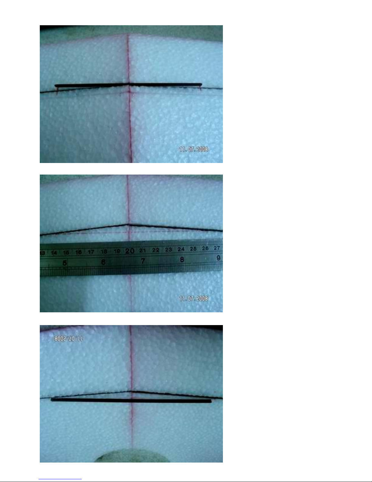
Step 26
Glue in the flat carbon wing center
reinforcement with thin CA and
accelerator on the bottom wing.
Step 27
On the top wing cut a slit in the foam
as shown to accept the top wing
center reinforcement.
Step 28
Glue it in place using thin CA and
accelerator.
Page 14
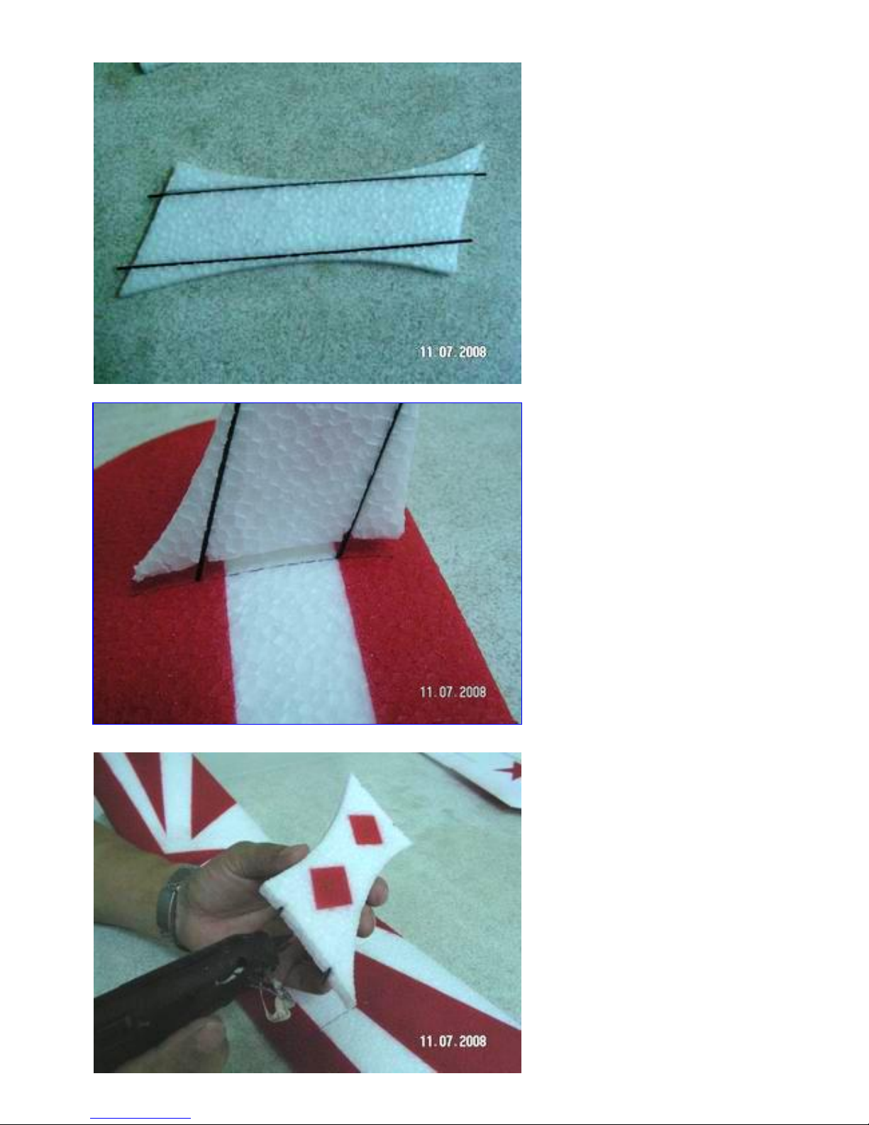
Step 29
Glue two pointed rods in each wing
strut with thin CA and accelerator.
Step 30
Dry fit the wing strut to the bottom
wing. Push the wires into the foam.
The position of the strut should be on
the line. The front edge of the strut
should be 23mm back from the front
edge of the bottom wing.
Step 31
Hot melt glue the struts to the bottom
of the wing.
Page 15
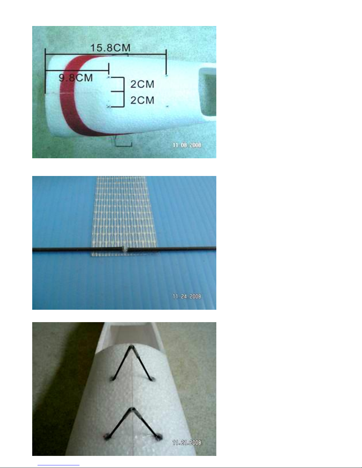
Step 32
Make holes in the top of the fuse for
the cabane struts as shown in the
photo.
Step 33
Make 4 carbon rods that are 5cm long.
Wrap them with clear duct tape.
Step 34
Insert the two cabane struts in the
holes of fuse previously made. Turn
the fuse over and put a few drops of
CA on the tape/ carbon strut
assembly.
Page 16
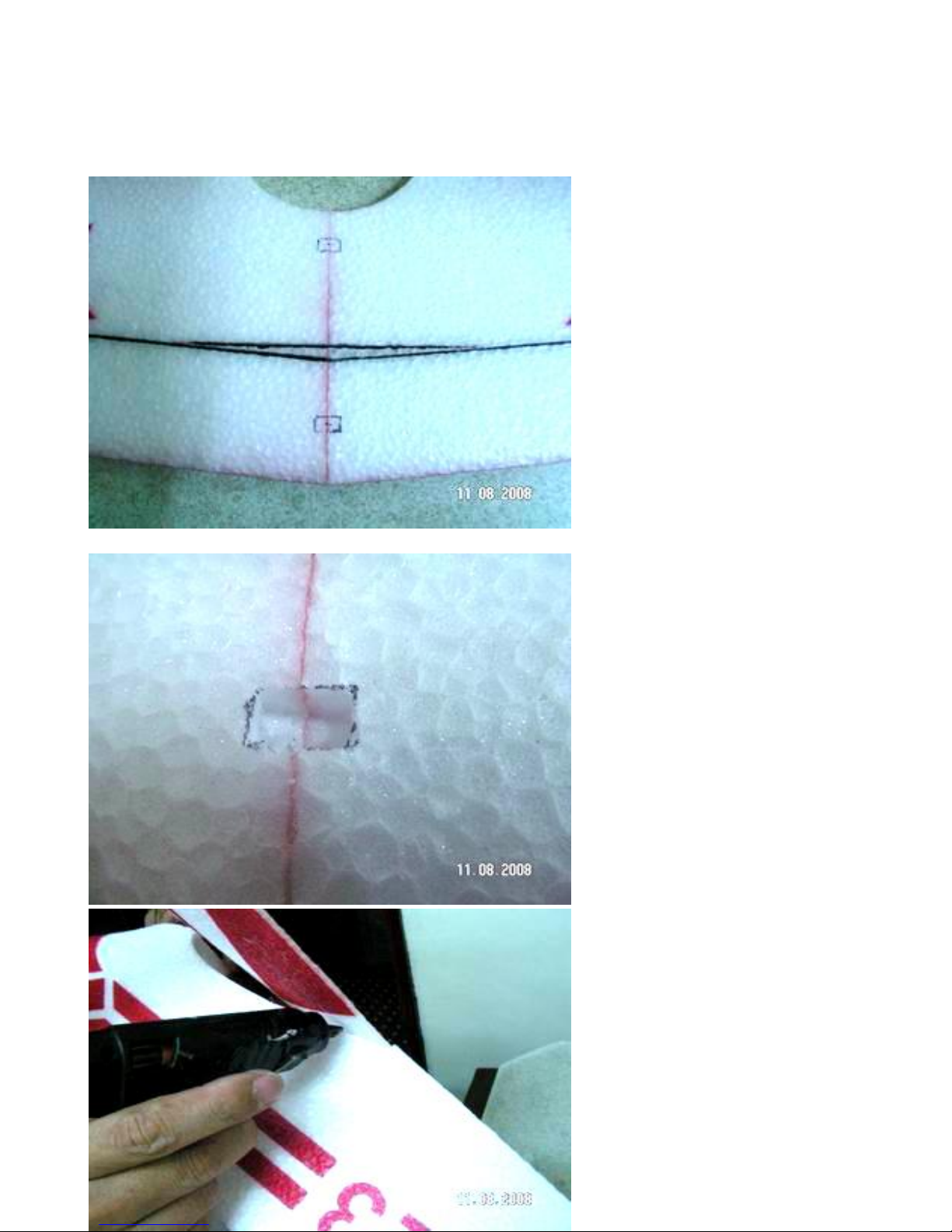
Step 35
On the bottom of the top wing make
two pockets 6cm square for the
cabane struts. The center for each
hole is 35mm and 95mm form the
front of the wing. Do not make a
hole through the wing.
Step 36
Glue the bottom wing to the fuse
with hot melt glue.
Page 17
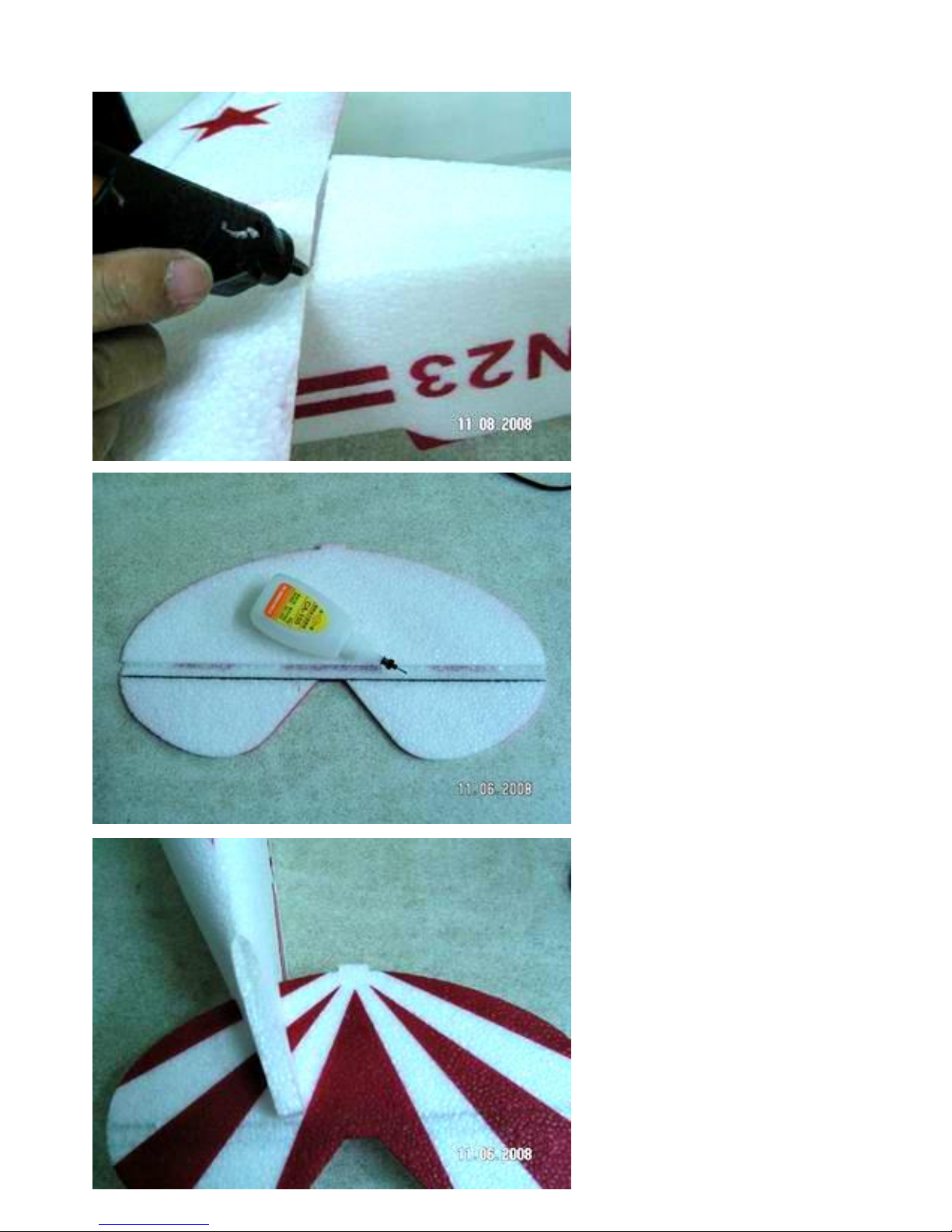
Glue the leading and trailing edge of
the bottom wing.
Step 37
Glue the carbon flat spar
reinforcement into the elevator with
thin CA and accelerator.
Step 38
Slide the elevator into the slot in the
fuse.
Page 18
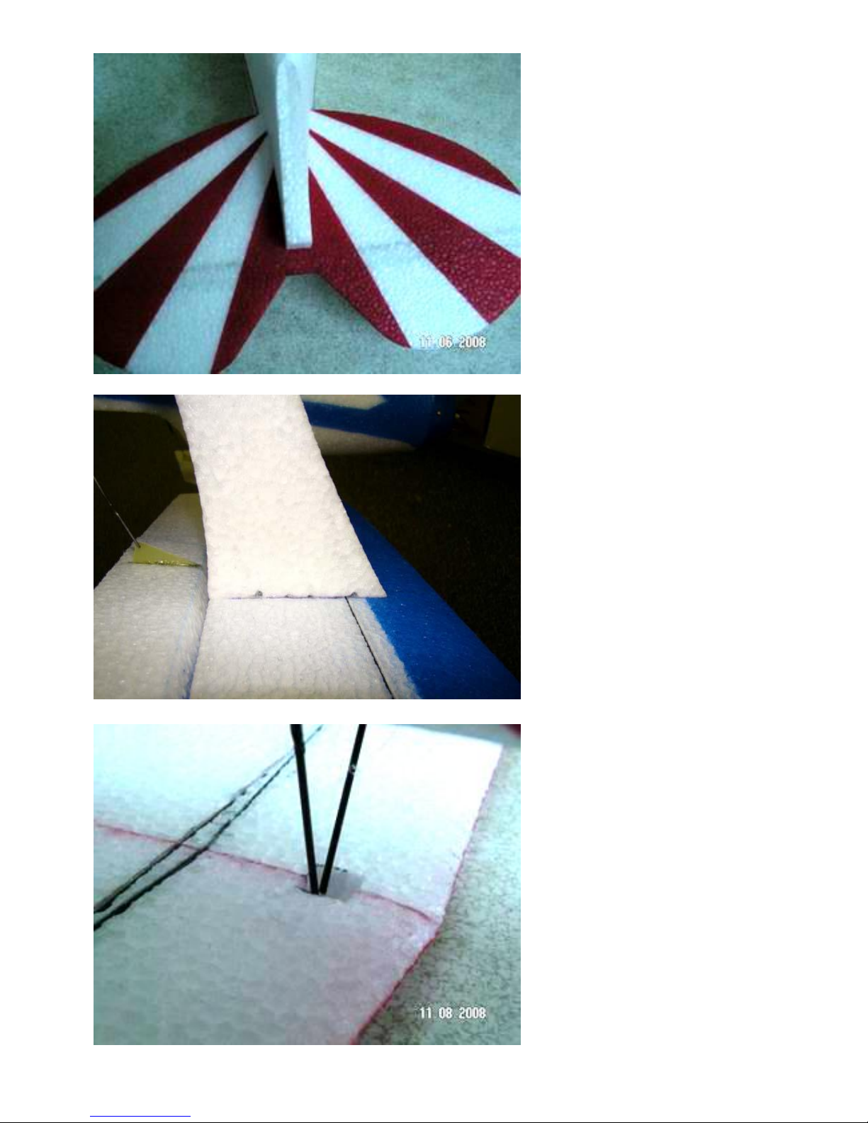
Step 39
Set the horizontal stab so that it is the
same distance side to side.
Step 40
Turn the plane over and insert the
wing strut into the top wing as shown.
Line the back of the strut up with the
leading edge of the aileron and the
two wires on the line that is marked
on the wing. When this is done hot
melt glue the struts to the top wing.
Step 41
Pull the two cabane struts into the
pockets in the top wing.
Page 19
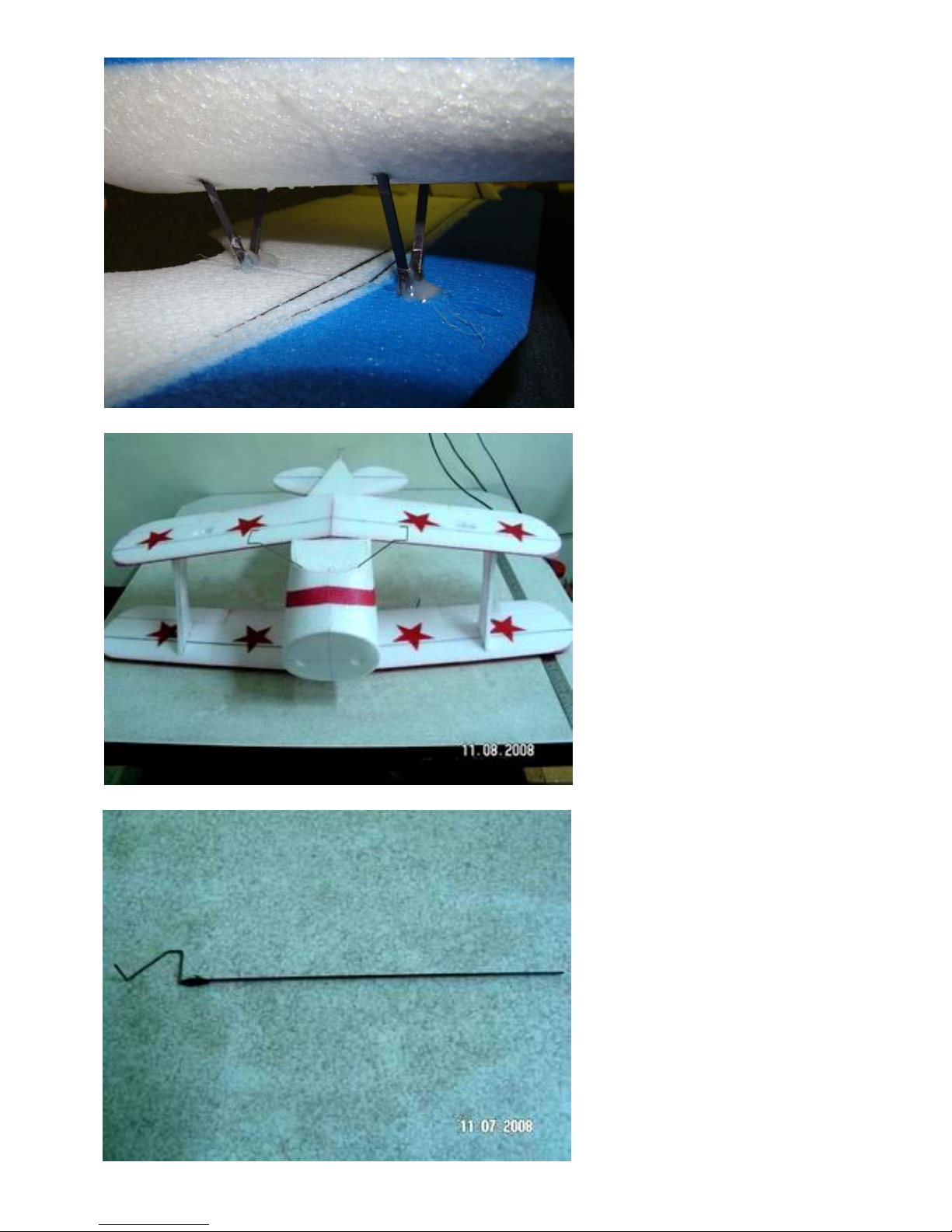
Step 42
Hot melt glue the two struts into the
top wing. Once the glue has set turn
the airplane over and pull the top
wing so that it is flat. When it is flat
glue the cabane struts to the fuse
using medium CA and accelerator.
Be careful not to put positive or
negative incidence in the top wing.
Step 43
Glue a carbon rod to the tail wheel
wire.
Page 20
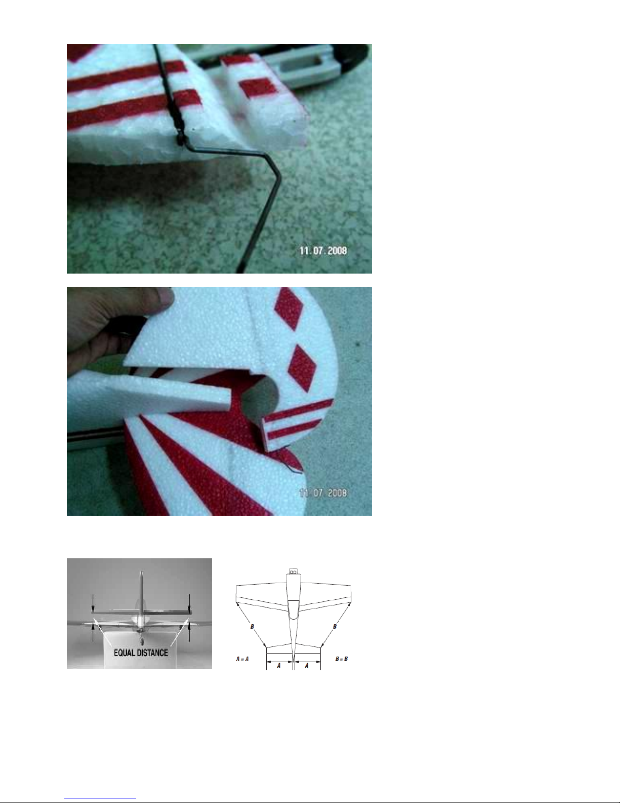
Step 44
Glue the assembly into the rudder
using thin CA and accelerator.。
Step 45
Glue the rudder and horizontal stab
to the airplane using medium CA and
accelerator. Make sure that the tail
surfaces are equal distance from the
main wing. See photos below.
Make sure that the tail surfaces are square and equal distance from the front wing.
Page 21
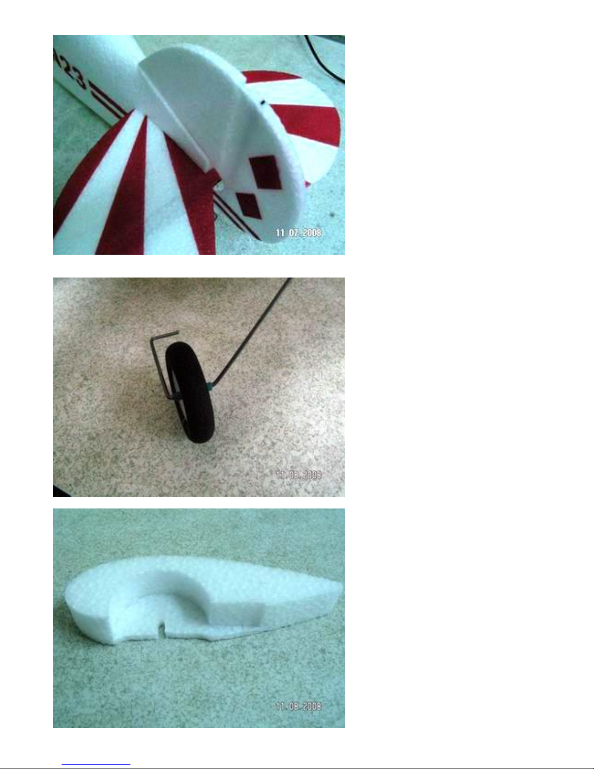
Step 46
Slip the wheels into place. Hold them in
place with heat shrink tubing. Put a
drop of thin CA on the tubing to hold it
in place.
Step 47
Build a left and right wheel pant from
the three pieces in the kit. Use medium
CA and accelerator to hold the pieces
together.
Page 22
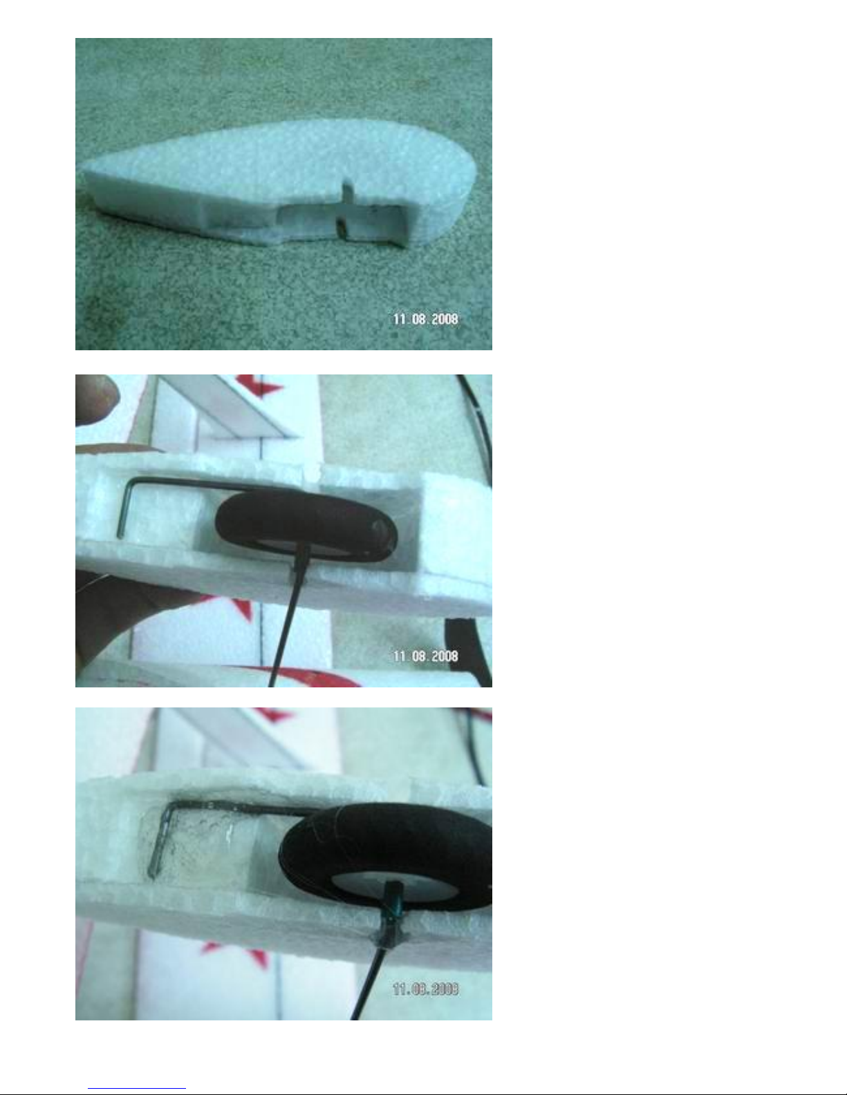
The completed wheel Pant
Step 48
Put the wheel pant over the wheel.
Use hot melt glue to hold the wheel
pant in place.
Page 23
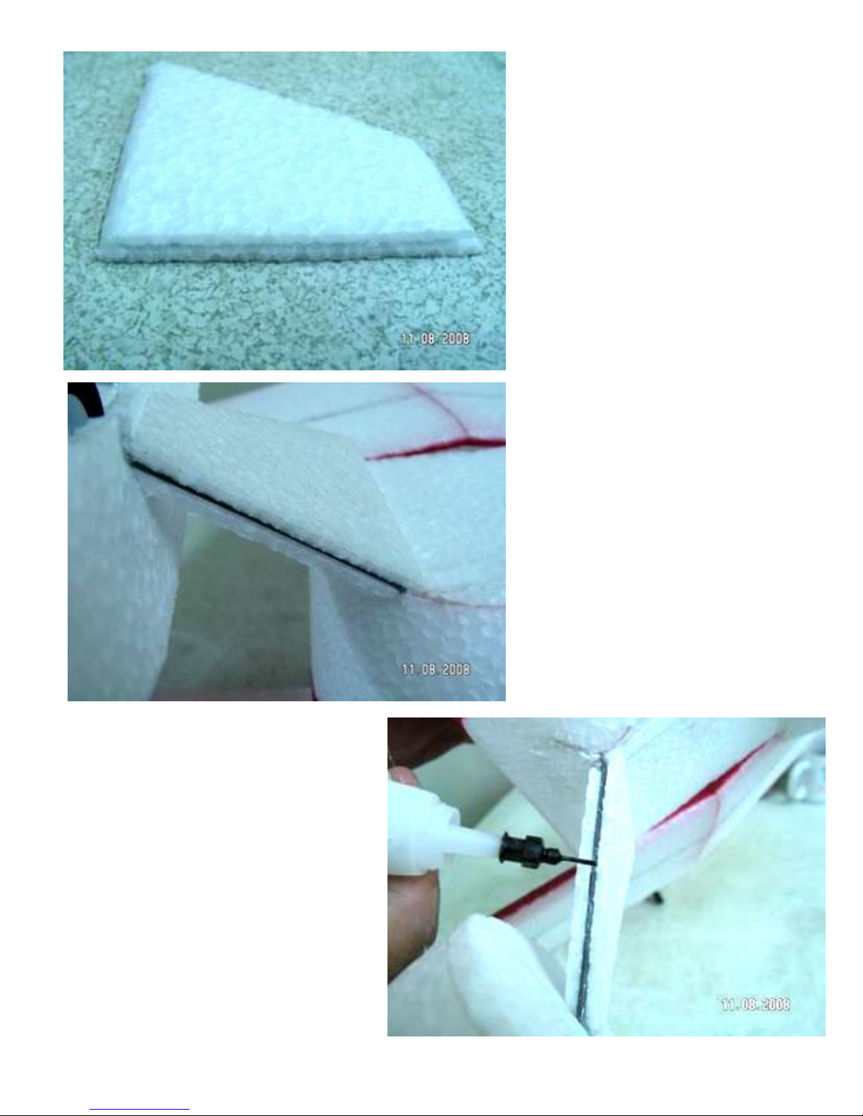
Step 49
From the parts grab the two triangle
shape landing gear reinforcements.
Position them on the landing gear wire
as shown.
Using medium CA glue the foam triangle
pieces in place. Use ht melt glue where the
piece mates to the fuse.
Page 24
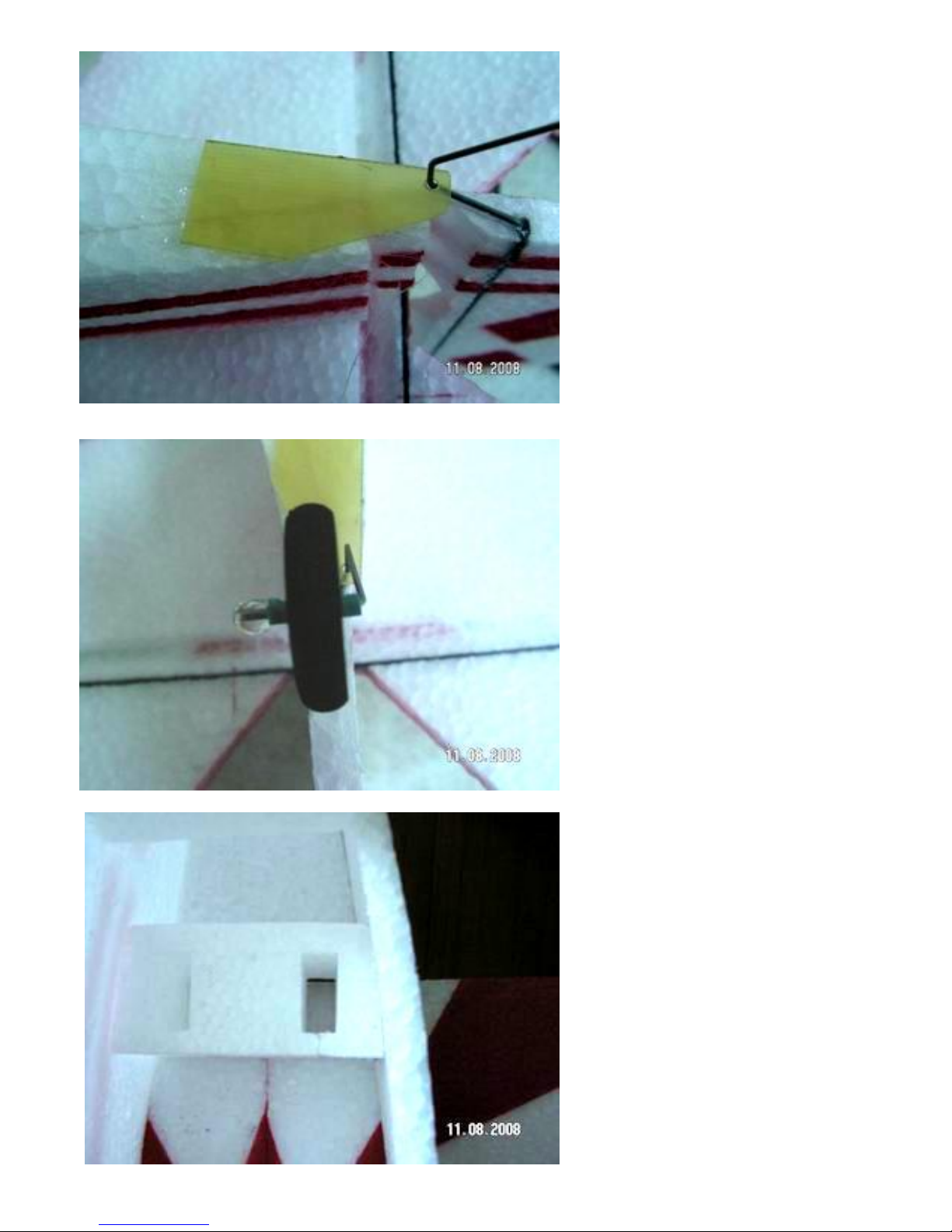
Step 50
Glue the tail wheel reinforcement on to
the plane with hot melt glue.
Secure the tail wheel with heat shrink
tubing and CA.
Step 51
Glue in the servo block as shown using
hot melt glue.
Page 25
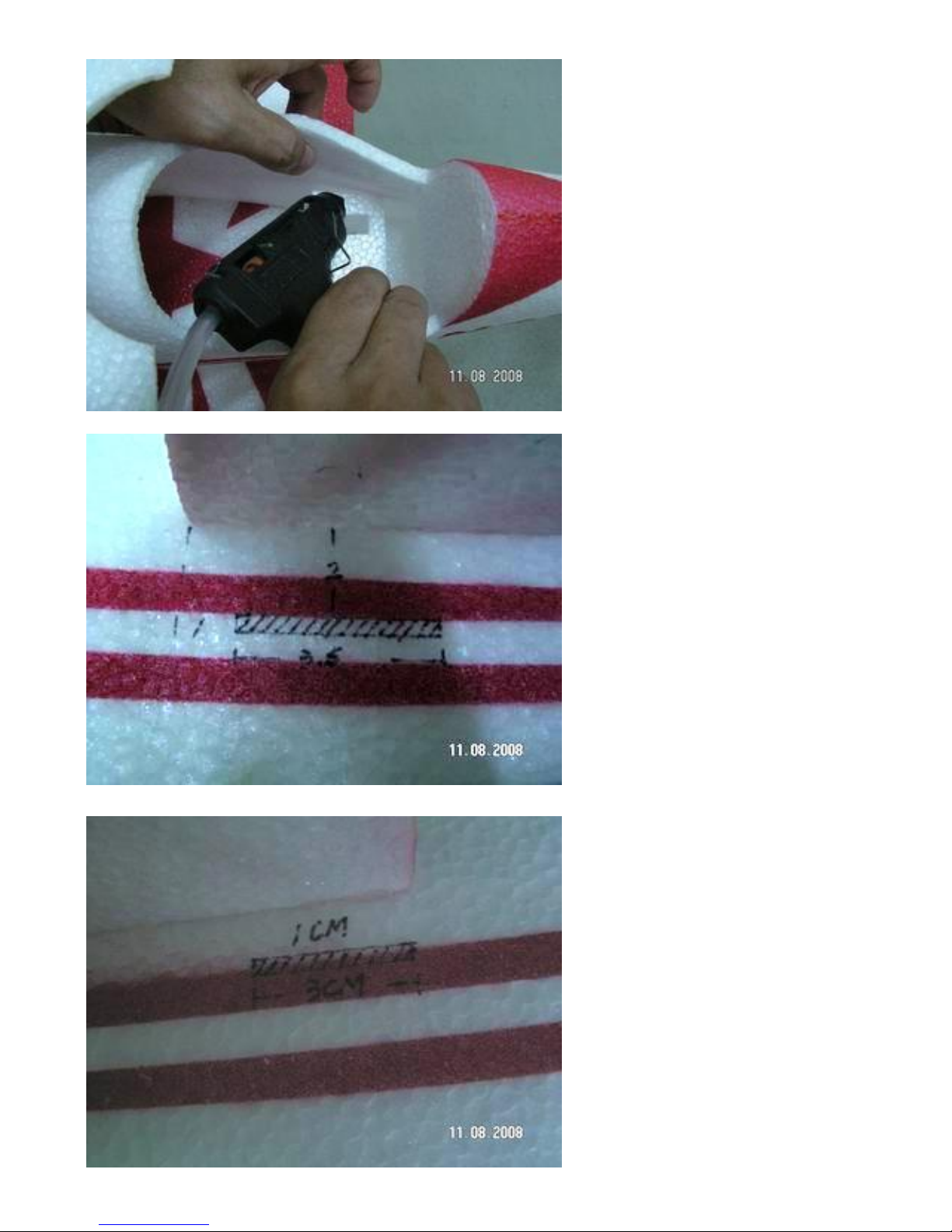
Step 52
Make a push rod cut out in the rear of
the fuse as shown for the rudder.
On the opposite side make a cut out as
shown for the elevator.
Page 26
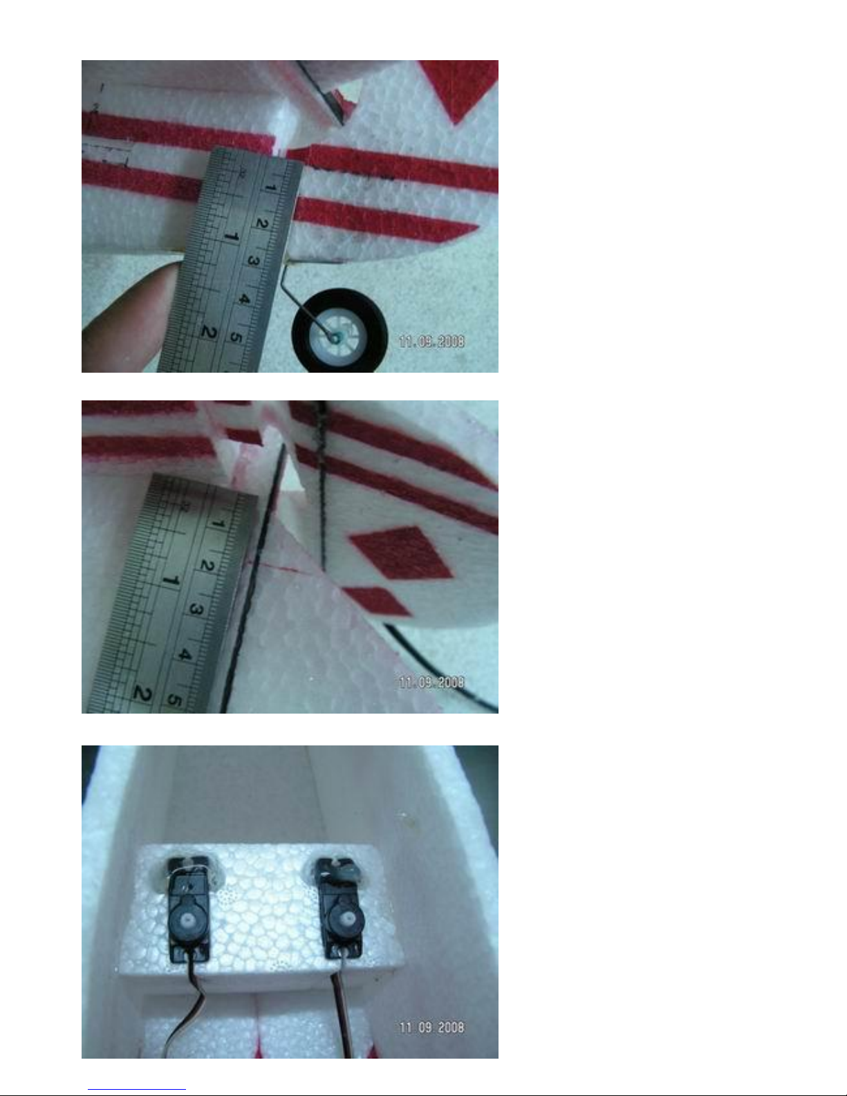
Step 53
Make a slit in the foam with a hobby
knife for the rudder control horn.
Make a slit in the elevator as shown
for the elevator control horn.
Step 55
Install the elevator and rudder servo
using hot melt glue.
Page 27
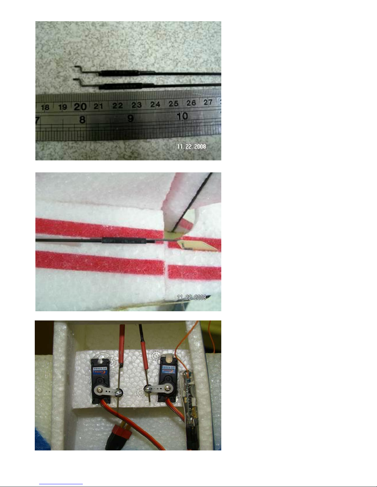
Step 56
Make up two carbon pushrods as
shown using the z bend and heat shrink
tubing. Wick a few drops of thin CA
into the joint and spray accelerator to
set the glue.
Step 57
Slip the rudder control horn over the z
bend wire. Put the control rod through
the fuse as shown.
Step 58
Hook up the control rods as shown.
Now with thin CA glue in the control
horn for the rudder. Follow the same
procedure for the elevator.
Page 28
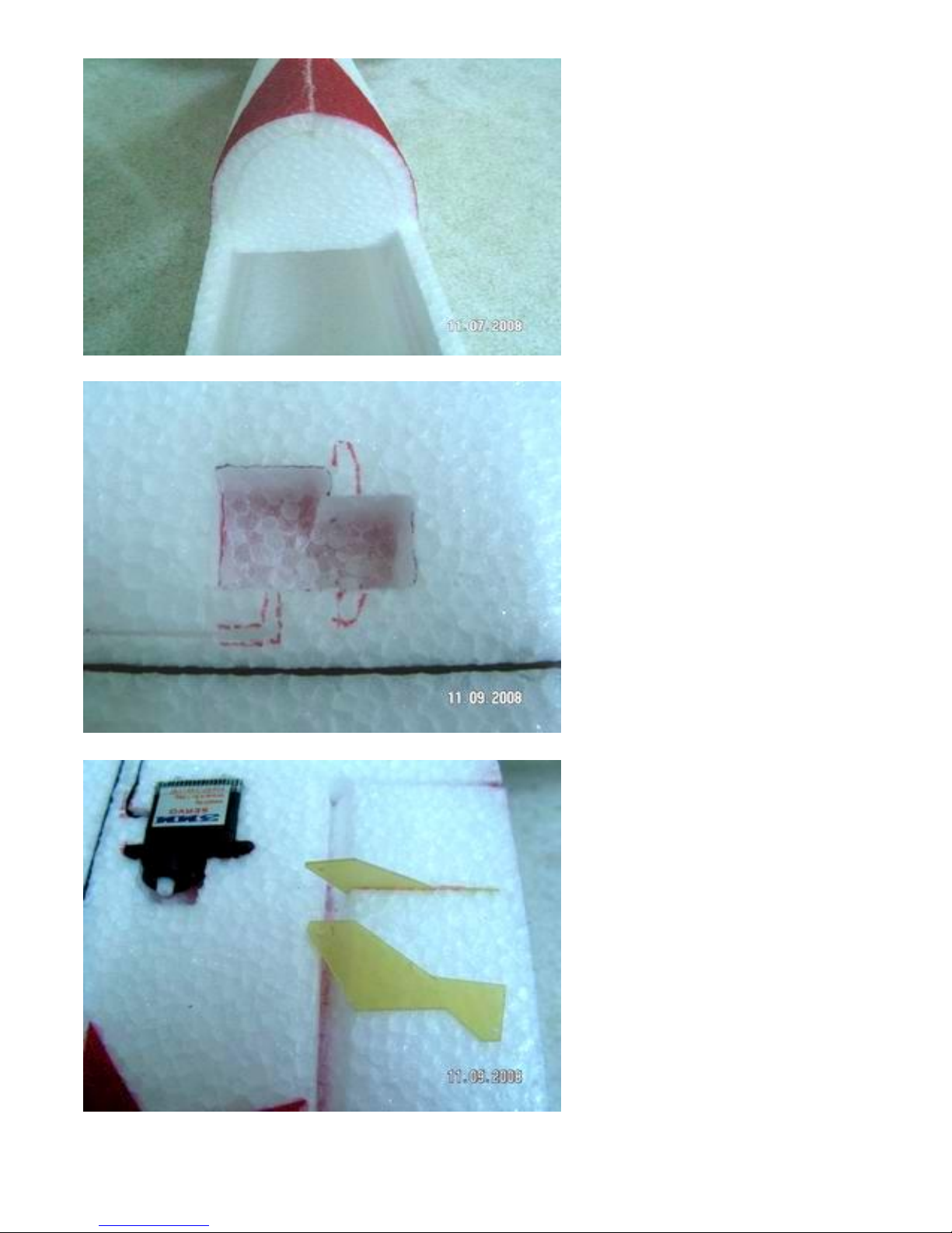
Step 59
Glue in the rear turtle deck cockpit
using medium CA.
Step 60
On the bottom wing custom fit the
servo holes to fit your servos.
Step 61
Install the two aileron servos with hot
melt glue. Make a slit in each aileron
for the control horn. Install the control
horn as shown. Glue it in with thin
CA.
Page 29
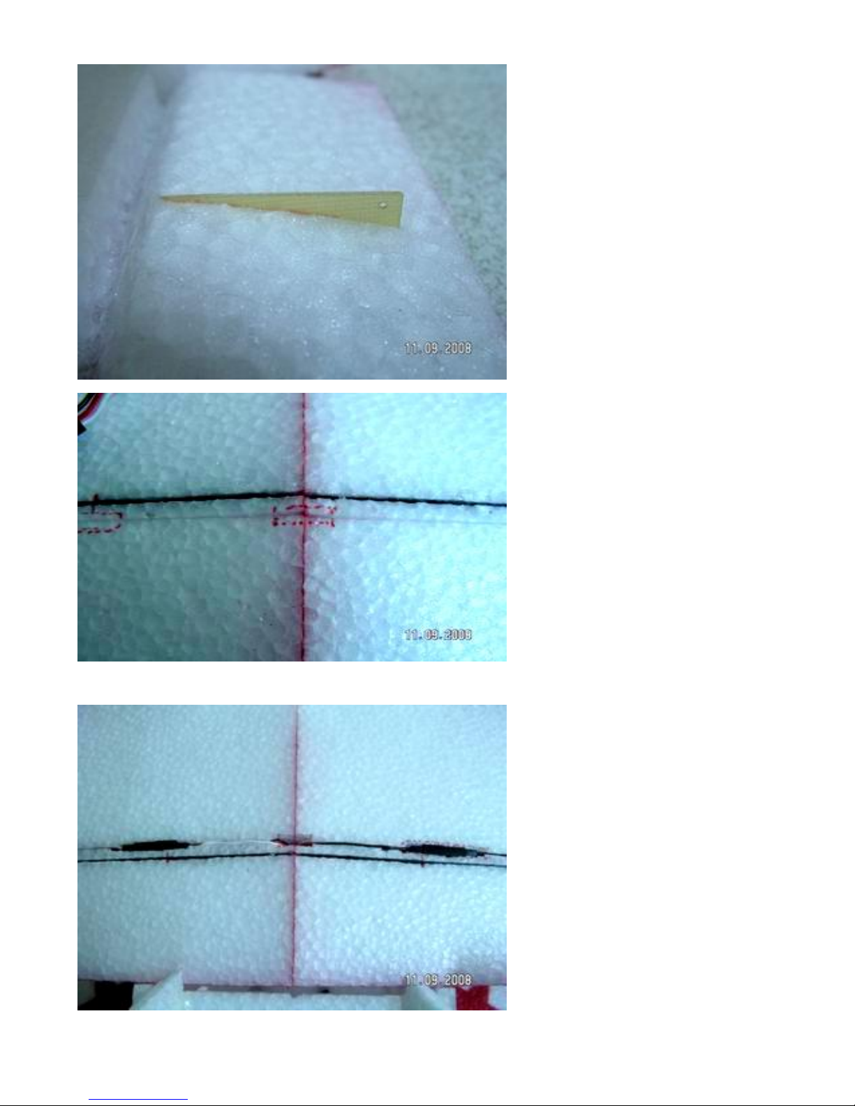
Step 62
On the top wing make a slit in each
aileron for the control horn. Glue it in
with thin CA.
Step 63
On the center of the bottom wing
make a hole for the servo leads to go
through.
Push the servo wires into the slot on
the bottom wing.
Page 30
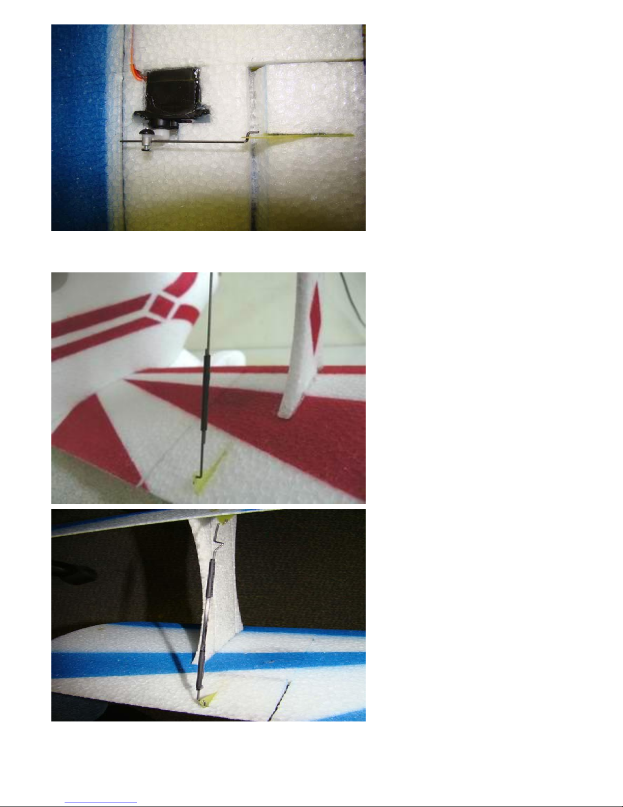
Step 64
Hook up the ailerons as shown.
Step 65
Assemble the push rods between the
ailerons as shown using carbon rods, Z
bends and heat shrink tubing.
Put a bend in the wire as shown. This
will allow you to make adjustments
between the top and bottom ailerons.
Page 31
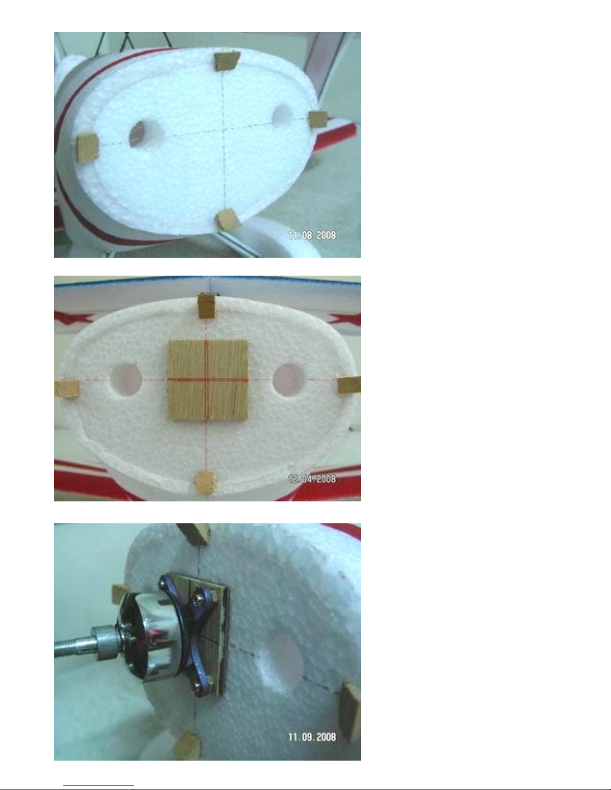
Step 66
Using hot melt glue attach the cowl
mounting blocks to the front firewall.
Step 67
Glue the wood motor mount to the
front of the airplane as shown.
Step 68
Mount the motor to the airplane with
four wood screws. Put a couple of
washers behind the motor to give it
some right thrust. Hook up the wires
for the speed controller.
Page 32
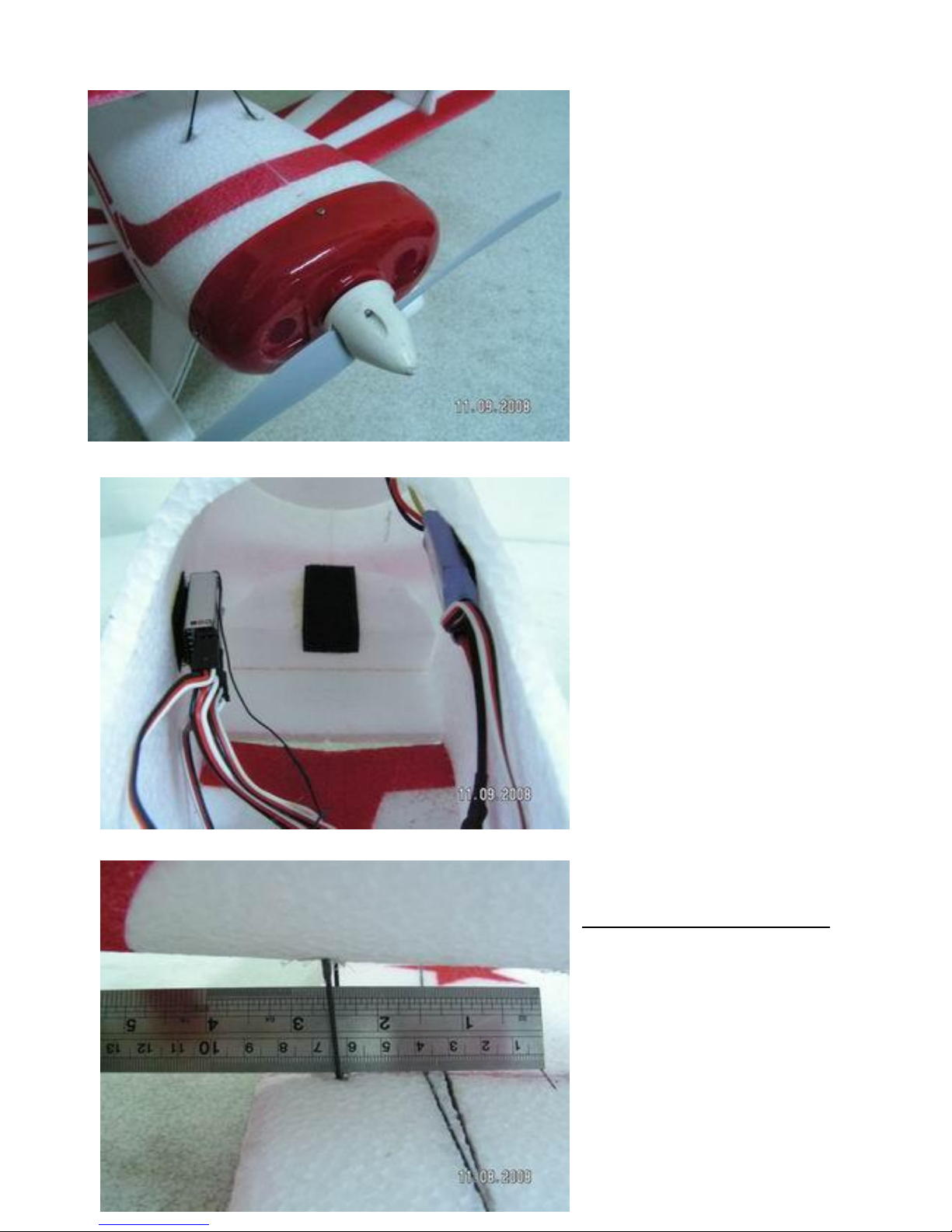
Step 69
Attach the cowl, prop and spinner.
Step 70
Install the receiver and make all of
the servo connections.
Step 71
The Center of gravity is 3.5 inches
back from the leading edge of the top
wing.
Page 33
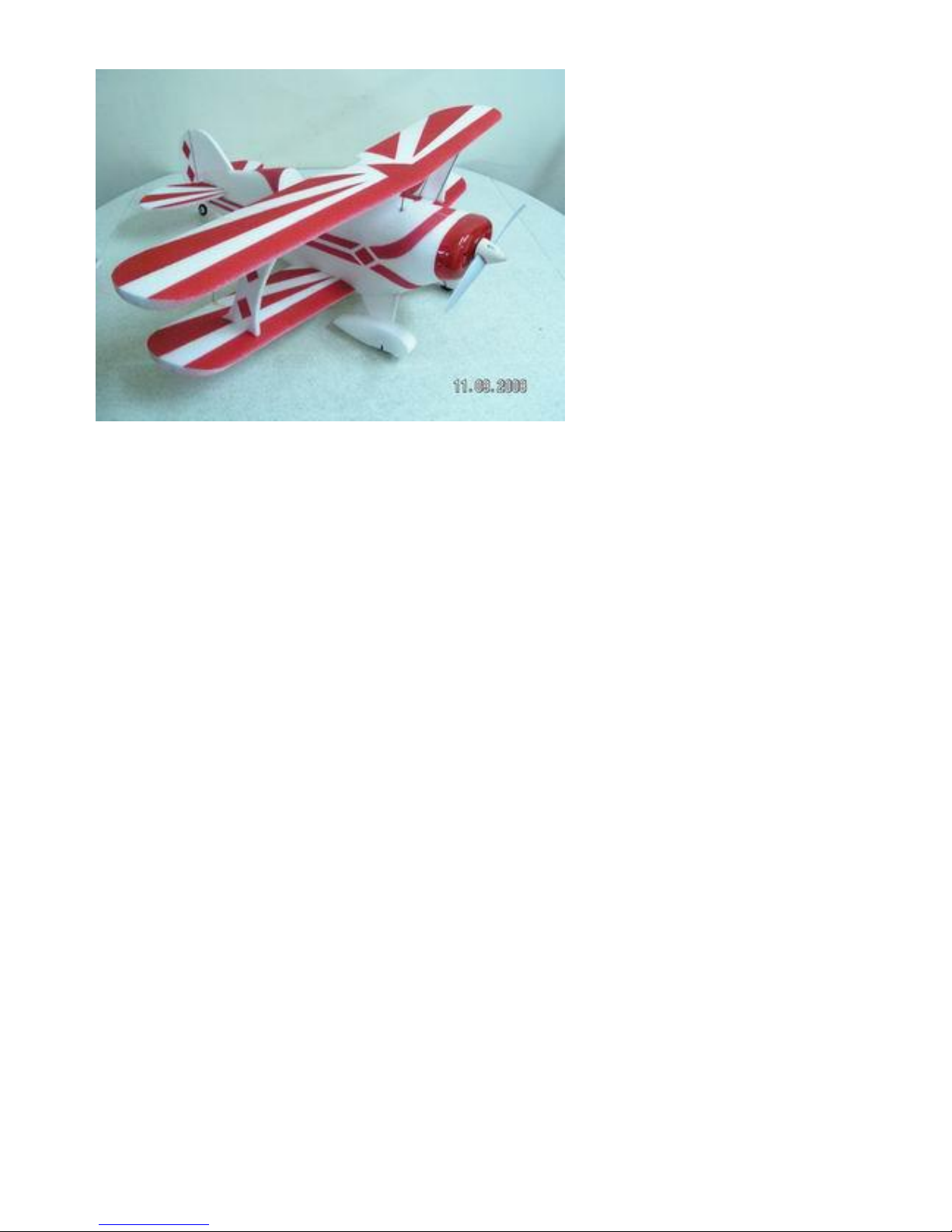
Step 72
Your Pitts should be ready to fly. For
the initial flight set the control throws
to the following. You can always add
more throw after you get comfortable
with the plane.
Ailerons- 5/8 inch up and down
Elevator- ½ inch up and down.
Rudder- 1 ½ inch left and right
 Loading...