

Page 1

USER’S
MANUAL
BPC-8590
All-in-One Book-size PC
Intel® Core 2 Duo
For Socket 478 System
BPC-8590 M1
Page 2

Copyright Notice
BPC-8590 All-in-One
Book-size PC
OPERATION MANUAL
COPYRIGHT NOTICE
This operation manual is meant to assist users in installing and setting up the
system. The information contained in this document is subject to change
without prior any notice.
This manual is copyrighted January, 2008. You may not reproduce or
transmit in any form or by any means, electronic, or mechanical, including
photocopying and recording.
ACKNOWLEDGEMENTS
All trademarks and registered trademarks mentioned herein are the property
of their respective owners.
CE NOTICE
This is a class B product. In a domestic environment this product may cause
radio interference in which case the user may be required to take adequate
measures.
Page 3

Copyright Notice
FCC NOTICE
This equipment has been tested and found to comply with the limits for a
Class A digital device, pursuant to part 15 of the FCC Rules. These limits are
designed to provide reasonable protection against harmful interference when
the equipment is operated in a commercial environment. This equipment
generates, uses, and can radiate radio frequency energy and, if not installed
and used in accordance with the instruction manual, may cause harmful
interference to radio communications. Operation of this equipment in a
residential area is likely to cause harmful interference in which case the user
will be required to correct the interference at his own expense.
You are cautioned that any change or modifications to the equipment not
expressly approve by the party responsible for compliance could void your
authority to operate such equipment.
CAUTION
Danger of explosion if battery is incorrectly replaced.
Replace only with the same or equivalent type recommended by the manufacturer.
Dispose of used batteries according to the manufacturer’s instructions.
Installation only by a trained electrician or only by an electrically trained person who knows
all English Installation and Device Specifications which are to be applied.
Page 4

Contents
TABLE OF CONTENTS
CHAPTER 1 INTRODUCTION
1-1 About This Manual .................................................... 1-2
1-2 Case Illustration .......................................................... 1-3
1-3 System Specification ................................................... 1-4
1-4 Safety Precautions ...................................................... 1-5
CHAPTER 2 SYSTEM CONFIGURATION
2-1 Jumper & Connector Quick Reference Table .............. 2-2
2-2 Component Locations ................................................... 2-3
2-3 How to Set the Jumpers ................................................ 2-4
2-4 FSB Frequency Selection …………………………………….
2-6
2-5 COM1 Port RI & Voltage Selection …………………………
2-7
2-6 COM2 Port RI & Voltage Selection .....................……………
2-8
2-7 COM3 Port RI/Voltage Selection ………………..…….……
2-9
2-8 COM4 Port RI/Voltage Selection ………………..…….……
2-10
2-9 Keyboard/ Mouse Selection ..………………..…….…………
2-11
2-10 Clear CMOS Data Selection ….……………..…….………….
2-12
2-11 Reset/ NMI/ Clear Watchdog Selection ………………………
2-13
2-12 COM Port Connector ….......……...………………………….
2-14
2-13 Keyboard/ Mouse Connector …………………………………
2-16
2-14 Power Button .........................….......................……………..
2-16
2-15 CPU Fan Connector ... ………………………………………..
2-16
2-16 System Fan Connector ………….……………………………
2-17
2-17 VGA Connector …….……………………………………….
2-17
2-18 DVI Connector …………….…………………………………
2-18
2-19 Hard Disk Drive Connector ………………………………….
2-19
2-20 Serial ATA Connector …………………….…………………
2-20
2-21 Printer Connector …...............................……..........................
2-21
2-22 Universal Serial Bus Connector ………………………………
2-22
2-23 LAN Connector ……………………………………………..
2-23
2-24 LAN LED Connector ………………………………..………
2-24
2-25 ATX Power Connector ……..........………....………..……..
2-24
2-26 Line-Out Connector …….....................……….………......….
2-25
2-27 Line-In Connector ……………………...................………….
2-25
2-28 MIC Connector .…………………………………..…............
2-25
2-29 Memory Installation …………………………………………..
2-25
2-30 PCI Connector ……………………..…………………………
2-26
Page 5

Contents
CHAPTER 3 SOFTWARE UTILITIES
3-1 Introduction ................................................................ 3-2
3-2 VGA Driver Utility ..................................................... 3-3
3-3 Flash BIOS Update ..................................................... 3-4
3-4 LAN Driver Utility ..................................................... 3-6
3-5 Sound Driver Utility ................................................... 3-7
3-6 Intel Chipset Software Installation Utility …..……... 3-8
3-7 Watchdog Timer Configuration ……………………. 3-9
CHAPTER 4 AWARD BIOS SETUP
4-1 Introduction ................................................................ 4-2
4-2 Entering Setup ........................................................... 4-3
4-3 The Standard CMOS Features ……............................ 4-4
4-4 The Advanced BIOS Features ..........................…....... 4-7
4-5 Advanced Chipset Features ......................................... 4-10
4-6 Integrated Peripherals ................................................. 4-12
4-7 Power Management Setup .......................................... 4-17
4-8 PNP/PCI Configuration .............................................. 4-18
4-9 PC Health Status …………………………………… 4-20
4-10 Load Fail-Safe Defaults .............................................. 4-21
4-11 Load Optimized Defaults ............................................ 4-21
4-12 Password Settings ....................................................... 4-22
4-13 Save & Exit Setup ...................................................... 4-23
4-14 Exit Without Saving ................................................... 4-24
APPENDIX A SYSTEM ASSEMBLY
Exploded Diagram for Whole System Unit ............................ A-2
APPENDIX B TECHNICAL SUMMARY
Block Diagram ...................................................................... B-2
Interrupt Map ........................................................................ B-3
RTC & CMOS RAM Map ..................................................... B-4
Timer & DMA Channels Map ............................................... B-5
I/O & Memory Map .............................................................. B-6
Page 6

Page:1-1
INTRODUCTION
This chapter gives you the information for BPC-8590. It also
outlines the System specification.
Section includes:
z About This Manual
z System Specifications
z Safety precautions
Experienced users can skip to chapter 2 on page 2-1
for Quick Start.
CHAPTER
1
Page 7

Chapter 1 Introduction
Page: 1-2
BPC-8590 USER
′
S MANUAL
1-1. ABOUT THIS MANUAL
Thank you for purchasing our BPC-8590 Core 2 Duo Book-size PC enhanced
with VGA / Sound / LAN, which is fully PC / AT compatible. BPC-8590
provides faster processing speed, greater expan dability and can handle more
task than before. This manual is designed to assist you how to install and set
up the system. It contains four chapters. The user can apply this manual for
configuration according to the following chapters :
Chapter 1 Introduction
This chapter introduces you to the background of this manual, illustration of
the case, and the specifications for this system. The final page of this chapter
indicates some safety reminders on how to take care of your system.
Chapter 2 Hardware Configuration
This chapter outlines the component location and their functions. In the end of
this chapter, you will learn how to set jumper and how to config ure this card
to meet your own needs.
Chapter 3 Software Utilities
This chapter contains helpful information for proper installations of the VGA
utility, LAN utility, sound utility, and BIOS update. It also describes the
Watchdog timer configuration.
Chapter 4 Award BIOS Setup
This chapter indicates you how to set up the BIOS configurations.
Appendix A System Assembly
This appendix contain exploded diagram of the system
Appendix B Technical Summary
This section gives you the information about the Technical maps.
Page 8
Chapter 1 Introduction
BPC-8590 USER′S MANUAL
Page: 1-3
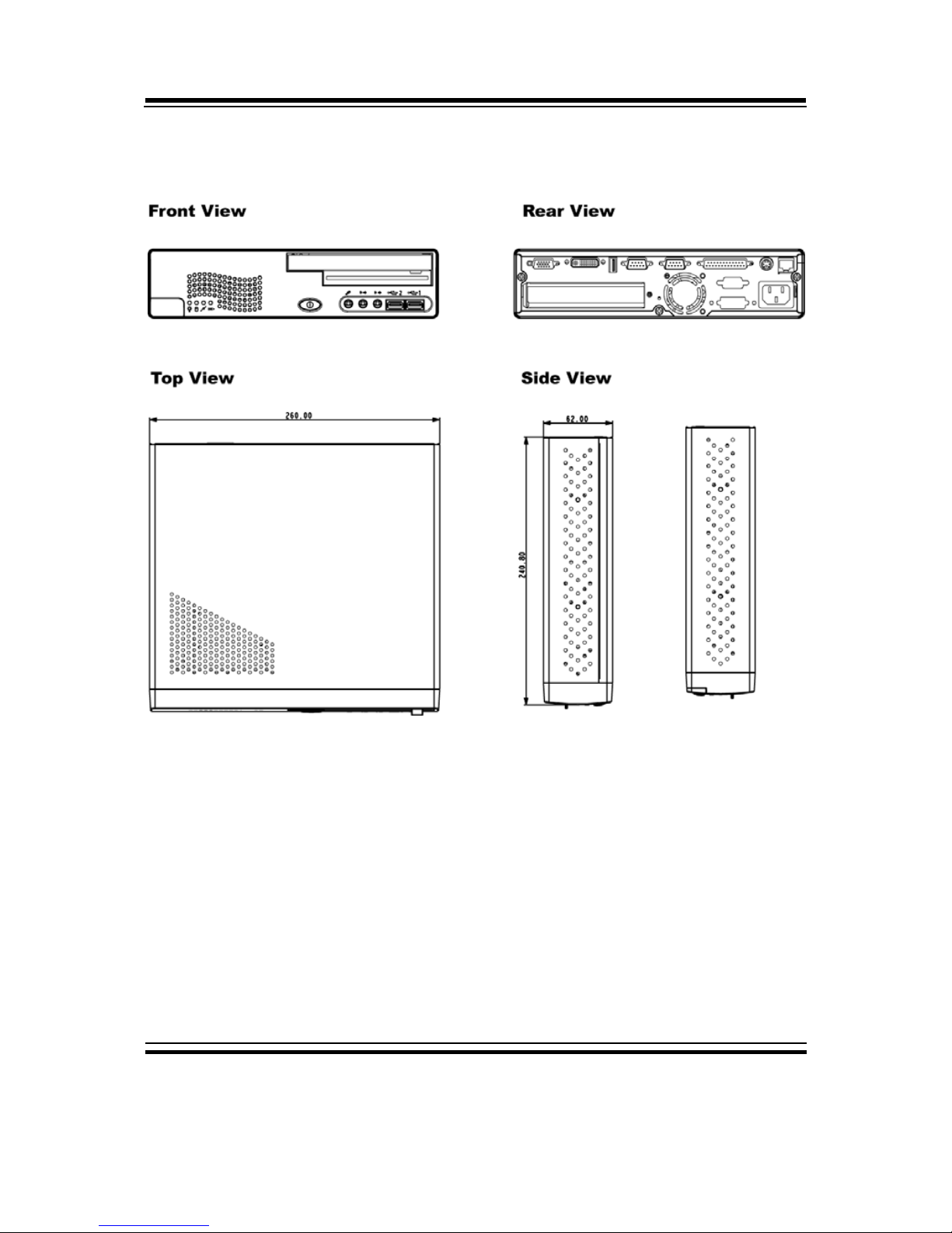
1-2. CASE ILLUSTRATION
Page 9

Chapter 1 Introduction
Page: 1-4
BPC-8590 USER
′
S MANUAL
1-3. SYSTEM SPECIFICATION
z PROCESSOR
Core 2 Duo / Core Duo / Celeron-M Socket 478 on board for 65nm CPU (up to
2.16GHz).
z CHIPSET
Intel 945GM + ICH7R (FSB: 533/667MHz)
z MEMORY
2 x 240 pin DDR2 DIMM, Support DDR2 667 (up to 2GB)
z DRIVER BAY
1 x 2.5” SATA HDD
z
POWER SUPPLY
AC 100~240V input, ATX 110W output
z
I/O PORT
Front Bezel
2x USB 2.0 (Type A)
3x Audio port (Line-in, Line-out, MIC)
1x Slim CD / DVD ROM (Optional)
1x Slim Floppy (Optional)
1x Power Switch
4x LED indicators (Power, HDD, LAN-on and LAN-working)
Rear Panel
1 x VGA Connecter (D-sub 15 pin)
1 x DVI-I Connecter
1 x USB 2.0 (Type A)
4 x COM Port RS-232 (D-sub 9 Pin) contain 5V/12V power capability
1 x Parallel Port (D-sub 25 pin)
1 x RJ45 Giga LAN
1 x PS/2 (Mini-Din 6 Pin) for K/B and Mouse with Y cable
Expansion Slot : 1 x PCI or ,1x PCI-E (Optional)
Page 10

Chapter 1 Introduction
BPC-8590 USER′S MANUAL
Page: 1-5
z
CHASSIS DIMENSION
260 x 240 x 62 (mm) / 10.24 x 9.45 x 2.44 (in)
z WEIGHT
3.3Kg
z ENVIRONMENT TEST
Operating temperature 0°~40°C
Operating humidity 10~90%.
z CERTIFICATION
CE ,FCC, CLASS-B
1-4. SAFETY PRECAUTIONS
Following messages are safety reminders on how to protect your systems from
damages. And thus, helps you lengthen the life cycle of the system.
1. Check the Line Voltage
a. The operating voltage for the power supply should cover the range of
100VAC-240VAC, otherwise the system may be damaged.
2. Environmental Conditions
a. Place your BPC-8590 on a sturdy, level surface. Be sure to allow
enough room on each side to have easy access.
b. Avoid extremely hot or cold places to install your BPC-8590 Book-sized
PC.
c. Avoid exposure to sunlight for a long period of time (for example in a
closed car in summer time. Also avoid the system from any heating
device.). Or do not use BPC-8590 when it‘s been left outdoors in a cold
winter day.
d. Bear in mind that the operating ambient temperature is from 0°C up to
+40°C (32°F~104°F).
e. Avoid moving the system rapidly from a hot place to a cold place or vice
versa because condensation may come from inside of the system.
f. Place BPC-8590 against strong vibrations, which may cause hard disk
failure.
g. Do not place the system too close to any radio active device. Radio-
Page 11

Chapter 1 Introduction
Page: 1-6
BPC-8590 USER
′
S MANUAL
active device may cause interference.
3. Handling
a. Avoid putting heavy objects on top of the system.
b. Do not turn the system upside down. This may cause the floppy drive
and hard drive to mal-function.
c. Do not remove the diskette from the Floppy drive while the light is still
on. If you remove the diskette while the light is on, you may damage
the information on the diskette.
d. Do not allow foreign objects to fall into this product.
e. If water or other liquid spills into this product, unplug the power cord
immediately.
4. Good Care
a. When the outside of the case is stained, remove the stain with neutral
washing agent with a dry cloth.
b. Never use strong agents such as benzene and thinner to clean the system.
c. If heavy stains are present, moisten a cloth with diluted neutral washing
agent or with alcohol and then wipe thoroughly with a dry cloth.
d. If dust has been accumulated on the outside, remove it by using a special
made vacuum cleaner for computers.
Page 12

Page 2-1
HARDWARE
CONFIGURATION
** QUICK START **
CHAPTER
2
Helpful information describes the jumper & connector settings, and
component locations.
Section includes:
z Jumper & Connector Quick Reference Table
z Component Locations
z Configuration and Jumper settings
z Connector’s Pin Assignments
Page 13

Chapter 2 Hardware Configuration
Page: 2-2
BPC-8590 USER
′
S MANUAL
2-1. JUMPER & CONNECTOR QUICK REFERENCE TABLE
FSB Frequency Selection ………………………………
JP11
COM1 Port RI/Voltage Selection ………………….…
JP2
COM2 Port RI/Voltage Selection ………………….…
JP1
COM3 Port RI/Voltage Selection ………………….…
JP4
COM4 Port RI/Voltage Selection ………………….…
JP5
Keyboard/ Mouse Selection ……………………………
JP22
Clear CMOS Data Selection ……………………………
JP15
Reset/ NMI/ Clear Watchdog Selection ………………..
JP17
COM Port Connector ....................…..................………
…………………………………..
COM1, COM2
COM3, COM4
Keyboard/ Mouse Connector ….......……..……………
KB1
Power Button …………………………………….
JPWBT1
CPU Fan Connector ……………………………………
JCFAN1
System Fan Connector …………………………………
JSFAN2
VGA Connector ………………………………………..
VGA1
DVI Connector …………………………………………
DVI1
Hard Disk Drive Connector …..............…….........…….
IDE1-1
Serial ATA Connector ………………………………….
SATA1, SATA2
Printer Connector …….....................……………......…
JPRT1
Universal Serial Bus Connector …….....................…..
JUSB1, JUSB2, USB1, USB2,
USB3
LAN Connector ……………………………………….
LAN1, JLAN2 (option)
ATX Power Connector …………………………………
JATX_PWR1
Line-Out Connector …………………………………….
LINE_OUT
Line-In Connector ……………………………………...
LINE_IN
MIC Connector ………………………………………..
MIC
Memory Installation ..................................…......………
JDIMM1, JDIMM2
PCI Connector ……………………….…………
PCI1
Page 14
Chapter 2 Hardware Configuration
BPC-8590 USER′S MANUAL
Page: 2-3
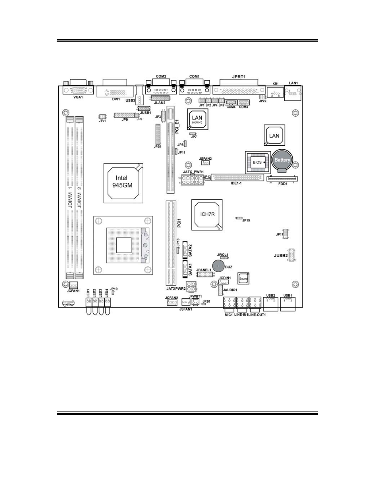
2-2. COMPONENT LOCATIONS
BPC-8590 Connector, Jumper and Component locations
Page 15
Chapter 2 Hardware Configuration
Page: 2-4
BPC-8590 USER
′
S MANUAL
2-3. HOW TO SET THE JUMPERS
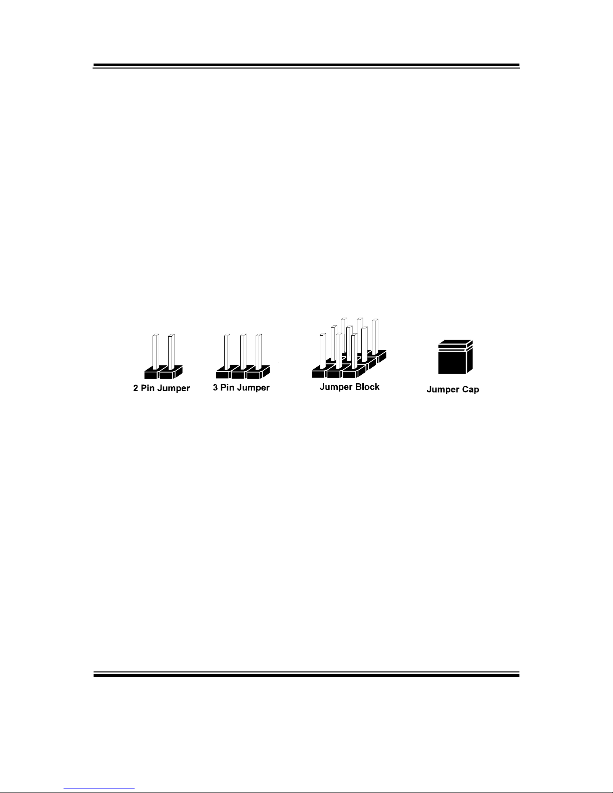
You can configure your board by setting jumpers. Jumper is consists of
two or three metal pins with a plastic base mounted on the card, and by
using a small plastic "cap", Also known as the jumper cap (with a metal
contact inside), you are able to connect the pins. So you can set-up your
hardware configuration by "open" or "close" pins.
The jumper can be combined into sets that called jumper blocks. When
the jumpers are all in the block, you have to put them together to set up
the hardware configuration. The figure below shows how this looks like.
JUMPERS AND CAPS
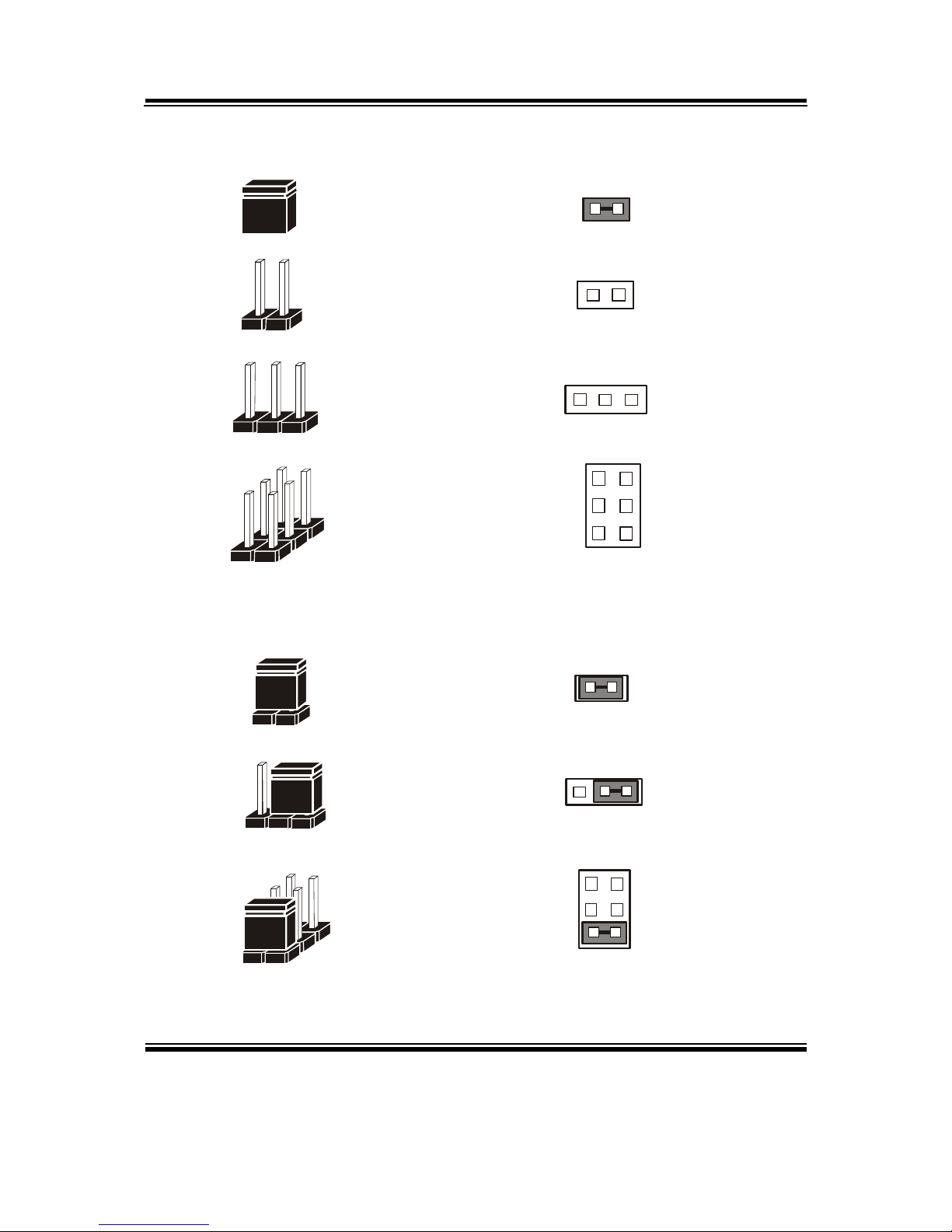
If a jumper has three pins (for examples, labelled PIN1, PIN2, and PIN3),
You can connect PIN1 & PIN2 to create one setting and shorting. You
can either connect PIN2 & PIN3 to create another setting. The same
jumper diagrams are applied all through this manual. The figure below
shows what the manual diagrams look and what they represent.
Page 16
Chapter 2 Hardware Configuration
BPC-8590 USER′S MANUAL
Page: 2-5
JUMPER DIAGRAMS
2 pin Jumper
looks like this
Jumper Ca p
looks like this
3 pin Jumper
looks like this
Jumper Bl o ck
looks like this
JUMPER SETTINGS
Looks like this
3 pin Jumper
2-3 pin close(ena b led)
Looks like this
Jumper Block
1-2 pin close(ena b led)
2 pin Jumper close(enabled)
1
1
1
2
12
1
1
Looks like this
Page 17
Chapter 2 Hardware Configuration
Page: 2-6
BPC-8590 USER
′
S MANUAL
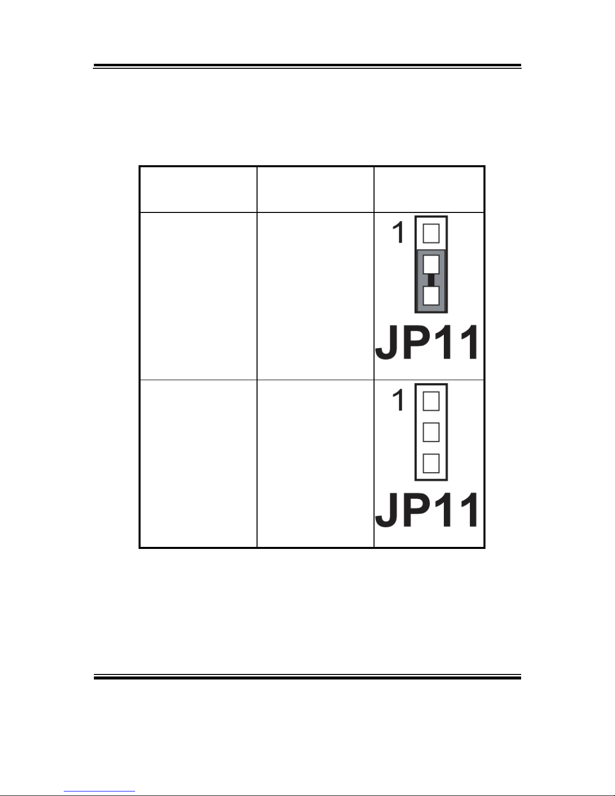
2-4. FSB FREQUENCY SELECTION
JP11: CPU FSB Frequency Selection
The selections are as follows:
SELECTION
JUMPER SETTING
(pin closed)
JUMPER
ILLUSTRATION
533 MHz 2-3
667 MHz Open
Page 18
Chapter 2 Hardware Configuration
BPC-8590 USER′S MANUAL
Page: 2-7
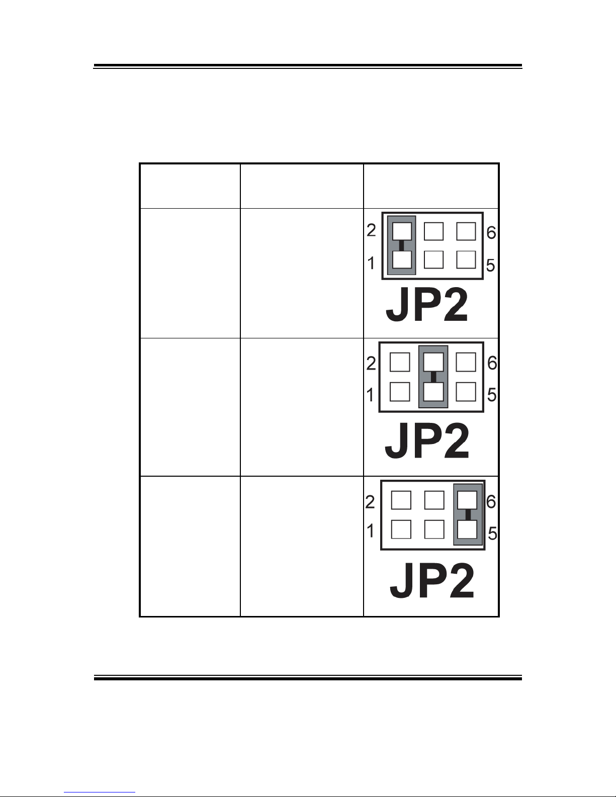
2-5. COM1 PORT RI & VOLTAGE SELECTION
JP2 : COM1 Port RI & Voltage Selection
The selections are as follows:
SELECTION
JUMPER SETTING
(Pin Closed)
JUMPER
ILLUSTRATION
RI1
1-2
+12V
3-4
+5V
5-6
***Manufacturing Default – RI1.
Page 19
Chapter 2 Hardware Configuration
Page: 2-8
BPC-8590 USER
′
S MANUAL
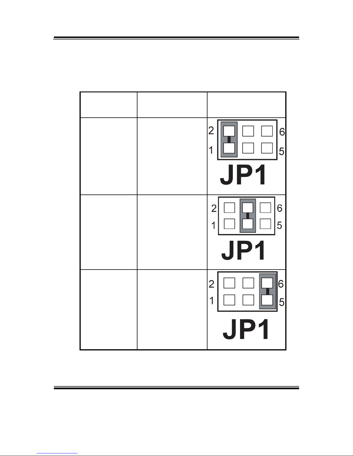
2-6. COM2 PORT RI & VOLTAGE SELECTION
JP1 : COM2 Port RI & Voltage Selection
The selections are as follows:
SELECTION
JUMPER SETTING
(Pin Closed)
JUMPER
ILLUSTRATION
RI2
1-2
+12V
3-4
+5V
5-6
***Manufacturing Default – RI2.
Page 20
Chapter 2 Hardware Configuration
BPC-8590 USER′S MANUAL
Page: 2-9
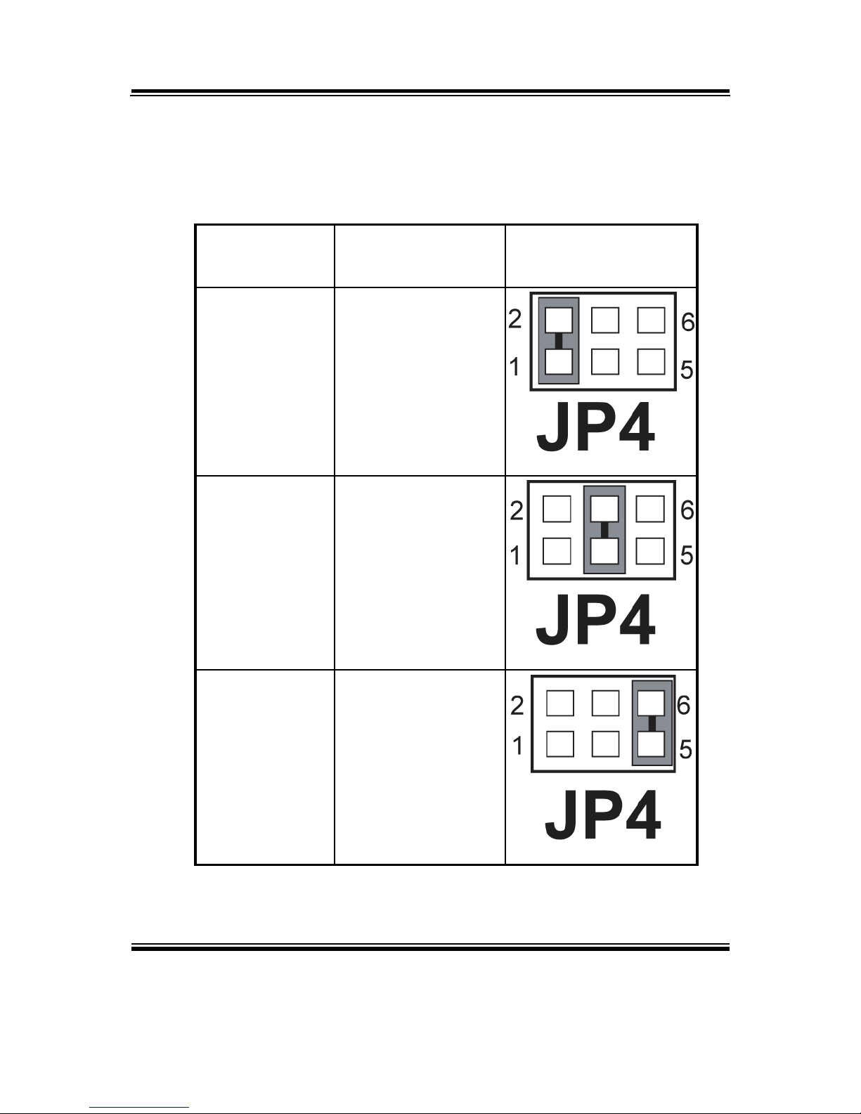
2-7. COM3 PORT RI & VOLTAGE SELECTION
JP4 : COM3 Port RI & Voltage Selection
The selections are as follows:
SELECTION
JUMPER SETTING
(Pin Closed)
JUMPER
ILLUSTRATION
RI3
1-2
+12V
3-4
+5V
5-6
***Manufacturing Default – RI3.
Page 21
Chapter 2 Hardware Configuration
Page: 2-10
BPC-8590 USER
′
S MANUAL
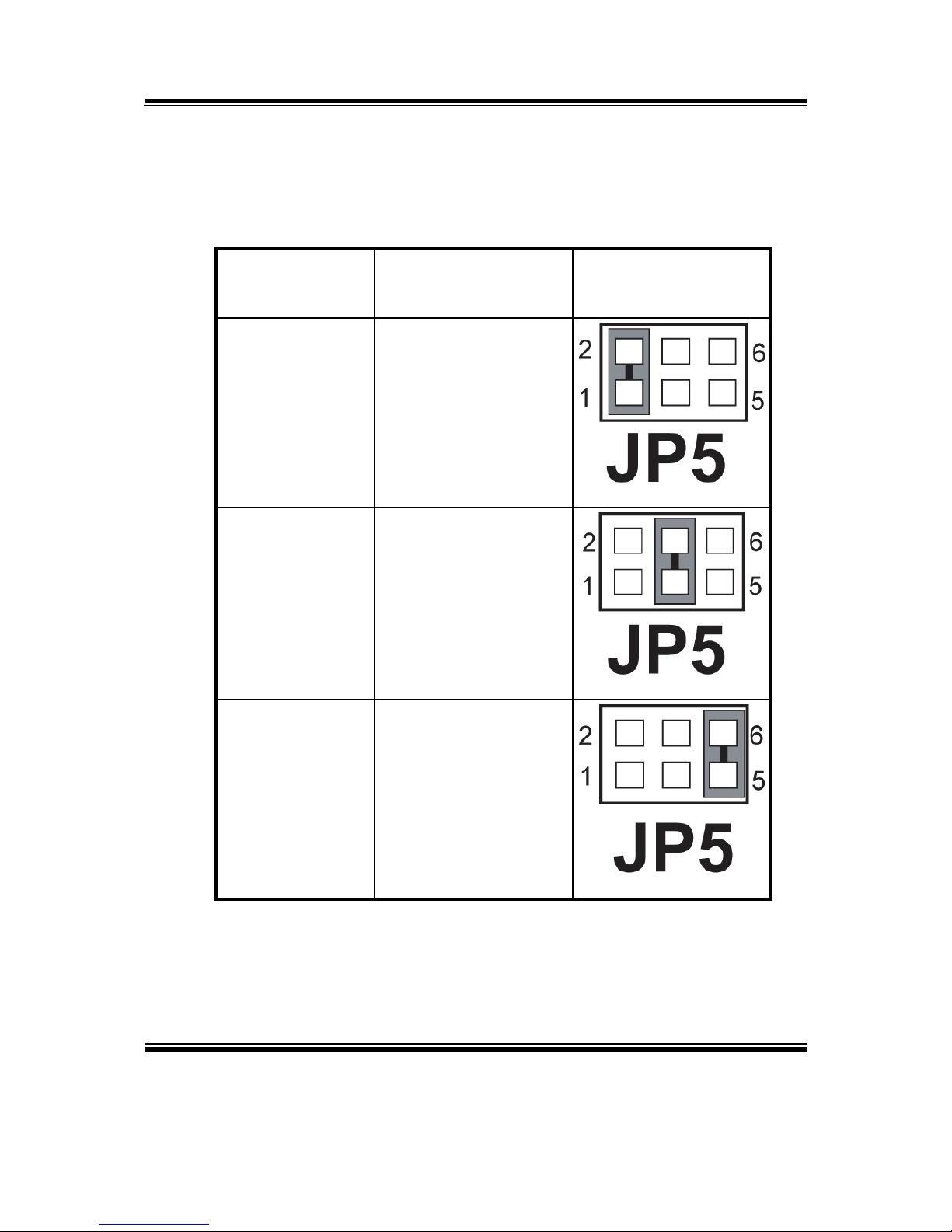
2-8. COM4 PORT RI & VOLTAGE SELECTION
JP5 : COM4 Port RI & Voltage Selection
The selections are as follows:
SELECTION
JUMPER SETTING
(Pin Closed)
JUMPER
ILLUSTRATION
RI4
1-2
+12V
3-4
+5V
5-6
***Manufacturing Default – RI4.
Page 22
Chapter 2 Hardware Configuration
BPC-8590 USER′S MANUAL
Page: 2-11
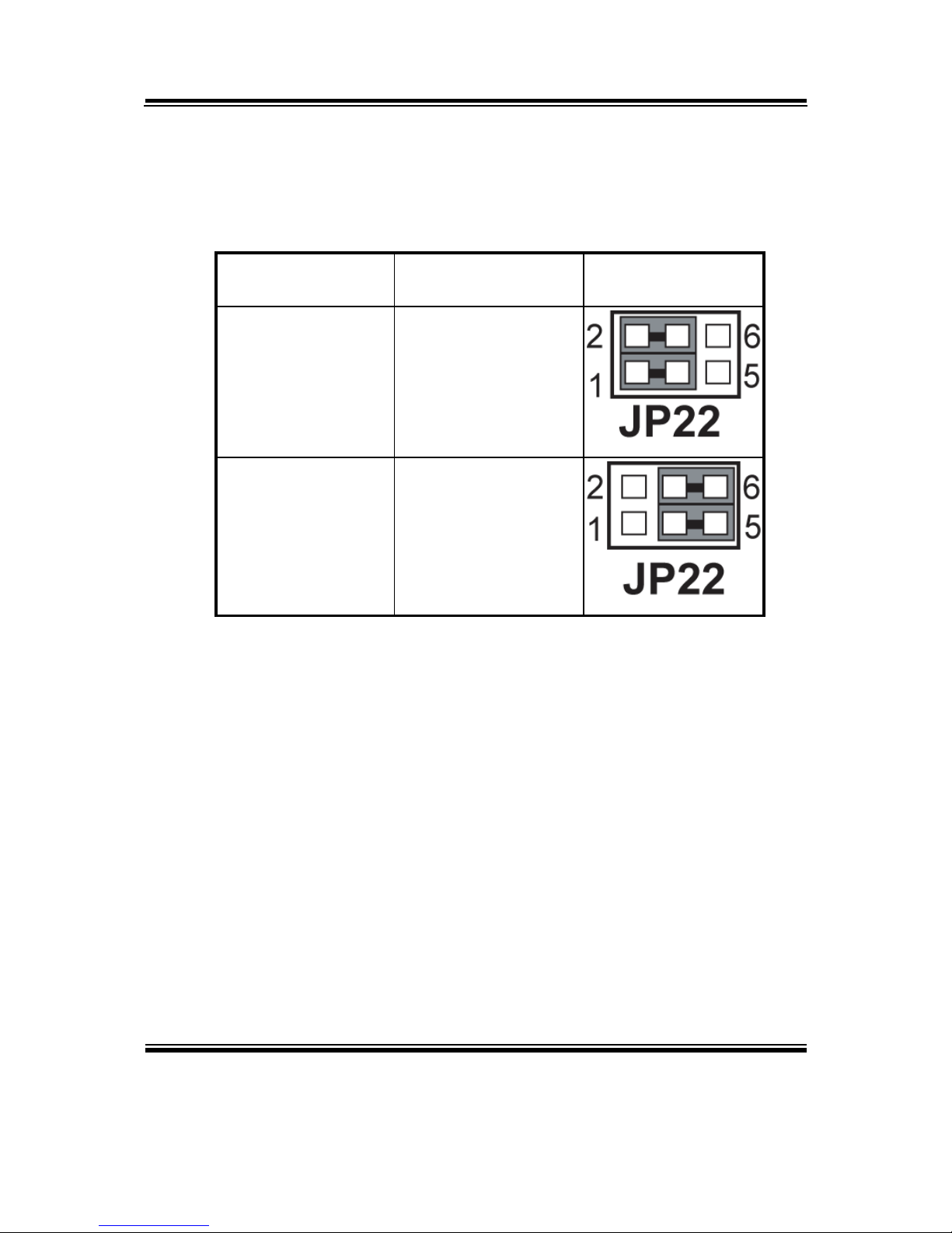
2-9. KEYBOARD/ MOUSE SELECTION
JP22 : Keyboard/ Mouse Selection.
The selections are as follows:
SELECTION JUMPER SETTING
JUMPER
ILLUSTRATION
Mouse 1-3, 2-4
Keyboard 3-5, 4-6
***Manufacturing Default –Keyboard
Page 23
Chapter 2 Hardware Configuration
Page: 2-12
BPC-8590 USER
′
S MANUAL
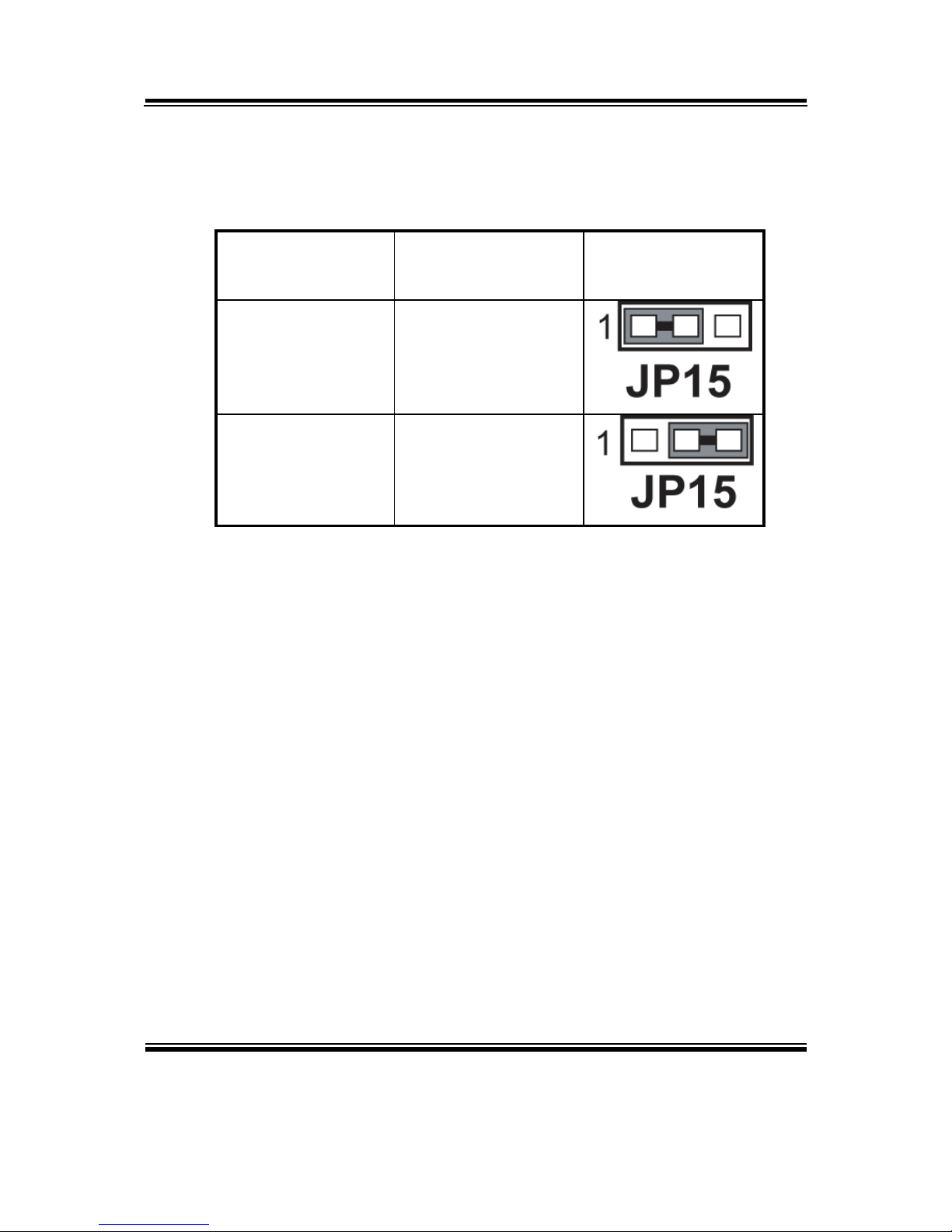
2-10. CLEAR CMOS DATA SELECTION
JP15: Clear CMOS Data Selection
The selections are as follows :
FUNCTION
JUMPER SETTING
(pin closed)
JUMPER
ILLUSTRATION
Normal 1-2
Clear CMOS 2-3
*** Manufacturing Default is set as Normal.
Note: To clear CMOS data, user must power-off the computer and set the jumper
to “Clear CMOS” as illustrated above. After five to six seconds, set the
jumper back to “Normal” and power-on the computer.
Page 24
Chapter 2 Hardware Configuration
BPC-8590 USER′S MANUAL
Page: 2-13
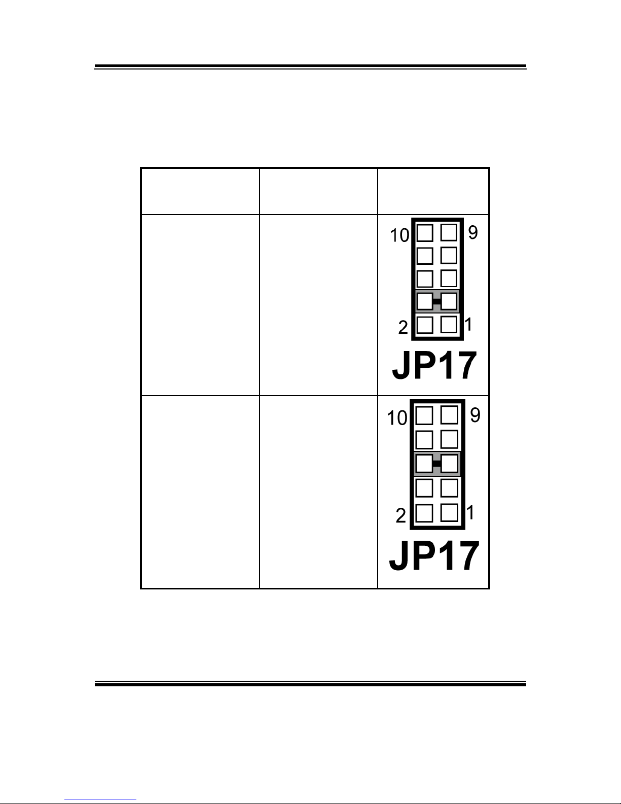
2-11. RESET/ NMI/ WATCHDOG SELECTION
JP17: Reset/ NMI/ Watchdog Selection
The selections are as follows:
SELECTION
JUMPER SETTING
(pin closed)
JUMPER
ILLUSTRATION
RESET 3-4
NMI 5-6
*** Manufacturing Default: Reset.
Page 25
Chapter 2 Hardware Configuration
Page: 2-14
BPC-8590 USER
′
S MANUAL
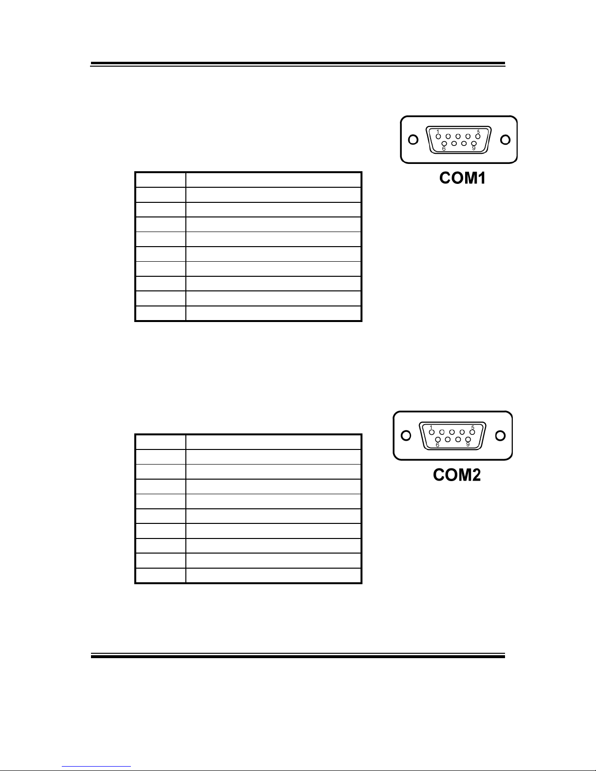
2-12 COM PORT CONNECTOR
COM1 : COM1 Connector
COM1 is fixed as RS-232.
The pin assignment is as follows :
PIN ASSIGNMENT
1 DCD
2 RX
3 TX
4 DTR
5 GND
6 DSR
7 RTS
8 CTS
9 RI1
Pin 9 is selectable for RI, +5V or +12V. For more information,
please refer to our “2-5 COM1 RI and Voltage Selection”.
COM2 : COM2 Connector
The COM2 is selectable as RS-232.
The pin assignment is as follows :
PIN ASSIGNMENT
1 DCD
2 RX
3 TX
4 DTR
5 GND
6 DSR
7 RTS
8 CTS
9 RI2
Pin 9 is selectable for RI, +5V or +12V. For more information,
please refer to our “2-6 COM2 RI and Voltage Selection”.
Page 26
Chapter 2 Hardware Configuration
BPC-8590 USER′S MANUAL
Page: 2-15
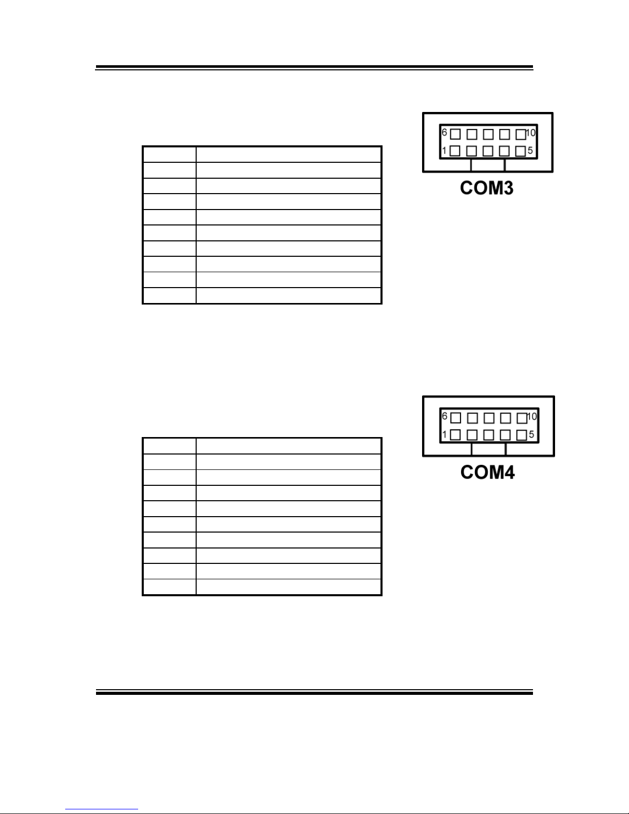
COM3 : COM3 Connector
The pin assignment is as follows :
PIN ASSIGNMENT
1 DCD
2 RX
3 TX
4 DTR
5 GND
6 DSR
7 RTS
8 CTS
9 RI3
Pin 9 is selectable for RI, +5V or +12V. For more information,
please refer to our “2-7 COM3 RI and Voltage Selection”.
COM4 : COM4 Connector
COM4 is fixed as RS-232.
The pin assignment is as follows :
PIN ASSIGNMENT
1 DCD
2 RX
3 TX
4 DTR
5 GND
6 DSR
7 RTS
8 CTS
9 RI4
Pin 9 is selectable for RI, +5V or +12V. For more information,
please refer to our “2-8 COM4 RI and Voltage Selection”.
Page 27
Chapter 2 Hardware Configuration
Page: 2-16
BPC-8590 USER
′
S MANUAL
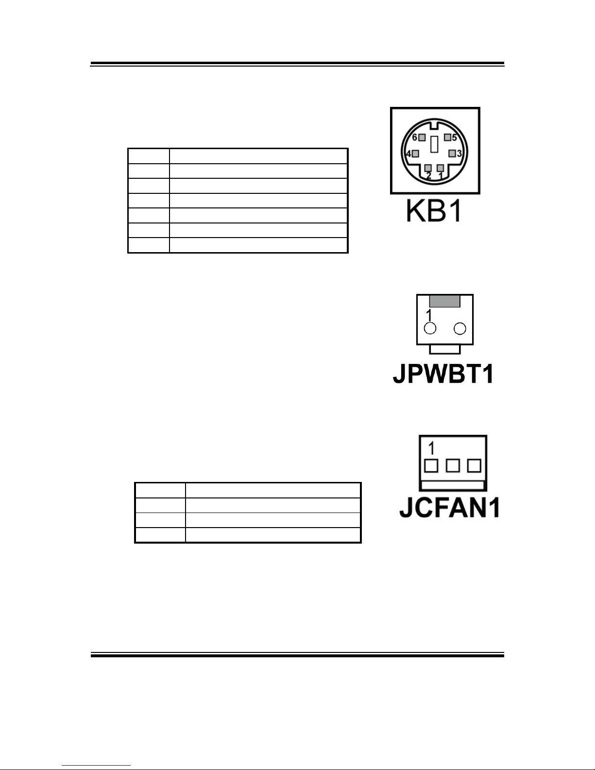
2-13. KEYBOARD/ MOUSE CONNECTOR
JDIN1 : Keyboard/ Mouse Connector
The pin assignments are as follows :
PIN ASSIGNMENT
1 KBDATA
2 MSDATA
3 GND
4 5VSB
5 KBCLK
6 MSCLK
2-14. POWER BUTTON
JPWBT1: Power Button
2-15. CPU FAN CONNECTOR
JCFAN1 : CPU Fan connector
The pin assignment is as follows:
PIN ASSIGNMENT
1 GND
2 FAN POWER
3 LPC_FAN1IN
Page 28
Chapter 2 Hardware Configuration
BPC-8590 USER′S MANUAL
Page: 2-17
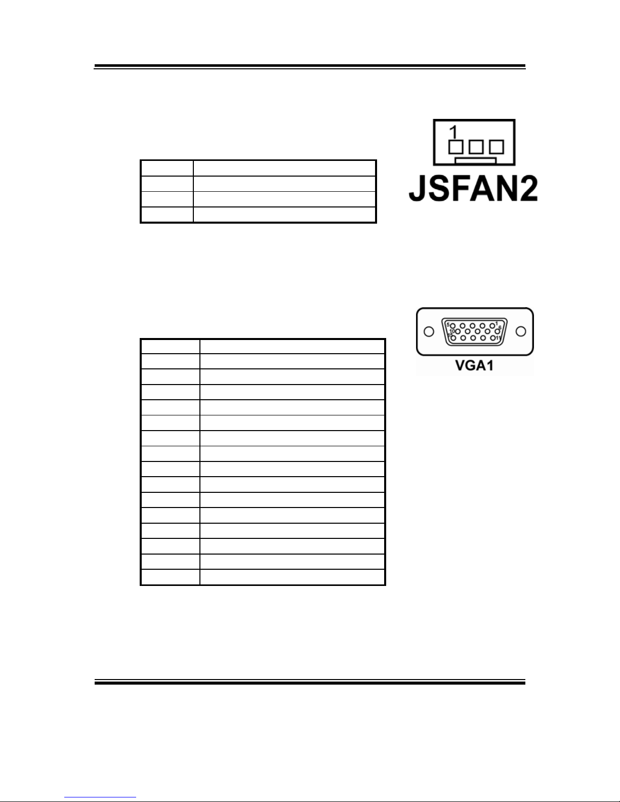
2-16. SYSTEM FAN CONNECTOR
JSFAN2 : System Fan connector
The pin assignment is as follows:
PIN ASSIGNMENT
1 GND
2 VCC12
3 LPC_FAN2IN
2-17. VGA CONNECTOR
VGA1: VGA Connector
The pin assignments are as follows:
PIN ASSIGNMENT
1 RED
2 GREEN
3 BLUE
4 NC
5 GND
6 GND
7 GND
8 GND
9 VGA_VCC5
10 GND
11 NC
12 DDC_DATA
13 HSYNC
14 VSYNC
15 DDC_CLK
Page 29
Chapter 2 Hardware Configuration
Page: 2-18
BPC-8590 USER
′
S MANUAL
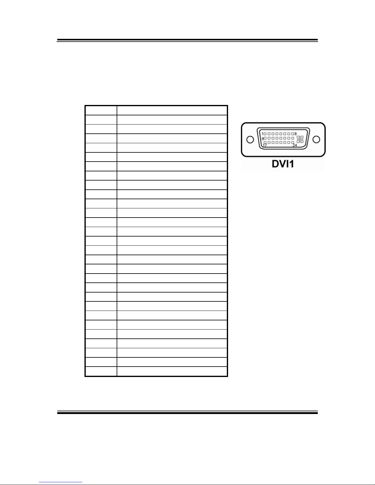
2-18. DVI CONNECTOR
DVI1 : DVI Connector.
The pin assignments are as follows:
PIN ASSIGNMENT
1 TDC2J
2 TDC2
3 GND
4 NC
5 NC
6 SC_DDC
7 SD_DDC
8 A_VSYNC
9 TDC1J
10 TDC1
11 GND
12 NC
13 NC
14 VCC5
15 GND
16 Hot Plug Detect
17 TDC0J
18 TDC0
19 GND
20 NC
21 NC
22 GND
23 TLC
24 TLCJ
C1 A_RED
C2 A_GREEN
C3 A_BLUE
C4 A_HSYNC
Page 30
Chapter 2 Hardware Configuration
BPC-8590 USER′S MANUAL
Page: 2-19
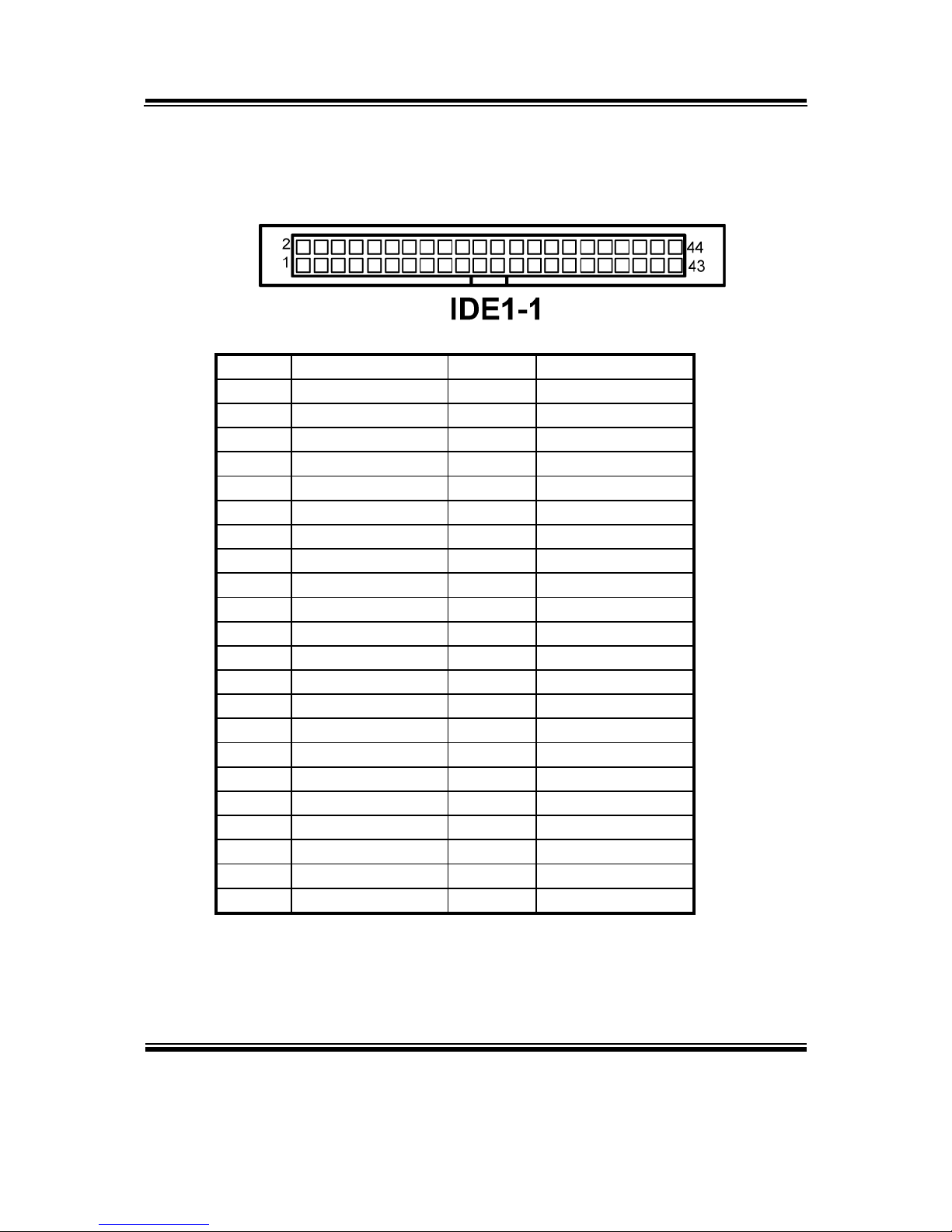
2-19. HARD DISK DRIVE CONNECTOR
IDE-11: Hard Disk Drive Connector
The pin assignments are as follows:
PIN ASSIGNMENT PIN ASSIGNMENT
1 IDERST# 23 P DIOW#
2 GND 24 GND
3 PDD7 25 P DIOR#
4 PDD8 26 GND
5 PDD6 27 PIORDY
6 PDD9 28 GND
7 PDD5 29 PDDACK#
8 PDD10 30 GND
9 PDD4 31 IRQ14
10 PDD11 32 NC
11 PDD3 33 PDA1
12 PDD12 34 P66DETECT
13 PDD2 35 PDA0
14 PDD13 36 PDA2
15 PDD1 37 PDCS#1
16 PDD14 38 PDCS#3
17 PDD0 39 IDEACTP#
18 PDD15 40 GND
19 GND 41 VCC
20 NC 42 VCC
21 PDREQ 43 GND
22 GND 44 NC
Page 31
Chapter 2 Hardware Configuration
Page: 2-20
BPC-8590 USER
′
S MANUAL
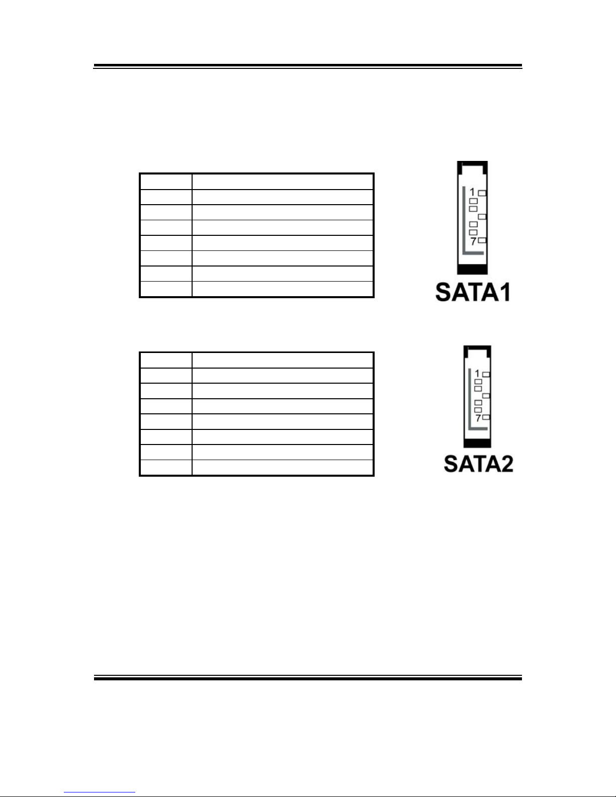
2-20. SERIAL ATA CONNECTOR
SATA1, SATA2: The BPC-8590 possesses two Serial ATA Connector.
The pin assignments are as follows:
SATA1:
PIN ASSIGNMENT
1 GND
2 SATAHDR_TXP0
3 SATAHDR_TXN0
4 GND
5 SATAHDR_RXN0
6 SATAHDR_RXP0
7 GND
SATA2:
PIN ASSIGNMENT
1 GND
2 SATAHDR_TXP1
3 SATAHDR_TXN1
4 GND
5 SATAHDR_RXN1
6 SATAHDR_RXP1
7 GND
Page 32
Chapter 2 Hardware Configuration
BPC-8590 USER′S MANUAL
Page: 2-21
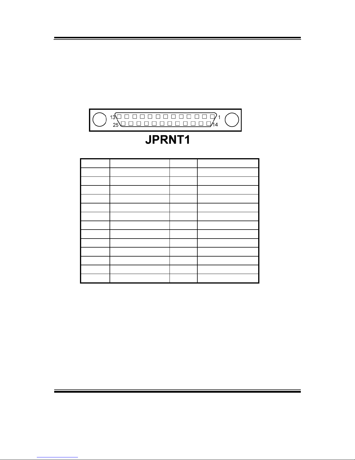
2-21. PRINTER CONNECTOR
JPRT1: Printer Connector
As to link the Printer to the card, you need a cable to connect both
DB25 connector and parallel port.
The pin assignments are as follows :
PIN ASSIGNMENT PIN ASSIGNMENT
1 STB 14 AUTFE
2 P0 15 ERROR
3 P1 16 INIT
4 P2 17 SLCTIN
5 P3 18 GND
6 P4 19 GND
7 P5 20 GND
8 P6 21 GND
9 P7 22 GND
10 ACK 23 GND
11 BUSY 24 GND
12 PE 25 GND
13 SLCT
Page 33
Chapter 2 Hardware Configuration
Page: 2-22
BPC-8590 USER
′
S MANUAL
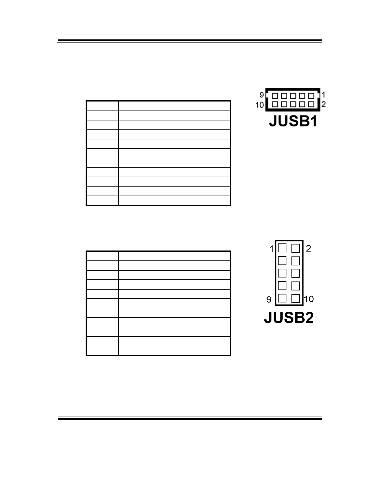
2-22. UNIVERSAL SERIAL BUS CONNECTOR
JUSB1: Universal Serial Bus Connector
The pin assignments are as follows:
PIN ASSIGNMENT
1 USB2_VCC5
2 USB3_VCC5
3 USBN2_L
4 USBN3_L
5 USBP2_L
6 USBP3_L
7 GND
8 GND
9 GND
10 GND
JUSB2: Universal Serial Bus Connector
The pin assignments are as follows:
PIN ASSIGNMENT
1 USB2_VCC5
2 USB3_VCC5
3 USBN2_L
4 USBN3_L
5 USBP2_L
6 USBP3_L
7 GND
8 GND
9 GND
10 GND
Page 34
Chapter 2 Hardware Configuration
BPC-8590 USER′S MANUAL
Page: 2-23
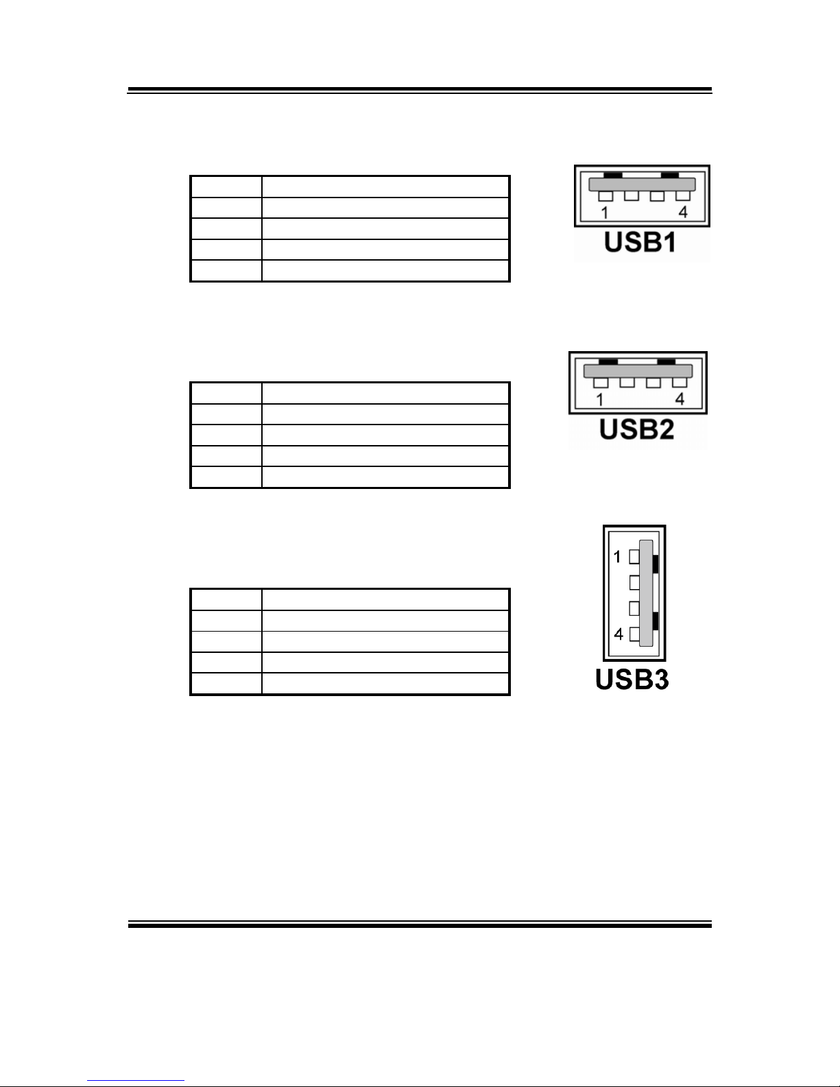
USB1: Universal Serial Bus Connector
The pin assignments are as follows:
PIN ASSIGNMENT
1 VCC
2 USBP03 USBP0+
4 GND
USB2: Universal Serial Bus Connector
The pin assignments are as follows:
PIN ASSIGNMENT
1 VCC
2 USBP03 USBP0+
4 GND
USB3: Universal Serial Bus Connector
The pin assignments are as follows:
PIN ASSIGNMENT
1 VCC
2 USBP03 USBP0+
4 GND
Page 35
Chapter 2 Hardware Configuration
Page: 2-24
BPC-8590 USER
′
S MANUAL
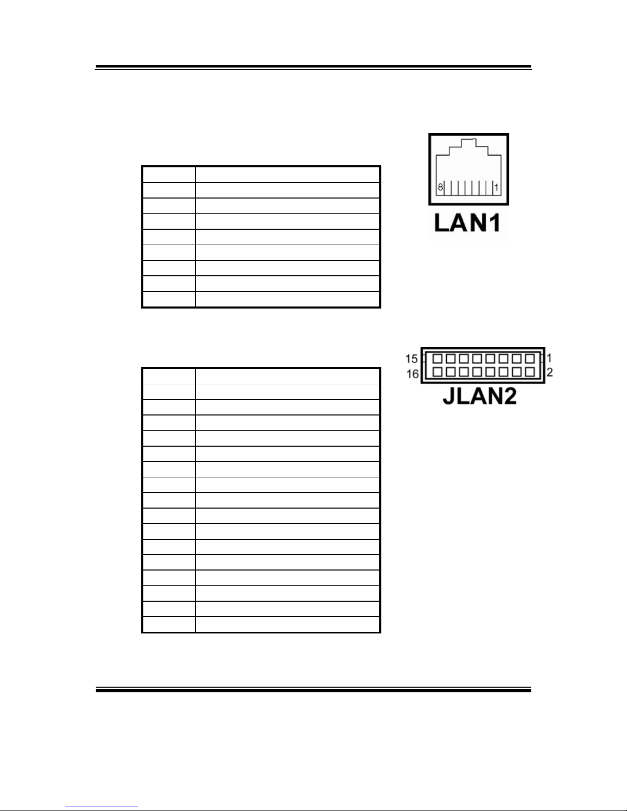
2-23. LAN CONNECTOR
LAN1: LAN Connector.
The pin assignment is as follows :
PIN ASSIGNMENT
1 MDI_0P
2 MDI_0N
3 MDI_1P
4 MDI_1N
5 MDI_2P
6 MDI_2N
7 MDI_3P
8 MDI_3N
JLAN2: LAN Connector.
The pin assignment is as follows :
PIN ASSIGNMENT
1 1MDI_3+
2 1MDI_33 1MDI_2+
4 1MDI_25 1MDI_1+
6 1MDI_17 1MDI_0+
8 1MDI_0-
9 VCC25-CG
10 GND
11 1VCC3.3R
12 GND
13 1LINK-R
14 1ACT
15 1SPEED100
16 1SPEED1000-R
Page 36
Chapter 2 Hardware Configuration
BPC-8590 USER′S MANUAL
Page: 2-25
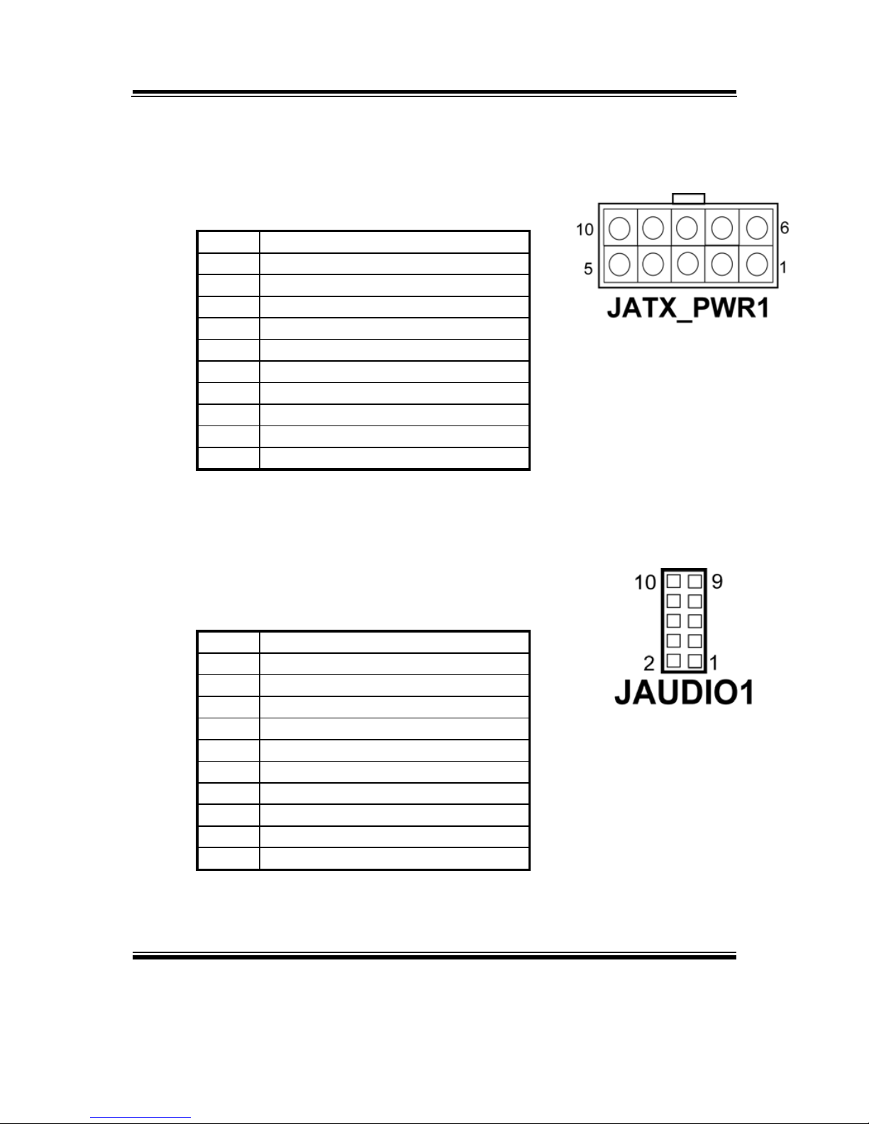
2-24. ATX POWER CONNECTOR
JATX_PWR1 : ATX Power Connector
The pin assignments are as follows:
PIN ASSIGNMENT
1 VCC
2 VCC
3 GROUND
4 GROUND
5 +12V
6 VCC SBY
7 VCC
8 GROUND
9 PS_ON
10 -12V
2-25. AUDIO CONNECTOR
JAUDIO1 : Audio Connector
The pin assignments are as follows:
PIN ASSIGNMENT
1 MIC_IN
2 NC
3 GND
4 GND
5 LINE-L
6 LINE-R
7 GND
8 GND
9 SPK-L
10 SPK-R
Page 37
Chapter 2 Hardware Configuration
Page: 2-26
BPC-8590 USER
′
S MANUAL
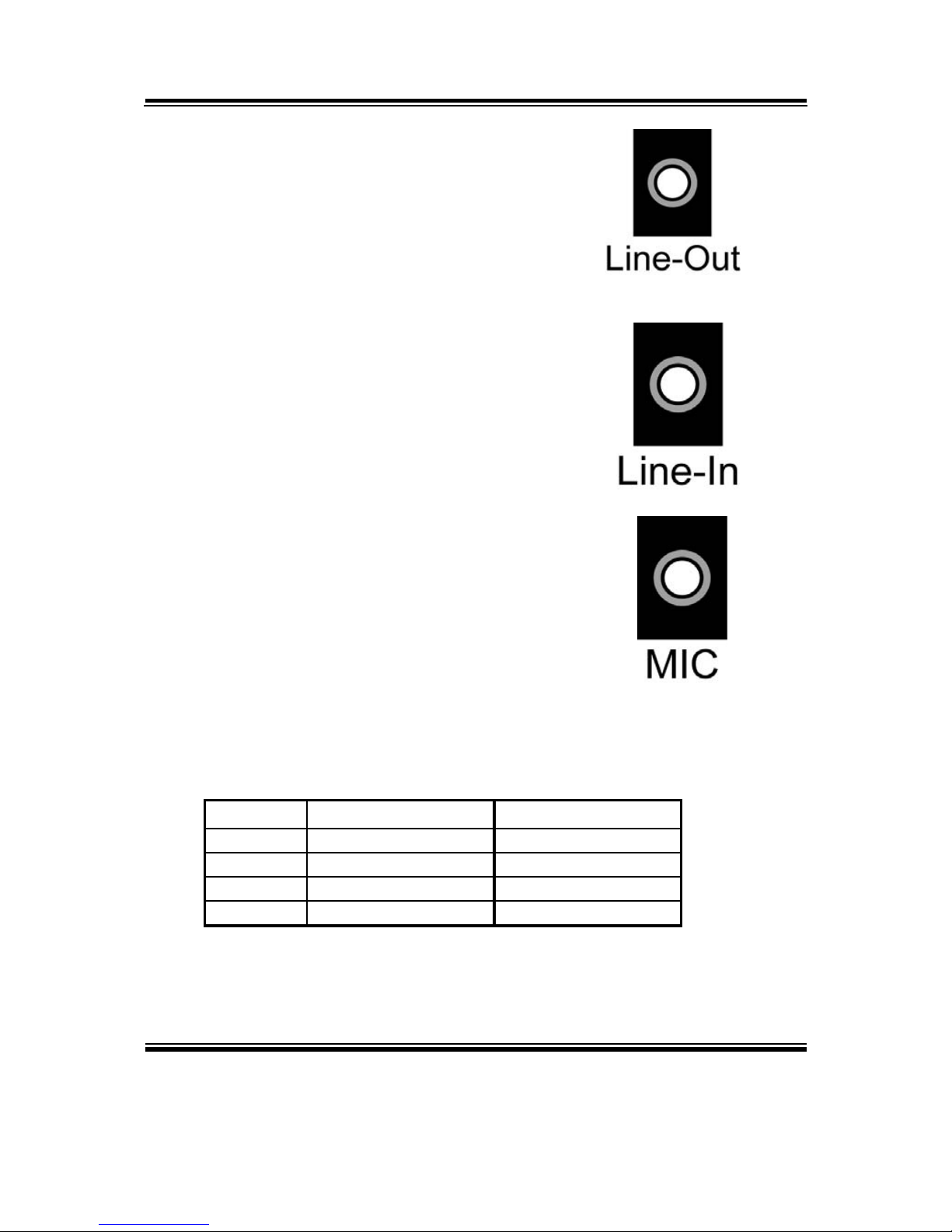
2-26. LINE-OUT CONNECTOR
LINE-OUT1 : Line-Out Connector
2-27. LINE-IN CONNECTOR
LINE-IN1 : Line-In Connector
2-28. MIC CONNECTOR
MIC1 : MIC Connector
2-29. MEMORY INSTALLATION
BPC-8590 CPU Card can support up to 1GB in one DIMM socket.
DIMM 1 DIMM 2 TOTAL MEMORY
128MB 128MB 256MB
256MB 256MB 512MB
512MB 512MB 1GB
1GB 1GB 2GB
Page 38

Chapter 2 Hardware Configuration
BPC-8590 USER′S MANUAL
Page: 2-27
2-30. PCI CONNECTOR
PCI1 : PCI Connector.
The pin assignments are as follow:
PCI1
B A B A
PIN ASSIGNMENT PIN ASSIGNMENT PIN ASSIGNMENT PIN ASSIGNMENT
B1 -12V A1 TRST# B31 +3.3V A31 AD18
B2 TCK A2 +12V B32 AD17 A32 AD16
B3 GND A3 TMS B33 C/BE2# A33 +3.3V
B4 TDO A4 TDI B34 GND A34 FRAME#
B5 +5V A5 +5V B35 IRDY# A35 GND
B6 +5V A6 INTA# B36 +3.3V A36 TRDY#
B7 INTB# A7 INTC# B37 DEVSEL# A37 GND
B8 INTD# A8 +5V B38 GND A38 STOP#
B9 REQ3# A9 CLKC B39 LOCK# A39 +3.3V
B10 REQ1# A10 +5V(I/O) B40 PERR# A40 SDONE
B11 GNT3# A11 CLKD B41 +3.3V A41 SB0#
B12 GND A12 GND B42 SERR# A42 GND
B13 GND A13 GND B43 +3.3V A43 PAR
B14 CLKA A14 GNT1# B44 C/BE1# A44 AD15
B15 GND A15 RST# B45 AD14 A45 +3.3V
B16 CLKB A16 +5V(I/O) B46 GND A46 AD13
B17 GND A17 GNT0# B47 AD12 A47 AD11
B18 REQ0# A18 GND B48 AD10 A48 GND
B19 +5V(I/O) A19 REQ2# B49 GND A49 AD09
B20 AD31 A20 AD30 B52 AD08 A52 C/BE0#
B21 AD29 A21 +3.3V B53 AD07 A53 +3.3V
B22 GND A22 AD28 B54 +3.3V A54 AD06
B23 AD27 A23 AD26 B55 AD05 A55 AD04
B24 AD25 A24 GND B56 AD03 A56 GND
B25 +3.3V A25 AD24 B57 GND A57 AD02
B26 C/BE3# A26 GNT2# B58 AD01 A58 AD00
B27 AD23 A27 +3.3V B59 +5V(I/O) A59 +5V(I/O)
B28 GND A28 AD22 B60 ACK64# A60 REQ64#
B29 AD21 A29 AD20 B61 +5V A61 +5V
B30 AD19 A30 GND B62 +5V A62 +5V
Page 39

Page: 3-1
SOFTWARE
UTILITIES
This chapter comprises the detailed information of VGA driver,
LAN driver, Sound driver, and flash BIOS update. It also describes
on how to install the watchdog timer.
Section includes:
z VGA Driver Utility
z Flash BIOS Update
z LAN Driver Utility
z SOUND Driver Utility
z Intel® Chipset Software Installation Utility
z Watchdog Timer Configuration
CHAPTER
3
Page 40

Chapter 3 Software Configuration
Page:3-2
BPC-8590 USER
′
S MANUAL
3-1. INTRODUCTION
Enclosed with our BPC-8590 package, you will find a CD ROM disk
containing all types of drivers we have. As a BPC-8590 user, you will only
need the some of files contained in the CD ROM disk, please take note of the
following chart :
File name
(Assume that CD ROM drive is D:)
Purpose
D:\Driver\VGA Intel 945 GM
For VGA driver installation
D:\Driver\FLASH For BIOS update utility
D:\Driver\LAN For LAN Driver installation
D:\Driver\Sound Realtek ALC655 AC97
For Sound driver installation
D:\Driver\UTILITY Intel® Chipset Software
Installation Utility
For Win 2000, XP
User should remember to install the Utility right after the OS fully installed.
Page 41
Chapter 3 Software Configuration
BPC-8590 USER′S MANUAL
Page:3-3
3-2. VGA DRIVER UTILITY
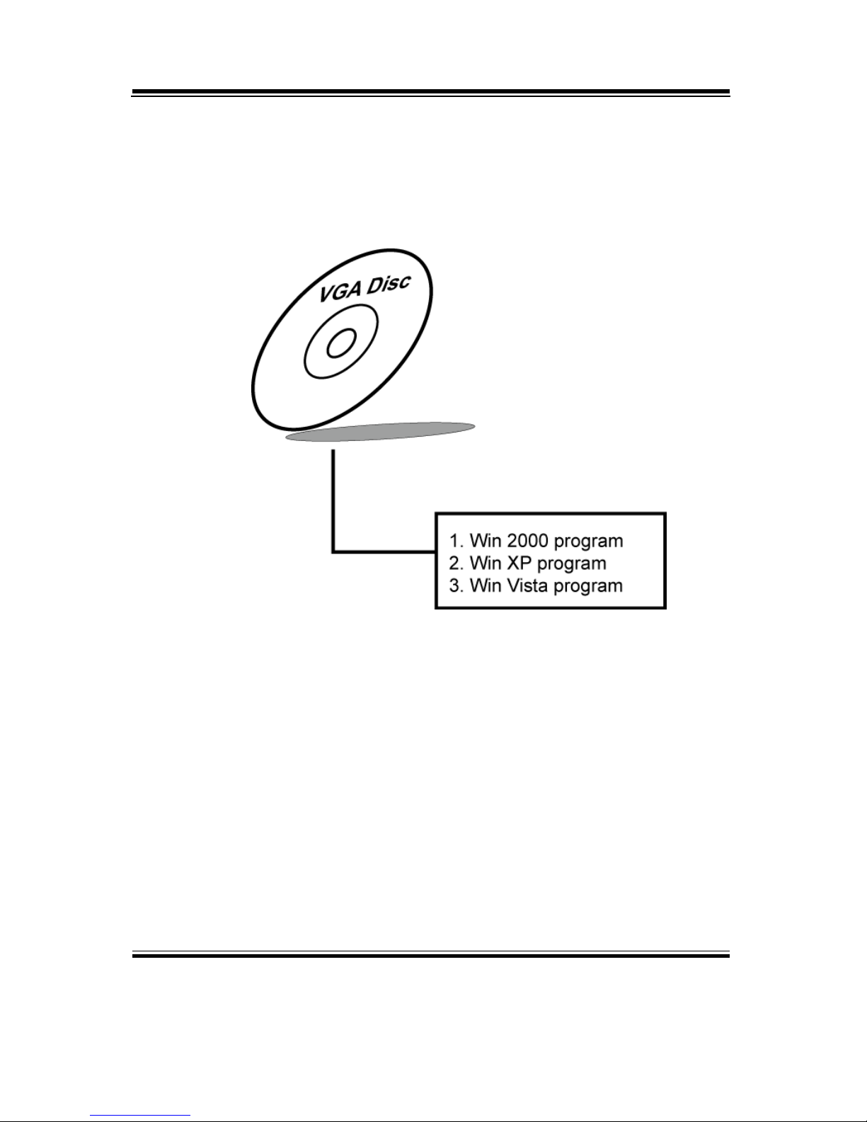
The VGA interface is embedded with our BPC-8590 system to support CRT
display. The following illustration briefly shows you the content of VGA
driver in D:\VGA\:
3-2-1. Installation of VGA Driver
(1) Start the computer (Win 2000/XP/Vista).
(2) Insert the Utility Disk into the CD ROM drive or drive A/B.
(3) Double-click “D:\VGA\WIN9X\SETUP.EXE
(if D is not your CD ROM drive and substitute D with th e righ t d riv e) in
the text entry area and press OK.
(4) Click “Next” on the Welcome screen.
(5) Read the license agreement and click “Yes” to continue.
(6) The driver files will now be installed. When finished, choose the
“Yes” to reboot option, and click “Finished” to restart your computer.
The driver should now be loaded.
For more information on VGA driver installation, please refer to the
readme.txt found on the sub-directory of the VGA driver utility.
Page 42

Chapter 3 Software Configuration
Page:3-4
BPC-8590 USER
′
S MANUAL
3-3. FLASH BIOS UPDATE
3-3-1. System BIOS Update:
Users of BPC-8590 can use the program “Awdflash.exe” contained in
the Utility Disk for system BIOS update.
1. Install “Awdflash.exe” from Utility Disk to Drive D.
2. Insert the BIOS file you have obtained from the vendor.
Type the path to Awdflash.exe and execute the BIOS update with
file 8590xxxx.bin
3. D:\AWDFLASH>AWDFLASH 8590xxxx.bin
4. The screen will display as the table fount on the next page:
FLASH MEMORY WRITER v7.XX
(C) Award Software 2001 All Rights Reserved
Flash Type – SST 49LF004A /3.3V
File Name to Program: 8590xxxx.bin
Checksum: XXXXX
Error Message: Do You Want To Save BIOS (Y/N)
If you want to save up the original BIOS, enter "Y" and press < Enter >.
If you choose "N", the following table will appear on screen.
Page 43

Chapter 3 Software Configuration
BPC-8590 USER′S MANUAL
Page:3-5
FLASH MEMORY WRITER v7.XX
(C) Award Software 2001 All Rights Reserved
Flash Type – SST 49LF004A /3.3V
File Name to Program: 8590xxxx.bin
Checksum: XXXXX
Error Message : Are You Sure To Program (Y/N)
Select "Y", and the BIOS will be renewed. When you are refreshing the
BIOS, do not turn off or reset the system, or you will damage the BIOS.
After you have completed all the programming, the screen displays the
table below:
FLASH MEMORY WRITER v7.XX
(C) Award Software 2001 All Rights Reserved
Flash Type – SST 49LF004A /3.3V
File Name to Program: 8590xxxx.bin
Checksum: XXXXX
Reset System or Power off to
accomplish update process!
F1: Reset F10: Exit
Please reset or power off the system, and then the Flash BIOS is fully
implemented.
Page 44
Chapter 3 Software Configuration
Page:3-6
BPC-8590 USER
′
S MANUAL
3-4. LAN DRIVER UTILITY
3-4-1. Introduction
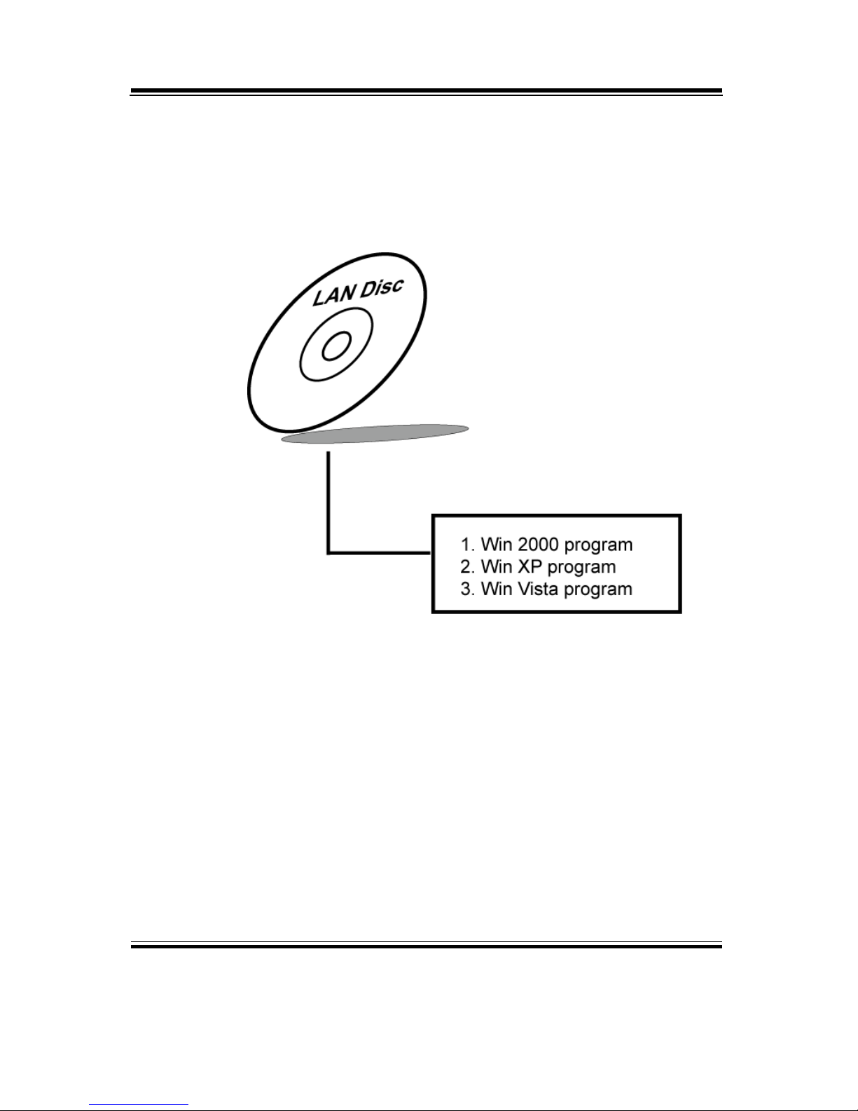
The BPC-8590 is enhanced with LAN function that can support various
network adapters. The content of the LAN driver is found as follows:
For more details on Installation procedure, please refer to Readme.txt
file found on LAN DRIVER UTILITY.
Page 45
Chapter 3 Software Configuration
BPC-8590 USER′S MANUAL
Page:3-7
3-5. SOUND DRIVER UTILITY
3-5-1. Introduction
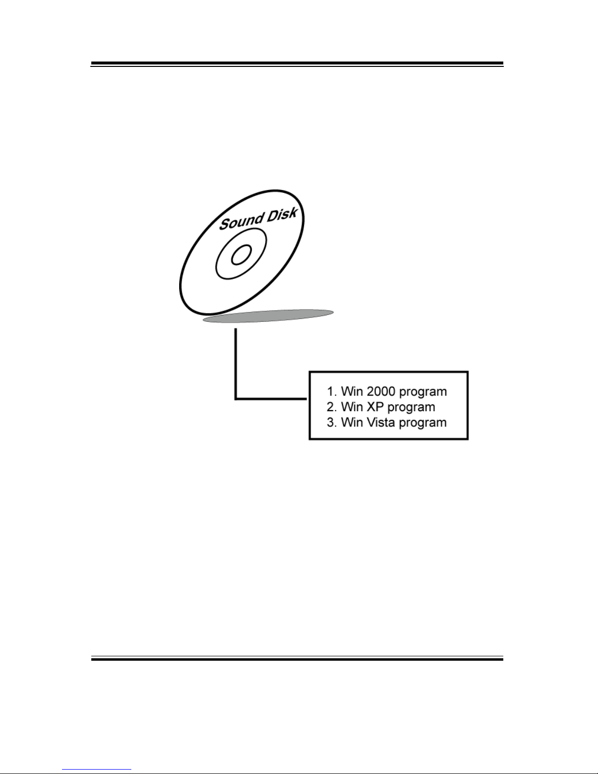
The ALC655 sound function enhanced in this system is fully compatible
with Windows 2000, Windows XP and Windows Vista. Below, you will
find the content of the Sound driver :
3-5-2. Installation Procedure for Windows2000/XP/Vista
(1) From the task bar, click on Start, and then Run.
(2) In the Run dialog box, type D:\Driver\Sound\path\setup, where
“D:\Driver\Sound\path” refers to the full path to the source files.
(3) Click on the OK button or press the ENTER key.
(4) Click on the “Next” and OK prompts as they appear.
(5) Reboot the system to complete the driver installation.
Page 46

Chapter 3 Software Configuration
Page:3-8
BPC-8590 USER
′
S MANUAL
3-6. INTEL® CHIPSET SOFTWARE INSTALLATION UTILITY
3-6-1. Introduction
The Intel® Chipset Software Installation Utility installs to the target
system the Windows* INF files that outline to the operating system how
the chipset components will be configured. This is needed for the
proper functioning of the following features:
- Core PCI and ISAPNP Services
- AGP Support
- IDE/ATA33/ATA66/ATA100 Storage Support
- USB Support
- Identification of Intel® Chipset Components in Device Manager
3-6-2. Installation of Utility for Windows 2000/XP/Vista
The Utility Pack is to be installed only for Windows 2000 and XP
program.
It should be installed right after the OS installation, kindly follow the
following steps:
1. Place insert the Utility Disk into Floppy Disk Drive A/B or CD
ROM drive.
2. Under Windows 2000/XP/Vista system, go to the directory where
Utility Disc is located.
3. Click Setup.exe file for utility installation.
4. Follow the instructions on the screen to complete the installation.
5. Once installation is completed, shut down the system and restart in
order for the changes to take effect.
Page 47

Chapter 3 Software Configuration
BPC-8590 USER′S MANUAL
Page:3-9
3-7. WATCHDOG TIMER CONFIGURATION
The Watch-dog Timer has a programmable time-out ranging from 1 to 255 minutes
with one minute resolution, or 1 to 255 seconds with 1 second resolution. The units of
the WDT timeout value are selected via bit [7] of the WDT_TIMEOUT register,
which is located on I/O Port address 0x865h. The WDT time-out value is set through
the WDT_VAL Runtime register, which is located on I/O Port address 0x866h.
Setting the WDT_VAL register to 0x00 disables the WDT function Setting the
WDT_VAL to any other non-zero value will cause the WDT to reload and begin
counting down from the value loaded. Setting the Register located on I/O address
0x867h and 0x868h as 00h to finish timer configuration.
Example Program
Example Code:
(1)
; -----------------------------------------------------------------------------------------------; Enable Watch-Dog Timer
;------------------------------------------------------------------------------------------------ mov dx, (800h+65h) ; Time counting Unit minute or second
mov al, 80h ; al = 00h : minute, or al = 80h : second
out dx, al
mov dx, (800h+66h)
mov al, 20 ; al = Watch Dog Timer Second (s) , 20 sec (s)
out dx, al
mov dx, (800h+67h)
mov al, 00h
out dx, al
mov dx, (800h+68h) ; Start Watch Dog Timer
mov al, 00h
out dx, al
(2)
;-------------------------------------------------------------------------------------------------; Disable Watch-Dog Timer
;------------------------------------------------------------------------------------------------- mov dx, (800h+66h) ; Disabled Watch Dog
mov al, 00h
out dx, al
mov dx, (800h+67h)
mov al, 00h
out dx, al
mov dx, (800h+68h) ; Clear Status Bit
mov al, 00h
out dx, al
Page 48

Page: 4-1
AWARD
BIOS SETUP
This chapter shows how to set up the Phoenix Award BIOS.
Section includes:
z Introduction
z Entering Setup
z The Standard CMOS Features
z The Advanced BIOS Features
z The Advanced Chipset Features
z Integrated Peripherals
z Power Management Setup
z PNP/PCI Configuration
z PC Health Status
z Load Fail-Safe Defaults
z Load Optimized Defaults
z Password Setting
z Save and Exit Setup
z Exit Without Saving
CHAPTER
4
Page 49
Chapter 4 Award BIOS Setup
Page: 4-2
BPC-8590 USER
′
S MANUAL
4-1. INTRODUCTION
This chapter will show you the function of the BIOS in managing the
features of your system. The BPC-8590 Core 2 Duo Book Size PC is
equipped with the BIOS for system chipset from Award Software Inc. This
page briefly explains the function of the BIOS in managing the special
features of your system. The following pages describe how to use the BIOS
for system chipset Setup menu.
Your application programs (such as word processing, spreadsheets, and
games) rely on an operating system such as DOS or OS/2 to manage such
things as keyboard, monitor, disk drives, and memory.
The operating system relies on the BIOS (Basic Input and Output system), a
program stored on a ROM (Read-only Memory) chip, to initialize and
configure your computer's hardware. As the interface between the hardware
and the operating system, the BIOS enables you to make basic changes to
your system's hardware without having to write a new operating system.
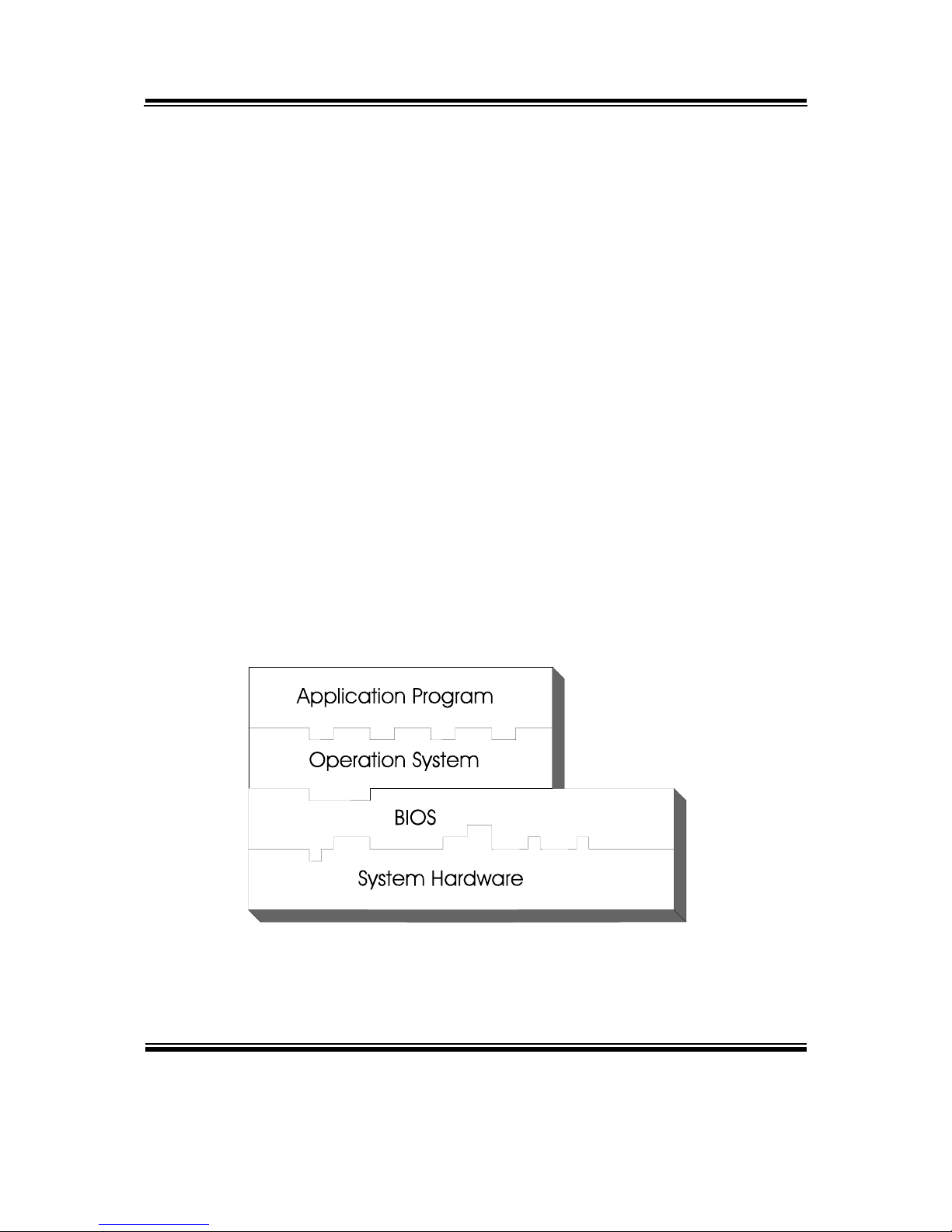
The following diagram illustrates the interlocking relationships between the
system hardware, BIOS, operating system, and application program:
Page 50

Chapter 4 Award BIOS Setup
BPC-8590 USER′S MANUAL
Page: 4-3
4-2. ENTERING SETUP
When the system is powered on, the BIOS will enter the Power-On Self
Test (POST) routines and the following message will appear on the lower
screen:
PRESS <DEL> TO ENTER SETUP, ESC TO SKIP MEMORY TEST
As long as this message is present on the screen you may press the <Del>
key (the one that shares the decimal point at the bottom of the number
keypad) to access the Setup program. In a moment, the main menu of the
Award SETUP program will appear on the screen:
Phoenix - AwardBIOS CMOS Setup Utility
►Standard CMOS Features
►Advanced BIOS Features
►Advanced Chipset Features
►Integrated Peripherals
►Power Management Setup
►PnP/PCI Configurations
►PC Health Status
Load Fail-Safe Defaults
Load Optimized Defaults
Set Supervisor Password
Set User Password
Save & Exit Setup
Exit Without Saving
Esc : Quit ↑↓→← : Select Item
F10 : Save & Exit Setup
Time, Date, Hard Disk Type .…
Setup program initial screen
You may use the cursor the up/down keys to highlight the individual menu
items. As you highlight each item, a brief description of the highlighted
selection will appear at the bottom of the screen.
Page 51

Chapter 4 Award BIOS Setup
Page: 4-4
BPC-8590 USER
′
S MANUAL
4-3. THE STANDARD CMOS FEATURES
Highlight the〝STANDARD CMOS FEATURES〞and press the <ENTER>
key and the screen will display the following table:
Phoenix - AwardBIOS CMOS Setup Utility
Standard CMOS Features
Date (mm:dd:yy)
Time (hh:mm:ss)
Sun, Jan
14 2007
0 : 6 : 34
Item Help
▶ IDE Channel 0 Master
▶ IDE Channel 0 Slave
▶ IDE Channel 1 Master
▶ IDE Channel 1 Slave
Drive A
Halt On
Base Memory
Extended Memory
Total Memory
[ None]
[ None]
[ None]
[ None]
[1.44M, 3.5 in.]
[All Errors]
640K
1038336K
1039360K
Menu Level ►
Change the day,
month, year and
century
↑↓→←: Move Enter: Select +/-/PU/PD:Value F10:Save ESC:Exit F1:General Help
F5: Previous Values F6: Fail-Safe Defaults F7:Optimized Defaults
CMOS Setup screen
In the above Setup Menu, use the arrow keys to highlight the item and then use
the <PgUp> or <PgDn> keys to select the value you want in each item.
Date:
< Month >, < Date > and <Year >. Ranges for each value are in the CMOS
Setup Screen, and the week-day will skip automatically.
Time:
< Hour >, < Minute >, and < Second >. Use 24 hour clock format, i.e., for PM
numbers, add 12 to the hour. For example: 4: 30 P.M. You should enter the
time as 16:30:00.
Page 52

Chapter 4 Award BIOS Setup
BPC-8590 USER′S MANUAL
Page: 4-5
IDE Primary Master / Slave:
IDE Secondary Master / Slave:
The BIOS can automatically detect the specifications and optimal operating
mode of almost all IDE hard drives. When you select type AUTO for a hard
drive, the BIOS detect its specifications during POST, every time system
boots.
If you do not want to select drive type AUTO, other methods of selecting
drive type are available:
1. Match the specifications of your installed IDE hard drive(s) with the
preprogrammed values for hard drive types 1 through 45.
2. Select USER and enter values into each drive parameter field.
3. Use the IDE HDD AUTO DETECTION function in Setup.
Here is a brief explanation of drive specifications:
Type: The BIOS contains a table of pre-defined drive types. Each
defined drive type has a specified number of cylinders, number of heads,
write precompensation factor, landing zone, and number of sectors.
Drives whose specifications do not accommodate any predefine type are
classified as type USER.
• Size: Disk drive capacity (approximate). Note that this size is usually
greater than the size of a formatted disk given by a disk-checking
program.
• Cyls: number of cylinders.
• Head: number of heads.
• Precomp: write precompensation cylinders.
• Landz: landing zone.
• Sector: number of sectors.
• Mode: Auto, Normal, Large or LBA.
Auto: The BIOS automatically determines the optimal mode.
Normal: Maximum number of cylinders, heads, sectors
supported are 1024, 16 and 63.
Large: For drives that do not support LBA and have more
than 1024 cylinders.
Page 53

Chapter 4 Award BIOS Setup
Page: 4-6
BPC-8590 USER
′
S MANUAL
LBA (Logical Block Addressing): During drive accesses, the
IDE controller transforms the data address described by
sector, head and cylinder number into a physical block
address, significantly improving data transfer rates. For
drives greater than 1024 cylinders.
DRIVE A:
Select the type of floppy disk drive installed in your system. The available
options are 360KB 5.25in, 1.2KB 5.25in, 720KB 3.5in, 1.44MB 3.5in,
2.88MB 3.5in and None.
HALT ON:
This category allows user to choose whether the computer will stop if an error
is detected during power up. Available options are “All errors”, “No errors”,
“All, But keyboard”, “All, But Diskette”, and “All But Disk/Key”.
BASE MEMORY:
Displays the amount of conventional memory detected during boot up.
EXTENDED MEMORY:
Displays the amount of extended memory detected during boot up.
TOTAL MEMORY:
Displays the total memory available in the system.
Page 54

Chapter 4 Award BIOS Setup
BPC-8590 USER′S MANUAL
Page: 4-7
4-4. THE ADVANCED BIOS FEATURES
Choose the〝ADVANCED BIOS FEATURES〞in the main menu, the screen
shown as below.
Phoenix - AwardBIOS CMOS Setup Utility
Advanced BIOS Features
Item Help
▶ Hard Disk Boot Priority
First Boot Device
Second Boot Device
Third Boot Device
Boot Other Device
Security Option
APCI Mode
MPS Version Control For OS
[Press Enter]
[Floppy]
[HDD-0]
[LS120]
[Enabled]
[Setup]
[Enabled]
[1.4]
Menu Level ►
Select Hard Disk Boot
Device Priority
↑↓→←: Move Enter: Select +/-/PU/PD:Value F10:Save ESC:Exit F1:General Help
F5: Previous Values F6: Fail-Safe Defaults F7:Optimized Defaults
BIOS Features Setup Screen
The “BIOS FEATURES SETUP” allow you to configure your system for
basic operation. The user can select the system’s default speed, boot-up
sequence, keyboard operation, shadowing and security.
A brief introduction of each setting is given below.
Page 55

Chapter 4 Award BIOS Setup
Page: 4-8
BPC-8590 USER
′
S MANUAL
HARD DISK BOOT PRIORITY:
The options for these items are found in its sub menu. By pressing the
<ENTER> key, you are prompt to enter the sub menu of the detailed options
as shown below:
Phoenix – Award CMOS Setup Utility
Hard Disk Boot Priority
Item Help
1. Boot Add-in Cards
Menu Level ►
Use<Ç> or <È> to select a
device, then press <+> to move
it up, or <-> to move it down
the list. Press <ESC> to exit
this menu.
↑↓→←:Move Enter: Select +/-/PU/PD:Value F10:Save ESC:Exit F1:General Help
F5: Previous Values F6:Fail-Safe Defaults F7:Optimized Defaults
Descriptions on each item above are as follows:
1. Boot Add-in Cards
FIRST/SECOND/BOOT DEVICE:
The BIOS attempt to load the operating system from the devices in the
sequence selected in these items.
SECURITY OPTION:
This category allows you to limit access to the system and Setup, or just to
Setup.
System The system will not boot and access to Setup will be
denied if the correct password is not entered at the
prompt.
Setup The system will boot, but access to Setup will be
denied if the correct password is not entered at the
prompt.
To disable security, select PASSWORD SETTING at Main Menu and
then you will be asked to enter password. Do not type anything and just
press <Enter>, it will disable security. Once the security is disabled, the
system will boot and you can enter Setup freely.
Page 56

Chapter 4 Award BIOS Setup
BPC-8590 USER′S MANUAL
Page: 4-9
APIC MODE:
Advanced Programmable Interrupt Controller Mode.
MPS VERSION CONTROL FOR OS:
This option is only valid for multiprocessor motherboards as it specifies the
version of the Multiprocessor Specification (MPS) that the motherboard will
use. The MPS is a specification by which PC manufacturers design and build
Intel architecture systems with two or more processors.
Page 57

Chapter 4 Award BIOS Setup
Page: 4-10
BPC-8590 USER
′
S MANUAL
4-5. ADVANCED CHIPSET FEATURES
Choose the〝ADVANCED CHIPSET FEATURES〞from the main menu,
the screen shown as below.
Phoenix - AwardBIOS CMOS Setup Utility
Advanced Chipset Features
Item Help
DRAM Timing Selectable
X CAS Latency Time
X DRAM RAS# to CAS# Delay
X DRAM RAS# Precharge
X Precharge dealy (tRAS)
X System Memory Frequency
** VGA Setting **
DVMT Mode
DVMT/FIXED Memory Size
Boot Display
PCI SERR# NMI
[By SPD]
Auto
Auto
Auto
Auto
Auto
[DVMT]
[128MB]
[CRT+EFP]
[Disabled]
Menu Level ►
↑↓→←: Move Enter: Select +/-/PU/PD:Value F10:Save ESC:Exit F1:General Help
F5: Previous Values F6: Fail-Safe Defaults F7:Optimized Defaults
Chipset Features Setup Screen
This parameter allows you to configure the system based on the specific
features of the installed chipset. The chipset manages bus speed and
access to system memory resources, such as DRAM and the external cache.
It also coordinates communications between conventional ISA bus and the
PCI bus. It must be stated that these items should never need to be altered.
The default settings have been chosen because they provide the best operating conditions for the system. The only time you might consider making
any changes would be if you discovered that data was being lost while
using your system.
DRAM TIMEING SELECTABLE:
The value in this field depends on performance parameters of the installed
memory chips (DRAM). Do not change the value from the factory setting
unless you install new memory that has a different performance rating than
the original DRAMs.
Page 58

Chapter 4 Award BIOS Setup
BPC-8590 USER′S MANUAL
Page: 4-11
CAS LATENCY TIME:
When synchronous DRAM is installed, the number of clock cycles of CAS
latency depends on the DRAM timing.
DRAM RAS# TO CAS# DELAY:
This item let you insert a timing delay between the CAS and RAS strobe
signals, used when DRAM is written to, read from, or refreshed. Fast
gives faster performance; and Slow gives more stable performance. This
field applies only when synchronous DRAM is installed in the system.
The choices are 2 and 3.
DRAM RAS# PRECHARGE TIME:
If an insufficient number of cycles is allowed for the RAS to accumulate its
charge before DRAM refresh, the refresh may be incomplete and the DRAM
may fail to retain data. Fast gives faster performance; and Slow gives more
stable performance. This field applies only when synchronous DRAM is
installed in the system. The choices are 2 & 3.
PRECHARGE DEALY (tRAS):
Precharge Delay This setting controls the precharge delay, which determines
the timing delay for DRAM precharge.
SYSTEM MEMORY FREQUENCY:
Front Side Bus Frequency.
DVMT MODE:
Intel Dynamic Video Memory Technology Mode.
DVMT/FIXED MEMORY SIZE:
DVMT Memory Size Select.
BOOT DISPLAY
To select the boot-up display type.
PCI SERR# NMI
To Enable/Disable the PCI SERR# interrupt
Page 59

Chapter 4 Award BIOS Setup
Page: 4-12
BPC-8590 USER
′
S MANUAL
4-6. INTEGRATED PERIPHERALS
Choose〝INTEGRATED PERIPHERALS〞from the main setup menu, a
display will be shown on screen as below:
Phoenix - AwardBIOS CMOS Setup Utility
Integrated Peripherals
Item Help
X OnChip IDE Device
X Onboard Device
X SuperIO Device
Onboard Serial Port 3
Onboard Serial Port 4
WatchDog Support
[Press Enter]
[Press Enter]
[Press Enter]
[3E8/IRQ10]
[2E8/IRQ11]
[Disabled]
Menu Level ►
↑↓→←: Move Enter: Select +/-/PU/PD:Value F10:Save ESC:Exit F1:General Help
F5: Previous Values F6: Fail-Safe Defaults F7:Optimized Defaults
Integrated Peripherals Setup Screen
By moving the cursor to the desired selection and by pressing the <F1> key,
the all options for the desired selection will be displayed for choice.
If bios setup menu item supports USB device boot, it will cause Win9x detects
the same storages twice when the system is rebooted, and USB HDD will fail.
Note: this cause just happen under Win9x, the phenomenon is a limitation.
Page 60

Chapter 4 Award BIOS Setup
BPC-8590 USER′S MANUAL
Page: 4-13
ONCHIP IDE DEVICE:
The options for these items are found in its sub menu. By pressing the
<ENTER> key, you are prompt to enter the sub menu of the detailed options
as shown below:
Phoenix – Award CMOS Setup Utility
OnChip IDE Device
Item Help
IDE HDD Block Mode
IDE DMA transfer access
On-Chip Primary PCI IDE
IDE Primary Master PIO
IDE Primary Slave PIO
IDE Primary Master UDMA
IDE Primary Slave UDMA
On-Chip Secondary PCI IDE
IDE Secondary Master PIO
IDE Secondary Slave PIO
IDE Secondary Master UDMA
IDE Secondary Slave UDMA
*** On-Chip Serial ATA Setting ***
X SATA Mode
On-Chip Serial ATA
X PATA IDE Mode
SATA Port
[Enabled]
[Enabled]
[Enabled]
[Auto]
[Auto]
[Auto]
[Auto]
[Enabled]
[Auto]
[Auto]
[Auto]
[Auto]
IDE
[Auto]
Primary
P1, P3 is Secondary
Menu Level ►
If your IDE hard drive
supports block mode
select Enabled for
automatic detection of
the optimal number of
block read/writes per
sector the drive can
support.
↑↓→←:Move Enter: Select +/-/PU/PD:Value F10:Save ESC:Exit F1:General Help
F5: Previous Values F6:Fail-Safe Defaults F7:Optimized Defaults
Descriptions on each item above are as follows:
1. IDE HDD Block Mode
Block mode is also called block transfer, multiple commands, or
multiple sector read/write. If your IDE hard drive supports block mode
(most new drives do), select Enabled for automatic detection of the
optimal number of block read/writes per sector the drive can support.
2. IDE DMA Transfer Access
To Enable/Disable the IDE DMA transfer access.
3. On-Chip Primary PCI IDE
The integrated peripheral controller contains an IDE interface with
support for two IDE channels. Select Enabled to activate each channel
separately.
Page 61

Chapter 4 Award BIOS Setup
Page: 4-14
BPC-8590 USER
′
S MANUAL
4. IDE Primary Master/Slave PIO
IDE Secondary Master/Slave PIO
The four IDE PIO fields allow you to set a PIO mode (0-4) for each of
the four IDE devices that the onboard IDE interface supports. Modes
0 through 4 provide successively increased performance. In Auto
mode, the system automatically determines the best mode for each
device.
5. IDE Primary Master/Slave UDMA
IDE Secondary Master/Slave UDMA
Ultra DMA/33 implementation is possible only if your IDE hard drive
supports it and the operating environment includes a DMA driver
(Windows 95 OSR2 or a third-party IDE bus master driver). If you
hard drive and your system software both support Ultra DMA/33,
select Auto to enable BIOS support.
6. On-Chip Secondary PCI IDE
Enable the secondary IDE channel.
7. SATA Mode:
To select IDE/RAID/AHCI mode
8. On-Chip Serial ATA:
To select Serial ATA mode.
9. PATA IDE Mode:
To select PATA IDE Mode sequence.
10. SATA Port:
According PATA IDE Mode to determine SATA sequence.
ONBOARD DEVICE:
The options for these items are found in its sub menu. By pressing the
<ENTER> key, you are prompt to enter the sub menu of the detailed options
as shown below:
Phoenix – Award CMOS Setup Utility
Onboard Device
Item Help
USB Controller
USB 2.0 Controller
USB Keyboard Support
[Enabled]
[Enabled]
[Disabled]
Menu Level ►
↑↓→←:Move Enter: Select +/-/PU/PD:Value F10:Save ESC:Exit F1:General Help
F5: Previous Values F6:Fail-Safe Defaults F7:Optimized Defaults
Descriptions on each item above are as follows:
Page 62

Chapter 4 Award BIOS Setup
BPC-8590 USER′S MANUAL
Page: 4-15
1. USB Controller
This should be enabled if your system has a USB installed on the
system board and you want to use it. Even when so equipped, if you
add a higher performance controller, you will need to disable this
feature.
2. USB 2.0 Controller
Enable the USB 2.0 controller.
3. USB Keyboard Support
Select Enabled if your system contains a Universal Serial Bus (USB)
controller and you have a USB keyboard.
SUPER IO DEVICE:
The options for these items are found in its sub menu. By pressing the
<ENTER> key, you are prompt to enter the sub menu of the detailed options
as shown below:
Phoenix – Award CMOS Setup Utility
SuperIO Device
Item Help
Onboard FDC Controller
Onboard Serial Port 1
Onboard Serial Port 2
UART Mode Select
TxD, RxD Polarity Active
Onboard Parallel Port
Parallel Port Mode
X ECP Mode Use DMA
[Enabled]
[3F8/IRQ4]
[2F8/IRQ3]
[Normal]
[Lo, Hi]
[378/IRQ7]
[Standard]
3
Menu Level ►
↑↓→←:Move Enter: Select +/-/PU/PD:Value F10:Save ESC:Exit F1:General Help
F5: Previous Values F6:Fail-Safe Defaults F7:Optimized Defaults
Descriptions on each item above are as follows:
1. Onboard FDC Controller
Select Enabled if the system has a floppy disk controller (FDC)
installed on the system board and you wish to use it. If you install
and-in FDC or the system has no floppy drive, select Disabled.
2. Onboard Serial Port 1/2
Select an address and corresponding interrupt for the first and second
serial ports.
3. UART Mode Select
This item allows you to select UART mode.
4. TxD, RxD Polarity Active
Page 63

Chapter 4 Award BIOS Setup
Page: 4-16
BPC-8590 USER
′
S MANUAL
This item allows you to determine the active of RxD, TxD.
5. Onboard Parallel Port
This item allows you to determine access onboard parallel port
controller with which I/O address.
6. Parallel Port Mode
Select an operating mode for the onboard parallel (printer) port.
Select Normal, Compatible, or SPP unless you are certain your
hardware and software both support one of the other available modes.
7. ECP Mode Use DMA
Select a DMA channel for the parallel port for use during ECP mode.
ONBOARD SERIAL PORT 3:
ONBOARD SERIAL PORT 4:
Select a logical COM port name and matching address for the third and
forth serial ports. Select an address and corresponding interrupt for third
and forth serial port.
WATDOG SUPPORT:
To select watch-dog times
Page 64

Chapter 4 Award BIOS Setup
BPC-8590 USER′S MANUAL
Page: 4-17
4-7. POWER MANAGEMENT SETUP
Choose〝POWER MANAGEMENT SETUP〞option on the main menu, a
display will be shown on screen as below :
Phoenix - AwardBIOS CMOS Setup Utility
Power Management Setup
Item Help
ACPI Function
Video Off In Suspend
Soft-Off by PWR-BTTN
PWRON After PWR-Fail
[Enabled]
[Yes]
[Instant-Off]
[Off]
Menu Level ►
↑↓→←: Move Enter: Select +/-/PU/PD:Value F10:Save ESC:Exit F1:General Help
F5: Previous Values F6: Fail-Safe Defaults F7:Optimized Defaults
Power Management Setup Screen
The “Power Management Setup” allows the user to configure the system to
the most effectively save energy while operating in a manner consistent with
your own style of computer use.
ACPI FUNCTION:
Users are allowed to enable or disable the Advanced Configuration and
Power Management (ACPI).
VIDEO OFF IN SUSPEND:
To determine video on/off in suspend.
SOFT-OFF BY PWR-BTTN:
Pressing the power button for more than 4 seconds forces the system to
enter the Soft-Off state when the system has “hung”. The choices are
Delay 4 Sec and Instant-Off.
PWRON After PWR-Fail:
This item allows you to select if you want to power on the system after power
failure. The choice: Off, On, Former-Sts.
Page 65

Chapter 4 Award BIOS Setup
Page: 4-18
BPC-8590 USER
′
S MANUAL
4-8. PNP/PCI CONFIGURATION
Choose 〝PNP/PCI CONFIGURATION〞 from the main menu, a display
will be shown on screen as below:
Phoenix - AwardBIOS CMOS Setup Utility
PnP/PCI Configurations
Item Help
Resources Controlled By
x IRQ Resources
[Manual]
[Press Enter]
Menu Level ►
BIOS can automatically
configure all the boot and
Plug and Play compatible
devices. If you choose
Auto, you cannot select
IRQ DMA and memory
base address fields, since
BIOS automatically
assigns then
↑↓→←: Move Enter: Select +/-/PU/PD:Value F10:Save ESC:Exit F1:General Help
F5: Previous Values F6: Fail-Safe Defaults F7:Optimized Defaults
PNP/PCI Configuration Setup Screen
The PNP/PCI Configuration Setup describes how to configure PCI bus system.
PCI, also known as Personal Computer Interconnect, is a system, which
allows I/O devices to operate at speeds nearing the speed of the CPU itself
uses when communicating with its own special components.
This section covers technical items, which is strongly recommended for
experienced users only.
.
RESOURCE CONTROLLED BY:
The Award Plug and Play Bios can automatically configure all of the booth
and Plug and Play-compatible devices. However, this capability means
absolutely nothing unless you are using a Plug and Play operating system
such as Windows 95. By choosing “manual”, you are allowed to
configure the IRQ Resources and DMA Resources.
Page 66

Chapter 4 Award BIOS Setup
BPC-8590 USER′S MANUAL
Page: 4-19
IRQ RESOURCES:
The options for these items are found in its sub menu. By pressing the
<ENTER> key, you are prompt to enter the sub menu of the detailed options
as shown below:
Phoenix – Award CMOS Setup Utility
IRQ Resources
Item Help
IRQ-3 assigned to
IRQ-4 assigned to
IRQ-5 assigned to
IRQ-7 assigned to
IRQ-9 assigned to
IRQ-10 assigned to
IRQ-11 assigned to
IRQ-12 assigned to
IRQ-14 assigned to
IRQ-15 assigned to
[PCI Device]
[PCI Device]
[PCI Device]
[PCI Device]
[PCI Device]
[PCI Device]
[PCI Device]
[PCI Device]
[PCI Device]
[PCI Device]
Menu Level ►
Legacy ISA for devices
compliant with the
original PC AT bus
specification, PCI/ISA
PnP for devices
compliant with the Plug
and Play standard
whether designed for
PCI or ISA bus
architecture
↑↓→←:Move Enter: Select +/-/PU/PD:Value F10:Save ESC:Exit F1:General Help
F5: Previous Values F6:Fail-Safe Defaults F7:Optimized Defaults
Descriptions on each item above are as follows:
IRQ-n Assigned to:
You may assign each system interrupt a type, depending on the type of
device using the interrupt.
Page 67

Chapter 4 Award BIOS Setup
Page: 4-20
BPC-8590 USER
′
S MANUAL
4-9. PC HEALTH STATUS
Choose 〝PC HEALTH STATUS〞 from the main menu, a display will
be shown on screen as below:
Phoenix - AwardBIOS CMOS Setup Utility
PC Health Status
Item Help Shutdown Temperature
Current CPU Temperature
VCore
5 V
12 V
Fan1 Speed
Fan2 Speed
[Disabled]
61℃
1.24V
4.96V
12.22V
0 RPM
0 RPM
Menu Level ►
↑↓→←: Move Enter: Select +/-/PU/PD:Value F10:Save ESC:Exit F1:General Help
F5: Previous Values F6: Fail-Safe Defaults F7:Optimized Defaults
PC Health Status Setup Screen
The PC Health Status Setup allows you to select whether to choose between
monitoring or to ignore the hardware monitoring function of your system.
SHUTDOWN TEMPERATURE:
This item allows you to set up the CPU shutdown Temperature. This
function is only effective under Windows 98 ACPI mode.
CURRENT CPU TEMPERATURE:
This item shows you the current CPU temperature.
Vcore/5V/12V
Show you the voltage of 3.3V/5V/12V
FAN1/2 SPEED
This item shows you the current CPU/ SYSTEM FAN speed.
Page 68

Chapter 4 Award BIOS Setup
BPC-8590 USER′S MANUAL
Page: 4-21
4-10. LOAD FAIL-SAFE DEFAULTS
By pressing the <ENTER> key on this item, you get a confirmation dialog
box with a message similar to the following:
Load Fail-Safe Defaults ( Y/N ) ? N
To use the BIOS default values, change the prompt to "Y" and press the
<Enter > key. CMOS is loaded automatically when you power up the
system.
4-11. LOAD OPTIMIZED DEFAULTS
When you press <Enter> on this category, you get a confirmation dialog
box with a message similar to the following:
Load Optimized Defaults ( Y/N ) ? N
Pressing "Y" loads the default values that are factory setting for optimal
performance system operations.
Page 69

Chapter 4 Award BIOS Setup
Page: 4-22
BPC-8590 USER
′
S MANUAL
4-12. PASSWORD SETTING
User is allowed to set either supervisor or user password, or both of them.
The difference is that the supervisor password can enter and change the
options of the setup menus while the user password can enter only but do not
have the authority to change the options of the setup menus.
TO SET A PASSWORD
When you select this function, the following message will appear at the
center of the screen to assist you in creating a password.
Enter Password:
Type the password up to eight characters in length, and press < Enter >.
The password typed now will clear any previously entered password from
CMOS memory. You will be asked to confirm the password. Type the
password again and press the < Enter > key. You may also press < Esc >
to abort the selection and not enter a password.
User should bear in mind that when a password is set, you will be
asked to enter the password everything you enter CMOS setup Menu.
TO DISABLE THE PASSWORD
To disable the password, select this function (do not enter any key when
you are prompt to enter a password), and press the <Enter> key and a
message will appear at the center of the screen:
PASSWORD DISABLED!!!
Press any key to continue...
Press the < Enter > key again and the password will be disabled. Once the
password is disabled, you can enter Setup freely.
Page 70

Chapter 4 Award BIOS Setup
BPC-8590 USER′S MANUAL
Page: 4-23
4-13. SAVE & EXIT SETUP
After you have completed adjusting all the settings as required, you must
remember to save these setting into the CMOS RAM. To save the settings,
select “SAVE & EXIT SETUP” and press <Enter>, a display will be shown
as follows:
Phoenix - AwardBIOS CMOS Setup Utility
►Standard CMOS Features
►Advanced BIOS Features
►Advanced Chipset Features
►Integrated Peripherals
►Power Management
►PnP/PCI Configura
►PC Health Status
Load Fail-Safe Defaults
Load Optimized Defaults
Set Supervisor Password
word
etup
Saving
Esc : Quit ↑↓→← : Select Item
F10 : Save & Exit Setup
Save Data to CMOS
When you confirm that you wish to save the settings, your system will be
automatically restarted and the changes you have made will be implemented.
You may always call up the setup program at any time to adjust any of the
individual items by pressing the <Del> key during boot up.
Save to CMOS and EXIT Y/N)? Y
Page 71

Chapter 4 Award BIOS Setup
Page: 4-24
BPC-8590 USER
′
S MANUAL
4-14. EXIT WITHOUT SAVING
If you wish to cancel any changes you have made, you may select the
“EXIT WITHOUT SAVING” and the original setting stored in the CMOS
will be retained. The screen will be shown as below:
Phoenix - AwardBIOS CMOS Setup Utility
►Standard CMOS Features
►Advanced BIOS Features
►Advanced Chipset Features
►Integrated Peripherals
►Power Management
►PnP/PCI Configura
►PC Health Status
Load Fail-Safe Defaults
Load Optimized Defaults
Set Supervisor Password
word
etup
Saving
Esc : Quit ↑↓→← : Select Item
F10 : Save & Exit Setup
Abandon all Data
Quit Without Saving (Y/N)? N
Page 72

Page: A-1
SYSTEM
ASSEMBLY
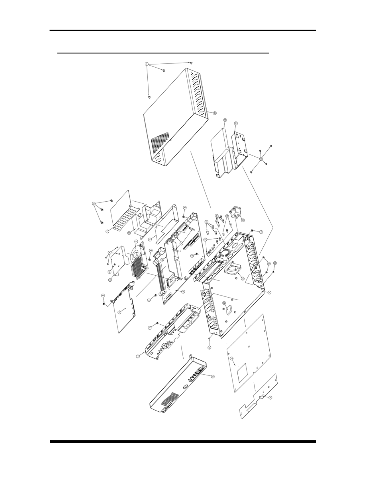
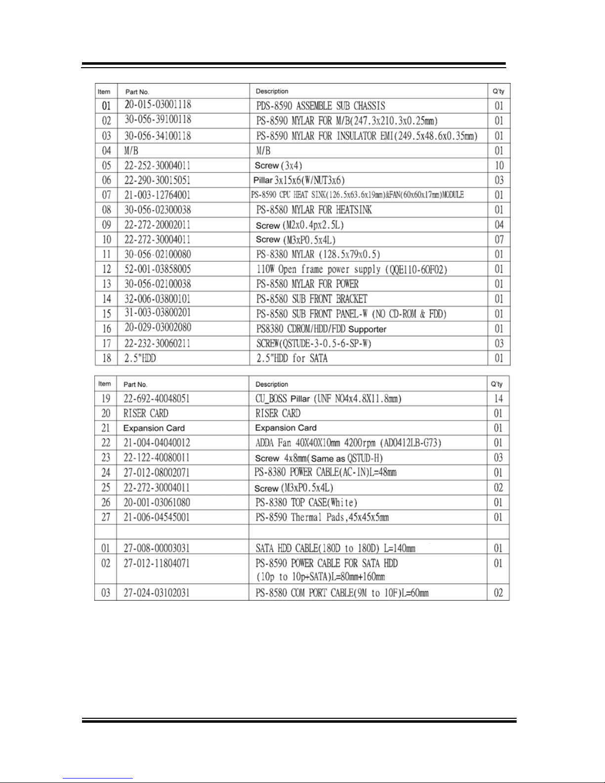
This appendix contain exploded diagram of the system.
Section includes:
z Exploded Diagram for Whole System Unit
APPENDIX
A
Page 73
Appendix A System Assembly
Page: A-2
BPC-8590 USER
′
S MANUAL
EXPLODED DIAGRAM FOR WHOLE SYSTEM UNIT
Page 74
Appendix A System Assembly
BPC-8590 USER′S MANUAL
Page: A-3
Page 75

Page: B-1
TECHNICAL
SUMMARY
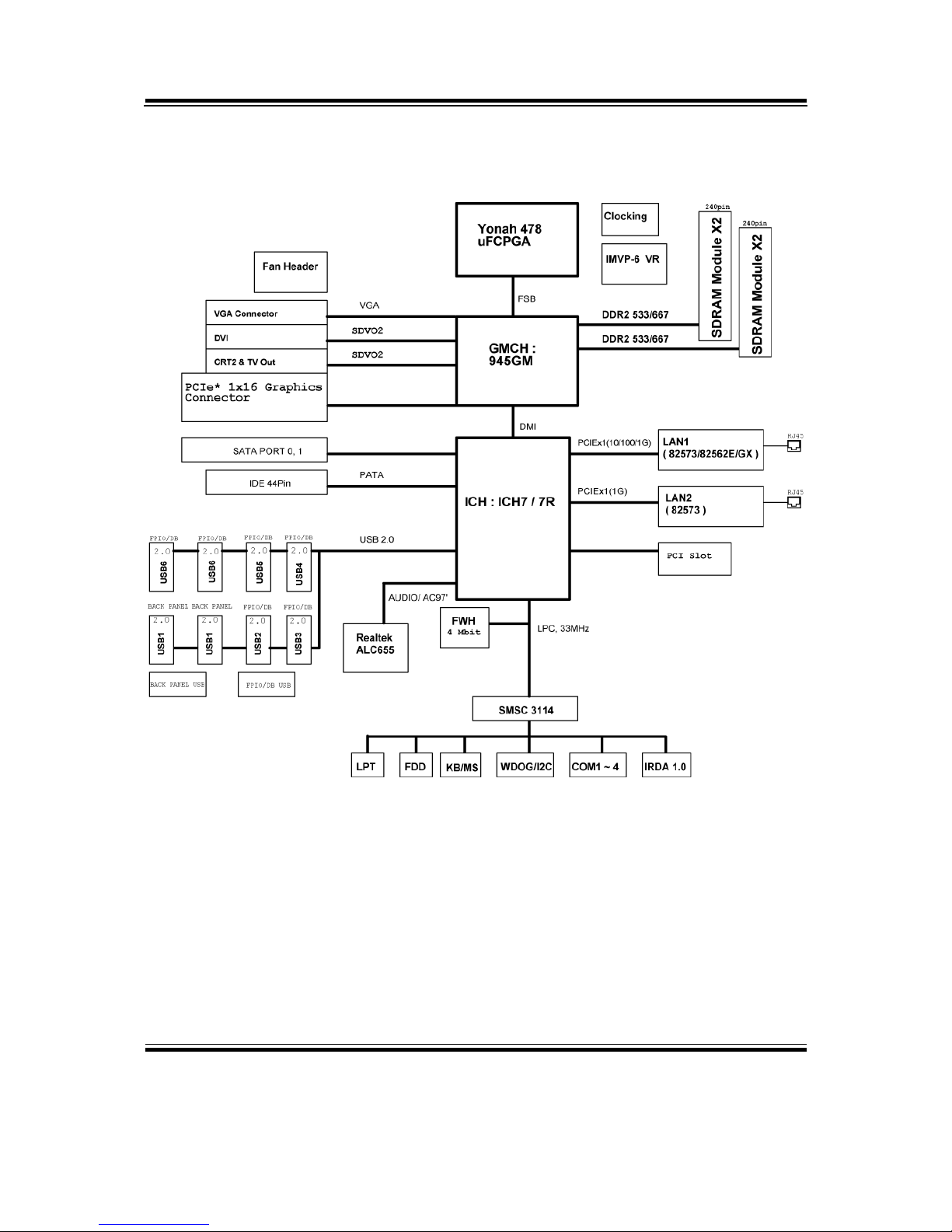
This section introduce you the maps concisely.
Section includes:
z Block Diagram
z Interrupt Map
z RTC (Standard) RAM Bank
z Timer & DMA Channels Map
z I / O & Memory Map
APPENDIX
B
Page 76
Appendix B Technical Summary
Page: B-2
BPC-8590USER
′
S MANUAL
BLOCK DIAGRAM
Page 77

Appendix B Technical Summary
BPC-8590 USER′S MANUAL
Page: B-3
INTERRUPT MAP
IRQ ASSIGNMENT
0 System TIMER interrupt from TIMER-0
1 Keyboard output buffer full
2 Cascade for IRQ 8-15
3 Serial port 2
4 Serial port 1
5 Parallel Port 2
6 Floppy Disk adapter
7 Parallel port 1
8 RTC clock
9 Available
10 Serial 3
11 Serial 4
12 PS/2 Mouse
13 Math coprocessor
14 IDE Controller
15 IDE Controller
Page 78

Appendix B Technical Summary
Page: B-4
BPC-8590USER
′
S MANUAL
RTC (STANDARD) RAM BANK
CODE ASSIGNMENT
00h Seconds
01h Second alarm
02h Minutes
03h Minutes alarm
04h Hours
05h Hours alarm
06h Day of week
07h Day of month
08h Month
09h Year
0Ah Status register A
0Bh Status register B
0Ch Status register C
0Dh Status register D
0Eh-7Fh 114 Bytes of User RAM
Page 79

Appendix B Technical Summary
BPC-8590 USER′S MANUAL
Page: B-5
TIMER & DMA CHANNELS MAP
Timer Channel Map
:
Timer Channel Assignment
0 System timer interrupt
1 DRAM Refresh request
2 Speaker tone generator
DMA Channel Map
:
DMA Channel Assignment
0 Available
1 Available / Parallel
2 Floppy Disk adapter
3 Available / Parallel
4 Cascade for DMA controller 1
5 Available
6 Available
7 Available
Page 80

Appendix B Technical Summary
Page: B-6
BPC-8590USER
′
S MANUAL
I/O & MEMORY MAP
Fixed I/O Ranges Decoded by ICH2
:
I/O Address Read Target Write Target Internal Unit
00h-08h DMA Controller DMA Controller DMA
09h-0Eh Reserved DMA Controller DMA
0Fh DMA Controller DMA Controller DMA
10h-18h DMA Controller DMA Controller DMA
19h-1Eh Reserved DMA Controller DMA
1Fh DMA Controller DMA Controller DMA
20h-21h Interrupt Controller Interrupt Controller Interrupt
24h-25h Interrupt Controller Interrupt Controller Interrupt
28h-29h Interrupt Controller Interrupt Controller Interrupt
2Ch-2Dh Interrupt Controller Interrupt Controller Interrupt
2Eh-2Fh LPC SIO LPC SIO Forwarder to LPC
30h-31h Interrupt Controller Interrupt Controller Interrupt
34h-35h Interrupt Controller Interrupt Controller Interrupt
38h-39h Interrupt Controller Interrupt Controller Interrupt
3Ch-3Dh Interrupt Controller Interrupt Controller Interrupt
40h-42h Timer/Counter Timer/Counter PIT (8254)
43h Reserved Timer/Counter PIT
4E-4F LPC SIO LPC SIO Forwarder to LPC
50h-52h Timer/Counter Timer/Counter PIT
53h Reserved Timer/Counter PIT
60h Microcontroller Microcontroller Forwarder to LPC
61h NMI Controller NMI Controller Processor I/F
62h Microcontroller Microcontroller Forwarder to LPC
63h NMI Controller NMI Controller Processor I/F
64h Microcontroller Microcontroller Forwarder to LPC
65h NMI Controller NMI Controller Processor I/F
66h Microcontroller Microcontroller Forwarder to LPC
67h NMI Controller NMI Controller Processor I/F
70h Reserved5 NMI & RTC controller RTC
71h RTC Controller RTC Controller RTC
72h RTC Controller NMI & RTC controller RTC
73h RTC Controller RTC Controller RTC
74h RTC Controller NMI & RTC controller RTC
75h RTC Controller RTC Controller RTC
76h RTC Controller NMI & RTC controller RTC
77h RTC Controller RTC Controller RTC
Page 81

Appendix B Technical Summary
BPC-8590 USER′S MANUAL
Page: B-7
I/O Address Read Target Write Target Internal Unit
80h DMA Controller DMA controller &
LPC/PCI
DMA
81h-83h DMA Controller DMA Controller DMA
84h-86h DMA Controller DMA Controller &
LPC or PCI
DMA
87h DMA Controller DMA Controller DMA
88h DMA Controller DMA Controller &
LPC or PCI
DMA
89h-8Bh DMA Controller DMA Controller DMA
8Ch-8Eh DMA Controller DMA Controller &
LPC or PCI
DMA
08Fh DMA Controller DMA Controller DMA
90h-91h DMA Controller DMA Controller DMA
92h Reset Generator Reset Generator Processor I/F
93h-9Fh DMA Controller DMA Controller DMA
A0h-A1h Interrupt Controller Interrupt Controller Interrupt
A4h-A5h Interrupt Controller Interrupt Controller Interrupt
A8h-A9h Interrupt Controller Interrupt Controller Interrupt
ACh-ADh Interrupt Controller Interrupt Controller Interrupt
B0h-B1h Interrupt Controller Interrupt Controller Interrupt
B2h-B3h Power Management Power Management Power Management
B4h-B5h Interrupt Controller Interrupt Controller Interrupt
B8h-B9h Interrupt Controller Interrupt Controller Interrupt
BCh-BDh Interrupt Controller Interrupt Controller Interrupt
C0h-D1h DMA Controller DMA Controller DMA
D2h-DDh Reserved DMA Controller DMA
DEh-DFh DMA Controller DMA Controller DMA
F0h See Note 3 FERR# /IGNNE#/
Interrupt Controller
Processor interface
170h-177h IDE Controller1 IDE Controller1 Forwarded to IDE
1F0h-1F7h IDE Controller2 IDE Controller2 Forwarded to IDE
376h IDE Controller1 IDE Controller1 Forwarded to IDE
3F6h IDE Controller2 IDE Controller2 Forwarded to IDE
4D0h-4D1h Interrupt Controller Interrupt Controller Interrupt
CF9h Reset Generator Reset Generator Processor interface
Notes:
1. Only if IDE Standard I/O space is enabled for Primary Drive. Otherwise, the target is PCI.
2. Only if IDE Standard I/O space is enabled for Secondary Drive. Otherwise, the target is PCI.
3. If POS_DEC_EN bit is enabled, reads from F0h will not be decoded by the ICH2. If
POS_DEC_EN is not enabled, reads from F0h will forward to LPC.
 Loading...