

Page 1
CONTENTS
FEATURES
SPECIFICATIONS
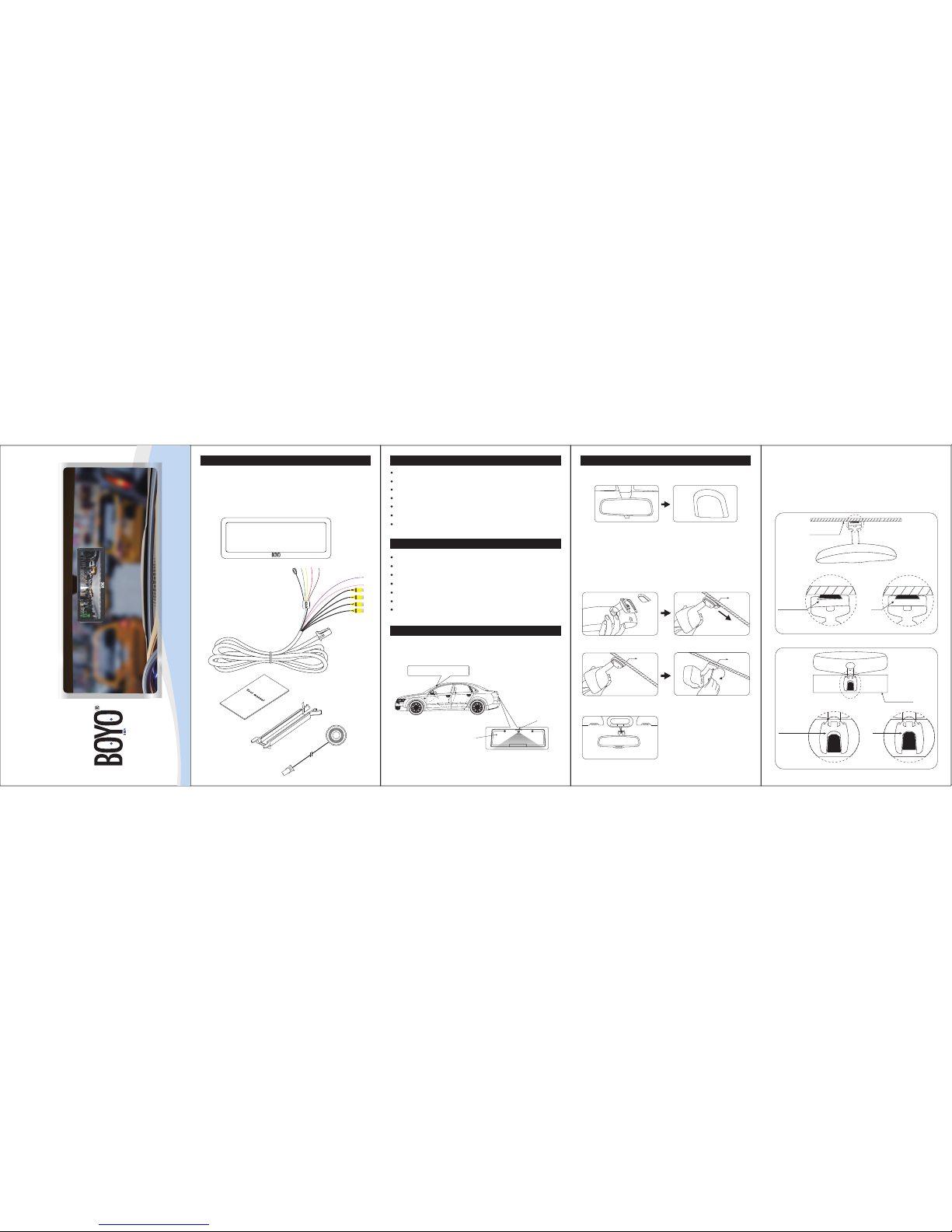
The package contains the following:
01 Rearview mirror monitor
02 Wire harness
03 User manual
04 Wire cover
05 Wire control
Screen size: 7.3 inch
Aspect resolution: 1280(H)*390(V)
Working voltage: 12V
OO
Working temperature: -4 F~+149 F
Signal system: PAL/Auto/NSTC
Brightness: about 1100cd/m2
Display screen: TFT-LCD
02
01
04
03
7.3 inch wide LCD display screen
Frameless design
4-way video inputs
Back-up camera display
Adjustable Back up guide lines
Automatic brightness adjustment
Channel switch among front, back, left, right
◆
VTM73FL
7.3 Inch Frameless Rear View Mirror Monitor with Full
Display Screen
05
HOW TO INSTALL MIRROR MONITOR
Remove the original mirror
CAUTION!
Car factory original mirror The plate on the windshield
Different cars have different brackets. It depends on your vehicle maker and
manufacturer.There are many methods to remove the original rear view
mirror, however, please don’t force the mirror off the bracket.
The manufacturer will not be responsible for damage caused to your car by
wrong installation of the mirror.
NOTE: Always use caution, DO NOT force the mount. We will not be
responsible for broken windshields. If you are not sure how to remove
or re-install the mirror seek trained, qualied help.
Install mirror monitor on the plate
Install rear view mirror along this directionTake down your original mirror, and make
the mirror monitor ready
windshield
Please make sure to install the mirror
to the end of the bottom without any loose
Contrarotate the xed rear view mirror
Torque is about 0.8-1.3 N.m
5
Dangerous
OK
Windshield
Windshield
Dangerous
OK
1.
2.
windshield
windshield
HOW TO INSTALL REVERSE CAMERA
When a camera needs to be installed at the rear of vehicle, a good position
is usually at the top of the License plate where there is an under ledge.
1BAM 2XX
AM
2
X
License plate
Camera
Rear view mirror monitor
Page 2
FRONT BUTTONS OPERATION HOW TO WIRE MENU SETTING
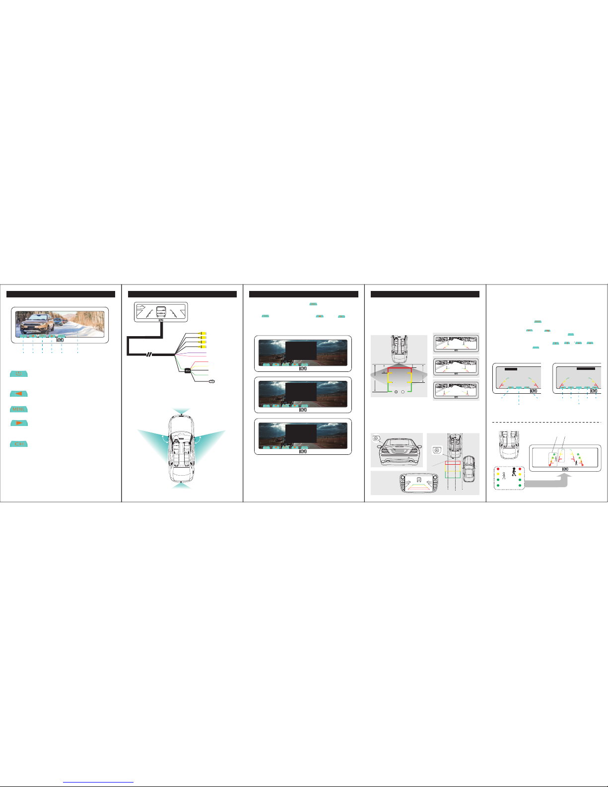
Non-trigger state: turn on/off screen
Trigger state: unusable
Non-trigger state: channel switch
Trigger state: unusable
In Video, Camera state: brightness down
In Video, Camera state: brightness down
In Video, Camera state: brightness up
12345 6
In Video, Camera state, short press “ ”, you can switch among
“PICTURE”, “SYSTEM”,“SETTING” or enter out. When you enter “PICTURE”,
press “ ” to switch among the items.“ ” and “ ” are to
change the gure of each setting. “SYSTEM”, “SETTING” is the same as
explains above.
Black to GND
Red to ignition +12V
to left camera
to right camera
to front camera
to back up camera
trigger line 1
trigger line 2
Yellow to battery
Green to back car singal
Wire control
The advisable installation position for camera
Back up camera
Front camera
Left camera
100
0
Right camera
100
0
11 ADJUSTABLE GUIDE LINE
About guide line
What the regular guide line is
About “WIRE CTR DELAY”
3m
1m
2m
0.4m
3m
2m
1m
MXT.71D
Generally, to help drivers estimate the distance from obstacles, there are
three lines for reference -red, yellow and green.Those lines are displayed on
the monitor when reversing. The green line is 3m away from the back of car
and the yellow line is 2m. The distant red line is1m away from the backside
of car while the closed red line is 0.4m. Both reference lines on the left and
right should leave 0.2m from the car.
Regular guide line is xed. But installation sites of cameras are different as
well as car size. The xed guide line is not accurate enough for drivers.
There is a great difference among regular and xed guide lines and car's real
guide lines, especially when camera is mounted on the left or right side of
car backside.
This function is used with wire control switch.
1. If "WIRE CTR DELAY" is setted "OFF", this function is same as the touch
buton "CH" .
2.If "WIRE CTR DELAY'' is stted as other parameters, you switch one video
screen to another one by wire control switch, once the delay time is up,
the screen will be automatically back to the pre-switching video screen.
How to adjust the guide line
R
Display on the monitor
L
Clockwise
Rightleft
up downanticlockwise
Short press: switch to next item
Long press: save the setting and exit
Short press: switch to next item
Long press: save the setting and exit
Right position
Wrong position
According to the site of standard reference line, we can put references such
as desks in the back side of the car. Compared with the marked references,
we can adjust the sites and angles of two guide lines displayed on the
monitor. You will get the accurate and safety guide lines once it coincides
with the references.
Reversing state: Long press“ ” to enter “guide line adjustment” mode.
The system is defaulted to adjust left guide line rst.
Now you can use the " " and " " keys to rotate the left guide line
counterclockwise and clockwise; short press the " " key to switch to
the next item, at this moment, you can adjust the left guide line among up,
down, left and right by pressing buttons " ", " ", " ", " " .
Continue to short press the " " button, switch to adjust the right guideline
line. The method is same as above.
Guide
Line Sel
Angle-R: 27 H-R: 95 V-R: 210
Angle-L: 25 H-L: 91 V-L: 210
Guide
Line Sel
Angle-L: 25 H-L: 91 V-L: 210
Angle-R: 27 H-R: 95 V-R: 210
Guide
Line Sel
Guide
Line Sel
PICTURE
BRIGHTNESS 50
50
50
CONTRAST
COLOR
SYSTEM
SCALE ON
ENGLISH
OFF
LANGUAGE
PRESET
SETTING
FRONT DELAY 00
OFFWIRE CTR DELAY
 Loading...