

Page 1
6
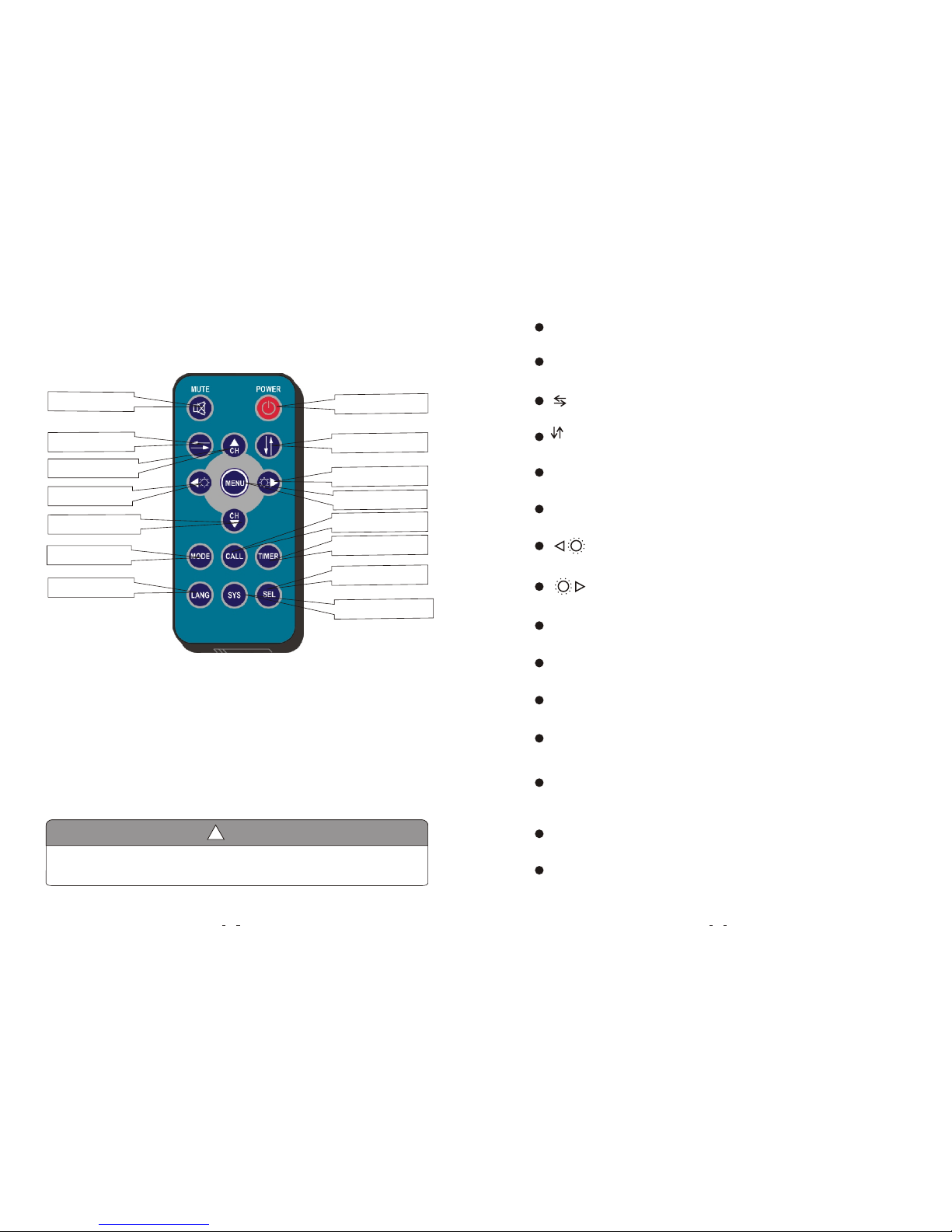
6. Remote Control Operation
Power Switch
Menu
Call
Timer
Select AV1/AV2/AV3
AUTO / PAL / NTSC
Vertical Flip
Channel Selection Up
Less Brightness
Picture Mode
Language Selection
Horizontal Flip
1. Please align the remote control with the infrared-receiving window on the monitor to operate.
2. Never disassemble the remote control or allow it to drop, or become wet.
3. Press the control buttons firmly. Allow 2 seconds for the picture to change.
!
Notice
Channel Selection Down
More Brightness
7
MUTE (Mute):
Press to select ENABLE/MUTE sound.
CH+ (Channel Selection+):
Press to select channel/item on menu.
Press to turn picture horizontally.
(Horizontal Turning of Picture):
MENU :
Press to show menu.
CH- (Channel Selection-):
Press to select channel/item on menu.
CALL (Call):
Press to display current channel.
MODE (Picture Mode):
Press to select different picture modes (PERSONAL / STANDARD / SOFT / VIVID / LIGHT).
POWER (Power Switch):
Press to turn on/off the monitor.
Press to turn picture vertically.
(Vertical Turning of Picture):
TIMER:
Press to set the timer to shut down the monitor(0, 10, 20, 30, 40, 50, 60, 70, 80, max 90 minutes).
SEL:
Press to select AV channels.
LANG(Language Selection):
Press to select language display of ENGLISH, FRENCH, GERMAN options.
Press to decrease Brightness.
Press to increase Brightness.
SYS:
Press to select AUTO / PAL / NTSC.
Mute
Page 2
8
7. Basic Operation
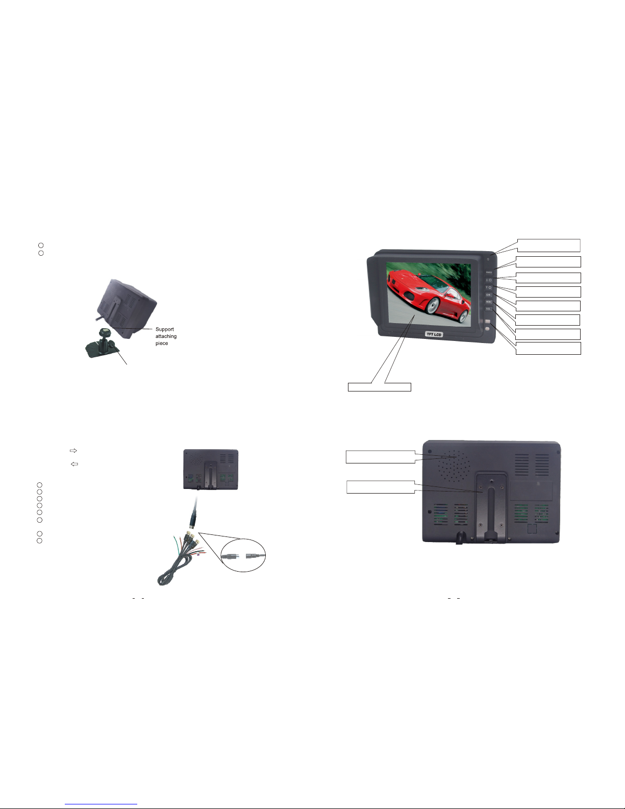
2. Connection of AV Conversion Cable
5
Brightness increase
Brightness decrease
AV1/AV2/AV3 Selector
Menu
Power indicator
5. Parts Identification
Hol d the cab le , alig n the sid e of jack
mar ked wit h on fema le 13-p in
con necto r with th e male 13 -pin co nnect or
mar ked wit h then pl ug in.
Black 4 pin male for Camera1.
Black 4 pin male for Camera2.
Black 4 pin male for Camera3.
Single red wire for power supply of DC / 12-32V.
Single black wire for GND.
Single brown wire to positive power wire of the
back-up light.
Single white wire to positive power wire of left Light .
Single blue wire to positive power wire of right light .
11
22
33
44
55
66
77
88
Channel selection -
Remote control sensor
Power switch
Digital Color LCD screen
1.Installation of Base Support:
Loudspeaker
Mounting bracket installation
Knob
Adjust the angle of the monitor and tighten the knob on the center mounting bracket.
Adjust monitor level by sliding the support to the desired height.
11
22
Page 3
4
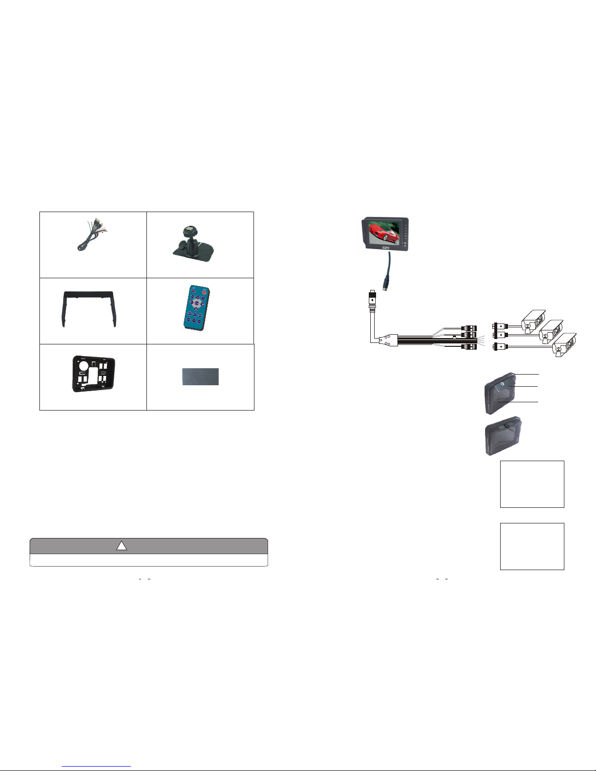
4. Accessories
Accessory supply may be different for different application.
!
Special Notice
9
Blue
ro
nB
w
White
Black 4
pin ma
le
B
k
in
lac
4 p
male
k in
Blac
4
p
male
Black
Red
Black 13 pin female
Black 13 pin male
Insert the detaching piece as indicated by the white
arrow. Press in and lift up, the monitor will be released
from the flush mount.
4. Removing the Monitor:
1.
2.
Remove the monitor.
Black 4 pin male for Camera 1 / Camera 2 / Camera 3.
Single red wire for positive power supply of DC / 12-32V.
Single black wire for GND.
Single brown wire to positive power wire of back-up light .
Single white wire to positive power wire of left turn light .
Single blue wire to positive power wire of right turn light .
2. When the blue wire is connected to the positive wire of the right turn
light, the monitor automatically switches to CAM 2 (right side
camera) when the right turn indicator is activated.
1. When the white wire is connected to the positive wire of the left turn
light , the monitor automatically switches to CAM1 (left side
camera) when the left turn indicator is activated.
Center mount bracket
AV and power supply
adapter cable
IR Remote control
Flush mount
Sun shield
Color LCD screen
Flush mount
Detaching piece
5. Reversing Display:
Detaching Piece
Av1
Av2
Page 4
10
2. Features
3. Technical Specifications
1. TFT LCD monitor with wide angle view and high resolution display.
2. Picture image may be adjusted for Horizontal, Vertical, Mirror and Normal viewing.
3. Select from 3 languages for user operation.
4. Automatic backlighting for buttons.
5. Full-function remote control.
6. Multiple video formats available: AUTO/ PAL / NTSC.
7. Up to 3 AV inputs.
8. Operates from 12 - 32V. Supports 12V or 24V automobile battery.
9. Automatically switches to back-up, left or right side camera views.
10. On-board speaker.
11. OSD keeps normal image even if it is mirror image in horizontal.
3
!
Special Notice
All specifications are subject to change without notice.
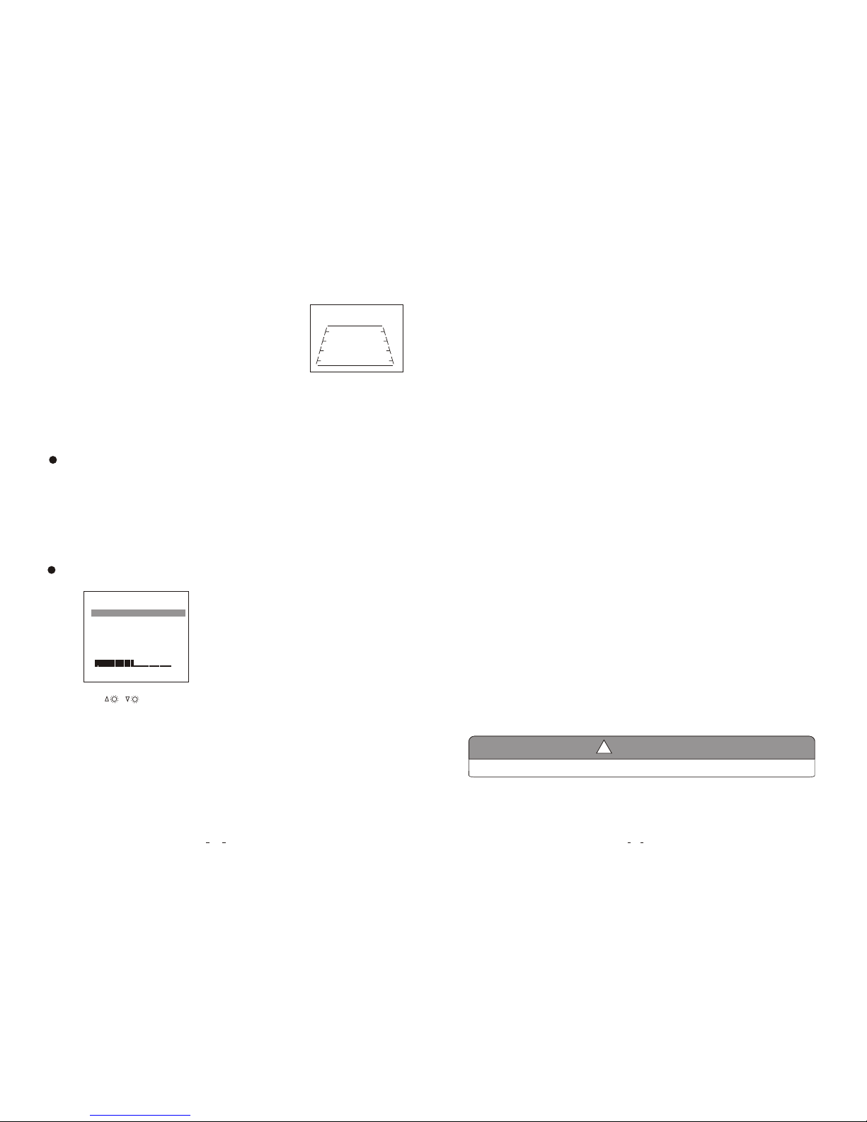
8. Menu
Press MENU to display the following options and settings:
1. PICTURE
2. OPTION
3. SYSTEM
(1) Picture
The BRIGHT,CONTRAST, COLOR, VOLUME options
will display on the screen as illustrated below:
Press CH- to select BRIGHT.
Press / to adjust the BRIGHT Level.
PICTURE
BRIGHT
CONTRAST
COLOR
VOLUME
50
50
50
50
50
3. When the brown wire is connected to the positive wire of back-up light,
the monitor automatically switches to CAM 3 (back-up camera) when
the back-up light is turned on. The distancing grid will also be displayed.
1. Product: 5" Digital TFT- LCD Color monitor.
2. Audio output: 1W.
3. Loudspeaker: one 4.0cm round loudspeaker.
4. Power supply: Automobile storage battery (12-32V).
5. Power consumption: < 7 W .
6. Outer dimension: 147.6mm (W) × 109mm (H) × 26.5mm (T) (without flush mount),
165mm (W) × 126mm (H) × 29.2mm (T) (with flush mount).
7. Dot pitch: 0.0529(H) × 0.1587 (V).
8. Resolution: 640 x 3(RGB) x 480 .
9.Color depth:24 bit
10.Display colors:16.7M dithering.
11.Contrast: 500:1.
2
12.Brightness: 200cd/m .
13.Viewing angle: U: 50 / D: 70, R/L: 70.
14.Operating temperature: -20~+70ºC,RH90%.
15.Storage temperature: -30~+80ºC,RH90%.
Page 5
2
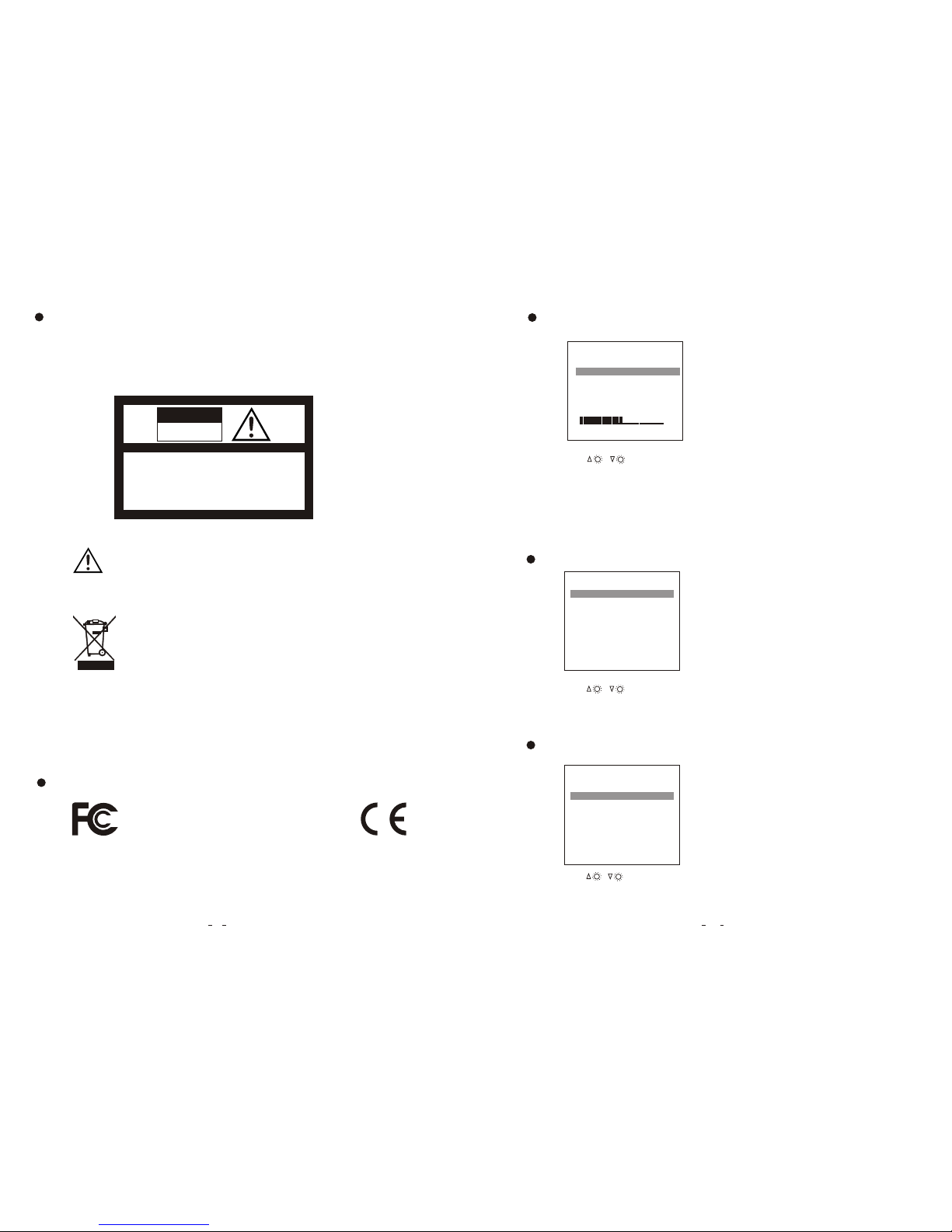
1. Remove all the cable connections from the monitor before cleaning the unit.
2. Use a mild household detergent and clean the unit with a slightly damp,soft cloth.
Never use strong solvents such as thinner or benzine, as they might damage the finish
of the device.
CAUTI ON
RISK OF E LECTR IC SHOC K
DO NOT OP EN
CAUTI ON: TO RE DUCE TH E RISK OF E LECTR IC SHOC K,
DO NOT RE MOVE CO VER (OR B ACK).
NO USER -SERV ICEAB LE PART S INSID E.
REFER S ERVIC ING TO QU ALIFI ED SERV ICE PER SONNE L.
This symbol is intended to alert the user to the presence of important operating and
maintenance (servicing) instructions in the literature accompanying the appliance.
You are cautioned that any changes or modifications not expressly approved in this manual could
void your warrantee and neccessitate expensive repairs.
CAUTION
This symbol is intended to alert the user not to waste electrical and electronic
equipment.
Declaration of conformity
This device complies with Part 15 of the FCC Rules. Operation is
subject to the following two conditions:
(1) This device may not cause harmful interference.
(2) This device must accept any received, including
nterference that may cause undesired operation.
interference
i
E13
Maintenance
11
Press CH- to select CONTRAST.
Press / to adjust the CONTRAST level.
PICTURE
BRIGHT
CONTRAST
COLOR
VOLUME
50
50
50
50
50
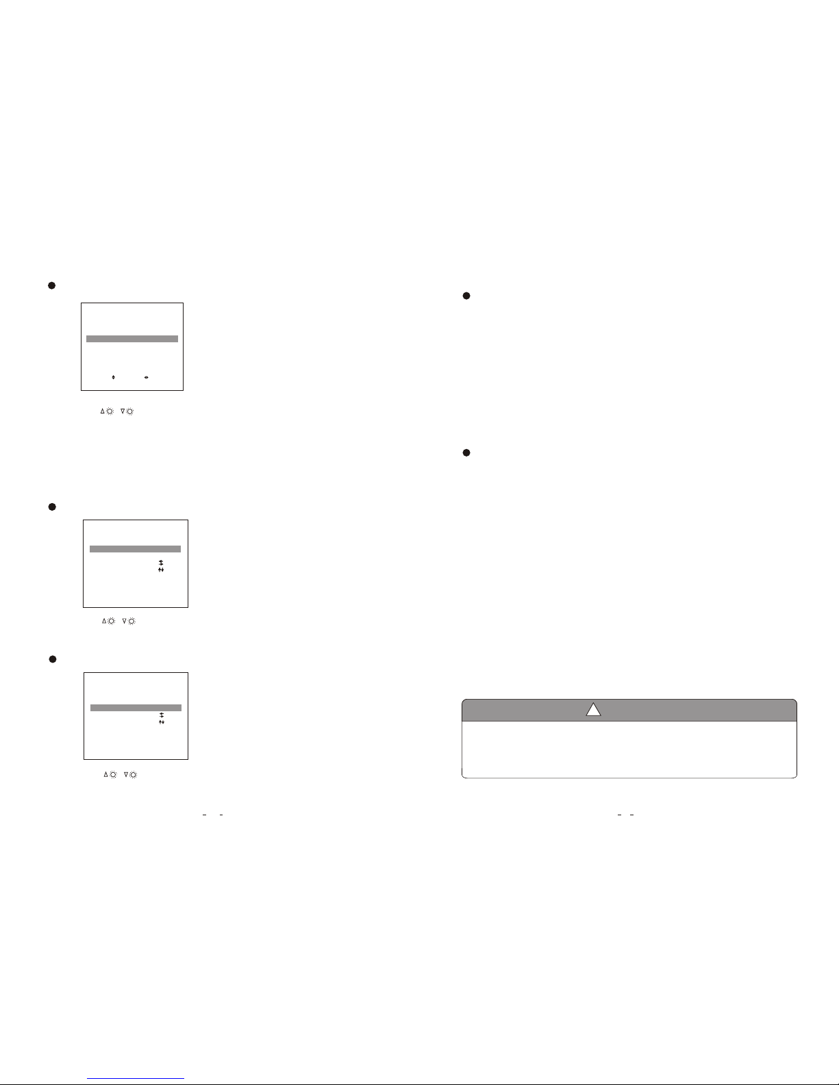
(2) Option
The LANG ,SCALE ,CAM 1 ,CAM 2 ,CAM 3 options display on the screen as illustrated below :
Press CH- to select LANG.
OPTION
SCALE
CAM1
CAM2
CAM3
ON
NORMAL
NORMAL
NORMAL
LANG
ENGLISH
Press / to select ENGLISH / FRENCH / GERMAN.
.
OPTION
SCALE
CAM1
CAM2
CAM3
ON
NORMAL
NORMAL
NORMALL
LANG
ENGLISH
Press / to select ON/OFF.Scale refers to the reversing distance
indicator displayed on the monitor.
Press CH- to select SCALE.
Page 6
12
1. Precautions
Storage and Keeping
1. Do not expose the monitor to excessive heat or cold. The storage temperature of this device
is -30~+80℃, and the operating temperature is -20~+70 ℃. The humidity is Rh90%.
2. Never use this device near a bathtub, wash basin, kitchen, damp basement, swimming pool or
similar places.
3. Never use this device in environments with excessive moisture, dust or smoke.
4. Avoid dropping or striking this device.
5. Avoid using this device in enclosed spaces, areas with excessive vibration or subject to
severe impacts.
6. Never puncture, scratch or use abrasive cleaning materials on this device..
7. Do not place cables where they may be pinched or stepped on.
8. Leave at least a 2" space between the monitor and walls, cabinets or other objects to allow
adequate air circulation around the unit.
9. The monitor is not designed to be waterproof.
1
Operating Precautions
1. The device may be powered by a 12 or 24 volt automotive battery or vehicle electrical system
2. Observe polarity.
power s do not
Make sure all cables are connected properly. Improper cable connections may
damage the monitor. Remove the cable connection when you intend to use the unit.
Occasionally, a few highlights or dark spots may occur on the LCD screen. This is a very common
phenomenon in active matrix display technology, and doesn’t necessarily indicate any defects or faults.
Never try to repair this device by yourself. In case of any problems, please turn off the display at once and
notify our company or authorized dealer. The monitor is a complex device. Any disassembly or modification
may lead to damage and void the warrantee.
!
Special Notice
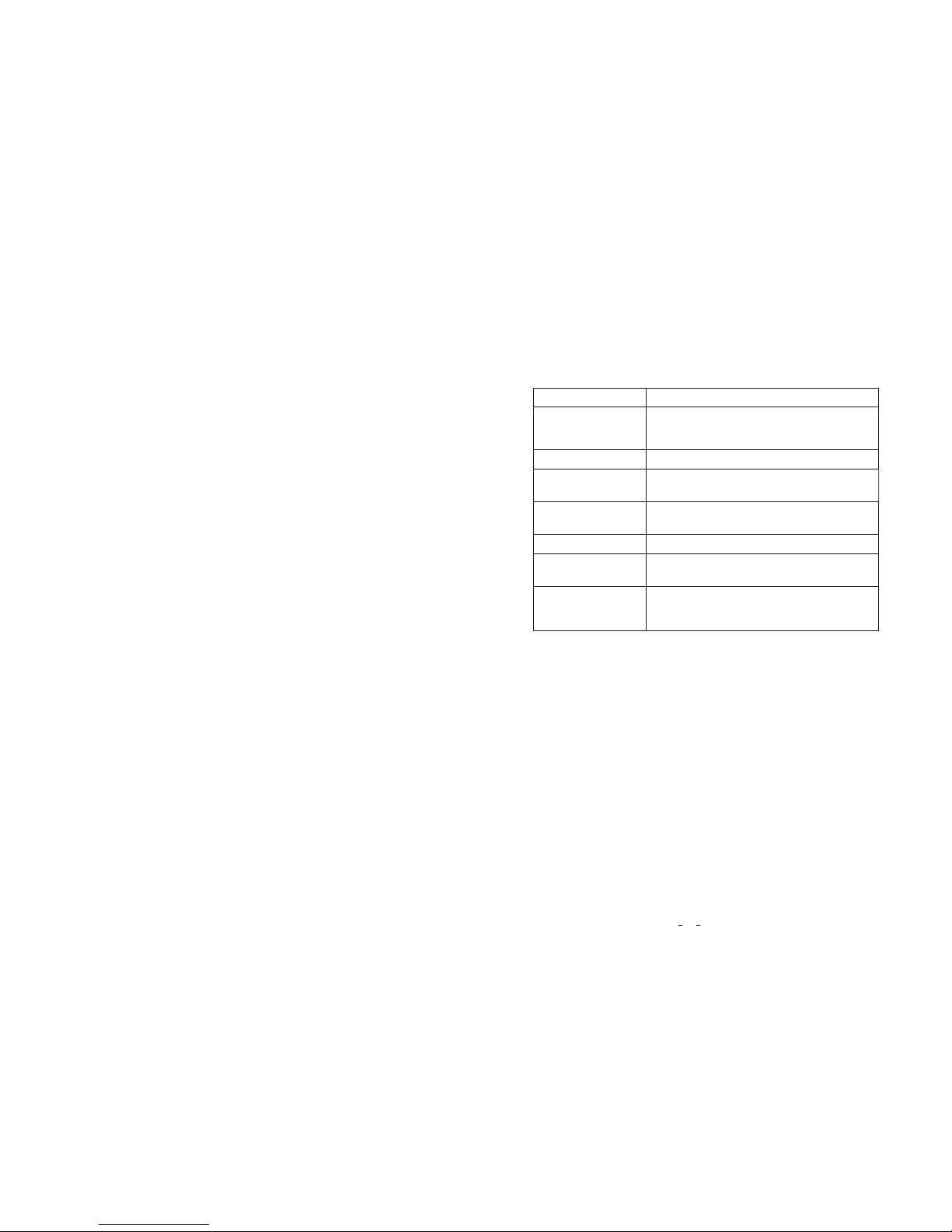
(3) System
The COLOR-SYS, BLUE BACK, HORIZONTAL, VERTICAL functions will display on
the screen as illustrated below :
OPTION
SCALE
CAM1
CAM2
CAM3
ON
NORMAL
NORMAL
NORMAL
LANG
ENG
Press / to select NORMAL / MIRROR.
.
SELECT
ADJUST
Press CH- to select CAM1.
Press / to select AUTO / PAL / NTSC.
.
SYSTEM
BLUE BACK
HORIZONTAL
VERTICAL
COLOR -SYS
AUTO
ON
Press CH- to select BLUE BACK.
Press / to select ON / OFF.
.
SYSTEM
BLUE BACK
HORIZONTAL
VERTICAL
COLOR -SYS
Press CH- to select COLOR-SYS .
SYSTEM
BLUE BACK
HORIZONTAL
VERTICAL
COLOR -SYS
AUTO
ON
Page 7
13
Symptom Possible Causes/Solutions
No picture, no sound
No picture
No sound
Dark picture
No color
Upside down or lateral
inverted picture
No reversing function
(i.e. Picture)
Improper connection of automobile adapter. Use of unauthorized power supply. Power switch is on OFF position.
Check whether AV cable is properly connected.
Check whether audio wire is properly connected or the sound
volume is turned off or set too low.
Check whether brightness and contrast are adjusted correctly;
Check whether the environments temperature is too low.
Adjust the color settings.
The black wire of the monitor AV cable to the reversing light may
be loose. The red wire from the monitor may be loose.
9. Troubleshooting
The Symptoms described below do not necessarily mean a failure within the display.
Please check the following items before you initiate request for repair.
Use the remote control horizontal /vertical selection switch to set
proper orientation
Page 8

1. Precautions
2. Features
4. Accessories
5. Parts Identification
6. Remote Control Operation
7. Basic Operation
8. Menu
(1) Picture
(2) Option
(3) System
9. Troubleshooting
Contents
13
3. Technical Specifications
12
11
10
8
6
5
10
…………………………………………………………
…………………………………………………………
…………………………………………………………
………………………………………………………
………………………………………………………
………………………………………
………………………………………………
……………… ………………………………………
……………………………………………
……………………………………………………
…………………………………………………………
……………………………………………………
4
3
3
1
Page 9

Page 10
VTM5000
 Loading...