

Page 1

Mini Handheld Pulse Oximeter
User’s Manual
Page 2

Mini Handheld Pulse Oximeter
Disclaimer Statement
The company does not in any form guarantee the errors in this manual, installation errors and operator
errors, and does not assume any legal liability for incidental or consequential damages.
The contents contained in this manual are protected by the copyright law. All rights are reserved, and
without prior written permission of the company, any part of this manual can not be reproduced,
photographed, copied, or translated into other languages.
The company only considers to be responsible for the reliability, security and performance of the
instrument under the following circumstances, namely assembly operation, expansion, readjustment,
performance improvement and repair, all of which are performed by the personnel or institutions
authorized by the company; relevant electrical devices are in line with national standards; the instrument
is operated in accordance with the guidance in this manual.
The contents of this manual may be changed without notice.
Before using the product, please read the contents of this manual carefully for proper use of the product.
Please keep this manual after reading it, so as to access at any time when needed.
Foreword
This manual describes in detail the purpose, function and operational use of the product. Before using
this product, please carefully read and understand the contents of this manual to ensure proper use of
this product can be, and to ensure that the patient and operator safety.
The manual introduces this product according to the most complete configuration, so some contents
may not apply to your purchased product. If you have any questions, please contact with the company.
Please place this manual near the product, so as to be able to convenient and timely access when
needed.
Applicable objects
This instrument is suitable for home users or professional clinical staffs, and users shall read the manual
carefully before using this instrument.
Illustrations
All illustrations in this manual are provided only for reference, and settings or data in the illustrations may
not be entirely consistent with the actual display you see on the product.
Warranty and maintenance services
Scope of Free Services:
Page 3

Mini Handheld Pulse Oximeter
Any device in compliance with the range of the company's warranty service can enjoy free services.
Scope of Paid Services:
(1) The company will implement the paid services for any device beyond the range of the company’s
warranty service;
(2) Even during the warranty period, the product needs to be repaired due to the following reasons:
human damage; grid voltage exceeding the specified range of device; irresistible natural disasters.
The company is irresponsible for the direct, indirect or final damage and delay caused by under the
following circumstances (including but not limited to):
Component disassembly, stretching and re-commissioning; replacement of accessories without
permission of the company or the machine repair by non-authorized personnel of the company.
Return of goods
Return process
The company is really necessary to be returned, follow these steps:
1. The acquired right of return. Contact our customer service department, informing of the product serial
number; if the serial number is non-legible, the return of goods will not be accepted. Please specify the
product model, serial number, and brief reason for return.
2. Freight: The device is shipped to the company for maintenance, and meanwhile users have to bear
the shipping cost (including customs fees).
Page 4

1
Contents
Chapter I Overview
....................................................................................................................................................
4
1.1 Safety Information
...............................................................................................................................................
4
1.1.1 Warning
..............................................................................................................................................
4
1.1.2 Caution
...............................................................................................................................................
5
1.1.3 Attention
.............................................................................................................................................
6
1.2 Symbol and Description
.....................................................................................................................................
7
Chapter II Product Overview
....................................................................................................................................
7
2.1 Introduction
...................................................................................................................................................
7
2.1.1 Intended use
.....................................................................................................................................
7
2.1.2 Environmental Requirements
........................................................................................................
7
2.1.3 Contraindications
.............................................................................................................................
9
2.2 Appearance
..................................................................................................................................................
9
2.2.1 Front View
.........................................................................................................................................
9
2.2.2 Rear view
.........................................................................................................................................
10
2.3 Screen Display
...........................................................................................................................................
11
2.3.1 SpO2 Parameter Area
...................................................................................................................
11
2.3.2 PR parameter area
........................................................................................................................
12
Chapter III Preparation before Use
.......................................................................................................................
13
3.1 Unpacking and Inspection
.......................................................................................................................
13
3.2 Power On
....................................................................................................................................................
13
3.3Shutdown
.....................................................................................................................................................
14
Chapter Ⅳ Menu Settings
......................................................................................................................................
14
4.1 Alarm
............................................................................................................................................................
14
4.1.1 SPO2 Alarm
....................................................................................................................................
1
3
4.1.2 Temp Alarm
.....................................................................................................................................
1
3
4.2Setup
............................................................................................................................................................
1
3
4.3System Setup
..............................................................................................................................................
16
4.3.1 Screen Brightness
.........................................................................................................................
1
5
4.3.2 Default Setup
...............................................................................................................................
19
4.3.3 Manufacturer Maintenance
..........................................................................................................
19
Chapter V Alarm
.......................................................................................................................................................
21
5.1 Alarm Type
..................................................................................................................................................
21
5.2 Alarm Status Icon
......................................................................................................................................
21
5.3 Alarm Pause
...............................................................................................................................................
22
5.4 Set Alarm Sound
........................................................................................................................................
22
5.5 Countermeasures to The Alarm
..............................................................................................................
22
Chapter Ⅵ SpO2
...................................................................................................................................................
23
6.1 Overview
..................................................................................................................................................
23
6.2 Safety Information
.....................................................................................................................................
24
6.3 Caring Stepsbin
.........................................................................................................................................
25
6.4 On/ Off Parameter Alarm
..........................................................................................................................
26
6.5 Set Alarm Limits
.........................................................................................................................................
26
Page 5

2
6.6 Measuring Influence Factors
...................................................................................................................
26
Chapter VII of temperature (TEMP) (optional)
....................................................................................................
27
7.1 Temperature Monitoring Operation Steps
.............................................................................................
27
7.2 Safety Information
.....................................................................................................................................
28
7.3 On / Off Parameters Alarm
......................................................................................................................
29
7.4 Set the Alarm Limit
....................................................................................................................................
29
7.5 Setting The Temperature Unit
.................................................................................................................
29
Chapter VIII Battery
.................................................................................................................................................
30
8.1 Overview
.....................................................................................................................................................
30
8.2 Installing The Batteries
.............................................................................................................................
30
8.3 Battery Recycling
.......................................................................................................................................
31
9.1 Inspection
....................................................................................................................................................
32
9.2 Cleaning
......................................................................................................................................................
33
9.3 Disinfection
.................................................................................................................................................
33
9.4 Scrap
...........................................................................................................................................................
34
Chapter Ⅹ Accessories
...........................................................................................................................................
35
A Product Specification
...........................................................................................................................................
36
B Default factory settings
........................................................................................................................................
40
C Alarm Information
.................................................................................................................................................
41
C.1 Physiological alarm information
.............................................................................................................
42
C.2 Technical alarm information
....................................................................................................................
42
D Manufacturer’s Declaration of the EUT
............................................................................................................
43
Page 6

3
Page 7

4
Chapter I Overview
1.1 Safety Information
Warning
Tip : potentially dangers or unsafe operations, and if they are not
avoided, it could result in death or serious personal injury or property
damage.
Caution
Tip : potentially dangers or unsafe operations, and if they are not
avoided, it could result in slight personal injury, product failure, damage
or property loss.
Attention
Highlight important considerations, and provide instructions or
explanations to make better use of this product.
This product is not involved in the information on danger level.
1.1.1 Warning
Warning
Users before using this Palm Pulse Oximeter should follow the
instructions set out in this manual; or else, any incorrect operation
Page 8

5
may result in serious injury. The company will assume no warranty
for improper use of this device.
The device is used in the medical field, and measurement results
serve only as reference.
Before use, users must check the device, cables and accessories to
ensure that they can properly work safely.
The device is not available in the presence of flammable gases or
other flammable anesthetic gases, in order to avoid explosion.
Do not open the housing of the oximeter, to avoid the risk of electric
shock. If necessary, please the company's staff maintain.
The oximeter is suitable for the occasions where an electrosurgical
device is used; where it shares with an electrosurgical device, the
user (doctor or nurse) should ensure the safety of the patient under
intensive care.
During defibrillation, do not touch patients; or else, it may cause
serious injury and death.
To prevent delays in treatment, make full alarm settings for each
patient, while alarm sound should also be able to be ensured when
alarming.
The physiological waveforms, physiological parameters and alarm
information and others displayed by the device are for doctor’s
reference, but can not be directly used as the basis for clinical
treatment.
Note to place the power line and all cables to avoid the hazard of
strangling patients or tripping other personnel.
To avoid personal injury, in addition to qualified technicians, other
persons can not repair the device.
1.1.2 Caution
Caution
To ensure patient safety, please use the accessories designated by
Page 9

6
the company.
When the product and accessories described in this manual are
about to exceed the period of use, they must be treated in
accordance with relevant product specifications. If you want to learn
more information, please contact the company or its representative
bodies.
Do not use a mobile phone near the oximeter, because the mobile
phone will generate too strong radiation field, which thus interferes
with the oximeter function.
Before the device is powered on, make sure that the voltage and
frequency of the power supply are in line with the requirements
specified on the device label or in this manual.
Please properly install or carry the device to prevent the device
falling or being damaged due to collision, receiving strong shock or
other mechanical force.
1.1.3 Attention
Attention
Mount the device at the place where it is easy to observe, operate and
maintain.
Place this manual near the device so as to be able to easily and
timely access when needed.
Before use, verify and correct and ensure that the device is working
properly.
If a liquid is spilled into the enclosure of the device, disconnect the
power supply immediately, and contact the maintenance personnel at
once.
The manual introduces the product according to the most complete
configuration, and the product you purchase may not have some of
Page 10
7
the configurations or functions.
Remove nail polish or artificial nails before oxygen probes are used.
Nail polish or artificial nails may cause inaccurate oximetry readings.
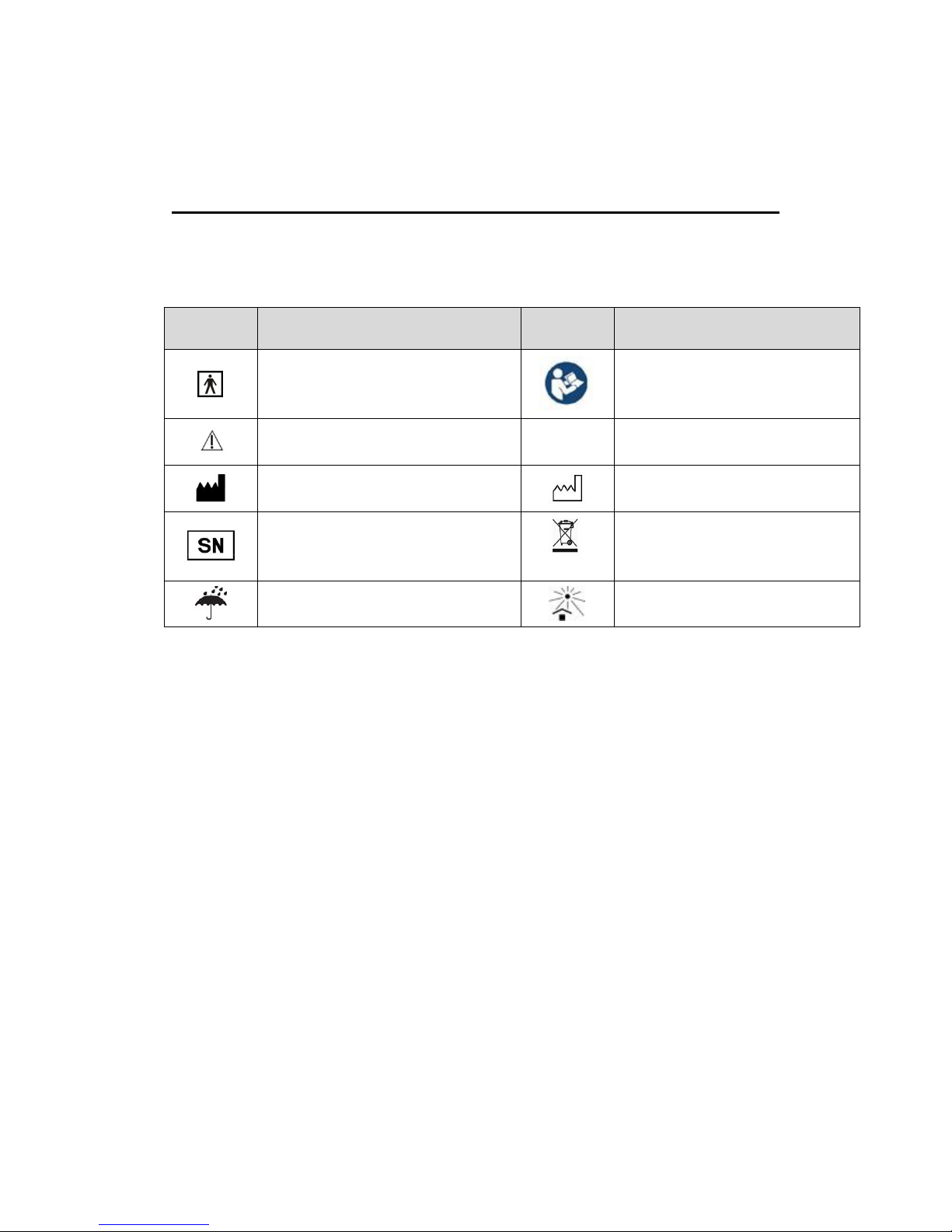
1.2 Symbol and Description
Symbol
Description
Symbol
Description
BF type applied part
Refer to operation manual
Cautions, please refer to attached
documents
IP22
Level of protecting against liquid
inlet
Manufacturer
Date of manufacture
Serial number
Recycled separately from other
household waste under the
WEEE directive
Keep dry
Keep away from sunlight
Chapter II Product Overview
2.1 Introduction
2.1.1 Intended use
The oximeter is suitable for both home care and hospital use to monitor patients’ vital sign
parameters, including blood oxygen saturation, pulse rate and body temperature (body
temperature is optional) .Palm Pulse Oximeter is a novel, compact and easy-to-carry
device. This device can be used in Emergency Room, home care and other occasions.
2.1.2 Environmental Requirements
Page 11

8
Temperature
Operating temperature 5(C)~40(C)
Transportation and storage temperature -20(C)~ 50(C)
Humidity
Operating humidity 15%~ 85%
Transportation and storage humidity ≤ 90 %
Atmospheric pressure
86.0kPa~106.0kPa;
Altitude
Working altitude -500 ~ 4,600m (-1,600 ~ 15,000
ft)
Transportation and storage altitude -500 ~ 13,100m (-1,600 ~
43,000 ft)
The operating environment of this device must comply with the requirements of the
environment specification in this manual.
When the device is moved from one scene to another one, due to differences temperature
or humidity, which may cause the device condensation. At this point, you must keep
waiting until the condensation condition disappears to use the device.
Warning
Please ensure that the device is operated under specified
environmental conditions; otherwise, it will not meet the technical
specification claimed in this manual, and may lead to unpredictable
consequences, which may bring damages to the device.
Attention
The oximeter can be used in hospitals, emergency room and
ambulance, as well as for home care.
Page 12
9
2.1.3 Contraindications
None
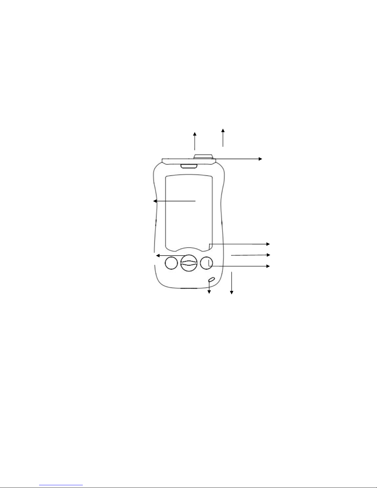
2.2 Appearance
2.2.1 Front View
1. Display screen
2.4-inch color LCD display screen
2. Power switch: In different situations, the key has different functions.
Start: After the battery is installed, short press the button to turn on the monitor.
Shutdown: in the startup state, long press the button for 2 seconds to turn off the
monitor.
3. Menu key
Press this key to enter the menu screen or select an option.
4. Alarm Indicator light
1
235
8
9
Page 13
10
Yellow and normally on
5. Up key
In different situations, the key has a different function. Press this key to move the
cursor upward, to increase the value of a menu option or to increase the pulse volume
and to complete other operations. The key also has an alarm pause function.
6. Down key
In different situations, the key has different functions. Press this key to move the cursor
upward, to reduce the value of a menu option or to decrease the pulse volume and to
complete other operations.
7. Micro USB interface
Connect the adapter
8. Oxygen sensor socket
connects with the oxygen saturation probes to achieve oxygen
detection.
9. Temperature sensor interface
Connected to the temperature probes to achieve temperature measurement.
10. Power indicator
Green: Connecting the AC power adapter, the oximeter being powered.
Off: the oximeter is not connected to AC
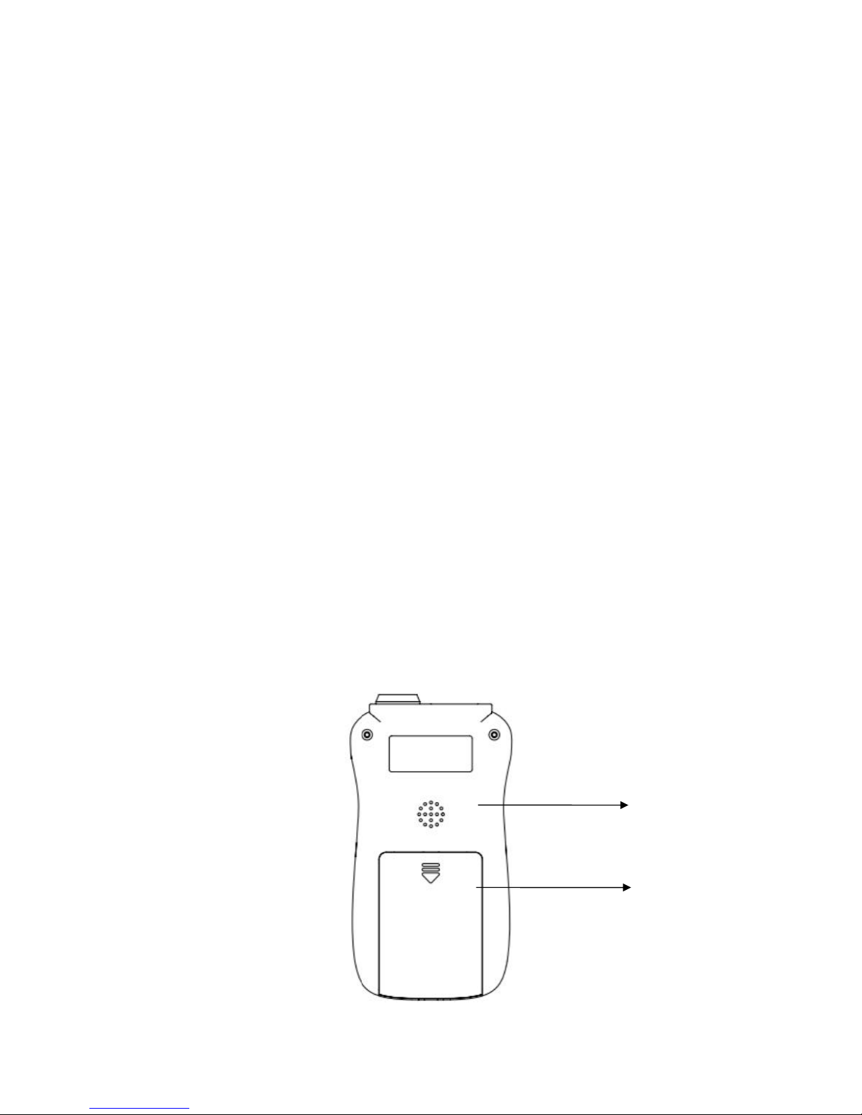
2.2.2 Rear view
1
2
Page 14
11
1. Speaker
2. Battery cover
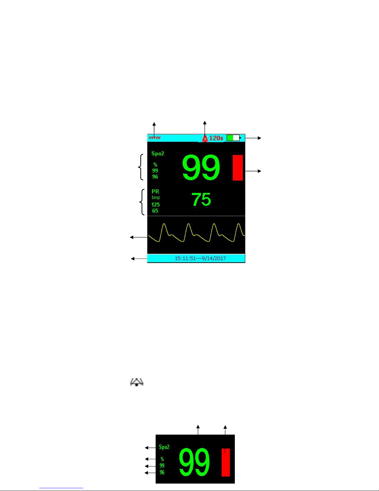
2.3 Screen Display
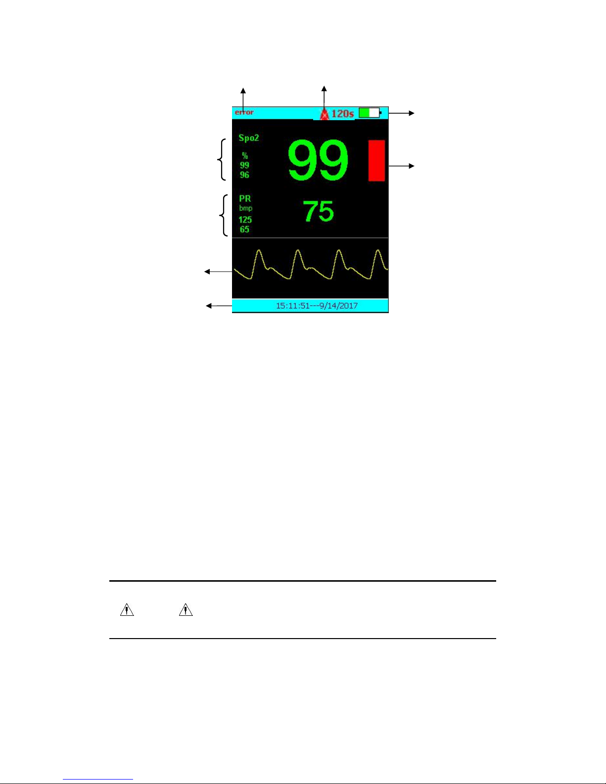
The following diagram shows the screen display interface.
1. Waveform area: Shows plethysmography (Pleth) waveform
2. SpO2 value display area
3. PR value display area
4. Physiological and technical alarms area
Display alarm information, tips and information on the operating mode.
Circle display when coming with multiple messages.
5. Alarm status area: indicates the alarm sound turned off.
6. Battery status icon
7. PI bar diagram
8. Time area
2.3.1 SpO2 value display Area
1
2
3
5
687
Page 15
12
1. Value Name
2. SpO2 value
3. PI bar graph
4. Low alarm limit
5. High alarm limit
6. Unit
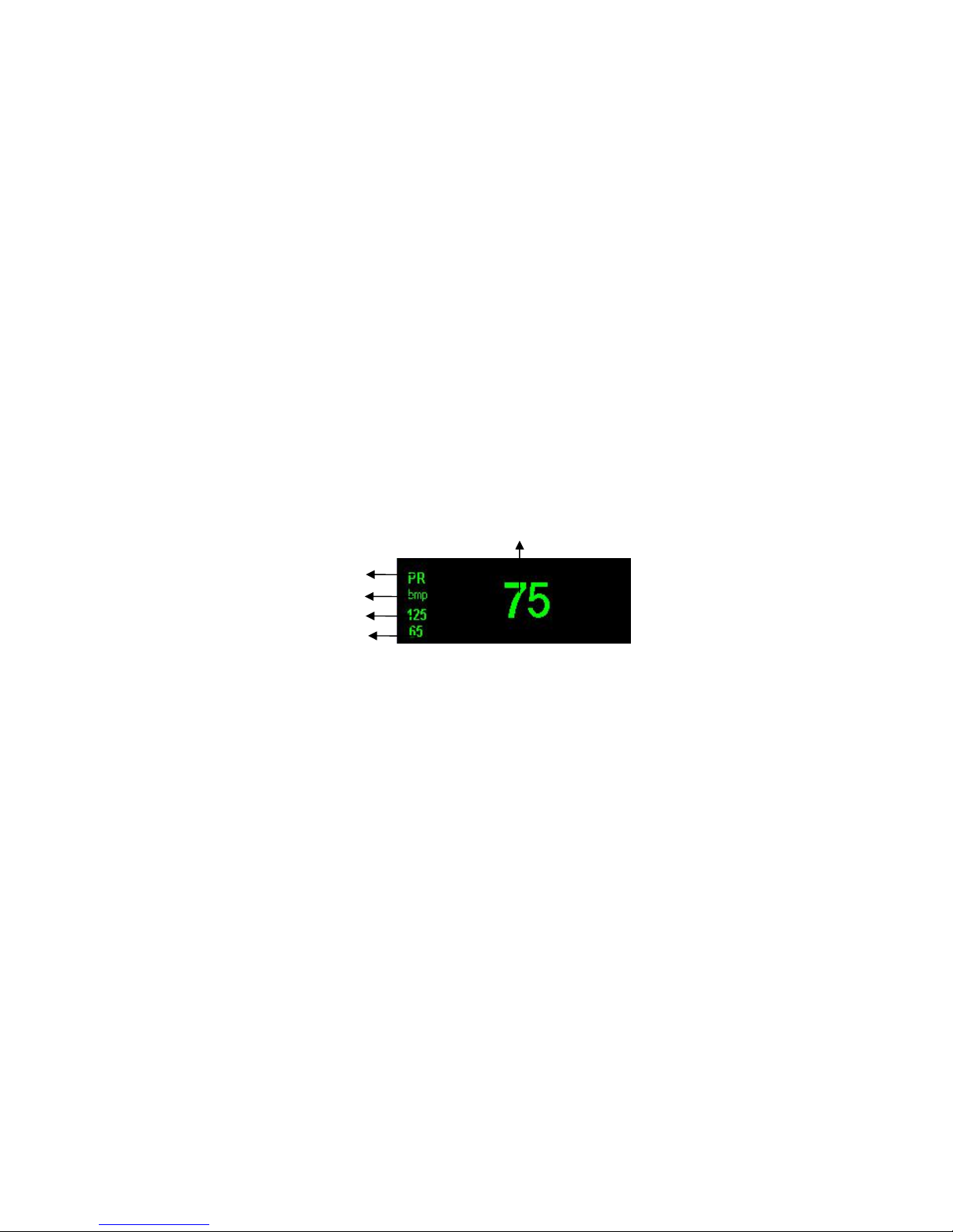
2.3.2 PR parameter area
1. Value Name
2. Unit
3. High alarm limit
4. Low alarm limit
5. PR value
3
Page 16

13
Chapter III Preparation before Use
3.1 Unpacking and Inspection
Take out the oximeter and accessories from the box carefully, and store the packaging in
case of future shipping or other use. Check the accessories according to the packing list.
If any damage happened, please contact our company’s after-sales department or agency
immediately.
Warning
Keep packaging material out of children’s reach. Concerning Disposal
packaging materials, waste disposal system must comply with relevant local
regulations or hospital’s claim.
3.2 Power On
1. Before starting, check whether the oximeter is mechanically damaged.
2. Make sure the battery has enough capacity.
3. Insert the oximeter cable into interface jack.
4. Press the power switch, and enter the boot screen.
5. Enter into the main interface after the boot screen disappearance.
Page 17

14
Warning
If find any function damage of oximeter, or get an error promotion, stop using
this oximeter anymore. And contact the biomedical engineer in hospital or
company’s maintenance engineer.
3.3Shutdown
Please refer to the following steps to turn off the oximeter:
1. Confirm that the work of monitoring patient comes to an end.
2. Disconnect the oximeter and oximeter cable.
3. Press the power switch and hold for two seconds to turn off the oximeter.
Chapter Ⅳ Menu Settings
The oximeter is designed with a flexible configuration. Both monitoring and alarm setting
could be free performed by user. Press the Menu key to bring up the main menu shown in
Figure 4-1.
Figure 4-1
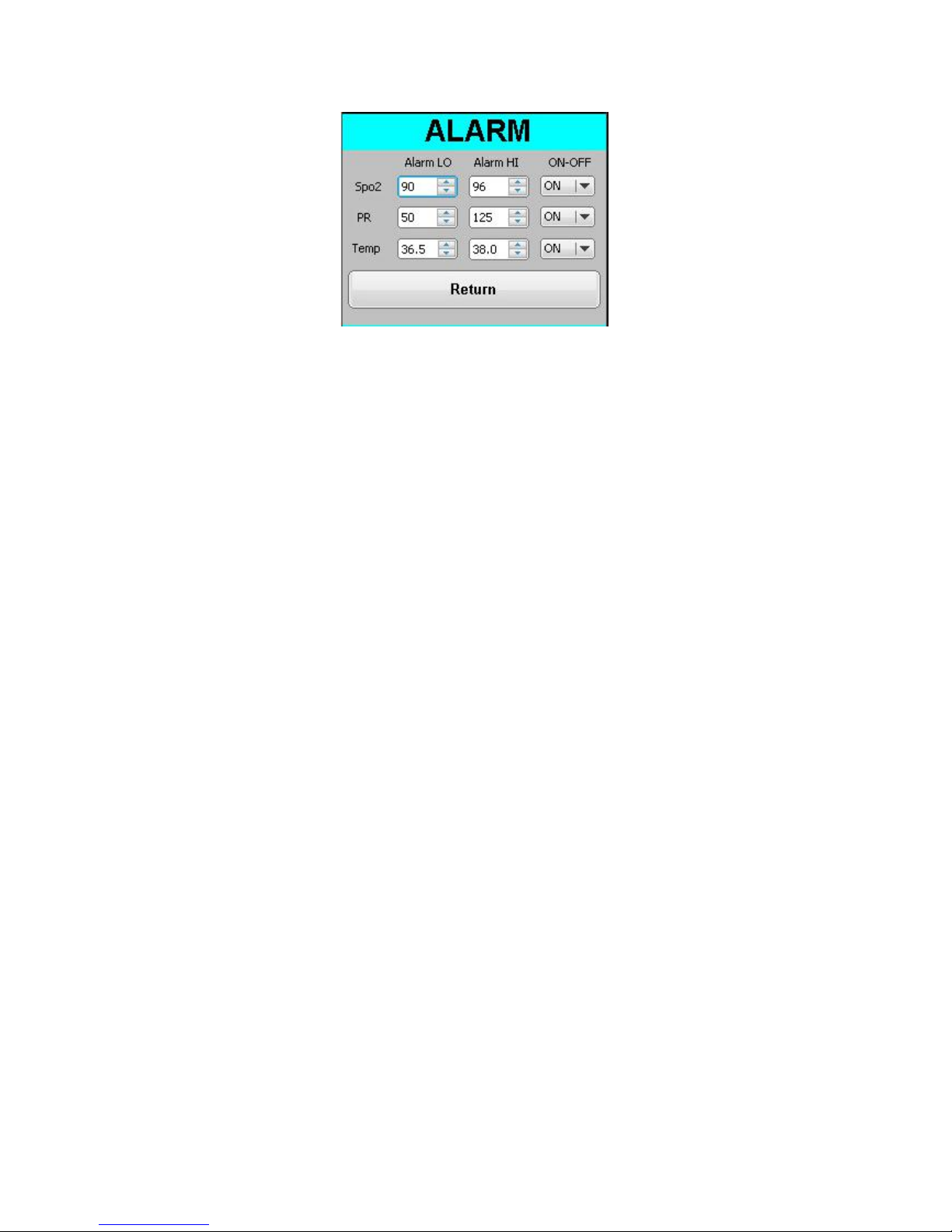
4.1 Alarm
Select "ALARM" in the main menu, and pop out a menu as shown in Figure 4-2:
Page 18
15
Figure 4-2
4.1.1 SPO2 Alarm
Choose SpO2 in Alarm menu
SPO2 adjustable range: Max: 100, Min:70
SPO2 Alarm:On/Off
Adjustment method:
Moving cursor via pressing 【 ▲ ,▼】, Choosing item as your need, then press【M 】 ,
Increase or decrease via pressing【▲ ,▼】. After your adjustment, pressing 【M】to
ensure it.
4.1.2 PR Alarm
Choose PR in Alarm menu
PR adjustable range: Max: 254, Min: 0
SPO2 Alarm:On/Off
Adjustment method same as 4.1.1
4.1.2 Temp Alarm (optional)
Choose Temp in Alarm menu
Temp adjustable range: Max: 50, Min: 20
SPO2 Alarm:On/Off
Adjustment method same as 4.1.1
Page 19
16
4.2 Setup
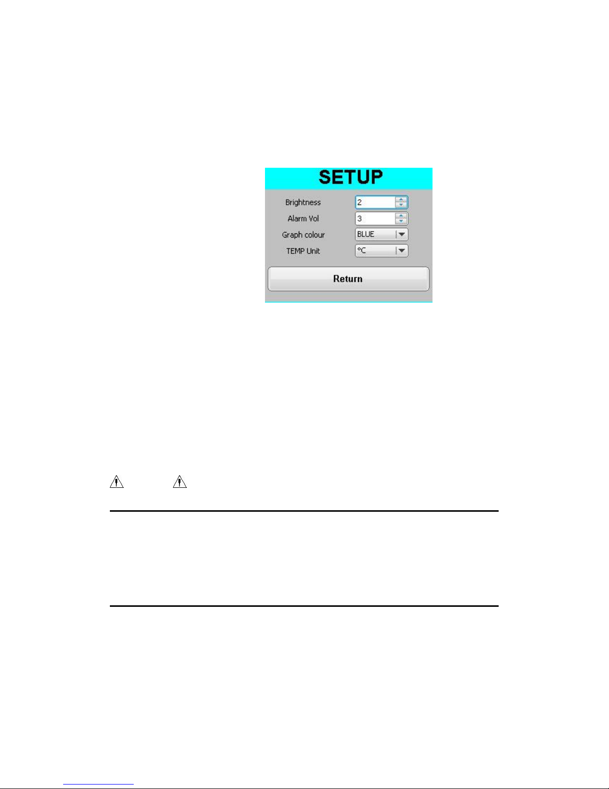
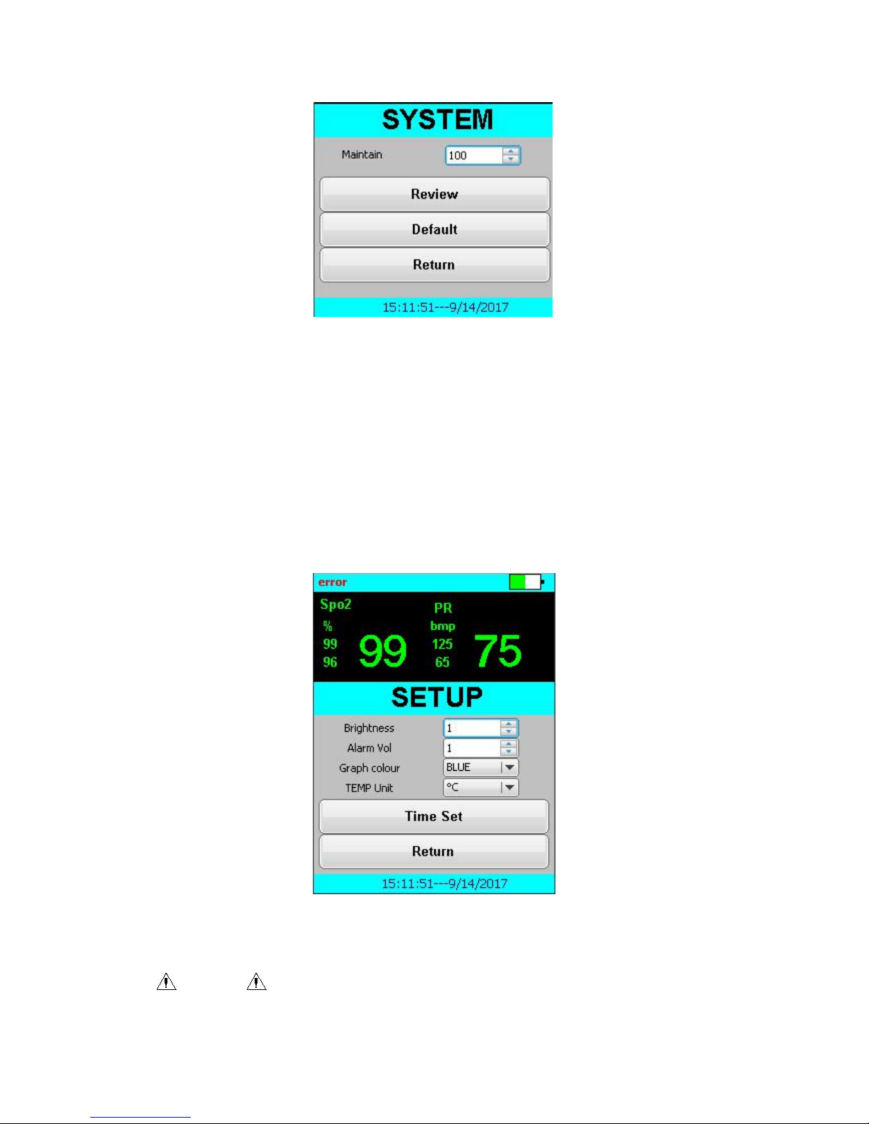
In the main menu, select [Setup], set up menu appears as Figure 4-3 below. In the
settings menu there are [Pulse Vol] , [Alarm Vol] and [TEMP Unit].
Figure 4-3
Users can modify the pulse and alarm volume, Temp unit as needed.
Choose【Brightness】in【SETUP】, adjusting via pressing 【▲,▼】. Options have
nice levels as “1”,“2”,“3”,“4”,“5”,“6”,“7”,“8”,“9”.
In the [Setup] menu, select the [alarm vol], Press【▲ ,▼】 to select the level of the
alarm volume . The options have five levels as "1", "2", "3" , "4", "5".
In the [Setup] menu, select the [TEMP unit] ,Press【▲,▼】to modify TEMP unit. The
options include “℃”and“℉”
Attention
If used outdoors or ambient light, please increase the screen brightness for
observation
Use Alarm Off button if you need to turn off the Alarm function.
4.3 System Setup
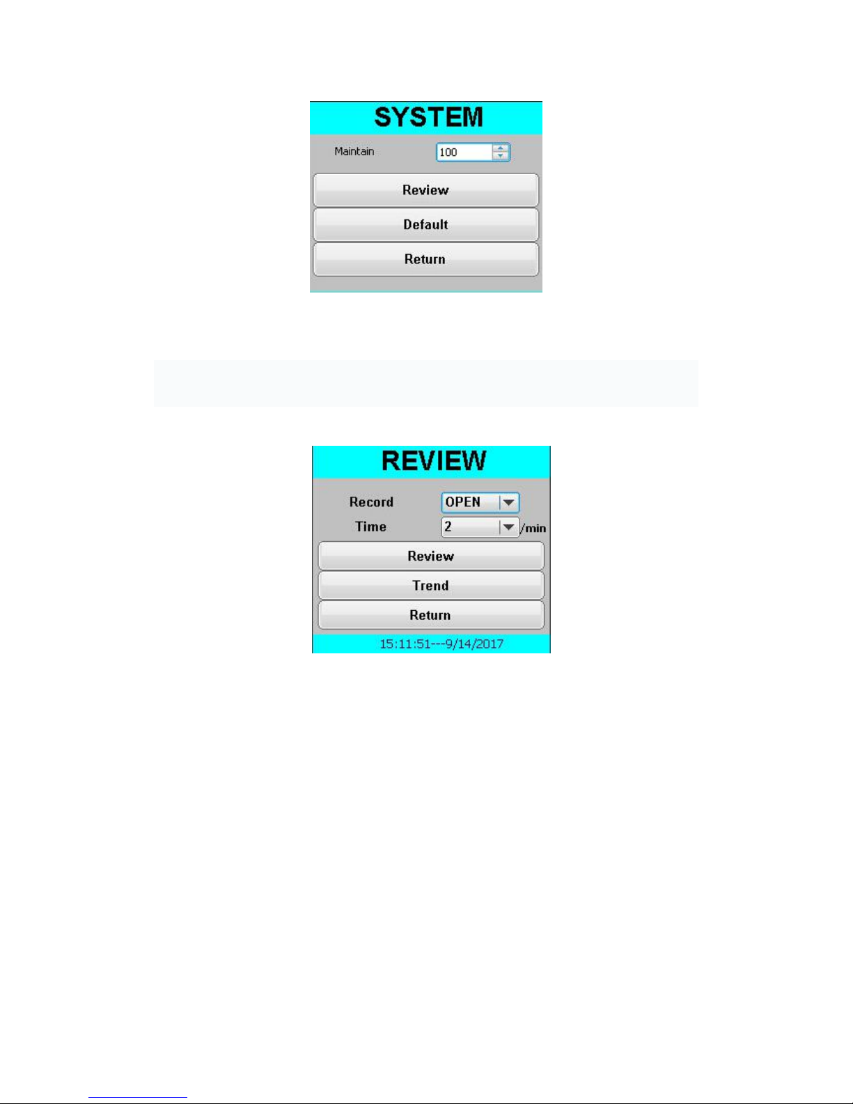
Select "SYSTEM" from the main menu, the system menu appears as shown in Figure
4-4. The 『System』 menu include [Review], [default ] and [Return] three options.
Page 20
17
Figure 4-4
4.3.1 Review
Choose【Review】in【SYSTEM】, you will see menu as Figure 4-5. You can setup record
Open or Close, and the recording period (Time) in【Review】menu.
图4-5 历史回顾
Page 21
18
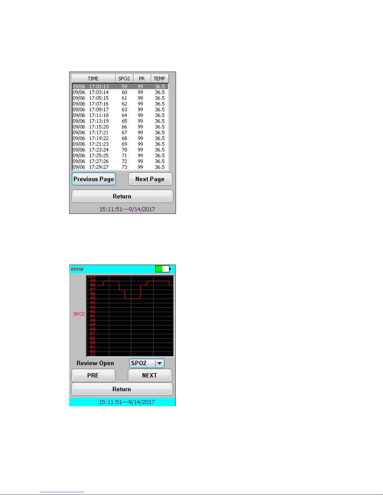
Choose【Trend】in【Review】, you will see menu as Figure 4-6.
图4-6 Trend
This device can review 500groups history data.
Choose【Previous Page】in【Trend】, you will see menu as Figure 4-7.
图4-7 Review
You can choose SPO2, PR, TEMP in【Review Open】read.
【PRE】to read the previous page
Page 22
19
【NEXT】to read the next page
4.3.2 Default Setup
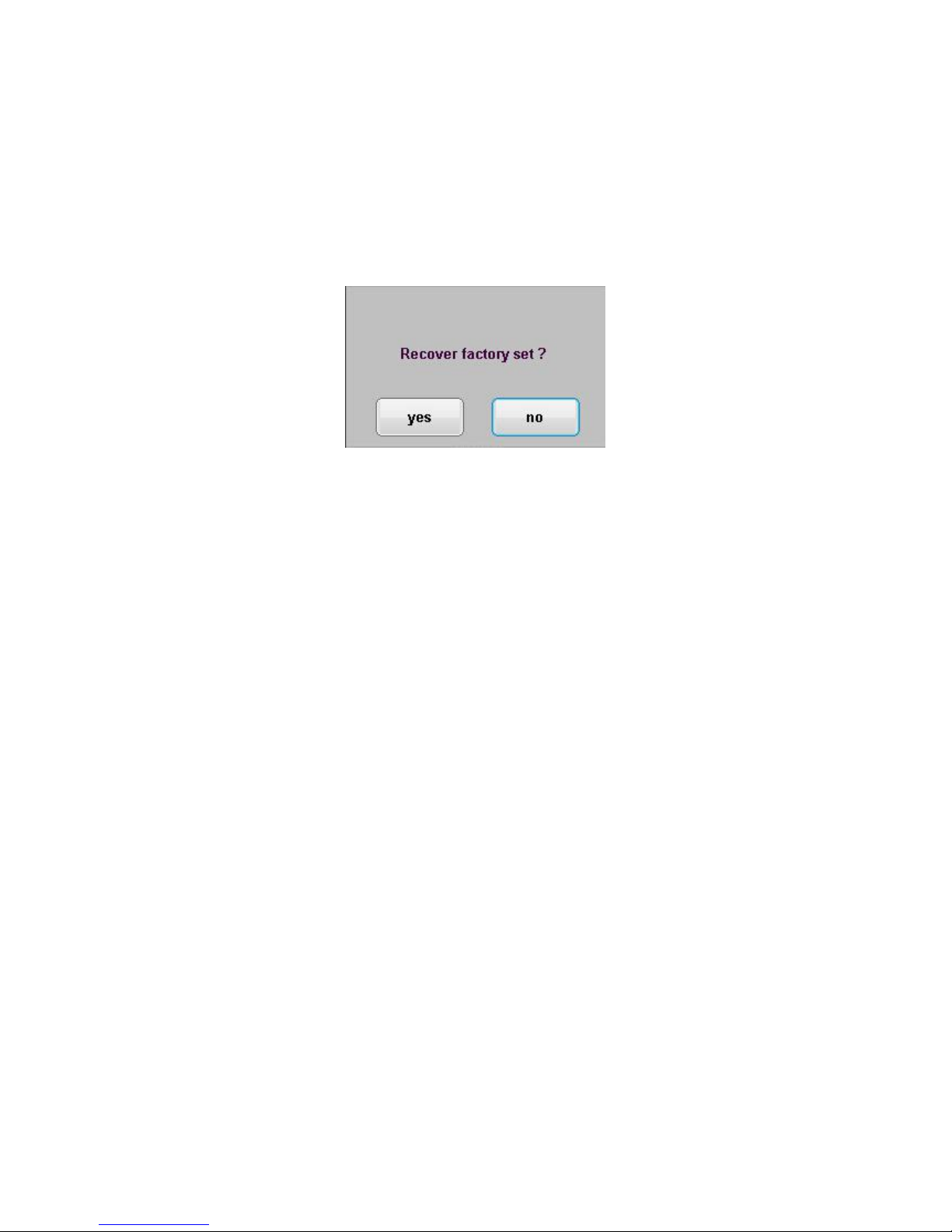
In the system menu, selecting Default will pop up the "Recover factory set" dialog box,
as shown in Figure 4-8.
Figure 4-8
Select 【Yes】 to recover factory set.
Select 【No】 to quit the current operation, and the system remains unchanged original
configuration.
4.3.3 Manufacturer Maintenance
In the [System Setup], select the [Maintenance] item, and pop out a dialog box, as shown
in Figure 4-9.
Users can input specific user password to active advanced settings in user maintenance
menu.
“Factory Maintenance” function only opens to the company's designated maintenance
personnel.
Page 23
20
Figure 4-9
4.4 Time Setup
Choose【Time Set】in【SETUP】, menu as Figure 4-10.
Figure 4-10
Attention
Page 24

21
When exiting the [manufacturer maintenance], it will return to the
sub-dialog box [Setup] menu; besides, all dialog boxes will exit to the
[main menu].
Chapter V Alarm
Alarm refers to tips made by the monitor to medical staff through sound, light
and other means when abnormal vital signs change is observed, or patients
cannot be monitored smoothly due to the failure of the monitor oximeter itself.
5.1 Alarm Type
Alarm can be classified into two categories which are physiological alarm and
technical alarm. When the alarm comes from the changes in the patient's vital
signs, namely, the physiological parameters of the patient being under care
exceed a specific range or the patient’s physiological abnormalities cannot be
attribute to one single physiological parameter beyond the range, it can be
referred to as physiological alarm; when the alarm is from the machine itself,
namely, when there are technical barriers existed in the alarm or the machine
itself breaks down, as a result, the patient cannot be observed accurately, it is
referred to as technical alarm.
Patient or machine
Alarm category
Heart rate of the patient is 114BPM, beyond the
range of heart rate alarm which is set by the user.
Physiological alarm
SpO2 measurement module fails
Technical alarm
Physiological alarm: the alarm light is normally on and the parameters on
the screen will flash with sound alarms accompanied.
Technical alarm: the alarm light is normally on with sound alarms
accompanied.
5.2 Alarm Status Icon
Besides the alarm types mentioned above, the following alarm icons will
appear on the screen which means different alarm states.
Page 25

22
: the state when alarm tone stops.
: the state when alarm turns off.
5.3 Alarm Pause
Press the
【▲】
button, the alarm tone can be paused:
The alarm is suspended while the alarm light and alarm information
continue display.
The state bar on the screen shows the left time of the alarm tone.
The state bar on the screen shows icon.
5.4 Set Alarm Sound
Select the【Menu】→【Setup】→【Alarm Volume】→ adjust the volume
(Max 5, Min 1).
After the oximeter is turned off and restarted, the minimum alarm volume set
will not change.
Warning
When the alarm volume is adjusted to 0, the alarm sound is off.
Patients cannot be monitored and cared only by the sound alarm
system. When the alarm sound is adjust to a relatively small volume,
patients can be in a dangerous condition. Users should pay close
attention to the actual clinical condition of patients.
5.5 Countermeasures to The Alarm
In case that the oximeter sends out an alarm, please refer to the following
steps to take appropriate measures:
1. Check the patient's condition.
2. Verify that the parameters of the ongoing alarm or the types of alarm.
3. Identify the reasons of the alarm.
4. Remove the reasons of the alarm.
5. Check whether the alarm is eliminated.
Page 26

23
For the specific treatment measures for each alarm, please refer to Appendix
C Alarm information.
Chapter
Ⅵ
SpO2
6.1 Overview
A continuous and non-invasive pulsation oximeter quantitative method is adopted for
SpO2 measurement. It measures the specific wavelength of light from the light source of
oxygen saturation probes, and after it is absorbed by oxyhemoglobin in the patient’s tissue
and reaches the luminous flux of photodetector end, thus to get oxygen saturation and
pulse rate. The oximeter has been calibrated and is used to display functional oxygen
saturation. The interface is as shown in Figure 7-1
Page 27
24
1
2
3
568
7
Figure 7- 1 SpO2 measurement interface
Measurements provide:
1. Arterial oxygen saturation (SpO2): the percentage of oxyhemoglobin in the total
hemoglobin.
2. Perfusion bar graph: proportional to the intensity of pulse.
3. Pulse rate (PR): the number of pulse detected per minute (obtained from
plethysmography waveform).
4. Plethysmography (Pleth) waveform: the strength of the patient’s pulse signal does not
affect the amplitude of Pleth waveform.
6.2 Safety Information
Warning
Influence from carboxyhemoglobin, methemoglobin or dye dilution
chemicals will cause biased SPO2 value.
Do not use any other SpO2 probe except the specified model in this
Page 28

25
manual, as well ensure that all operations are under the instruction of
the manual. Observe all warnings and precautions.
Before starting to monitor and care, firstly check whether the oxygen
probe is normal. If the oxygen probe packaging or the probe has
been damaged, do not use this oxygen probe.
If a patient has a tendency to hypoxia, the oximeter should be used to
analyze the oxygen probe, because the induced current may cause
serious burns of the patient.
When the patient is under continuous long-term monitoring, finger
position in the oxygen probe should be checked once every two
hours, meanwhile move patient’s hand every 4 hours or when a
change occurred to patient’s skin. Continuous long-term monitoring
may increase risk of patient’s unpredictable skin changes, such as
allergies, reddening, blistering or oppression necrosis.
The cables of electrosurgical devices cannot be entwined with
oximeter cable.
Do not mount and place the oxygen probe on the limbs with arterial
ducts or intravenous tubes.
Do not place the oxygen probe and blood pressure cuff on the same
limb.
For the patients younger than one-year-old, do not use the device
when the ambient temperature above 40 degrees Celsius to avoid
burning baby’s skin.
If the sensor packaging or sensor has been damaged, do not use this
Sp02sensor, and it should be returned to the manufacturer.
6.3 Caring Stepsbin
1. Select the appropriate oxygen probe according to the patient’s type and weight.
2. Clean the measurement site, such as colored nail polish.
Page 29

26
3. Place the oxygen probe at the measurement site.
4. Connect the oximeter and oximeter cable.
6.4 On/ Off Parameter Alarm
1. Select the [Menu] → [alarm]→[SPO2 alarm]
2. Set SPO2 or PR alarm to:
[On]: When the measured parameter has alarm event, the machine will have alarm
indication;
[Off]: No alarm indication when the menu is seted to off. Alarm sound, light and
indication to be closed at the same time. There will be a sign in the SPO2 or PR
parameter area.
6.5 Set Alarm Limits
1. Select the [Menu] → [alarm]→[SPO2 alarm]
2. Set the [High Limit] of SpO2 or PR: When the measured parameter value is above the
high alarm limit, a physiological alarm of too high parameters will be triggered.
3. Set the [Low Limit] of SpO2 or PR: When the measured parameter value is below the
low alarm limit, a physiological alarm of too low parameters will be triggered.
In case that a parameter alarm occurs, the measured value of the parameter will flash and
the appropriate alarm light will be triggered.
6.6 Measuring Influence Factors
If the accuracy of the measurement results is suspected, first use other methods to
examine the patient's vital signs, and then test the oximeter and oxygen probe. In the
measurement process, the following factors may affect the accuracy of measurements:
Outside light radiation
Body movement (active or passive patient movement)
Diagnostic test
Weak perfusion
Page 30

27
Electromagnetic field effects, such as nuclear magnetic
resonance device
Electrosurgical devices
Concentration of non-functional hemoglobin, such as carboxyhemoglobin (COHb)
and methemoglobin (MetHb)
Presence of certain dyes, such as methylene blue and indigo rouge, inappropriate
placement of oxygen probe or incorrect use of oxygen probe
Shock, anemia, low temperature or application of vasoconstrictor drugs leads to
reduced pulse blood flow in the water that can not be measured
Chapter VII of temperature (TEMP) (optional)
7.1 Temperature Monitoring Operation Steps (Optional)
Oximeter temperature probe can be used to measure the body temperature
data.
1. If you are using a disposable temperature probe, insert the cable’s right side
into socket and connect the other side with probe. For reusable temperature
probe, you can plug it directly into the socket.
2. The temperature probe firmly attached to the patient.
3. Connect the oximeter and temperature cable.
Page 31
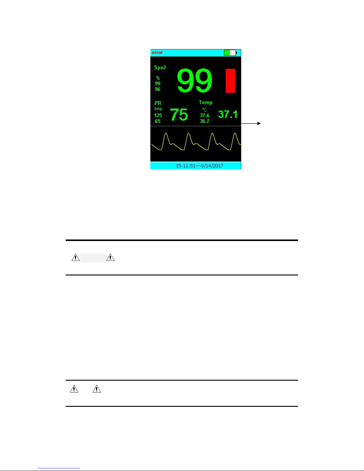
28
Temperature measurement interface shown in Figure 8-1.
Figure 8-1 temperature measurement interface
7.2 Safety Information
Warning
Should be tested before the start of the measurement probe cable is
normal. Unplug the temperature probe cable from the jack, the screen will
display the error message "T sensor off" and an alarm sounds. Similar to
other channels.
Place carefully temperature probe and cable when not in use, probe and
cable should be rolled into a loose ring. If the inside of the wire pull too
tight, it will cause mechanical damage.
Must biennial temperature measuring instrument calibration (or according
to hospital protocol indicates the time).
Note
Disposable temperature probe can only be used once. To protect the
environment, disposable temperature probe should be recycled or properly
Temperature
measurements
Page 32

29
disposed of.
During the measurement temperature measurement function self-test
automatically once per hour. Self-Test for 2 seconds, will not affect the
normal operation of the oximeter.
7.3 On / Off Parameters Alarm
1. Select【Menu】→【Alarm】→【Alarm temperature alarm】
2. Set the 【Alarm Temp】as follows:
【Open】:When this parameter alarm occurs, the oximeter will
alarm-related parameters;
【Off】:oximeter without alarm-related parameters, alarm sounds, alarm
lights and alarms are turned off, the display Temp parameter shows “ ”
icon.
7.4 Set the Alarm Limit
1. Select【Menu】→【Alarm】→【Alarm temperature alarm
】
2. Set Temp The【High Limit】:When the measured parameter value is above
the high alarm limit, an alarm will be triggered physiological parameters too
high.
3. Set Temp the【Lower limit】:When the measured value is below the low
alarm limit parameters, low physiological parameters will trigger an alarm.
When a parameter alarm occurs, This value will flash and corresponding
trigger an alarm lamp.
7.5 Setting The Temperature Unit
Select【Menu】→【Settings】→【TEMP unit】,options are "℃" and "℉"
Page 33

30
Chapter VIII Battery
8.1 Overview
The oximeter main power supplied is alkaline batteries. Icon in the top right
corner of the screen shows the battery status of the batteries.
When the battery is too low to display, you must replace the batteries or use
the AC adapter for power, after a period of time. Otherwise, oximeter will
automatically shut down. In the case of measuring the patient cannot be
interrupted, you can oximeter with the adapter and AC power.
Note
Remove the batteries before shipping oximeter or not use for a long time.
AC adapter power supply is available simultaneous use when you are using
batteries.
Warning
Keep out of the reach of children.
Use only the battery specified by the manufacturer.
8.2 Installing The Batteries
1. Hold the battery cover, push it down, remove the battery cover.
2. Install the batteries:
1) Press the batteries correct polarity into the batteries compartment;
2) The batteries cover on the top of the batteries, push up, install the battery
cover.
Be careful
Do not use different types of alkaline batteries.
Note
Battery run time depends on the device configuration and operation.
Page 34

31
8.3 Battery Recycling
If the battery is visibly damaged, or if the battery runs out of energy, should be
replaced, and properly recycled. When disposing of used batteries, should follow the
appropriate regulations.
Warning
Do not remove the battery, put it into a fire or short circuit. Battery burn,
explode or leak may cause personal injury.
Chapter Ⅸ Maintenance and Cleaning
Please merely use the materials and methods listed in this section for cleaning or
disinfecting of the device. The company does not provide any guarantee for damage or
accidents caused by other materials or methods.
The company does not bear any responsibility for the effectiveness of the chemicals or
methods listed as a means of infection control. About the method for infection control,
please consult the hospital’s infection prevention department or epidemiologist.
Please keep your devices and its’ accessories free of dust. To prevent damage to the
device, be sure to observe the following:
Please dilute the cleaning agent and disinfectant according to the manufacturer's
instructions, or use the lowest possible concentrations.
Do not immerse the device in the liquid.
Do not pour liquid onto the device or accessories.
Do not allow liquid to enter the enclosure.
Do not use abrasive materials (such as steel wool or silver polish), and any
strong solvents (such as acetone or acetone-containing cleaning agents).
Warning
Page 35

32
Before cleaning the device, you must turn off the power supply and disconnect
the power line and charger base.
Caution
If you pour liquid onto the device or accessories due to incaution, please
contact the maintenance personnel or the company immediately.
Attention
To clean or disinfect reusable accessories, please refer to the manual provided
along with the accessories.
9.1 Inspection
Before the oximeter is used for the first time, and after it is repaired or upgraded, or at
least every two years, a comprehensive inspection on it should be conducted by qualified
maintenance personnel to ensure the normal operation and work of the oximeter.
Inspection items should include:
The environment and power supply meet the requirements.
The device and accessories are not mechanically damaged.
The power line is not worn, with good insulation properties.
Use the specified accessories.
The alarm system functions properly.
Battery performance.
The monitoring function is in good working condition.
If you find any damage or unusual phenomenon, please do not use the oximeter, and
immediately contact the hospital's medical engineer or the company’s maintenance
personnel.
Page 36

33
9.2 Cleaning
The device should be cleaned on a regular basis, and the frequency of cleaning should be
increased in the areas suffering from serious environmental pollution or heavy sand.
Please consult or learn about the hospital’s regulations on the device cleaning before
cleaning.
The following cleaning agents are available for selection:
Diluted soapy water and diluted ammonia
Sodium hypochlorite (bleaching power for washing)
Hydrogen peroxide (3%)
Ethanol (70%)
Isopropanol (70%)
When cleaning the device:
1. Turn off the oximeter.
2. Use a soft cotton ball and adsorb the right amount of cleaning agent, and wipe the
display screen.
3. Use a soft cloth ball and adsorb the right amount of cleaning agent, and wipe the
surface of the device.
4. Use a dry cloth to remove excessive cleaning agent when necessary.
5. The device is placed in the ventilated, shade and dry environment.
9.3 Disinfection
Disinfection operation may produce some degree of damage to the oximeter. It is
recommended to perform disinfection only when deemed necessary in your hospital
maintenance plan. The device should be cleaned before disinfection.
The recommended disinfectants are: 70% ethanol, 70% isopropyl alcohol and 2%
glutaraldehyde solution.
Caution
Page 37

34
Do not use gas (EtO) or formaldehyde for disinfection.
9.4 Scrap
To avoid contamination or infection to others, environment or other devices, before
scrapping the oximeter, follow the state relevant laws or regulations for its disinfection and
purification. For the oxygen probe, please follow the relevant provisions of the local
hospital on waste scrap
Page 38
35
Chapter
Ⅹ
Accessories
Warning
Use only the accessories specified in this manual, and the use of
other accessories may damage the oximeter
Disposable accessories can only be used once, because repeated
use can cause performance degradation or cross-infection.
If accessory packages or accessories are damaged, do not use the
accessories.
The blood oxygen saturation probe in the chapter complies with
biocompatibility requirements and meets the standards ISO 10993-1
and ISO 10993-5 and ISO 10993-10.
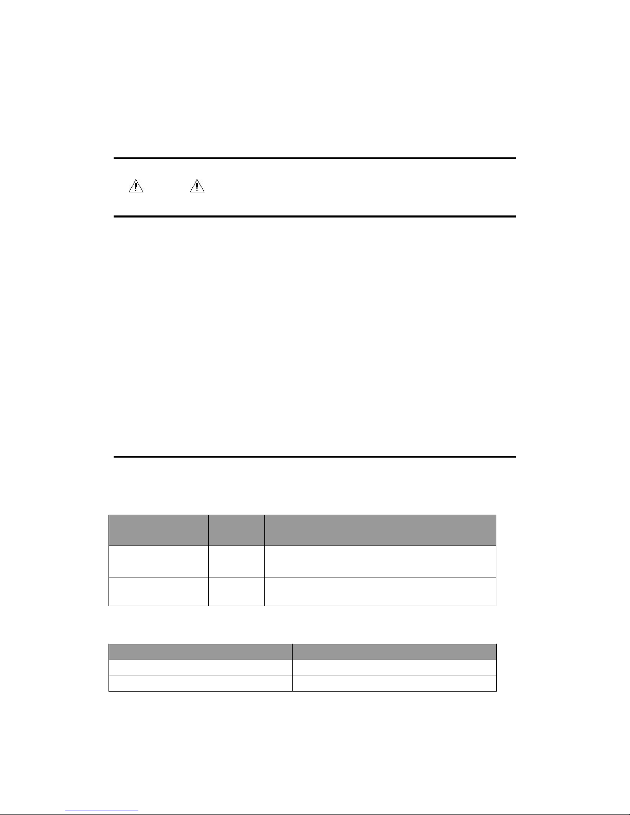
Blood oxygen saturation probe
Model
Applicabl
e object
Wavelength *
DB9 adult finger
clip
Adult
660nm 940nm
DB9 newborn wrap
Newborn
660 nm 905 nm
Others
Name
Model
Body temperature probe (optional)
Two core plastic plugs
Lithium battery
1.5V AAA
Page 39

36
A Product Specification
According to the classification standard of China's State Food and Drug Administration the
oximeter belongs to Class II device.
Safety specification (in accordance with IEC60601-1 classification)
Protection type of electric shock
Class II (including internal power supply)
Protection class of electric shock
BF (anti-defibrillator)
Explosion protection class
Ordinary device, explosion protection not provided
Protection class of inlet liquid
IPX2
Movement grade
Handheld
Working mode
Continuous
Environmental specification
Work
Storage
Temperature(℃)
0~40
-20~60
Relative humidity (non-condensing)
15%~95%
10%~95%
Atmospheric pressure (mmHg or
kPa)
425 ~ 809 mmHg or 70.0 ~
106.0 kPa
120 ~ 809mmHg or 22.0 ~
107.4 kPa
Alkaline battery
Page 40

37
Quantity
3 pcs
Standard
1.5V AAA
Supply time
6h, using the new and fully charged battery at the ambient
temperature 25℃, with a typical configuration (SpO2
continuous measurement, the backlight set to minimum
brightness, and the sound turned off all the time).
Shutdown delay
At most 10 minutes(since the first low battery capacity alarm)
Physical specification
W × H ×T
127×67×27 mm
Maximum weight
110g(net weight)
Hardware specification
Display screen
Color TFT, 2.4-inch, dot matrix: 240× 320
Speaker
1, alarm sound (45 ~ 85dB), multi-level volume function; alarm
sound in line with the requirements of IEC 60601-1-8 standard
Alarm indicator light
1, yellow
Power indicator light
1, green
Blood oxygen probe interface
1, D 9-pin socket
Temperature probe interface
1 (optional)
Micro USB interface
1, connect adapter
Measurement specification
SpO2
Confirm the accuracy of measurements: the accuracy of SpO2 is already confirmed in human trials by
comparison with the reference value of arterial blood sample measured by CO- oxygen pressure
Page 41

38
gauge. The measurement results of pulsation oxygen meter meet statistical distribution, and compared
with the measurement results of CO- oxygen pressure gauge, only about two-thirds of the
measurement results is expected to be within the specified precision.
Measuring range
0~100%
Resolution
1%
Precision
70~100%: ± 2% (adults, in the non-moving state)
± 3% (in the moving state)
0%~69%:not defined
Update cycle
1 s
PR
Measuring range
18~300 bpm
Resolution
1 bpm
Precision
±3 bpm (in the non-moving state)
±5 bpm(in the moving state)
Update cycle
1 s
Alarm limit specification
Alarm limit
Range(%)
Step length(%)
SpO2 high limit
(low limit +1)~100
1
SpO2 low limit
50~(high limit -1)
Alarm limit
Range(bpm)
Step length(bpm)
PR high limit
(low limit +1)~300
1
PR low limit
18~(high limit -1)
Measurement specification
Page 42
39
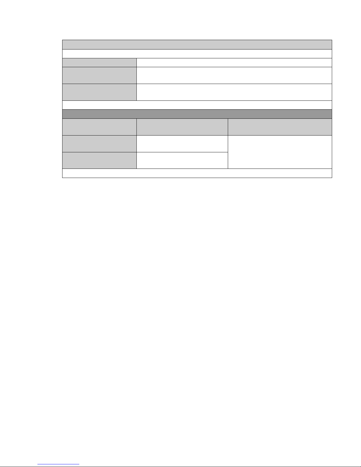
TEMP
Measuring range
0~50 ℃
Resolution
0.1 ℃
Precision
±0.1 ℃
Alarm limit specification
Alarm limit
Range(℃)
Step length(%)
TEMP high limit
(low limit+1)~50
1
TEMP low limit
0~(high limit-1)
Page 43

40
B Default factory settings
This chapter lists some of the most important default factory settings of the oximeter. If
users can not change the factory settings, but when needed, the default factory settings of
the oximeter can be restored.
B.1 Alarm
Alarm setting
Default factory settings
Alarm volume *
1
Pause time for alarm tone
120 s
Alarm switch
open
Probe off
low
SPO2 alarm
open
PR alarm limit
open
B.2 SpO2
SpO2 Settings
Adults
SpO2 high alarm limit
100
SpO2 PR low alarm limit
90
Page 44
41
PR Settings
Adults
PR high alarm limit
120
PR low alarm limit
50
Temp setting
adults
Temp high alarm limit
38.0
Temp ow alarm limit
35.5
C Alarm Information
This chapter lists some of the most important physiological and technical alarm
information, but some alarm information is not necessarily listed.
For each alarm information, appropriate countermeasures are given out. If the problem
persists after operations following the countermeasures, contact the maintenance
personnel.
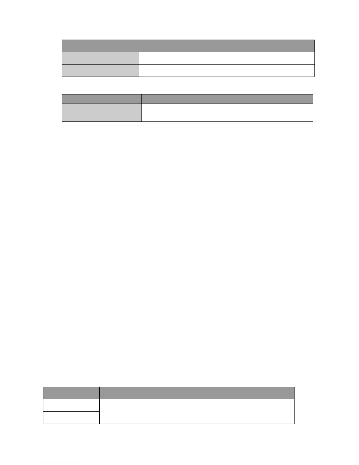
Alarm information
Reasons and countermeasures
SpO2 too high
Check the physiological condition of the patient, and confirm whether the
SpO2 too low
Page 45

42
C.1 Physiological alarm information
C.2 Technical alarm information
Alarm information
Reasons and countermeasures
probe off
If the oxygen probe is off from the patient or host, if it fails, or an oxygen
probe not specified in this manual is used, check whether the oxygen
probe type and installation position are correct, and whether the oxygen
probe is damaged. Reconnect the oxygen probe or use a new oxygen
probe.
patient type and alarm limit settings are applied to the patient.
PR too high
PR too low
No pulse found
If the patient's pulse signal is too weak, the system can not analyze.
Check the patient's condition, oxygen probe and measurement site.
Temp too high
Check the physiological condition of the patient, and confirm whether the
patient type and alarm limit settings are applied to the patient.
Temp too low
Page 46

43
Inadequate battery
capacity
When the low battery voltage is below the alarm voltage, if the battery in
use is alkaline battery, replace the battery immediately. If the battery in
use is a lithium battery, connect the charger base and AC power supply to
recharge the lithium battery, and then use the battery to supply power as
needed.
D Manufacturer’s Declaration of the EUT
Guidance and manufacturer´s declaration – electromagnetic emission –
for all EQUIPMENT AND SYSTEMS
1
Guidance and manufacturer´s declaration – electromagnetic emission
2
The Palm Pulse Oximeter is intended for use in the electromagnetic environment specified below.
The customer or the user of Palm Pulse Oximeter should assure that it is used in such an
environment.
3
Emissions test
Compliance
Electromagnetic environment - guidance
4
RF emissions
CISPR 11
Group 1
The Palm Pulse Oximeter uses RF energy only for its
internal function. Therefore, its RF emissions are very low
and are not likely to cause any interference in nearby
electronic equipment.
5
RF emissions
CISPR 11
Class B
The Palm Pulse Oximeter is suitable for use in all establi
shments, including domestic establishments and those dir
ectly connected to the public low-voltage power supply ne
twork that supplies buildings used for domestic purposes.
6
Harmonic
emissions
IEC 61000-3-2
N/A
7
Voltage fluctuations
/flicker emissions
IEC 61000-3-3
N/A
Guidance and manufacturer's declaration – electromagnetic immunity –
for all EQUIPMENT and SYSTEMS
Page 47

44
Guidance and manufacturer´s declaration – electromagnetic immunity
The Palm Pulse Oximeter is intended for use in the electromagnetic environment specified below. The
customer or the user of the Palm Pulse Oximeter should assure that it is used in such an environment.
Immunity test
EN 60601
test level
Compliance level
Electromagnetic environment -
guidance
Electrostatic
discharge (ESD)
IEC 61000-4-2
± 6 kV contact
± 8 kV air
± 6 kV contact
± 8 kV air
Floors should be wood, concrete or
ceramic tile. If floors are covered
with synthetic material, the relative
humidity should be at least 30 %.
Electrostatic
transient / burst
IEC 61000-4-4
± 2 kV for power
supply lines
±1 kV for input/output
lines
N/A
Mains power quality should be that
of a typical commercial or hospital
environment.
Surge
IEC 61000-4-5
± 1 kV differential
mode
± 2 kV common
mode
N/A
Mains power quality should be that
of a typical commercial or hospital
environment.
Voltage dips,
short
interruptions and
voltage
variations
on power supply
input lines
IEC 61000-4-11
< 5 % U
T
(>95 % dip in UT)
for 0.5 cycle
40 % U
T
(60 % dip in UT)
for 5 cycles
70 % U
T
(30 % dip in UT)
for 25 cycles
< 5 % U
T
(>95 % dip in UT)
for 5 sec
N/A
Mains power quality should be that
of a typical commercial or hospital
environment. If the user of the
Palm Pulse Oximeter requires
continued operation during power
mains interruptions, it is
recommended that the Palm Pulse
Oximeter be powered from an
uninterruptible power supply or a
battery.
Power
frequency
(50/60 Hz)
magnetic field
IEC 61000-4-8
3 A/m
3 A/m
Power frequency magnetic fields
should be at levels characteristic of
a typical location in a typical
commercial or hospital
environment.
NOTE UTis the a. c. mains voltage prior to application of the test level.
Page 48
45
Guidance and manufacturer´s declaration – electromagnetic immunity –
for EQUIPMENT and SYSTEM that are not LIFE-SUPPORTING
Guidance and manufacturer´s declaration – electromagnetic immunity
The Palm Pulse Oximeter is intended for use in the electromagnetic environment specified below. The
customer or the user of the Palm Pulse Oximeter should assure that it is used in such an environment.
Immunity test
EN 60601 test
level
Compliance
level
Electromagnetic environment - guidance
Conducted RF
IEC 61000-4-6
Radiated RF
IEC 61000-4-3
3 Vrms
150 kHz to 80 MHz
3 V/m
80 MHz to 2.5 GHz
N/A
3 V/m
Portable and mobile RF communications
equipment should be used no closer to any
part of the Palm Pulse Oximeter including
cables, than the recommended separation
distance calculated from the equation
applicable to the frequency of the transmitter.
Recommended separation distance
P
V
d ]
5.3
[1
P
E
d ]
5.3
[1
80 MHz to 800 MHz
P
E
d ]7[1
800 MHz to 2.5 GHz
where p is the maximum output power rating
of the transmitter in watts (W) according to the
transmitter manufacturer and d is the
recommended separation distance in metres
(m).
b
Field strengths from fixed RF transmitters, as
determined by an electromagnetic site
survey,ashould be less than the compliance
level in each frequency range.
b
Interference may occur in the vicinity of
equipment marked with the following symbol:
NOTE 1 At 80 MHz and 800 MHz, the higher frequency range applies.
NOTE 2 These guidelines may not apply in all situations. Electromagnetic is affected by absorption and
reflection from structures, objects and people.
a
Field strengths from fixed transmitters, such as base stations for radio (cellular/cordless) telephones
Page 49

46
and land mobile radios, amateur radio, AM and FM radio broadcast and TV broadcast cannot be predicted
theoretically with accuracy. To assess the electromagnetic environment due to fixed RF transmitters, an
electromagnetic site survey should be considered. If the measured field strength in the location in which the
Palm Pulse Oximeter is used exceeds the applicable RF compliance level above, the Palm Pulse Oximeter
should be observed to verify normal operation. If abnormal performance is observed, additional measures
may be necessary, such as reorienting or relocating the Palm Pulse Oximeter.
b Over the frequency range 150 kHz to 80 MHz, field strengths should be less than 3V/m.
Recommended separation distances between portable and mobile
RF communications equipment and the EQUIPMENT or SYSTEM -
for EQUIPMENT and SYSTEMS that are not LIFE-SUPPORTING
Recommended separation distances between
portable and mobile RF communications equipment and the Palm Pulse Oximeter
The Palm Pulse Oximeter is intended for use in an electromagnetic environment in which radiated RF
disturbances are controlled. The customer or the user of the Palm Pulse Oximeter can help prevent
electromagnetic interference by maintaining a minimum distance between portable and mobile RF
communications equipment (transmitters) and the Palm Pulse Oximeter as recommended below,
according to the maximum output power of the communications equipment
Separation distance according to frequency of transmitter
m
Rated maximum
output of
transmitter
W
150 kHz to 80 MHz
P
V
d ]
5.3
[1
80 MHz to 800 MHz
P
E
d ]
5.3
[1
800 MHz to 2.5 GHz
P
E
d ]7[1
0.01/0.12
0.23
0.1/0.38
0.73
1/1.2
2.3
10/3.8
7.3
100/12
23
For transmitters rated at a maximum output power not listed above the recommended separation distance
d in metres (m) can be estimated using the equation applicable to the frequency of the transmitter, where
P is the maximum output power rating of the transmitter in watts (W) according to the transmitter
manufacturer.
NOTE 1 At 80 MHz and 800 MHz, the separation distance for the higher frequency range applies.
NOTE 2 These guidelines may not apply in all situations. Electromagnetic propagation is affected by
absorption and reflection from structures, objects and people.
 Loading...