

Boxlight Corporation SE 55HD User Manual
D2+ DLP
H
User's Manual
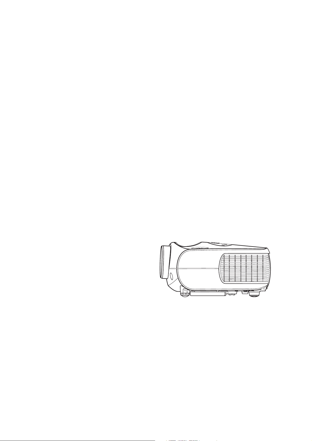
Front Projector
HD2+ DLP Front Projector

Preface
ENGLISH
ABOUT THIS MANUAL
This manual is designed for use with the HD2+ DLP Front Projector. Information in this document has
been carefully checked for accuracy; however, no guarantee is given to the correctness of the
contents. The information in this document is subject to change without notice.
COPYRIGHT
© Copyright 2004
This document contains proprietary information protected by copyright. All rights are reserved. No part
of this manual may be reproduced by any mechanical, electronic or other means, in any form, without
prior written permission of the manufacturer
TRADEMARKS
All trademarks and registered trademarks are the property of their respective owners.
FCC COMPLIANCE
This device complies with Part 15 of the FCC Rules. Operation is subject to the following two
conditions:
(1) This device may not cause harmful interference, and
(2) This device must accept any interference received, including interference that may cause
undesired operation.
Preface
FEDERAL COMMUNICATIONS COMISSION (FCC) STATEMENT
This equipment has been tested and found to comply with the limits for a Class B digital device,
pursuant to part 15 of the FCC Rules. These limits are designed to provide reasonable protection
against harmful interference in a residential installation. This equipment generates, uses and can
radiate radio frequency energy and, if not installed and used in accordance with the instructions, may
cause harmful interference to radio communications. However, there is no guarantee that interference
will not occur in a particular installation. If this equipment does cause harmful interference to radio or
television reception, which can be determined by turning the equipment off and on, the user is
encouraged to try to correct the interference by one or more of the following measures:
Reorient or relocate the receiving antenna.
Increase the separation between the equipment and the receiver.
Connect the equipment to an outlet on a circuit different from that to which the receiver is connected.
Consult the dealer or an experienced radio/TV technician for help.
1
Notices
Preface
WARNING! To meet FCC requirements, a shielded power cord is required in order to prevent
interference. It is essential that only the supplied power cord is to be used. Use only shielded
cables to connect I/O devices to this equipment. You are cautioned that changes or
modifications not approved by the party responsible for compliance could void your authority
to operate the equipment.
WARNING! The projector cooling fan continues to run for approximately 90 seconds after the
projector is turned off using the Power button on the control panel or remote control. Never
unplug the power cable to power off the projector; damage to the lamp may result.
WARNING! High brightness light source. Do not stare into the beam of light, or view directly.
Be especially careful and ensure that children do not stare directly into the beam
of light.
WARNING! To reduce the risk of fire or electric shock, do not expose this product to rain or
moisture.
CAUTION! For minimal servicing and to maintain high image quality, we recommend that you
use the projector in an environment that is smoke and dust free. When used in areas where
there is a lot of smoke or dust, the filter and lens should be cleaned often to lengthen the
service life of the projector.
WARNING! Some IC chips in this product include confidential and/or trade secret property
belonging to Texas Instruments. Therefore you may not copy, modify, adapt, translate,
distribute, reverse engineer, reverse assemble or decompile the contents thereof.
WARNING! The ventilation slots, lamp, and objects next to them may get extremely hot
during operation. Do not touch these areas until they have sufficiently cooled down.
2
PRODUCT DISPOSAL
This projector utilizes a tin-lead solder, UHP Lamp containing a small amount of mercury. Disposal of
these materials may be regulated due to environmental considerations.
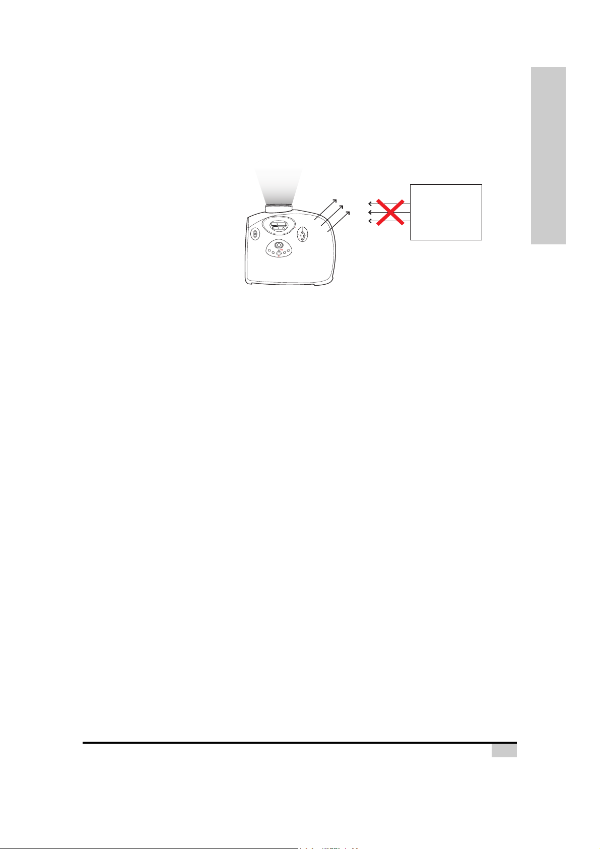
Caution regarding the exhaust of the projector.
Do not put Air Conditioners or
Flowers near the exhaust
vent.
Exhaust Vent
Air Conditioners
or Flowers
Focus
Zoom
(V)
LENS SHIFT
EXIT
ECO
(H)
LENS SHIFT
ENTER
STATUS
MENU
INPUT
Air flow
Before using the projector, please read this operation manual carefully.
To facilitate reporting the loss or theft of your Projector, record the Serial Number located on the
bottom of the projector and retain this information. Before recycling the packaging, be sure that you
have checked the contents of the carton thoroughly against the list of “Package Contents” on page 7.
WARRANTY
Promptly register the Projector’s Warranty using the REGISTRATION CARD packed with the
projector. The Warranty assures that you immediately receive the full benefit of the parts, service and
labor warranty applicable to your purchase.
Preface
3

Contents
Contents
Preface .............................................................................. 1
Notices .............................................................................. 2
Introduction
Package Contents ............................................................. 7
Features ............................................................................ 8
Components ...................................................................... 9
Projector (Front and Top View)............................. 9
Projector (Rear View).......................................... 10
Remote Control ................................................... 11
Using the Remote Control ............................................... 12
Available Range of the Remote Control .............. 12
Inserting the Batteries ......................................... 12
Connections and Setup
Connecting the Projector to Other Devices ..................... 14
Before Setting Up................................................ 14
Connecting the Power Cord ................................ 14
Connecting to Video Equipment...................................... 15
Connecting to Component Video Equipment ...... 16
Connecting Using the DVI Cable ........................ 16
Connecting Using a DVI-D to HDMI Cable..........17
Connecting the Projector to a Computer ......................... 18
Connecting the Cables .................................................... 19
“Plug and Play” Function ................................................. 19
Using the Adjustment Feet .............................................. 20
Adjusting the Lens........................................................... 21
Using the Lens Shift ........................................................21
Setting up the Screen...................................................... 22
Screen Size and Projection Distance .................. 23
Projection from behind the screen ...................... 25
Basic Operation
Image Projection ............................................................. 28
Basic Procedure.................................................. 28
Selecting the On-screen Display Language ........ 30
Menu Bar Items ............................................................... 31
Using the Menu Screen................................................... 33
Menu Selections (Adjustments) .......................... 33
Adjusting the Image......................................................... 34
Adjusting Computer Images ............................................ 38
Easy to Use Functions
Selecting the Picture Display Mode................................. 40
H-V Position Function...................................................... 43
4

H-V Keystone Function ................................................... 44
White Enhance ................................................................ 45
Selecting the Economy Mode.......................................... 45
Setting the Power Save....................................... 45
Automatic Power Off Function......................................... 46
Source Select .................................................................. 46
OSD Timeout................................................................... 47
OSD Blending.................................................................. 48
Reversing/Inverting Projected Images............................. 48
Setting the Projection Mode ................................ 48
Deinterlace ...................................................................... 49
Reset ...............................................................................50
Lamp Timer Reset........................................................... 50
Status Screen.................................................................. 51
Factory reset ...................................................................51
Appendix
Maintenance.................................................................... 54
Cleaning the Ventilative Holes ........................................55
Cleaning the Ventilative Holes ............................ 55
About the Lamp ............................................................... 56
Caution Concerning the Lamp ............................56
Replacing the Lamp ............................................ 56
Temperature LED (Over Temperature)............... 56
Removing and Installing the Lamp Unit........................... 57
Resetting the Lamp Timer ............................................... 58
Connecting Pin Assignments .......................................... 59
Computer Compatibility Chart ......................................... 60
Video Compatibility Chart................................................61
Troubleshooting............................................................... 62
Product Specifications..................................................... 64
Dimensions...................................................................... 65
Contents
5

Introduction
Introduction
6
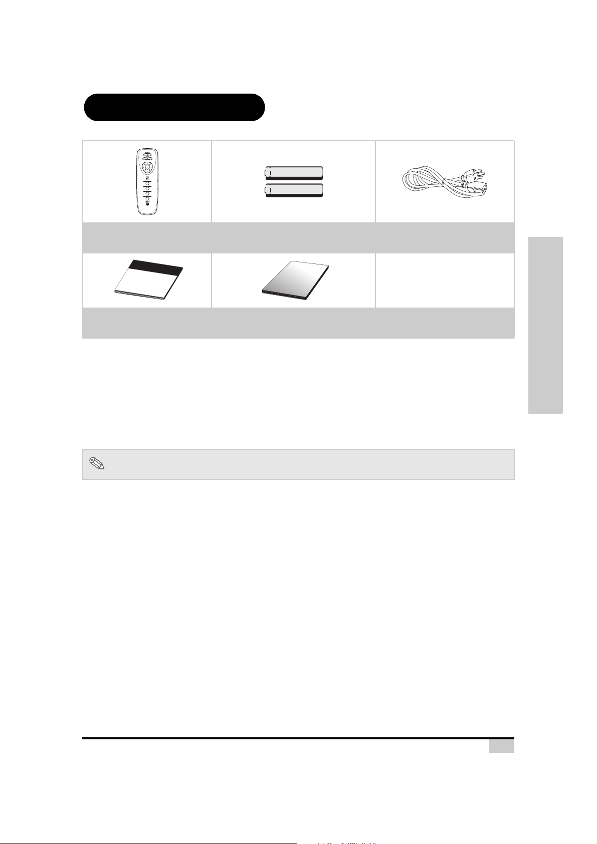
Package Contents
Open the package and ensure that you have the following items:
COMPONENT 1
COMPONENT 2
VIDEO/S-VIDEO
DVI/PC
Remote control Two “AAA” size batteries Power cord
(By country)
Quick Guide
T
h
i
s
M
a
tt
e
rh
o
r
n
D
L
P
F
R
O
N
T
P
R
O
J
E
C
T
O
R
m
a
n
u
a
l
m
a
y
n
o
t
b
©
e
A
c
o
l
p
l
i
e
r
i
d
g
i
n
h
t
a
s
n
y
r
m
e
s
e
e
d
i
r
a
v
o
ed
r
f
o
.
r
m
w
i
t
h
o
u
t
t
h
e
w
r
i
t
t
e
n
c
o
n
s
e
n
t
o
f
t
h
e
m
a
n
u
f
a
c
t
u
r
e
r
.
User's Manual
Quick Guide Operation manual
(this manual)
Optional accessories
HD 15-pin VGA to HD 15-pin VGA cable
RS-232C cable (3M)
DVI-D to DVI-D cable (3M)
DVI-D to HDMI cable (3M)
Ceiling mount package
Note
If anything is missing or appears damaged, contact your dealer immediately.
• Some of the cables may not be available depending on the region. Please check with
your nearest authorized dealer.
Introduction
7

Features
• Newly developed DMD™ chip provides significantly improved optical efficiency and excellent
contrast ratio.
• Newly developed LVDS (Low voltage differential signal) chip eliminates color breaking
phenomena common with previous generation DLP™ projectors.
• The 250W high-output lamp gives high color purity and brightness. Natural images are
possible with excellent color reproduction and powerful expression capabilities.
• Latest image quality circuitry gives you vivid images.
• New I/P conversion algorithm enhances motion.
• Extensive improvements in jagged edges and slanted lines in moving images.
• New Edge Up-Scaling.
• As a result of reducing jagged edges and flickering when up-scaling edges of slanted lines,
even signals not reaching a panel resolution of 480I/P can be projected by converting them to
1280 × 720 resolution images.
• New Film mode.
• 3:2 pull-down enhancement for 480I, 576I and HDTV 1080I signals.
• Use of a DVI/HDCP terminal enables all processes from input to signal processing and
projecting to be performed digitally. All-digital projection does not suffer the data loss of
analog conversion. Home theaters using HTPC are supported.
Introduction
8

Components
Projector (Front and Top View)
Focus ring
Adjusts focus.
Lens shift dial
(Vertical)
Press to set selected items or
Power (ON/OFF) buttons
Press to turn the power on or
ENTER button
adjustments in the menu.
Exit button
Press to exit the OSD.
ECO button
For power saving/
extended lamp life.
off.
Power indicator
Blue:
Blue flashing:
Standby mode.
The fan is
cooling.
LENS SHIFT
Zoom ring
Focus
Zoom
Adjusts screen display.
Lens shift dial
(Horizontal)
Introduction
(V)
EXIT
ENTER
STATUS
ECO
MENU
INPUT
LENS SHIFT
(H)
Adjustment buttons
(T,S,W,X)
Press to select menu items.
Temperature indicator
Red indicates the temperature of
the projector exceeds the set
critical temperature or when the
fan malfunctions.
MENU button
Press to open the OSD
menu.
INPUT button
Press to select the input
source.
Intake vent
Exhause vent
Adjustment foot
Remote control sensor
Adjustment foot
Temperature indicator
The projector has a temperature warning LED on the control panel. If the projector overheats because of a
dirty filter or another problem, the LED will flash, and the projector lamp will turn off, after which a 90-second
cooling off period occurs. After restarting the projector, if the unit doesn’t operate normally, take the projector
for servicing.
9
/
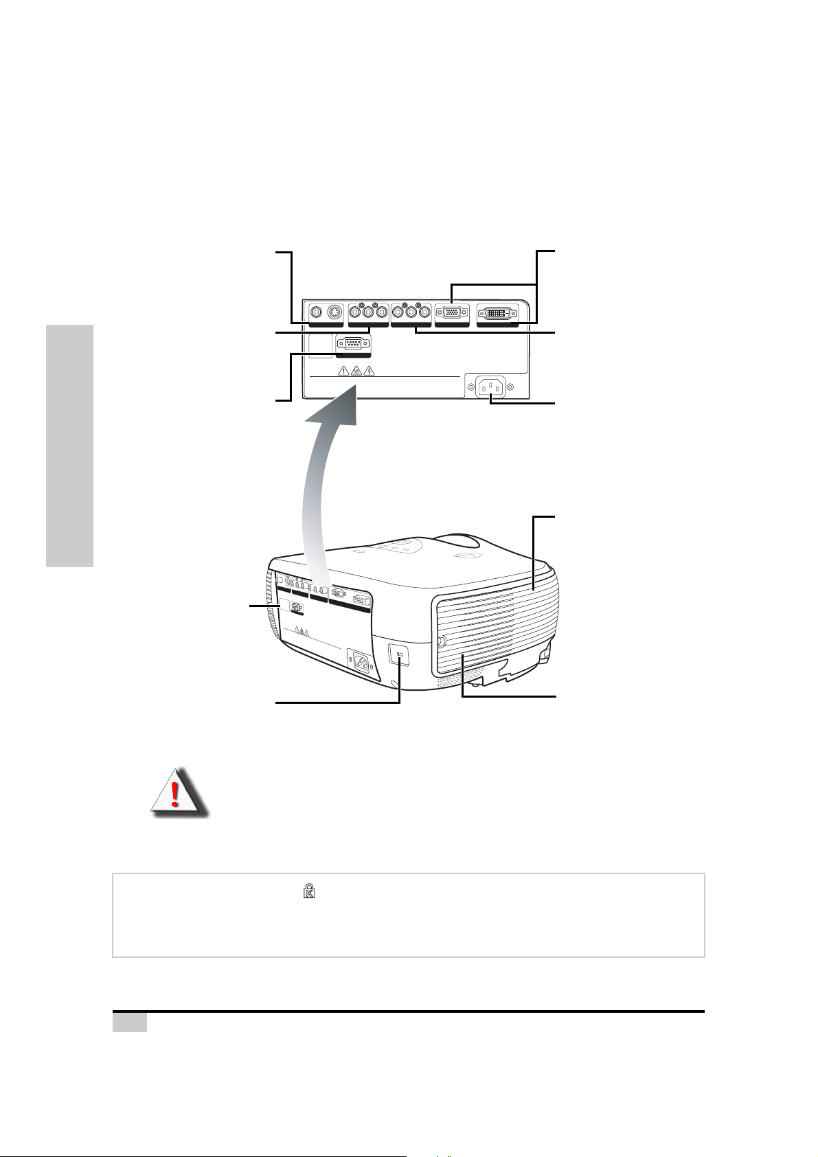
Projector (Rear View)
Terminal for connecting video
equipment with an S-video or
Composite Video terminal.
Terminals for component and
Introduction
Remote control sensor
Input 3
Video/S-Video
Input 1
Component 1
YPbPr/YCbCr.
RS-232C terminal
Firmware upgrade/
command control.
Pr/Cr Pb/Cb Y
S-VIDEOVIDEO
RS-232
WARNING
•
Do not disassemble any components except the lamp chassis cover while replacing the lamp.
•
Do not touch ventilation slots, lamp and objects next to them until they have sufficiently cooled down.
•
Never insert any objects through ventilation holes.
•
Do not use this unit near water or in a rainy/moist environment.
•
Keep at least 0.3 foot (10 cm) of space between ventilation slots and nearest object or wall.
V
ID
E
O
S
-V
ID
E
O
Pr/Cr
Pb/Cb
Y
Pr/Cr
Pb/Cb
Y
PC
cover while r
eplacing the lamp.
iciently cooled down.
DVI
Made in
Taiwan
RS-232
WARNING
•
Do not disassemble any components exc
•
Do not touch ventilation slots, lamp and objects next
•
Never insert any o
•
Do not use this uni
•
Keep at least 0.3 foot (10 cm) of space between ventilation slots and nearest object or wall.
bjects through ventilation holes.
ept the lamp chassis
t near water or in a rainy/moist environment.
to them until they have suff
Pr/Cr Pb/Cb Y
PC
Made in Taiwan
Input 4
DVI/PC
Terminal for Digital Video
Interface, computer and RGB
signals.
DVI
Input 2
Component 2
Terminals for component YPbPr
YCbCr.
AC socket
Input: 100~240VAC
3.5A,50/60Hz
Exhause vent
Kensington Security
Exhaust vent
Standard connector
WARNING! The projector lamp can reach high temperatures, making air blowing out from the
ventilation slots uncomfortably hot.
Using the Kensington Lock
This projector has a Kensington Security Standard connector for use with a Kensington MicroSaver
Security System. Refer to the information that came with the system for instructions on how to use it to
secure the projector.
10
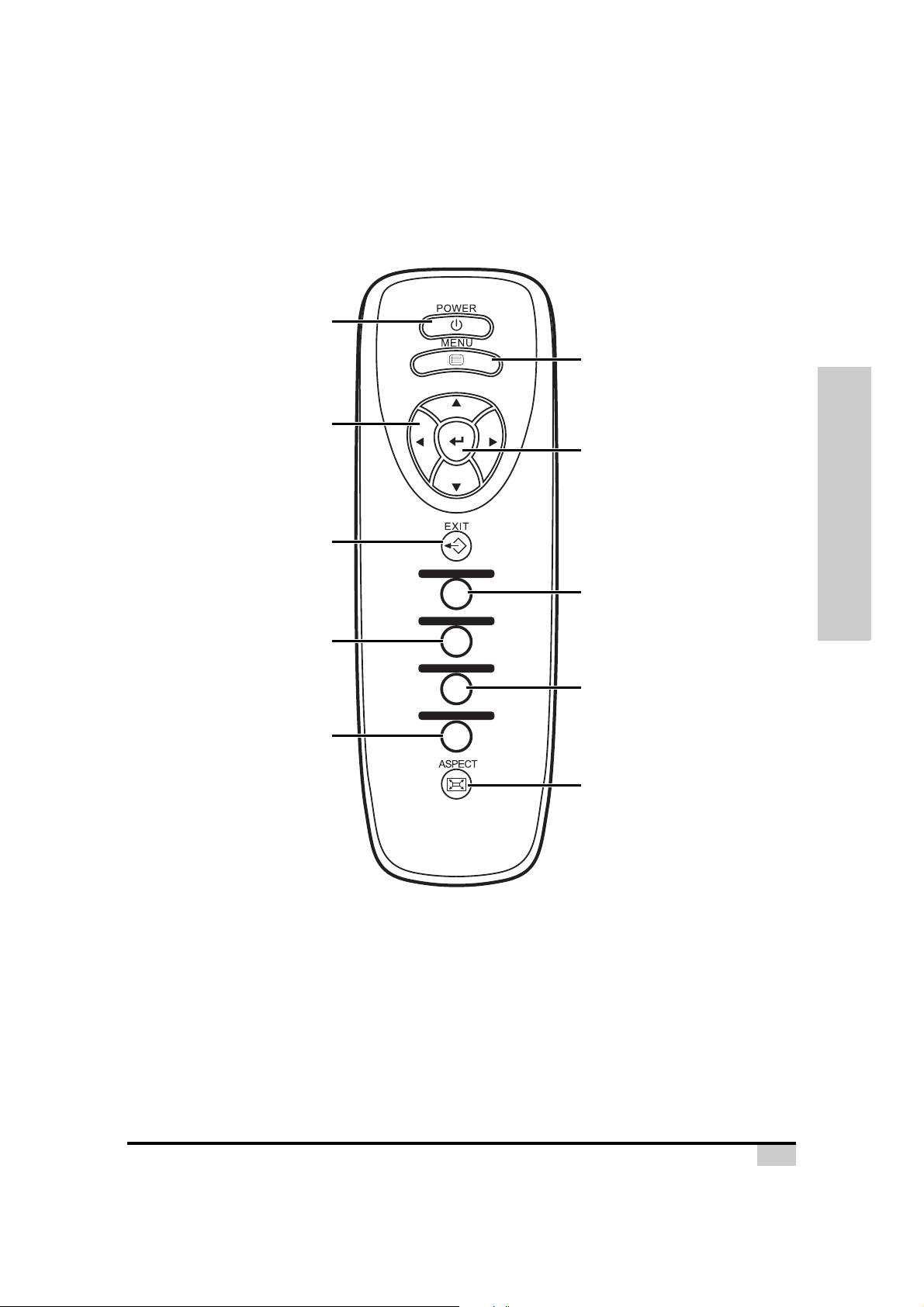
Remote Control
Power (ON/OFF) button
Press to turn the power on and off.
MENU button
Press to open the OSD
menus.
Adjustment buttons
Press to display adjustment
Component 2 button
Press to connect to component
Press to connect a Digital
Video Interface device or
computer's VGA source.
(T,S,W,X)
and setting screens.
EXIT button
Press to exit the OSD.
device sources.
DVI/PC button
COMPONENT 1
COMPONENT 2
VIDEO/S-VIDEO
DVI/PC
ENTER button
Press to set selected items or
adjustments in the menu.
Component 1 button
Press to connect to component device
sources.
VIDEO/S-VIDEO button
Press to connect to a standard RCA
video or S-video source.
Aspect Ratio button
Controls how the projector resizes the
input image.
Introduction
11
Using the Remote Control
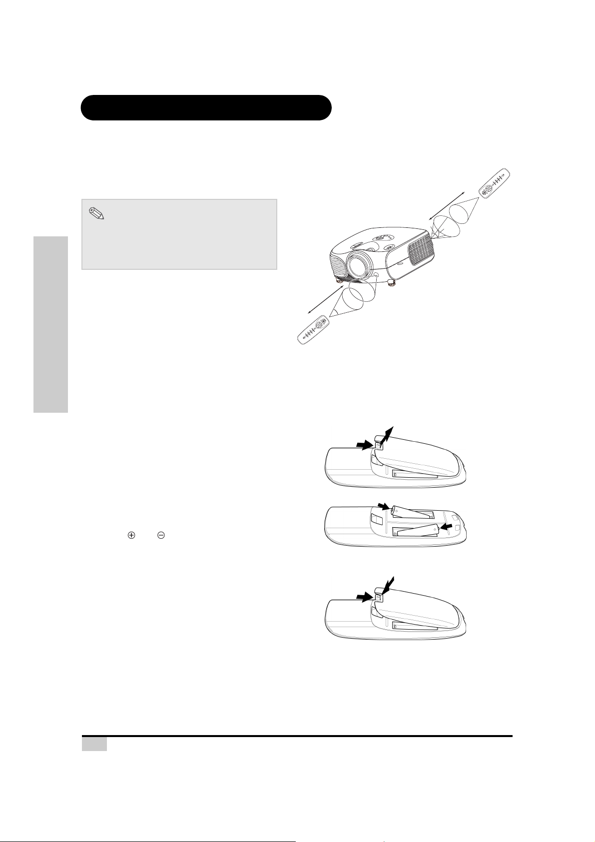
Available Range of the Remote Control
The remote control can be used to control the
projector within the ranges shown in the
illustration.
Note
• The signal from the remote control can be
reflected by the screen. You can control
the projector when it is behind you by
bouncing the signal off the screen.
When using the remote control:
• Do not drop it, or expose it to moisture or high
temperature.
• The remote control may not function correctly
under fluorescent lamps. Operate the projector
away from fluorescent lamps.
Introduction
Inserting the Batteries
The batteries (two AAA) are included in the package.
Press down the tab on the cover
1
and pull the cover towards the
direction of the arrow.
23'(7 m)
C
O
M
P
O
N
C
E
O
N
M
T
P
1
O
N
V
E
ID
N
T
E
O
2
/
S
-
V
I
D
E
D
O
V
I
/P
C
30°
45°
23'(7 m)
45°
30°
30°
C
P
/
I
V
D
O
E
D
I
V
S
/
O
2
E
T
D
I
N
V
E
N
O
P
1
M
T
O
N
C
E
N
O
P
M
O
C
Insert the included batteries.
2
Make sure the polarities correctly match
the and marks inside the battery
compartment.
Insert the lower tab of the cover
3
into the opening, and press down
the cover until it clicks in place.
12

Connections and Setup
Connections and Setup
13
Connecting the Projector to Other Devices
Before Setting Up
Note
• Before connecting, turn off both the projector and the devices to be connected. After making all
connections, turn on the projector first and then the other devices.
When connecting a computer, be sure that the computer is the last device turned on, after all
connections are made.
• Read the operation manuals of the devices to be connected before making connections.
This projector can be connected to
Video equipment:
A VCR, Laser disc player or other video equipment.
A DVD player or DTV* decoder.
*DTV is the umbrella term used to describe the new digital television system.
A computer, using:
A HD 15-pin VGA to HD 15-pin VGA cable (sold separately), or
A DVI-D to DVI-D cable (sold separately), or
An RS-232C cable (sold separately).
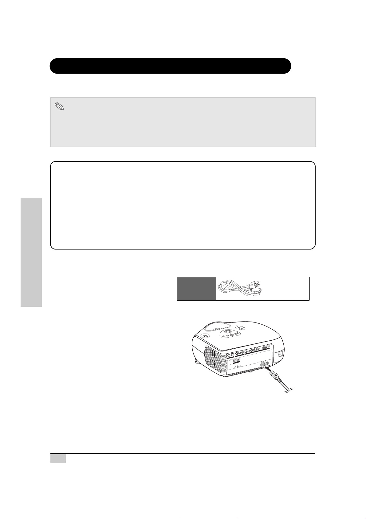
Connecting the Power Cord
Connections and Setup
Plug the supplied power cord into the AC
socket on the rear of the projector.
14
Supplied
accessory
Y
b
/C
b
P
r
r/C
P
O
E
ID
V
-
S
O
E
D
I
V
2
3
-2
S
R
ion holes.
ilat
WARNING
hrough vent
etween ventilation slots and nearest ob
s t
Do not disassemble any components except the lamp chassis cove
•
r water or in a rainy/moist environment.
any object
Do not touch ventilation slots, lamp and objects next to them until they have s
•
is unit nea
Never insert
•
Do not use th
•
Keep at least 0.3 foot (10 cm) of space b
•
Power cord
I
DV
PC
Y
b
/C
b
P
r
/C
Pr
wan
Made in Tai
.
ufficiently cooled down.
r while replacing the lamp
ject or wall.

Connecting to Video Equipment
S-VIDEO
VIDEO
Pr/Cr
Pb/Cb
Y
Pr/Cr
Pb/Cb
Y
PC
WARNING
•
Do not disassemble any components except the lam
p chassis cover while repl
acing the lamp.
•
Do not touch ventilatio
n slots, lamp and objects next to them until they have sufficiently cooled down.
•
Never insert any objects through ventilation holes.
•
Do not use this unit near water or in a rai
ny/moist envi
ronment.
•
Keep at least 0.3 foot
(10 cm) of space between
ventilation slots and n
earest object or wall.
Made in
Tai
wan
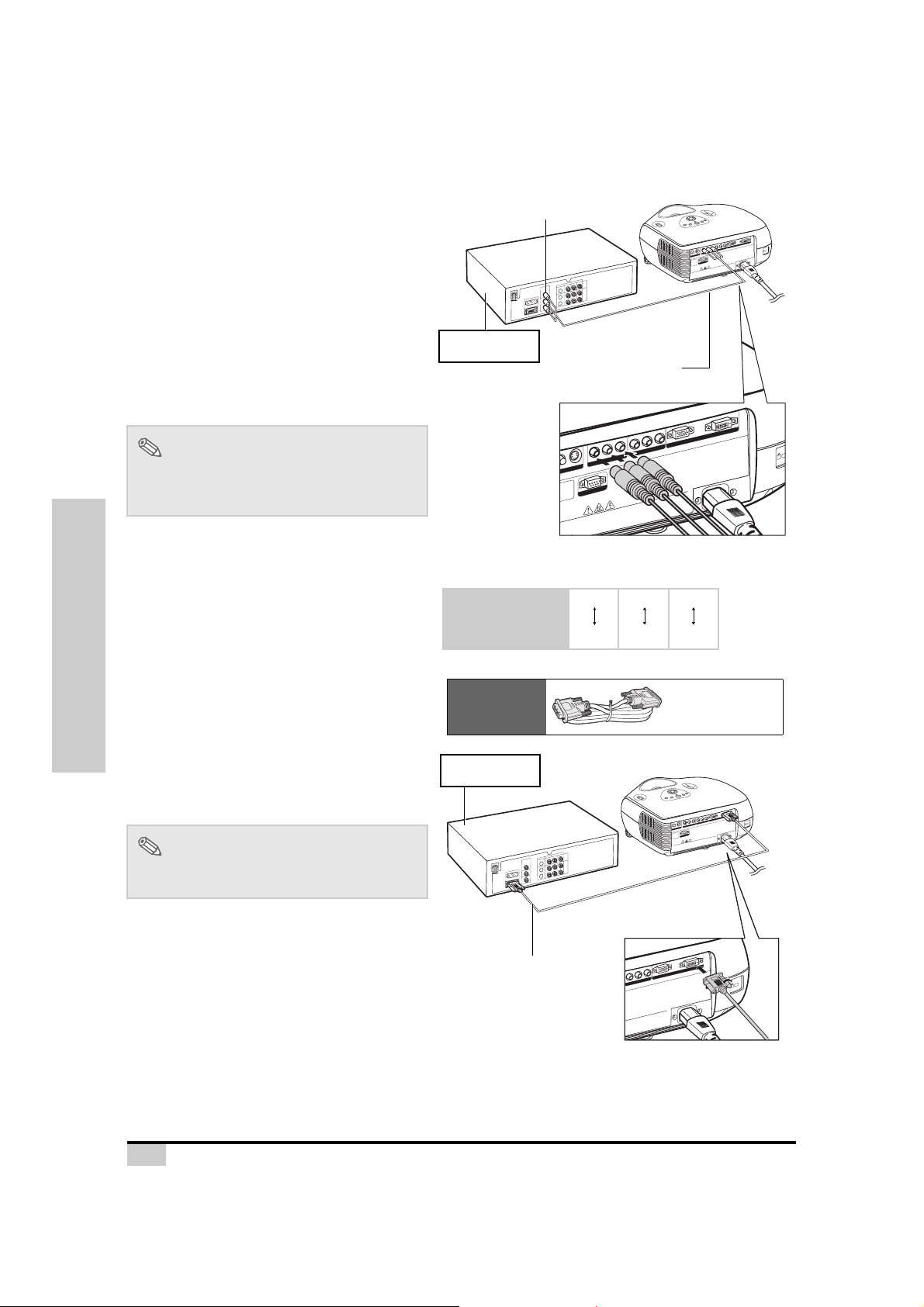
Using an S-video or a Composite Video
Cable (INPUT 3)
Using an S-video or a composite video cable,
a VCR, laser disc player or other video
equipment can be connected to the INPUT 3
terminals.
Notes
• The INPUT 3 (S-VIDEO) terminal uses a
video signal system in which the picture is
separated into color and luminance signals
to give a higher-quality image. To view the
higher-quality image, use a commercially
available S-video cable to connect the
INPUT 3 terminal on the projector and the
S-video output terminal on the video
equipment.
VCR or other video equipment
To S-video output terminal
To Video output terminal
Composite video cable
(sold separately)
S-video cable (sold
separately)
VI
D
C
P
Y
b
C
/
b
P
r
C
/
r
P
Y
b
C
/
b
P
r
C
/
r
P
O
E
ID
V
-
S
O
E
D
I
V
2
n
3
a
2
-
w
i
S
a
R
T
in
e
d
a
M
.
p
m
.
la
n
w
e
o
h
t
d
g
d
n
e
i
l
c
o
a
o
l
c
p
e
y
r
l
t
e
n
l
i
e
i
h
c
i
w
f
f
r
u
e
s
v
o
e
c
v
a
s
i
h
s
y
s
e
a
h
h
t
c
il
p
t
n
m
u
a
l
m
e
e
h
t
h
t
t
.
l
p
o
l
t
e
a
t
c
w
x
x
r
e
e
o
n
s
t
t
s
c
G
t
n
c
e
je
e
n
j
b
o
IN
b
o
p
o
t
N
s
m
d
.
e
o
t
.
n
r
c
n
s
R
a
a
e
e
y
l
e
p
n
m
A
o
n
a
m
n
h
d
o
la
e
n
r
n
W
l
i
,
o
a
b
v
i
s
t
n
t
s
m
t
e
o
la
e
l
i
o
t
t
l
s
s
s
s
n
s
i
n
e
a
o
n
v
s
io
o
i
m
t
i
/
h
d
t
a
y
g
a
t
il
l
n
t
i
u
o
i
t
n
o
n
a
n
r
e
r
e
h
o
v
t
v
a
D
h
s
n
n
t
c
i
•
e
c
u
r
e
e
o
j
o
t
w
b
t
r
t
o
e
e
o
t
b
n
y
a
n
e
o
w
a
c
D
r
t
a
r
a
p
•
e
e
s
s
n
f
t
in
o
i
r
n
)
e
u
m
v
c
s
e
i
h
0
N
t
1
(
•
e
t
s
o
u
o
t
f
o
3
n
.
0
o
t
D
s
a
•
le
t
a
p
e
e
K
•
Connections and Setup
-232
S
R
15
Connecting to Component
R
S-2
32
S
-V
ID
E
O
E
O
Pr/Cr
Pb/Cb
Y
Pr/Cr
Pb/Cb
Y
PC
DVI
W
A
R
N
IN
G
•
Do not disassemble any components except the lamp chassis cover while replacing the lamp.
•
Do not touch ventilation slots, lamp and objects next to them until they have suff
iciently cooled down.
•
Never insert any objects through ventilation holes.
foot (10 cm) of
space between venti
lati
on slots and nearest object or
wall.
Made in Taiwan
Pr/Cr
Pb/Cb
Y
P
C
D
V
I
chassis
cover w
hile replacing the lam
p.
to the
m
until they h
ave suff
iciently cooled down.
vironm
ent.
ilatio
n slots and nearest object or w
all.
M
ade in Taiwan
Video Equipment
Using a Component Cable (INPUT 1 or 2)
Use a component cable when connecting
component video equipment such as DVD
players and DTV* decoders to the INPUT 1 or
2 terminals.
*DTV is an umbrella term used to describe the
new digital television system.
Note
• When connecting the projector to video
equipment in this way, set “Input Source” to
“Component 1 or 2” in the “Main” menu.
To analog component
output terminal
I
V
D
C
P
Y
b
C
/
b
P
r
C
/
r
P
Y
b
C
/
b
P
r
C
/
r
P
O
E
D
I
-V
S
O
E
D
I
V
n
a
2
w
i
3
a
2
-
T
S
R
n
i
e
d
a
M
.
p
m
.
a
n
l
w
e
o
h
d
t
d
g
n
le
i
c
o
a
o
l
c
p
y
e
l
r
t
n
le
e
i
i
h
c
i
f
w
f
r
u
e
s
v
e
o
v
c
a
s
h
i
s
y
s
e
a
h
h
t
c
l
i
t
p
n
m
u
a
l
m
e
e
.
h
l
h
t
l
t
a
t
p
to
w
e
t
r
c
x
o
x
e
t
e
n
c
s
e
s
t
j
t
n
b
c
e
o
je
n
t
b
o
s
o
p
e
.
t
r
d
.
m
n
a
s
n
o
e
e
a
e
c
n
l
m
ING
o
y
p
n
d
h
n
o
m
n
r
a
N
i
a
a
n
l
v
o
e
s
i
l
,
n
t
t
s
b
e
o
t
a
l
l
t
m
i
o
AR
s
l
t
s
e
i
s
n
s
n
o
e
s
o
n
W
i
v
a
m
o
t
/
i
s
t
h
i
y
la
i
a
g
d
l
t
in
i
u
t
n
t
a
o
o
r
e
n
r
n
v
e
h
a
t
v
o
n
n
s
h
i
e
t
D
c
e
r
c
•
u
o
w
je
t
o
r
t
b
e
e
t
o
b
t
o
a
y
e
n
n
c
w
o
a
a
r
p
t
D
a
r
s
e
e
•
f
n
s
o
n
it
i
)
n
r
m
u
e
c
v
s
i
0
e
h
1
t
(
N
e
t
•
s
o
u
o
f
t
o
3
.
n
0
o
t
s
D
a
•
e
l
t
a
p
e
e
K
•
DVD player or
DTV* decoder
Component cable
(sold separately)
The device’s component jacks may be labeled Y, CB and
CR. Connect each jack as shown below.
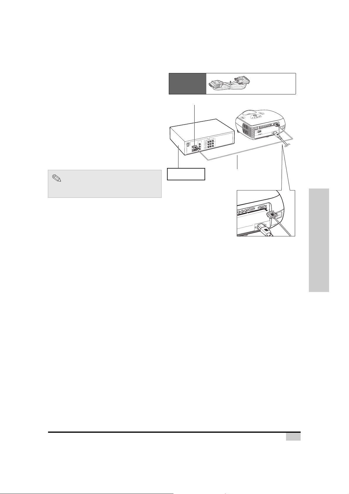
Connecting Using the DVI
Cable
Use the DVI cable when connecting video
Connections and Setup
equipment with DVI output such as DVD
players and DTV* decoders to the INPUT 4
terminal.
Note
• Select the input signal type of the video
equipment.
Projector Y
DVD player or
DTV decoder
Optional
accessory
DVD player or
DTV* decoder
DVI-D cable
(sold separately)
PB
Y
CB
PR
CR
DVI-D cable
I
DV
PC
Y
b
C
/
b
P
r
C
/
r
P
Y
b
C
/
b
P
r
C
/
r
P
O
E
D
I
V
S
O
E
D
I
V
2
n
3
a
2
-
w
i
S
a
R
T
n
i
e
d
a
M
.
p
m
.
a
l
n
w
e
o
h
t
d
g
d
n
e
i
l
c
o
a
o
l
c
p
e
y
r
l
t
e
n
l
i
e
i
h
c
i
w
f
f
r
u
e
s
v
o
e
c
v
a
s
i
h
s
y
s
e
a
h
h
t
c
l
i
p
t
n
m
u
a
l
m
e
e
h
t
h
t
t
l.
p
o
l
t
e
a
t
c
w
x
x
r
e
e
o
n
s
t
t
s
c
G
t
n
c
e
je
e
n
b
j
IN
o
o
b
p
o
t
N
s
m
d
.
e
o
t
.
n
r
c
n
s
R
a
a
e
e
y
l
e
p
n
A
m
o
n
a
m
n
h
d
a
o
l
e
n
n
r
W
l
i
,
o
a
b
v
i
s
t
n
t
s
m
a
t
e
o
l
e
l
i
o
l
t
t
s
s
s
s
n
s
i
n
e
a
o
n
o
v
s
i
o
i
m
t
/
d
h
ti
a
y
l
g
a
t
i
n
t
il
u
o
i
t
n
o
n
a
n
r
e
r
e
h
o
v
t
v
a
D
h
s
n
n
t
c
i
•
e
c
u
r
e
e
o
j
o
t
w
b
t
r
t
o
e
e
o
t
b
n
y
a
n
e
o
w
a
c
D
r
t
a
r
a
p
•
e
e
s
s
n
f
n
t
i
o
i
r
n
)
e
u
m
v
c
s
e
i
h
0
N
t
1
(
•
e
t
s
o
u
o
t
f
o
3
n
.
0
o
t
D
s
a
•
e
l
t
a
p
e
e
K
•
16
Connecting Using a DVI-D to
Pr/Cr
Pb/Cb
Y
P
C
D
VI
p chassis
cover while replacing the lam
p.
t to th
e
m
until they have suff
iciently cooled d
ow
n.
nvironm
ent.
tilatio
n slots and neare
st object or w
all.
M
ade in
T
ai
w
an
HDMI Cable
Use a DVI to HDMI cable when connecting
HDMI video equipment such as DVD players
to the INPUT 4 terminal.
Connect a DVI-D to HDMI cable to
1
the projector.
• Secure the connectors by tightening
the thumbscrews.
Connect the above cable to the
2
video equipment.
Optional
accessory
To HDMI output terminal
DVI-D to HDMI
cable
I
V
D
PC
Y
b
C
/
b
P
r
C
/
r
P
Y
b
C
/
b
P
r
C
/
r
P
O
E
D
I
V
S
O
E
D
I
V
2
n
3
a
2
-
w
i
S
a
R
T
n
i
e
d
a
M
.
p
m
.
a
l
n
w
e
o
h
t
d
g
d
n
i
le
c
o
a
o
l
c
p
e
y
r
l
t
n
le
i
e
i
h
c
i
w
f
f
r
u
e
s
v
o
e
c
v
a
s
i
h
s
y
s
e
a
h
h
t
c
il
p
t
n
m
u
la
m
e
e
h
t
h
t
t
.
l
p
l
o
t
e
a
t
c
w
x
x
r
e
e
o
n
s
t
t
s
c
G
t
n
c
e
je
e
n
N
b
j
o
I
o
b
p
o
t
N
s
m
d
.
e
o
t
.
n
r
c
n
s
R
a
a
e
e
y
l
e
p
n
A
m
o
n
a
m
n
h
d
a
o
l
e
n
n
r
W
l
i
,
o
a
b
v
i
s
t
n
t
s
m
t
e
o
la
e
l
i
lo
t
t
s
s
s
s
n
s
i
n
e
a
o
n
o
v
s
i
i
m
t
io
/
d
t
h
a
y
l
a
g
t
i
n
t
il
u
o
i
t
n
o
n
a
n
r
e
r
e
h
o
v
t
v
a
D
h
s
n
n
t
c
i
•
e
c
u
r
e
o
je
o
t
w
b
t
r
t
o
e
e
o
t
b
n
y
a
n
e
o
w
a
c
D
r
t
a
r
a
p
•
e
e
s
s
n
f
t
in
o
i
r
n
)
e
u
m
v
c
e
is
h
0
N
t
1
(
•
e
t
s
o
u
o
t
f
o
3
n
.
0
o
t
D
s
a
•
e
l
t
a
p
e
e
K
•
Note
• Select the input signal type of the video
equipment.
DVD player or
DTV* decoder
DVI-D to HDMI cable
(sold separately)
Connections and Setup
17
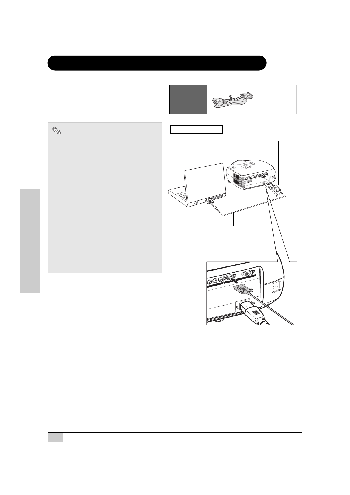
Connecting the Projector to a Computer
Pr/Cr
Pb/Cb
Y
PC
DVI
chassis cover while
replacing the
la
m
p
.
to
them
until t
hey have suff
iciently coole
d do
w
n.
viro
n
m
e
n
t.
il
ation slots a
nd
n
ea
re
st o
bje
ct o
r w
all.
M
ade in
T
ai
w
an
Connect the projector to the computer
using an HD 15-pin VGA cable.
• Secure the cable connectors by tightening
the screws on both sides of the plug.
Optional
accessory
HD 15-pin
VGA cable
Notes
• See page 60 “Computer Compatibility
Chart” for a list of computer signals
compatible with the projector. Using
computer signals other than those listed
may cause some of the functions not to
work.
• When connecting the projector to a
computer using an HD 15-pin VGA cable,
set the “Input Source” to “PC” in the “Main”
menu, or select RGB mode by pressing the
DVI/PC button on the remote control.
• A Macintosh adaptor may be required for
use with some Macintosh computers.
Contact your nearest authorized service
center or dealer.
• Depending on the computer you are using,
an image may not be projected unless the
signal output setting of the computer is
switched to the external output. Refer to the
computer operation manual for switching
the computer signal output settings.
Connections and Setup
Notebook Computer
To VGA output terminal
HD 15-pin VGA cable
(sold separately)
C
P
Y
b
C
b/
P
r
r/C
P
Y
b
/C
b
P
r
C
r/
P
O
E
ID
-V
S
O
E
ID
V
n
wa
RS-232
ai
T
de in
a
M
.
p
m
n.
w
e la
do
ed
ing th
ol
lac
p
co
tly
e re
n
il
icie
r wh
uff
e
v
s
ve
is co
ha
y
ss
e
ha
c
p
til th
n
lam
m u
e
e
th
th
ept
all.
t to
x
w
exc
ne
s
t or
t
c
G
ts
n
ne
N
I
obje
bjec
t
o
s
N
mpo
t.
nd
re
s.
R
a
en
a
y co
le
n
o
A
ne
nm
mp
d
a
n
W
le a
iro
v
b
tion h
n
ts, l
ts a
o
la
em
ti
sl
st e
n
ss
slo
oi
n
ve
/m
tio
ation
l
t disa
ila
iny
nti
ough
nt
no
e
ve
a ra
v
Do
ch
•
en
cts thr
r in
e
j
o
b
r
t tou
o
etwe
e
t
b
a
ny
o no
ce
t a
D
ar w
pa
•
er
e
t n
i
of s
)
er ins
cm
ev
is un
10
th
N
•
se
u
t
foot (
o
3
.
o n
st 0
D
•
ep at lea
e
K
•
HD 15-pin VGA cable
(commercially available)
I
V
D
18
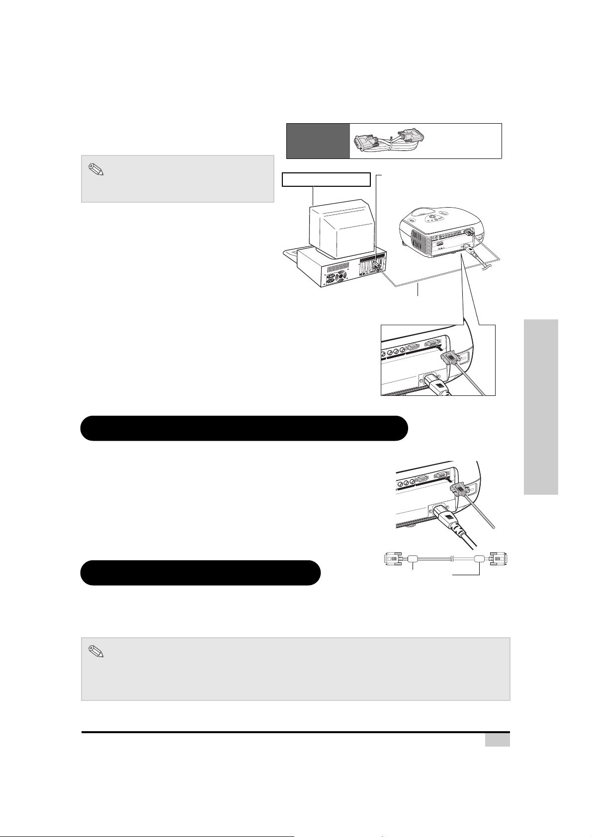
Connect the projector to the computer
Y
P
r/C
r
P
b
/C
b
Y
PC
DVI
the lam
p c
hassis co
ver w
hile
rep
lacing
the lam
p.
e
cts n
ext to
th
em
until they have suff
iciently cooled dow
n.
h
oles
.
m
oist environm
en
t.
een
ve
ntila
tio
n slots an
d ne
arest object or w
all.
M
ade in
T
aiw
an
using a DVI-D cable (sold separately).
Optional
accessory
DVI-D cable
Note
• Select the input signal type of the video
equipment.
Connecting the Cables
Desktop Computer
To DVI Digital output terminal
I
DV
PC
Y
b
C
/
b
P
r
C
/
r
P
Y
b
C
/
b
P
r
/C
r
P
O
E
D
I
V
S
O
E
D
I
V
2
n
3
a
2
-
w
i
S
a
R
T
in
e
d
a
M
.
p
m
.
a
l
n
w
e
o
h
t
d
g
d
n
i
le
c
o
a
o
l
c
p
e
y
r
l
t
n
le
i
e
i
h
c
i
w
f
f
r
u
e
s
v
o
e
c
v
a
s
i
h
s
y
s
e
a
h
h
t
c
l
i
p
t
n
m
u
a
l
m
e
e
h
t
h
t
t
.
p
o
ll
t
e
a
t
c
w
x
x
r
e
e
o
n
s
t
t
s
c
G
t
n
c
e
e
j
n
je
b
o
IN
b
o
p
o
t
s
N
m
d
.
e
o
t
.
n
r
c
n
s
R
a
a
e
y
le
e
p
n
m
A
o
n
a
m
n
h
d
a
o
l
e
n
r
n
W
l
i
,
o
a
b
v
i
s
t
n
t
s
m
a
t
e
l
e
lo
i
o
t
t
l
s
s
s
s
n
s
i
n
e
a
o
n
o
v
s
i
o
i
m
t
i
/
h
d
t
a
y
l
g
a
t
i
l
n
t
i
u
o
i
t
n
o
n
a
n
r
r
e
e
h
o
v
t
v
a
D
h
s
n
t
c
in
•
e
c
u
r
e
e
o
j
o
t
w
b
t
r
t
o
e
e
o
t
b
n
y
a
n
e
o
w
a
c
D
r
t
a
r
a
p
•
e
e
s
s
n
f
n
i
o
it
r
n
)
e
u
m
v
c
s
e
i
h
0
N
t
1
(
•
e
t
s
o
u
o
t
f
o
3
n
.
0
o
t
D
s
a
•
e
l
t
a
p
e
e
K
•
DVI-D cable
(sold separately)
Connections and Setup
Connect the cable making sure that it fits correctly into the terminal.
Secure the connectors by tightening the screws on both sides of the
plug.
Do not remove the ferrite cores attached to the cable.
“Plug and Play” Function
Y
b
C
/
b
P
r
/C
r
P
p
e
r
ile
h
r w
e
v
s
o
e
v
c
a
is
s
h
s
y
a
e
h
h
c
p
til t
n
u
m
e
h
t
o
t t
t
s
.
e
t
r
n
a
e
e
m
n
n
d
o
n
ir
v
a
n
ts
lo
s
n
io
t
tila
n
Ferrite cores
VI
D
PC
n
a
w
i
a
T
in
e
d
a
M
.
p
m
.
la
n
w
e
o
th
d
g
d
in
le
c
o
la
o
c
y
tl
n
e
i
c
i
f
f
u
ll.
a
w
r
o
t
c
je
b
o
This projector is compatible with VESA-standard DDC 1/DDC 2B. The projector and a VESA DDC
compatible computer automatically send settings, allowing for quick and easy setup.
Before using the “Plug and Play” function, be sure to turn on the projector first and the computer last.
Note
• The DDC “Plug and Play” function of this projector operates only when used in conjunction with a VESA
DDC compatible computer.
19
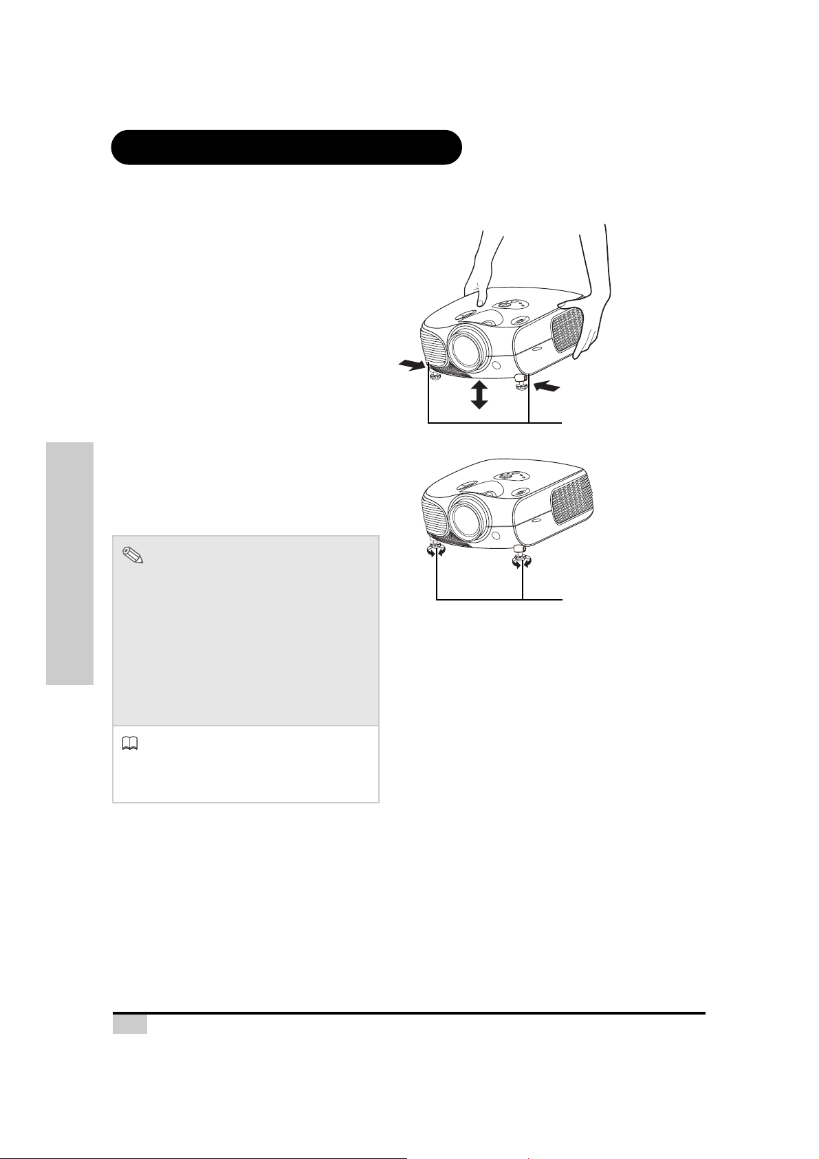
Using the Adjustment Feet
Use the adjustment feet to level the projector
when it is placed on an uneven surface or
when the screen is slanted.
The projection can be made higher by
adjusting the projector when it is in a location
lower than the screen.
Press the foot releases and lift
1
the projector to the desired
angle.
Remove your hands from the foot
2
releases. When the adjustment
feet have locked in position,
place the projector down.
• If the screen is at an angle, the
adjustment feet can be used to adjust
the angle of the image.
Foot releases
Notes
• The projector is adjustable up to
approximately 11 degrees from the standard
position.
• When the height of the projector is adjusted,
the image may become distorted
Connections and Setup
(keystoned), depending on the relative
positions of the projector and the screen.
See page 44 for details on keystone
correction.
Info
• When lowering the projector, be careful not
to catch your fingers in the area between
the adjustment foot and the projector.
Adjustment feet
20
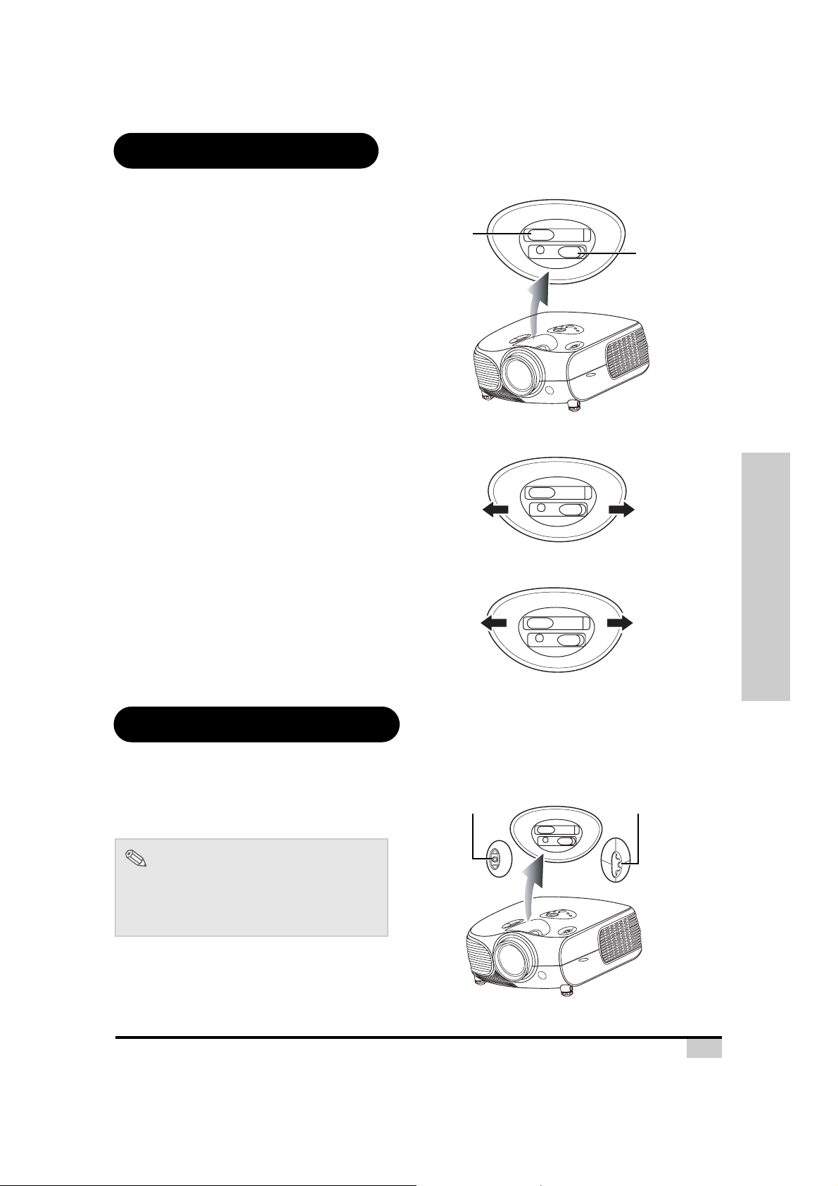
Adjusting the Lens
Adjust the lens using the focus and zoom
rings to correct the image.
Focus ring
Focus
Zoom
Zoom ring
Adjust zoom by rotating the zoom
1
ring.
Adjust focus by moving the focus
2
ring.
Using the Lens Shift
The height and width of the projected image
can be adjusted to be within the shift range of
the lens by rotating the lens shift dial at the top
of the projector.
Zoom ring
t
u
m
o
o
o
Z
Focus ring
Lens shift dial
(Vertical)
i
n
m
o
o
Z
Lens shift dial
(Horizontal)
Connections and Setup
Note
• Do not forcibly turn the lens shift dial beyond
the range of the upper left and lower right
positions. This may cause the projector to
malfunction.
21
 Loading...