

Page 1

Copyright © 1998 by Boxlight Corporation.
Poulsbo, Washington. All rights reserved.
Page 2

FCC Warning
This equipment has been tested and found to comply with the limits for a Class A
digital device, pursuant to part 15 of the FCC Rules. These limits are designed to
provide reasonable protection against harmful interference when the equipment
is operated in a commercial environment. This equipment generates, uses, and
can radiate radio frequency energy and, if not installed and used in accordance
with the instruction manual, may cause harmful interference to radio communications. Operation of this equipment in a residential area is likely to cause harmful interference in which case the user will be required to correct the interference
at his own expense.
DOC (Canada)
This Class A digital apparatus meets all requirements of the Canadian Interference-Causing Equipment Regulations.
Cet appareil numerique de la classe A respecte toutes les exigences du Reglement
sur le materiel brouilleur du Canada.
Safety Certifications
UL, CUL, TÜV, NOM
EN 55022 Warning
This product is intended for use in a commercial, industrial, or educational environment. It is not intended for residential use.
This is a Class A product. In a domestic environment it may cause radio interference, in which case the user may be required to take adequate measures. The typical use is in a conference room, meeting room or auditorium.
Wenn das Produkt Boxlight 9000 in Deutschland verkauft wird, muss es Umwelt
geschuetzt sein. (Klasse B) Dieses Product muss mit dem Bundesamt fuer Post
und Telekommunikation registriert sein. (BAPT)
Trademarks
Apple, Macintosh, and PowerBook are trademarks or registered trademarks of
Apple Computer, Inc. IBM and PS/2 are trademarks or registered trademarks of
International Business Machines, Inc. MicroSaver and Kensington are trademarks
or registered trademarks of Kensington Microware Limited. Microsoft, PowerPoint, and Windows are trademarks or registered trademarks of Microsoft Corporation. CablePro is a trademark or registered trademark of Boxlight Corporation.
Page 3

Declaration of Conformity
Manufacturer: Boxlight Corporation
19332 Powder Hill Place, Poulsbo, Washington USA
We declare under our sole responsibility that the Boxlight 9000 Projector conforms
to the following directives and norms:
Directive 89/336/EEC, Amended by 93/68/EEC
EMI: EN 55022 (1992) Class A
EMC: EN 50082-1 (1992)
IEC 801-2, IEC 801-3, IEC 801-4
Directive 73/23/EEC, Amended by 93/68/EEC
Safety: EN 60950: 1992 + A1 + A2 + A3: 1995
March, 1998
Page 4

Page 5

TABLE OF CONTENTS
Safety Summary iii
Introduction 1
Image Resolution 1
Compatibility 1
Unpacking the Projector 1
Usage Guidelines 4
If You Need Assistance 4
Warranty 4
Setting up the Projector 5
Connecting an IBM-Compatible Computer Using the CablePro
Lite Cable 11
Connecting a Macintosh Computer Using the CablePro Lite
Cable 12
Connecting a Computer Using a VESA cable 13
Connecting a Computer using BNC cables 13
Connecting a Video Player 14
Connecting an External Speaker 15
Connecting the Remote Control Cable 16
Connecting a Computer with an RS-232 Cable 16
Powering up the Projector and Adjusting the Image 16
Turning Off the Projector 17
Using the Projector 19
Basic Image Adjustment 19
Adjusting the Projector 20
Using the Remote Control 21
Using the Remote and Keypad Buttons 22
Using the On-Screen Menus 25
Display Menu Functions 27
Audio Menu Functions 29
Image Menu Functions 31
Controls Menu Functions 33
i
Page 6

Ta b l e o f C o n t e n t s
Maintenance and Troubleshooting 35
Cleaning the Lens 35
Cleaning the Fan Intake Filter 35
Replacing the Projection Lamp 37
Replacing the Batteries in the Remote Control 39
Using the Kensington Lock 39
Troubleshooting 40
Solutions to Common Problems 40
Appendix 45
Specifications 45
Accessories 47
Portable and Laptop Activation Chart 49
Using Video Mirroring with a PowerBook Computer 53
Projected Image Size for Optional Lenses 54
Connection Pin Assignments 55
RS232 Terminal Specifications 57
Index 61
ii
Page 7
SAFETY SUMMARY
Please read these instructions carefully before using your projector. Failure to comply with them could result in fire, electrical
shock, personal injury or damage to equipment.
These graphics are used throughout this manual to draw your
attention to important information about the projectors.
NOTE: Additional useful details or tips.
CAUTION: Steps to take to avoid damage to your equipment.
WARNING: Steps to take to avoid personal injury.
These graphics are used on the projector’s labels.
Attention
- Refer to this User’s Guide for important
safety information.
CAUTION: Hot Surfaces
- Avoid touching hot surfaces.
Do not touch until the projector has cooled.
Do Not Look Into The Lens!
Be extremely careful not to look into the projection lens when the
projector is turned on. The bright light may harm your eyes. Be
especially careful to keep children from looking into the lens.
Pow e r S o urce
Use only a three-wire grounding type power source. The power
source should not exceed 270 Volts RMS between the supply conductors or between either conductor and earth ground.
Power Cord
Use only the power cord that was shipped with the projector.
Although other power cords might be similar in appearance, they
have not been safety-tested with the projector. Do not use a
power cord if it has become damaged or frayed. Contact Boxlight
at 1-800-762-5757 if you need to replace your power cord.
iii
Page 8

Safety Summary
Grounding
The projector is grounded through the grounding conductor on
the power cord. To avoid electric shock, plug the power cord into
a properly wired receptacle. Do not defeat the purpose of the
grounding-type plug.
Lamp
To avoid overheating and unacceptable image quality, replace the
projection lamp with a lamp of the specified type. Refer to
page 45 for lamp specifications and to page 37 for instructions on
replacing the lamp.
Lamp Compartment
To avoid burns, do not open the lamp module door until the projector is turned off and the lamp has cooled for at least 30 minutes. Follow the instructions in this manual for lamp replacement
carefully.
Hot Surfaces
Allow the projector to cool at least 30 minutes before replacing a
lamp. When you open the lamp housing, be very careful not to
touch the hot surfaces inside.
NOTE: If you open the projector
case, you will void the warranty.
iv
Ventilation and Overheating
Openings in the projector case provide ventilation to protect it
from overheating. Keep loose papers and other objects well away
from the grills. Do not place the projector on top of or close to a
computer or other heat-producing equipment.
Liquid Spills
Do not set drinks on top of the projector. Spilled liquids can flow
inside and cause damage.
Do Not Disassemble
All service must be performed by Boxlight. The only user-serviceable parts in the projector are the projection lamp, which you can
replace by opening the lamp cover on the side of the projector
(see page 37) and the fan intake filter (see page 35). Do not open
any other part of the projector.
Page 9

INTRODUCTION
The Boxlight 9000 is an XGA multimedia projector designed for
fixed installations. It allows 3 computer and 2 video inputs, along
with RS-232 control.
Image Resolution
The Boxlight 9000 can display VGA, SVGA, XGA, and SXGA
images. The native resolution of the projected image is XGA
1024x768. Screen resolutions between 1024x768 and 1280x1024
are compressed to 1024x768. The projector cannot compress
screen resolutions above 1280x1024. If your computer’s screen
resolution is higher than 1280x1024, reset it to a lower resolution
before you connect the projector
.
Compatibility
The projector is compatible with a wide variety of computers and
video devices, including:
•
IBM-compatible computers, including laptops, up to 1280x1024
resolution at 75 Hz.
•
Apple Macintosh and PowerBook computers up to 1280x1024
resolution.
•
Selected workstations (contact Boxlight for details).
•
Most standard VCRs, camcorders, DVD and laser disc players.
Unpacking the Projector
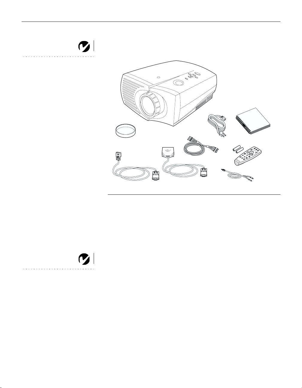
The projector comes with the items shown in Figure 1. Check to
make sure all are included. Contact Boxlight immediately if anything is missing.
NOTE: The projector automati-
cally expands 640x480 and
800x600 images to fill the screen.
You can display these images at
their original resolutions by turn-
ing off the Auto Resize feature.
See “Auto Resize” on page 31 for
more information.
NOTE: The projector is compati-
ble with many third-party control-
lers and amplifiers, including
AMX, Crestron, and Extron. Call
Boxlight for details.
If you are experienced in setting up presentation systems, use the
Boxlight 9000 Quick Start
card that was included in the shipping
box. For complete details on connecting and operating the projector, refer to this User’s Guide.
NOTE: For model 9000-INT: To
use video input, an optional video
board must be installed in the pro-
jector. Contact Boxlight for more
information.
1
Page 10
Introduction
NOTE: For model 9000-INT: To
use video input, an optional video
board must be installed in the
projector. Contact Boxlight for
more information.
1
2
3
9
5
4
NOTE: Long throw and short
throw lenses are also available.
See “Optional Accessories” on
page 47.
8
7
6
F
IGURE 1
Shipping box contents
1. Boxlight 9000 projector 6. computer audio cable
2. Boxlight 9000 User’s Guide 7. CablePro Lite computer cable
3. power cord 8. VESA computer cable
4. remote and batteries 9. lens cap
5. VCR cable (RCA A/V cable)
Not shown: Quick Start card
2
Page 11
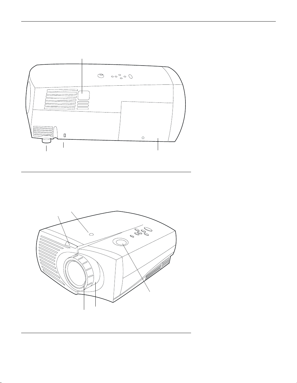
power cord
connector
leveling
foot
Ken sin gton Loc k
remote control
receivers
focus ring
lamp compartment
FIGURE 2
Side view of projector
lens shift knob
zoom ring
IGURE
F
Front view of projector
3
3
Page 12

Introduction
Usage Guidelines
•
Do not look directly into the projection lens when the projector
is turned on. The bright light may harm your eyes.
•
Do not block the grills on the projector. Do not place the projector on cloth table coverings, as they may get sucked up to the
vents. Restricting the air flow can cause the projector to overheat and turn off.
•
Handle the projector as you would any product with glass
components. Be especially careful not to drop it.
•
Avoid leaving the projector in direct sunlight or extreme cold
for extended periods of time. If this happens, allow it to reach
room temperature before use.
•
This projector is not intended for use in mainframe computer
rooms as defined in the Standard for the Protection of Electronic Computer/Data Processing Equipment, ANSI/NFPA 75.
•
Transport the projector in a vendor-approved hard or soft case.
Call Boxlight to order.
If You Need Assistance
The first place to look for help is in this manual. Be sure to check
the guidelines in “Troubleshooting” on page 40.
If this manual doesn’t answer your question, call Boxlight at
1-800-762-5757
.
Warranty
This product is backed by a limited one-year warranty. The
details of the warranty are printed at the back of this manual.
4
Page 13

SETTING UP THE PROJECTOR
Place the projector on a flat surface.
1
•
The projector must be within 7.5 feet (2.3 m) of your power
source.
•
If you are installing the projector on the ceiling, refer to the
Ceiling Mount Installation Guide
that comes with the Ceiling
Mount Kit for more information. To turn the image upside
down, see “Ceiling” on page 34. The Ceiling Mount Kit is
sold separately; see page 48.
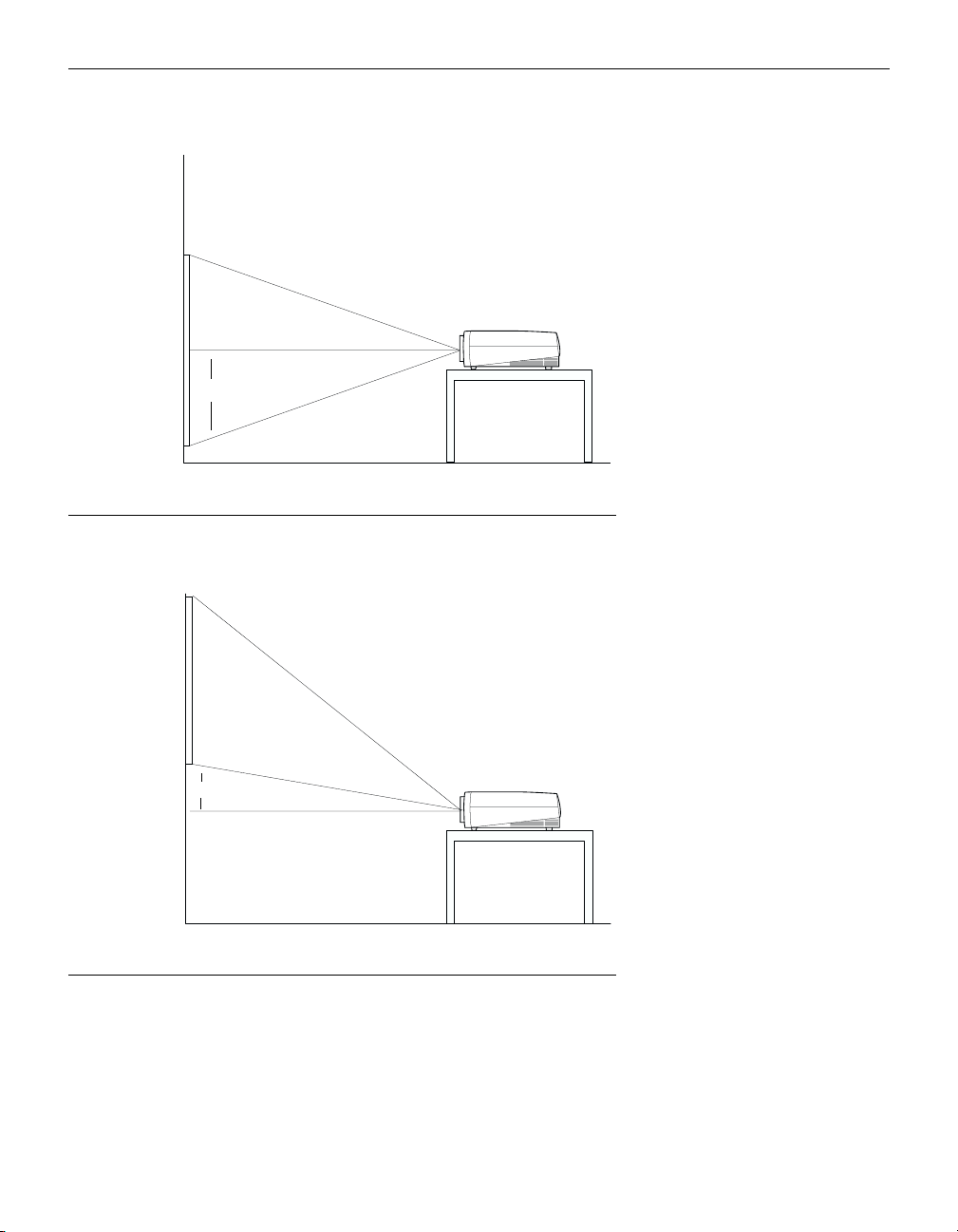
Position the projector the desired distance from the screen.
2
•
The distance from the lens of the projector to the screen and
the zoom lens setting determine the size of the projected
image. Table 1 shows example projected image sizes and
minimum and maximum distances to the screen.
The formulas for distance to the screen are:
Max distance (ft) = diagonal image size (ft) ÷ .541
Min distance (ft) = diagonal image size (ft) ÷ .716
Ta b l e 1:
Diagonal Image Size and Width at Maximum and Minimum Distance
to Screen-Zoom Lens
Distance to screen
Diagonal
Image Size
(inches)
300 240 46.3 35.0
240 192 37 28.0
180 144 27.8 21
144 115 22.2 16.8
120 96 18.5 14
96 77 14.8 11.2
72 58 11.1 8.4
60 48 9.3 7
48 38 7.4 5.6
Image Width
(inches)
Maximum
distance
(feet)
Minimum
Distance
(feet)
NOTE: For a similar table for the
optional long throw and short
throw lenses, see page 54 of the
Appendix.
5
Page 14
Setting up the Projector
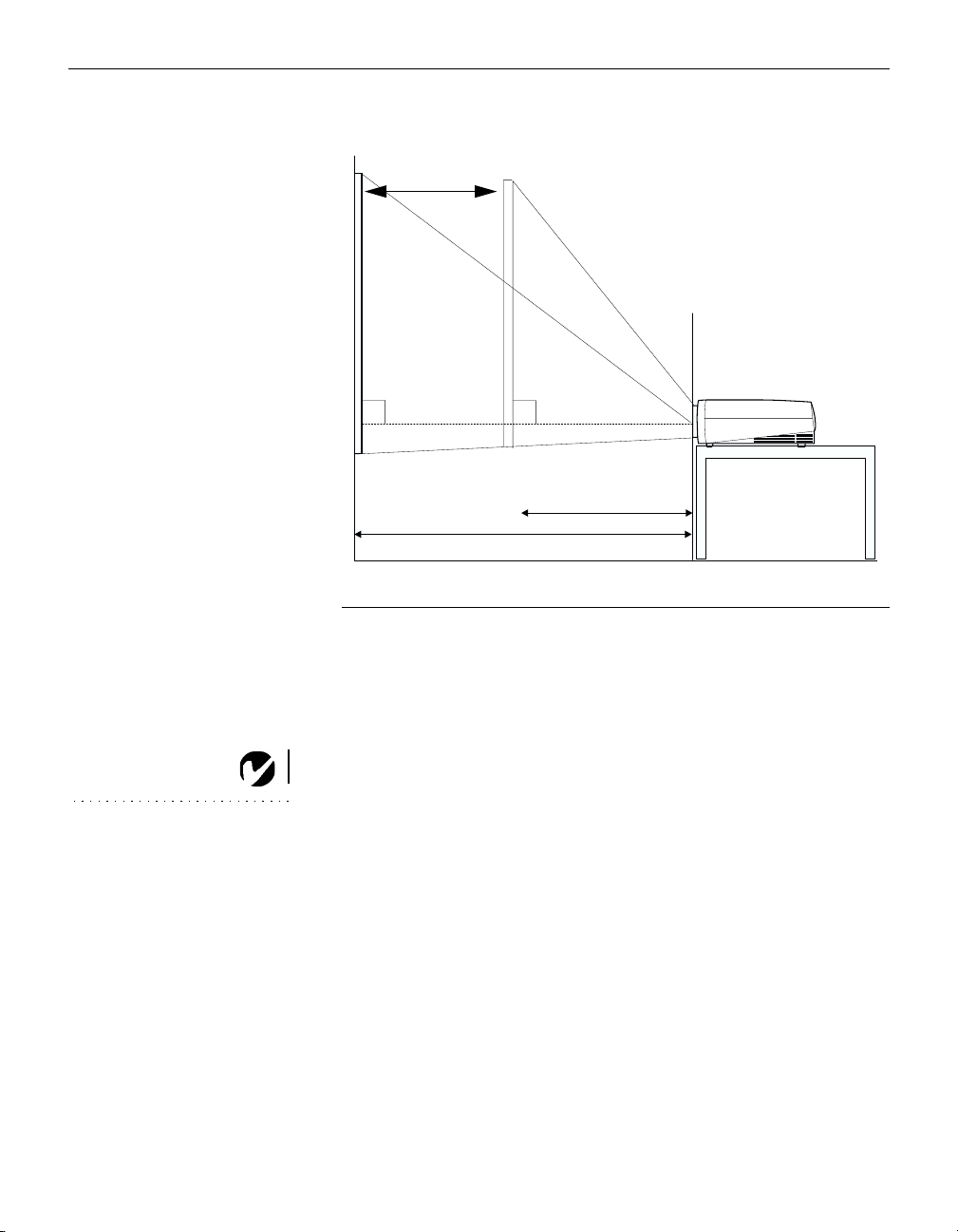
zoom adjustment range:
18.5-14’
NOTE: The lens shift is not
adjustable on the optional short
throw lens. It is fixed at zero
degrees.
90º
maximum L: 18.5’
distance between lens and screen: L
IGURE 4
F
Projected image size for 10’ diagonal image size
90º
minimum L: 14’
The projector is equipped with a lens shift feature that allows you
to adjust the projection height (move the image along the wall)
without moving the projector, while still maintaining a perfectly
square image. Turn the lens shift knob on top of the projector to
make this adjustment (see Figure 3 on page 3).
The bottom of the image can move from half way below the projector’s lens (Figure 5) to 25% above the lens (Figure 6).
Example:
With a 10’ image, at the lowest projection angle, the bottom of the image is 5’ below the projector’s lens; at the highest
projection angle, the bottom of the image is 2.5’ above the lens.
6
Page 15
10’ high
image
bottom of image
5’ below lens
10’ high
image
bottom of image
2.5’ above lens
lens center
H
FIGURE 5
Lowest image projection angle
H
lens center
F
IGURE
Highest image projection angle
Once you know the diagonal image size, you can figure out the
width and height using these formulas:
width (inches) = diagonal (inches) x 0.8
height (inches) = width (inches) x 0.75
6
7
Page 16

Setting up the Projector
The following tables give the lens shift values for desktop and
ceiling-mounted setups for various image sizes. The lower lens
shift position represents the highest the projector can be above
the bottom of the screen; the upper lens shift position represents
the lowest the projector can be below the bottom of the screen.
Ta b l e 2:
Lens Shift Positions for Desktop Setup
Distance from lens center to
lower edge of screen (H)
Diagonal
Image Size
(inches)
300 -89.7 46.6
240 -71.7 37.2
180 -53.8 27.9
144 -43.0 22.3
120 -35.9 18.6
96 -28.7 14.9
72 -21.5 11.2
60 -17.9 9.3
48 -14.3 7.4
Lower lens
shift position
(inches)
Upper lens
shift position
(inches)
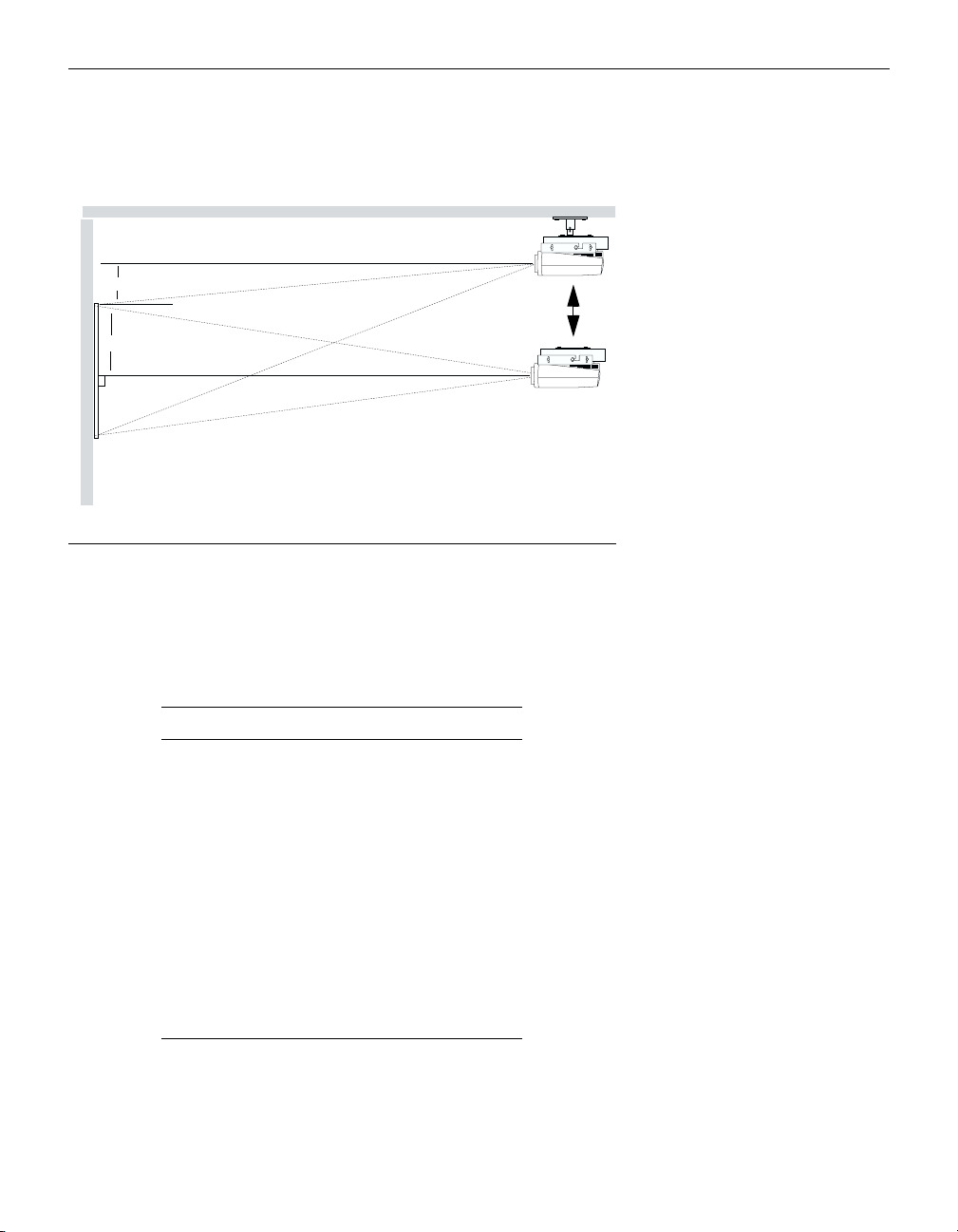
When the projector is ceiling mounted, use the upper edge of the
screen as the base line.
Ta b l e 3:
Lens Shift Positions for Ceiling-Mounted Setup
Distance from lens center to
upper edge of screen (H)
Diagonal
Image Size
(inches)
300 89.7 -46.6
240 71.7 -37.2
180 53.8 -27.9
144 43.0 -22.3
120 35.9 -18.6
96 28.7 -14.9
72 21.5 -11.2
60 17.9 -9.3
48 14.3 -7.4
Lower lens
shift position
(inches)
Upper lens
shift position
(inches)
8
Page 17
lens center
H
high edge of screen
H
lens center
FIGURE 7
Lens shift with ceiling-mounted projector
Now you’re ready to connect your equipment.
Steps for connecting the different types of equipment are given
on the pages listed below.
Equipment you want to connect Page
IBM-compatible computer with
page 11
CablePro Lite
Macintosh computer with CablePro
page 12
Lite
Computer with VESA cable page 13
Computer with BNC cables page 13
Video player page 14
External speaker page 15
Remote cable page 16
RS-232 cable page 16
9
Page 18
Setting up the Projector
2
NOTE: For model 9000-INT: To
use video input, an optional video
board must be installed in the
projector. Contact Boxlight for
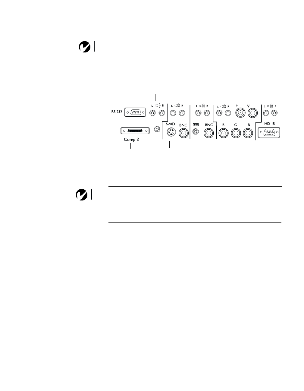
Computer 3
external
speaker
Video 1
Video 2
more information.
Computer 1
Computer
NOTE: For the connection pin
assignments, see page 55.
CablePro
F
IGURE 8
wired remote
s-video
composite
video-RCA
5 BNCs
Connector panel
The projector has the following audio/video inputs:
Source Video Audio
Computer 1 3 Single-ended analog RGB
+ 2 H&V sync (5 BNCs)
Computer 2 VESA Single-ended analog
RGB (HD-15)*
Computer 3 CablePro Analog RGB*
Video 1 S-video Y/C (4-pin circular)ORLeft and right line-level
Base-band composite video
(BNC)
Video 2 Base-band composite video
(RCA)* OR
Left and right line-level
(2 RCAs)*
Left and right line-level
(2 RCAs)*
(2 RCAs)*
Left and right line-level
(2 RCAs)*
HD 15
VESA
10
Base-band composite video
(BNC)
*indicates cable included with projector
Page 19
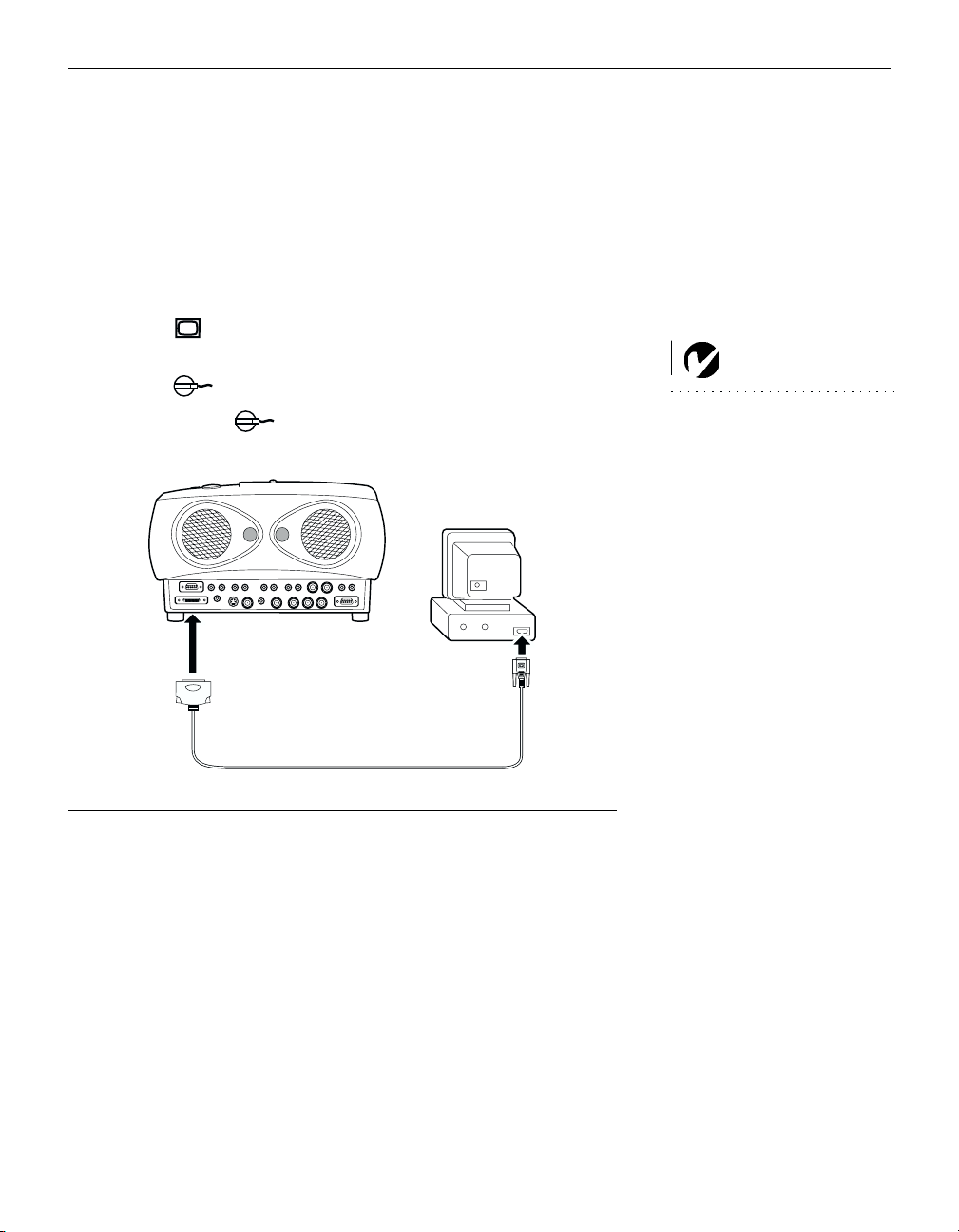
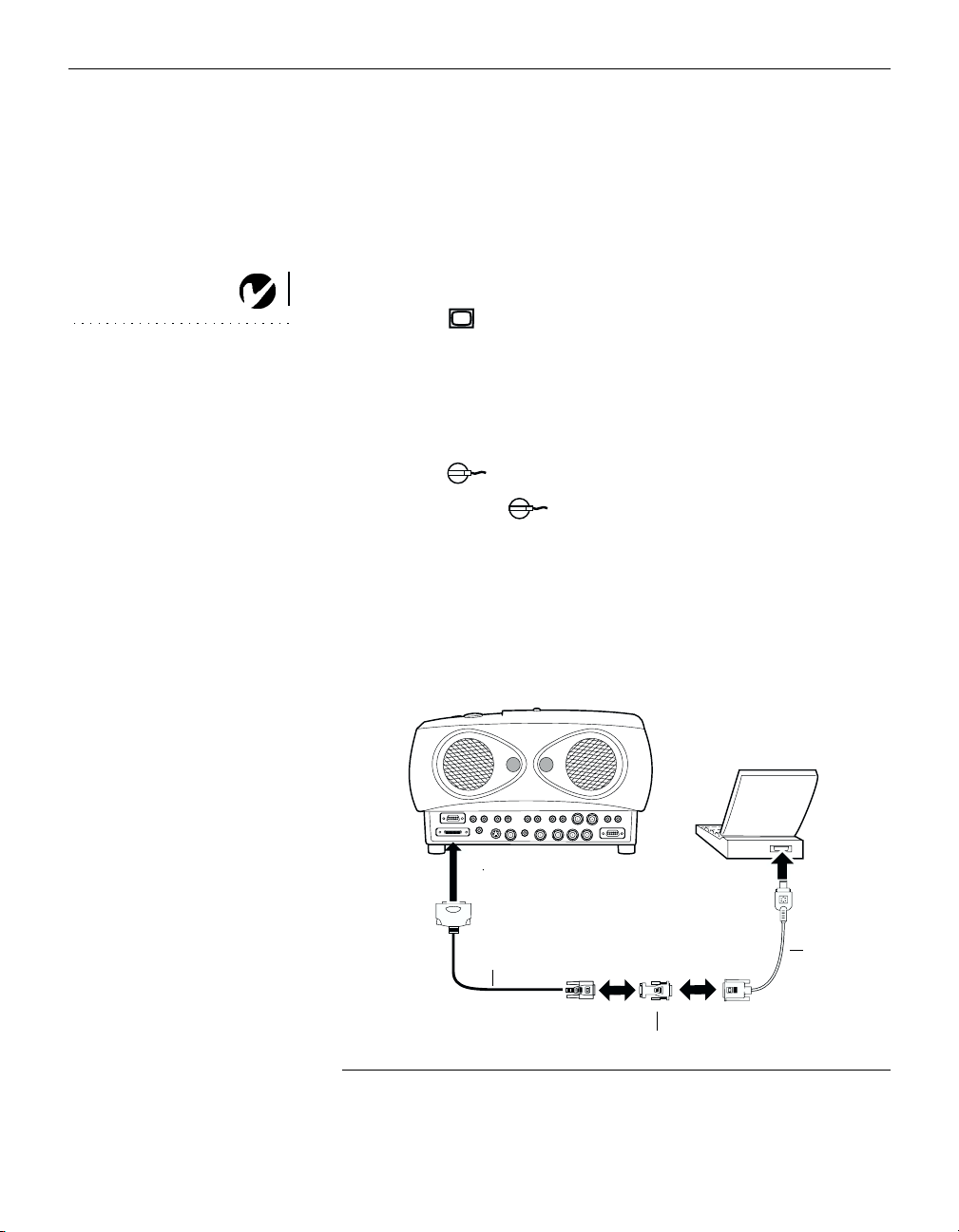
Connecting an IBM-Compatible Computer Using the
CablePro Lite Cable
The CablePro Lite cable provides a computer connection. If you
want audio, mouse control, or monitor loop-through, purchase
the optional CablePro. See “Optional Accessories” on page 47.
This input is designated Computer 3.
Plug the end of the CablePro Lite computer cable into the
1
video connector on your computer.
Plug the end of the CablePro Lite computer cable into
2
the Computer 3 connector on the projector.
audio cable
CablePro Lite cable
NOTE: Many laptop computers
do not automatically turn on their
external video port when a sec-
ondary display device such as a
projector is connected. Refer to
your computer manual for the
command that activates the exter-
nal video port. Activation com-
mands for some laptop computers
are listed in the Appendix of this
manual on page 49.
FIGURE 9
Connecting the CablePro Lite computer cable to an IBM-compatible computer
11
Page 20
Setting up the Projector
Connecting a Macintosh Computer Using the CablePro Lite
Cable
The CablePro Lite cable provides a computer connection. If you
want audio, mouse control, or monitor loop-through, purchase
the optional CablePro. See “Optional Accessories” on page 47.
This input is designated Computer 3.
Plug the end of the CablePro Lite computer cable into the
1
NOTE: Some PowerBooks require
the Apple-supplied video-out cable
or monitor adapter for external
video. Connect it between the
PowerBook and the CablePro Lite
computer cable/Mac adaptor as
shown in Figure 10.
Boxlight Macintosh adaptor (sold separately).
Plug the CablePro Lite/Mac adaptor into the video connector
2
on your computer (or the Apple video-out cable or monitor
adapter, if needed).
Plug the end of the CablePro Lite computer cable into
3
the Computer 3 connector on the projector.
If you want the projector display to be the same as the Power-
4
Book’s screen display, turn on video mirroring (called
SimulScan in newer PowerBooks). See “Using Video Mirroring with a PowerBook Computer” on page 53 for additional
information.
12
CablePro Lite cable
Mac adaptor
F
10
IGURE
Connecting the CablePro Lite computer cable to a Macintosh
PowerBook
video-out cable
or monitor
adaptor
Page 21
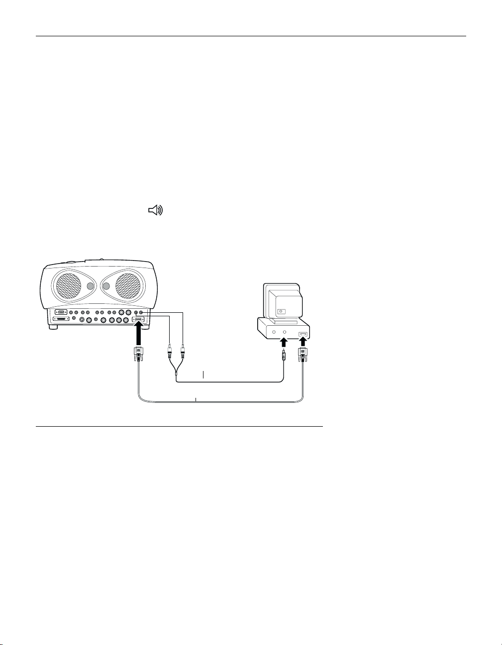
Connecting a Computer Using a VESA cable
The supplied VESA cable connects to the High Density 15-pin
connector (HD 15) on the projector. This input is designated
Computer 2.
Plug one end of the VESA cable into the video connector on
1
your computer. Plug the other end into the HD 15 connector
on the projector.
If you want audio with your presentation, plug the supplied
2
audio cable into the audio connector on your computer. Plug
the other end into the connectors on the projector above
the HD 15 connector.
audio cable
VESA cable
F
11
IGURE
Connecting the a computer with the VESA cable
Connecting a Computer using BNC cables
This input is designated Computer 1.
Connect the BNC cables to the appropriate connectors on the projector (Figure 8 on page 10) and on your computer. See “Connection Pin Assignments” on page 55 for more information.
13
Page 22
Setting up the Projector
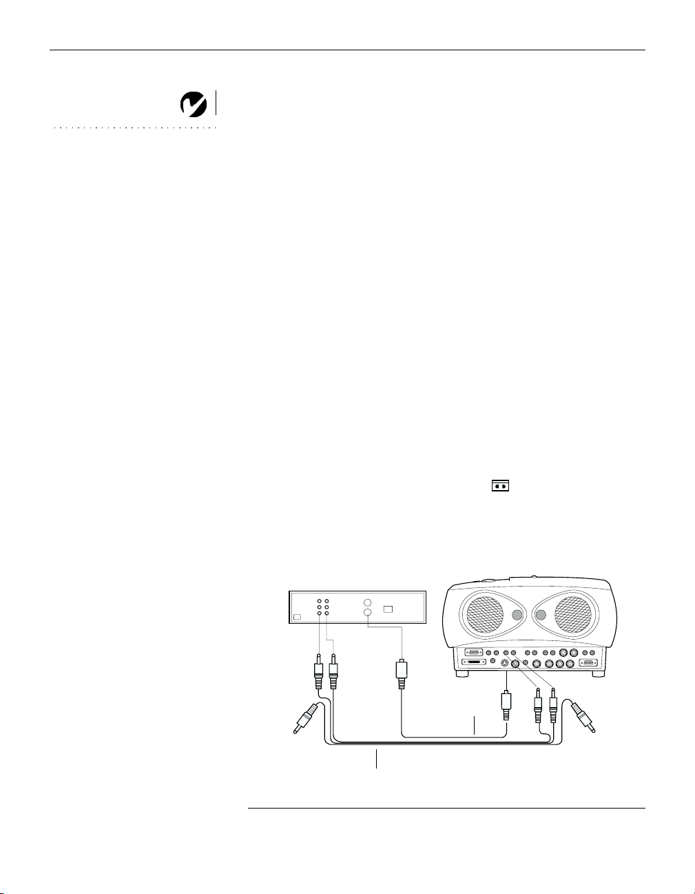
Connecting a Video Player
If your video player uses a round, one-prong composite video
1
NOTE: For model 9000-INT: To
use video input, an optional video
board must be installed in the
projector. Contact Boxlight for
more information.
connector, you’ll need only the A/V cable that shipped with
the projector. (Refer to Figure 14 on page 16 to see the connector types.)
•
If your video player uses a round, four-prong S-video connector, you’ll need an S-video cable in addition to the A/V
cable. If your video player uses a BNC connector, you’ll
need a BNC cable in addition to the A/V cable. The cables
are sold separately. (See “Optional Accessories” on
page 47.)
Plug the A/V cable’s yellow connector into the “video-out”
2
port on your video player. This port may be labeled “To Monitor.”
•
If you’re using an S-video cable, connect it to the “s-video
out” connector on the video player. If you’re using a BNC
cable, connect it to the BNC connector on the video player
(Figure 12).
14
Plug the other yellow connector into the composite connector
3
on the back of the projector (labeled
•
If you’re using S-video or BNC, plug the other end of the
under Video 2).
cable into the “S-VID” or “BNC” connector on the projector
(Figure 12).
S-video cable
A/V cable
FIGURE 12
Connecting the projector to a video player using an S-video cable and the audio connectors on the standard A/V cable
Page 23
Plug the A/V cable’s white connector into the left “audio out”
4
port on your video player. Plug the cable’s red connector into
the right “audio out” port on the video player.
•
If you’re using an S-video or BNC cable, the yellow connectors on the A/V cable remain unused (Figure 12).
Plug the A/V cable’s other white and red connectors to the
5
left and right “audio in” ports on the projector directly above
your video connection.
The projector is compatible with the these major broadcast video
standards: NTSC, NTSC 4.43, PAL, PAL-M, PAL-N and SECAM.
It automatically adjusts to optimize its performance for the
incoming video. The input signals for SECAM, PAL-M, and
PAL-N video cannot be automatically detected, therefore they
must be chosen manually; see “Video Standard” on page 33.
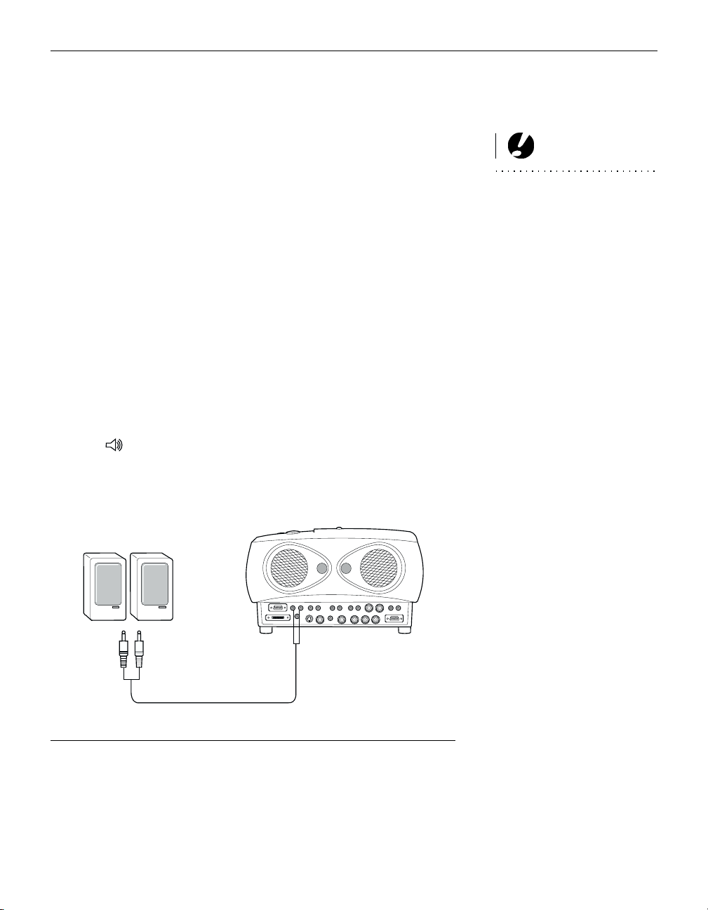
Connecting an External Speaker
To connect one or two external speakers, plug the speaker cable
into the (audio out) connectors on the projector. The external
speaker’s volume is controlled by the projector; see “Volume” on
page 25.
CAUTION: Your video player
may also have a “Video Out” port
for a coaxial cable connection.
DO NOT use this to connect to the
projector.
F
13
IGURE
Connecting external speakers
15
Page 24

Setting up the Projector
Connecting the Remote Control Cable
If the projector cannot receive the remote’s signal, as may be the
case if you’re using rear projection, connect the remote directly to
the projector with the remote cable.
Plug the remote cable into the connector on the projector.
1
NOTE: For more information on
using the remote, see page 21.
Plug the other end into the connector on the remote.
2
FIGURE 14
Connecting the remote control cable
NOTE: Always use the power cord
that shipped with the projector.
16
Connecting a Computer with an RS-232 Cable
You can control the projector from an LCD control panel by connecting an RS-232 cable to the projector (see Figure 8 on page 10).
See “RS232 Terminal Specifications” on page 57 for details.
Powering up the Projector and Adjusting the Image
Remove the lens cap.
1
Plug the power cord into the side of the projector, then plug it
2
into your electrical outlet. A surge-protected power strip is
recommended if power surges are common in your area.
Turn on the projector by pressing the power button on the
3
remote or keypad.
•
The startup screen displays.
Page 25

If you connected a video player, turn it on.
4
•
The image is displayed. If another source is active, press the
video 1 or video 2
button on the remote to display the image
from your video player, or press the Source button on the
keypad to cycle through the sources. (You can select a
default source to determine which source the projector
examines first during power-up for active video; see
“Default Source” on page 34.)
•
Use the
•
If you don’t want to hear the sound from your video player,
volume
press the
If you connected any external speakers, turn them on.
5
Turn on your computer.
6
•
The image is displayed. If another source is active, press the
computer 1, 2, or 3
buttons to adjust the volume.
button.
mute
button on the remote to display the
image from your computer, or press the Source button on
the keypad to cycle through the sources.
•
You can make adjustments to the image from the projector’s
on-screen menus. To open the menus, press the
menu
ton on the keypad or remote. Then select the Display menu
or the Image menu. For more information about the menus,
see page 25.
but-
NOTE: For model 9000-INT: To
use video input, an optional video
board must be installed in the pro-
jector. Contact Boxlight for more
information.
NOTE: With some computers,
the order in which you power up
the equipment is very important.
Most computers should be turned
on last, after all other peripherals
have been turned on. Refer to your
computer’s documentation to
determine the correct order.
•
If you don’t want to hear the sound from your computer,
press the
mute
button.
Turning Off the Projector
To turn the projector off, press the power button on the remote or
keypad. The lamp stays on for 15 seconds, then turns off. The fan
continues to run until the projector has cooled.
If you press power again within 15 seconds, the projector returns
to normal operation immediately.
CAUTION: When you discon-
nect the projector after you have
switched it off, always remove the
power cord from the electrical out-
let first, then remove it from the
projector.
17
Page 26

Page 27

USING THE PROJECTOR
This section describes how to use and make adjustments to the
projector. It also provides a reference to the remote and keypad
buttons and the options available from the on-screen menus.
Basic Image Adjustment
Make sure you have powered up your equipment in the right
1
order (page 16).
If the image doesn’t display completely, adjust the height and
2
tilt of the projector (page 20), zoom the image (page 20), or
center the image by adjusting its horizontal or vertical position (page 32).
If the image is out of focus, rotate the lens to focus it (page 20).
3
If the image appears to shimmer or if it has blurry vertical
4
bars after you have adjusted the focus, turn Auto Image
(page 31) off and then back on to reset the automatic sync and
tracking. If that doesn’t clear up the image, adjust the sync
(page 32) and/or the tracking (page 32) manually.
If the colors don’t look right, adjust the brightness, contrast,
5
and tint (page 27), and color and color temperature (page 28.)
19
Page 28

Using the Projector
Adjusting the Projector
To focus the image, rotate the focus ring (Figure 15) until the
image is clear. To zoom the image, rotate the zoom ring. This
adjusts the image size without affecting focus.
lens shift knob
focus ring
FIGURE 15
Focus ring and zoom ring
zoom ring
The projector is equipped with a projection angle lens shift knob
that provides 18 degrees of adjustment from horizontal. This
allows you to adjust the projection height without moving the
projector (see page 6 for lens shift values). It also has a heightadjustment foot and a leveling knob (Figure 17).
To adjust the height of the projector, lift the projector and move
the foot to the desired position. Rotate the leveling knob, if necessary, to adjust the angle of the projected image.
20
FIGURE 16
Adjusting the foot
Page 29

leveling knob
FIGURE 17
Leveling knob
Using the Remote Control
Point the remote control at the projection screen or at the projector. The range for optimum operation is about 30 feet. If you
point the remote at the projection screen, the distance to the
screen and back to the projector must be less than or equal to
30 feet. For best results, point the remote directly at the projector.
If you have purchased the optional CablePro and are creating
®
presentations in Microsoft
PowerPoint®, you can use the
remote’s mouse buttons to navigate through your presentation
while in Slide Show mode. To configure PowerPoint for this,
choose Options from the Tools menu, click the View Tab, de-select
the “Popup Menu on Right Mouse Click” option in the Slide
Show section, then click OK. Then, when you’re in PowerPoint’s
Slide Show mode, a left click advances to the next slide and a
right click returns to the previous slide (other PowerPoint modes
are not affected).
NOTE: If you can’t aim the
remote control at the projector so
that its signal is received
example, when using rear projec-
tion or in a large auditorium—
connect it directly to the projector
with the optional remote control
cable.
—
for
NOTE: If you want mouse control
of the Computer 3 input, purchase
the optional CablePro. If you want
mouse control of multiple sources,
purchase a third-party mouse.
21
Page 30

Using the Projector
Using the Remote and Keypad Buttons
This section provides an alphabetical reference to the remote and
NOTE: For model 9000-INT: To
use video input, an optional video
board must be installed in the
projector. Contact Boxlight for
more information.
keypad buttons.
22
FIGURE 18
Remote control
F
19
IGURE
Keypad
power button
mouse buttons
Page 31

Computer 1, 2 and 3
When you have more than one source (computer or video) connected to the projector, select between them by pressing the button for the source you want.
Press
computer 1, 2, or 3
to display your computer image or Lite-
Show Pro presentation.
Freeze
The
button halts, or “freezes” the projected image. Use this
freeze
button to freeze a frame of video (the video continues to run but
the projected image is frozen). You can also freeze an image from
a computer source on the screen, allowing you to perform other
operations on the computer without the audience seeing them.
Press
Help
again when you want the image to return to normal.
freeze
This displays the help information.
Light
Press
to illuminate the buttons on the remote control. The
light
light goes off automatically 10 seconds after you press any
button.
Menu
Press
to open the on-screen menus. Press
menu
menu
again to
close the menus. When you close the menus, the projector saves
any changes you made. For more information about the onscreen menus, see page 25.
NOTE: It takes a few seconds for
the projector to recognize a new
source. After the first time, the
source is recognized immediately.
NOTE: For model 9000-INT: To
use video input, an optional video
board must be installed in the pro-
jector. Contact Boxlight for more
information.
Mute
Pressing the
button silences the internal speakers. It also
mute
silences any external speakers that are connected.
To return the volume to its previous setting, press
press either
volume
button.
mute
again or
23
Page 32

Using the Projector
Scribble
The
scribble
button activates on-screen annotation.
Press the
1
Press the right disk mouse button (Figure 20 on page 25) to
2
scribble
button. The cursor changes to a pencil.
display the color selector. Use the disk mouse to position the
cursor on the desired color, then press the left mouse button.
Press the right button again to close the color selector.
Use the disk mouse to move the pencil to where you want to
3
start the annotation.
Press the left mouse button. The cursor changes to an upright
4
pencil.
Use the disk mouse to draw your annotation. Press the left
5
mouse button to complete the annotation.
To exit Scribble, press the
6
scribble
button. The annotation is
automatically deleted (it cannot be saved).
Pow e r
The Power button turns the projector on and off, and functions
the same on the keypad and remote. When you press power
while the projector is on, the lamp stays on for 15 seconds before
shutting off. If you press power again within 15 seconds, the projector returns to normal operation immediately. If you don’t press
power again, the lamp turns off after 15 seconds. The fan continues to run until the projector has cooled (approximately 30 seconds).
NOTE: For model 9000-INT: To
use video input, an optional video
board must be installed in the
projector. Contact Boxlight for
more information.
24
Video 1 and 2
When you have more than one source (computer or video) connected to the projector, select between them by pressing the button for the source you want.
Press
video 1 or 2
to display the image from your video player.
Page 33

Vol u m e
•
To increase the volume, press
•
To decrease the volume, press
Volume adjustments are saved for each source you have connected (including external speakers).
Using the On-Screen Menus
The projector
has four on-screen menus that allow you to make
image adjustments and change a variety of settings. Most of these
adjustments aren’t available directly from the keypad or remote.
To open the on-screen menus, press the
button on the key-
menu
pad or remote. This changes the volume, source, and mute buttons on the keypad to menu navigation buttons (and illuminates
the keypad green). Press the corresponding buttons to move the
cursor up, down, left, or right. To select a menu, use these buttons
to move the cursor to the tab for the menu you want, then click
either mouse button. To change a menu setting, move the cursor
to the setting you want to change using the navigation buttons,
then use one of the two mouse buttons to make changes. Press
again when you want to close the menus. All changes are
menu
saved when you close the menus.
To select a menu using the remote, use the disk mouse to move
the cursor to the tab for the menu you want, then click either
mouse button.
disk mouse
left mouse right mouse
button
button
NOTE: Some options in the
menus are only available when
certain equipment is connected.
For example, the Fade setting in
the Audio menu is only active if
external speakers are connected.
F
20
IGURE
Disk mouse and mouse buttons on remote
25
Page 34

Using the Projector
The status bar at the top of the menu display indicates the source
that is currently active (Computer or Video) and any peripherals
that are connected.
The status bar also contains a lamp hour counter that starts at
NOTE: For model 9000-INT: To
use video input, an optional video
board must be installed in the
projector. Contact Boxlight for
more information.
zero hours and counts each hour the lamp is in use (it does not
continue counting while in standby mode). Change the bulb
when the brightness is no longer acceptable. See “Replacing the
Projection Lamp” on page 37.
FIGURE 21
On-screen menu status bar
26
Page 35

Display Menu Functions
FIGURE 22
Display menu
Brightness
Adjusting the brightness changes the intensity of the image.
•
Press the left mouse button to darken the image; press the right
mouse button to lighten the image.
Contrast
The contrast controls the degree of difference between the lightest
and darkest parts of the picture. Adjusting the contrast changes
the amount of black and white in the image.
•
Press the left mouse button to decrease the contrast; press the
right mouse button to increase the contrast, making the blacks
appear blacker and the whites appear whiter.
Tint
The
setting adjusts the amount of green in the projected
Tint
image.
•
Press the left mouse button to decrease the amount of green in
the image; press the right mouse button to increase the amount
of green in the image.
27
Page 36

Using the Projector
Color Temperature
The
Color Temperature
setting adjusts the amount of red in the
projected image.
•
Press the left mouse button to decrease the amount of red in the
image; press the right mouse button to increase the amount of
red in the image.
Blank Screen
NOTE: If you want to display a
blank screen while you’re
presenting, simply select an
inactive source with the remote or
keypad.
Blank Screen determines what color is displayed when there is no
active source.
•
Click the “Black” button to change the option to display a
blank blue screen; click the “Blue” button to display a blank
black screen.
Color
The
setting adjusts a video image from black and white to
Color
fully saturated color. It does not affect computer images.
•
Press the left mouse button to decrease the amount of color in
the image; press the right mouse button to increase the amount
of color in the image.
NOTE: For model 9000-INT: To
use video input, an optional video
board must be installed in the
projector. Contact Boxlight for
more information.
28
Reset All
Click either mouse button to reset all the options (except Language, Rear Projection, Ceiling, and Video Standard) in all the
menus to their original settings. This also returns Freeze and
Mute to their default (off) settings.
Menu Position
This lets you move the menu to various locations on the screen,
allowing you to view different parts of the image while making
adjustments. The default position is the center of the screen. Click
Menu Position to move the menu to the upper-left corner; click it
again to move it to upper-right, then lower right, then lower left,
then center again.
Page 37

Audio Menu Functions
FIGURE 23
Audio menu
Vo lu me
•
Press the left mouse button to decrease the volume; press the
right mouse button to increase the volume.
Volume adjustments you make are saved for each source (including external speakers).
Balance
The
Balance
right speakers. The
setting controls the balance between the left and
Balance
setting applies to all sources you have
connected.
NOTE: Changing the volume
from the menu is the same as
changing it using the keypad or
remote.
•
Press the left mouse button to increase the amount of sound
coming from the left speaker; press the right mouse button to
increase the amount of sound coming from the right speaker.
29
Page 38

Using the Projector
Fade
The
setting controls the balance between the internal and
Fade
external speakers. The setting appears gray and won’t highlight if
external speakers aren’t connected.
•
Press the left mouse button to increase the amount of sound
coming from the internal speaker; press the right mouse button
to increase the amount of sound coming from the external
speakers.
Tr e b l e
The
setting controls the higher frequencies of your audio
Tr e b l e
source.
•
Press the left mouse button to decrease the treble; press the
NOTE: The Tr eb l e and Bass
settings apply only to the
projector’s internal speakers.
External speakers typically have
their own tone controls.
right mouse button to increase the treble.
Bass
The
setting controls the lower frequencies of your audio
Bass
source.
•
Press the left mouse button to decrease the bass; press the right
mouse button to increase the bass.
30
Page 39

Image Menu Functions
FIGURE 24
Image menu
Auto Image
When
Auto Image
is on, the projector automatically adjusts tracking, signal synchronization and vertical and horizontal position
for most computers. If you want to adjust these features manually, you must turn off
Auto Resize
Auto Resize
automatically resizes the image by scaling it up or
Auto Image
first by clicking it.
down.
When
Auto Resize
image to the screen. If you turn
is on, the projector makes the best fit of the
Auto Resize
off (by clicking it), the
image may be either cropped or too small for the screen.
NOTE: Some screen savers inter-
fere with the operation of Auto
Image. If you’re experiencing prob-
lems, try turning your screen saver
off, then turning Auto Image off
and back on.
31
Page 40

Using the Projector
Manual Sync
The projector adjusts signal synchronization automatically for
most computers. But if the projected computer image looks fuzzy
or streaked, try turning
Auto Image
image still looks bad, try adjusting the signal synchronization
manually as described below.
off then back on again. If the
NOTE: The Manual Sync ,
Manual Tracking, Horiz.
Position and Ve r t . Posit ion
buttons are available only for
computer sources. The projector
sets these options automatically
for a video source.
Click the
1
Press the left or right mouse buttons repeatedly until the
2
Auto Image
button to turn Auto Image off.
image is sharp and free of streaks.
Manual Tracking
The tracking function adjusts the projector to match the video
signal from your computer. The projector usually adjusts the
tracking automatically when you connect your computer. However, if the display shows evenly spaced, fuzzy, vertical lines or if
the projected image is too wide or too narrow for the screen, try
turning
Auto Image
off then back on again. If the image is still
bad, try adjusting the tracking manually as described below.
Click the
1
Press the left or right mouse buttons repeatedly until the
2
Auto Image
button to turn Auto Image off.
fuzzy vertical bars are gone.
Horiz. Position
Follow these steps to manually adjust the horizontal position.
Click the
1
Press the left mouse button to move the image right; press the
2
Auto Image
button to turn Auto Image off.
right mouse button to move the image left.
32
Positioning adjustments are saved when you power off the projector.
Ver t . Po s i t i o n
Follow these steps to manually adjust the vertical position.
Click the
1
Press the left mouse button to move the image down; press
2
Auto Image
button to turn Auto Image off.
the right mouse button to move the image up.
Positioning adjustments are saved when you power off the projector.
Page 41

Controls Menu Functions
NOTE: For model 9000-INT: To
use video input, an optional video
board must be installed in the pro-
jector. Contact Boxlight for more
information.
FIGURE 25
Controls menu
Video Standard
When
is on, the projector attempts to pick the video stan-
Auto
dard (NTSC, NTSC 4.43, PAL, PAL-M, PAL-N or SECAM) automatically based on the input signal it receives. (The video
standard options may vary depending on your region of the
world.) The input signals for SECAM, PAL-M, and PAL-N video
cannot be automatically detected, therefore they must be chosen
manually. If the projector is unable to detect the standard, the colors might not look right or the image might appear “torn.” If this
happens, manually select a video standard by clicking the button
and cycling through the standards.
Standby TIme
This option lets you select how long the lamp stays on and the
blank screen is displayed when you enter standby mode before
the projector turns off. Select among 1, 5, 10, and 15 minutes by
clicking the button and cycling through the options.
NOTE: If you already know the
video standard used in your geo-
graphical area, it’s often best to
manually select it.
NOTE: Standby Time is applica-
ble only when using RS-232 con-
trol or a remote that has a standby
button.
33
Page 42

Using the Projector
Language
You can display the on-screen menus in English, French, German,
and Spanish. The default is English.
•
Click the button for the language you want. The menus redraw
immediately.
Ceiling
•
Click either mouse button to turn the image upside down for
NOTE: To order the Ceiling
Mount, refer to “Optional
Accessories” on page 47.
ceiling-mounted projection.
Rear Projection
When you select
Rear Projection
so you can project from behind a translucent screen.
Default Source
Default Source toggles between all five sources. This determines
which source the projector checks first during power-up for
active video. Click the button to toggle between the options.
Auto Source Select
This setting toggles between On and Off. When this feature is Off,
NOTE: For model 9000-INT: To
use video input, an optional video
board must be installed in the
projector. Contact Boxlight for
more information.
the projector defaults to the source selected in Default Source. To
display another source, you must manually select one by pressing the
computer
or
buttons on the remote or the
video
ton on the keypad. When this feature is On, the projector
automatically finds the active source, checking the default source
first. Click the button to toggle between the options.
, the projector reverses the image
but-
source
34
Page 43

MAINTENANCE AND TROUBLESHOOTING
This section describes how to:
•
clean the lens
•
clean the fan intake filter
•
replace the projection lamp
•
replace the batteries in the remote control
•
use the Kensington lock feature
•
troubleshoot the projector
Cleaning the Lens
Follow these steps to clean the projection lens:
Apply a non-abrasive camera lens cleaner to a soft, dry cloth.
1
•
Avoid using an excessive amount of cleaner.
•
Abrasive cleaners, solvents or other harsh chemicals might
scratch the lens.
Lightly wipe the cleaning cloth over the lens.
2
If you don’t intend to use the projector immediately, replace
3
the lens cap.
Cleaning the Fan Intake Filter
The fan intake filter on the bottom of the projector catches dust
and particles in the air. If the filter becomes clogged, the projector
does not cool properly and may malfunction. To prevent this,
clean the filter after every 100 hours of use.
Turn off the power and unplug the power cord.
1
Remove the filter door (Figure 26).
2
NOTE: If your projector is ceiling-
mounted, refer to the Ceiling
Mount Guide for instructions on
removing the fan intake filter.
35
Page 44

Maintenance and Troubleshooting
F
IGURE 26
Removing the filter door
Clean the filter.
3
•
Use a vacuum cleaner set on low power to remove the dust
and dirt.
36
F
27
IGURE
Cleaning the air filter
Replace the filter.
4
•
First, insert the side with the tabs, then press the other end
in place.
Page 45

Replacing the Projection Lamp
The projector is designed so you can easily change the projection
lamp. The lamp hour counter on the status bar at the top of the
menus (page 26) counts the number of hours the lamp has been
in use. Replace the lamp when the brightness is no longer acceptable. You can order new lamp modules from Boxlight. See
“Accessories” on page 47 for information.
Follow these steps to replace the projection lamp:
Turn off the projector and unplug the power cord.
1
Wait 30 minutes to allow the projector to cool thoroughly.
2
Using a small, flat-blade screwdriver, remove the screw on the
3
outside of the lamp door.
Pull the lamp cover up and remove it.
4
Loosen the two non-removable screws on the outside of the
5
module.
WARNING: To avoid burns,
allow the projector to cool for at
least 30 minutes before you open
the lamp module door. Never
extract the lamp module while the
lamp is operating.
CAUTION: Never operate the
projector with the lamp cover open
or removed. This disrupts the air
flow and causes the projector to
overheat.
loosen these 2 screws
Remove the module (Figure 29).
6
F
28
IGURE
Lamp module door removed, showing 2 screws
37
Page 46

Maintenance and Troubleshooting
FIGURE 29
Removing the lamp module
Align the new lamp module in the correct direction.
7
WARNING: Do not drop the
lamp module or touch the glass
bulb! The glass may shatter and
cause injury.
Gently push the module in as far as it goes.
8
Tighten the screws on the outside of the module.
9
Reposition the lamp cover.
10
Replace the screw and tighten it.
11
38
Plug in the power cord and turn the projector back on.
12
To reset the lamp hour counter in the Status bar, press and
13
hold the left mouse button, then press the menu button (while
still holding down the mouse button) for 5 seconds. Verify
that the counter was reset by pressing the menu button and
viewing the counter (see page 26).
Page 47

Replacing the Batteries in the Remote Control
The life of the batteries depends on how often and how long you
use the remote. Symptoms of low battery charge include erratic
responses when using the remote and a reduced range of operation.
Follow these steps to replace the batteries:
Turn the remote face down in your hand.
1
Slide the battery cover off the end of the remote by pressing
2
on it with the heel of your hand.
Remove the old batteries.
3
Install two new AA alkaline batteries. Make sure you install
4
each in the correct direction.
Slide the battery cover back on the remote.
5
Using the Kensington Lock
The projector has a Kensington Security Standard connector for
use with a Kensington MicroSaver Security System (Figure 30).
Refer to the information that came with the Kensington System
for instructions on how to use it to secure the projector.
F
30
IGURE
Installing the Kensington lock
39
Page 48

Maintenance and Troubleshooting
Troubleshooting
Solutions to Common Problems
Problem: Nothing on projection screen
•
Make sure that the power cord is properly connected to a functional AC electrical outlet. Make sure that the power cord is
also properly connected to the projector.
•
If the projector is plugged into a power strip, make sure the
power strip is turned on.
•
Make sure you have removed the lens cap on the projection
lens at the front of the projector.
•
Make sure the projector is switched on.
•
Check the projector’s lamp to ensure that it is securely connected in the lamp module. See “Replacing the Projection
Lamp” on page 37.
•
Make sure that the cables do not have any bent pins. Check the
power cord for bent pins also.
NOTE: For model 9000-INT: To
use video input, an optional video
board must be installed in the
projector. Contact Boxlight for
more information.
40
Problem: Color or text not being projected
•
You might need to adjust the brightness up or down until the
text is visible. Refer to “Brightness” on page 27 for more information.
•
Verify that the appropriate input source is selected. See “Computer 1, 2 and 3” on page 23 or “Video 1 and 2” on page 24.
Problem: The screen resolution is not right
•
Make sure the computer’s graphics card is set for a resolution
of no greater than 1280x1024.
Problem: Image isn’t centered on the screen
•
Reposition the image. Refer to “Horiz. Position” on page 32
and “Vert. Position” on page 32.
•
If you’re using an extension cable, make sure it’s Boxlightapproved.
Page 49

Problem: Only the start-up screen displays
•
Verify that the cables are connected correctly.
•
Verify that the proper input source is connected. See “Computer 1, 2 and 3” on page 23 or “Video 1 and 2” on page 24.
•
You might need to turn everything off and power up the equipment again. Make sure you power up in this order: projector,
computer monitor, computer. It is especially important that
you follow this sequence for Macintosh computers.
•
Make sure your computer’s graphics board is installed and
configured correctly.
If you’re using Windows 3.x:
In the Windows Program Manager, double-click the Win-
1
dows Setup icon in the Main program group.
Verify that the Display setting is 1280x1024 or less.
2
If you’re using Windows 95:
Open “My Computer” icon, the Control Panel folder and
1
then the Display icon.
Click the Settings tab.
2
NOTE: For model 9000-INT: To
use video input, an optional video
board must be installed in the pro-
jector. Contact Boxlight for more
information.
Verify that the Desktop area is set to 1280x1024 or less.
3
Also check the following:
•
Does your computer have a compatible graphics board? The
projector isn’t CGA or EGA compatible.
•
Is your computer’s graphics output port turned on? This is
especially true for laptop computers. See “Portable and Laptop
Activation Chart” on page 49.
Problem: Image is too wide or narrow for screen
•
You might need to manually adjust the tracking to reduce or
enlarge the projected image. Refer to “Manual Tracking” on
page 32.
41
Page 50

Maintenance and Troubleshooting
•
Adjust the resolution of your monitor if it’s greater than
1280x1024. Only this resolution at 75 Hz or less will display on
the projector.
Problem: Image is out of focus
•
Turn the projection lens to focus the image.
•
Make sure the projection screen is at least 6 feet (1.8m) from the
projector.
•
Check the projection lens to see if it needs cleaning.
Problem: Image and menus are reversed left to right
•
Rear projection mode is probably turned on. Switch back to forward projection from the Controls menu. The image should
immediately return to forward projection. See “Rear Projection” on page 34.
Problem: Image and menus are upside down
•
Ceiling mode is probably turned on. Turn off the mode from
the Controls menu. The image should immediately return to
forward projection. See “Ceiling” on page 34.
42
Problem: The projector displays vertical lines, “bleeding” or
spots
•
Adjust the brightness. See “Brightness” on page 27.
•
Check the projection lens to see if it needs cleaning.
Problem: No sound
•
Press the mute button.
•
Adjust volume.
•
Verify audio/input connections.
•
Adjust audio source.
Problem: Image is “noisy” or streaked
Try these steps in this order.
Deactivate the screen saver on your computer.
1
2
Tu rn
Auto Image
off and then back on again. See “Auto
Image” on page 31.
Page 51

Adjust the synchronization and tracking manually to find an
3
optimal setting. See “Manual Sync” on page 32 and “Manual
Tracking” on page 32.
•
If you’re using an extension cable, make sure it’s Boxlightapproved.
•
The problem could be with your computer’s graphics board. If
possible, connect a different computer.
Problem: Projected colors don’t match the computer or video
player’s colors
•
Adjust the brightness, tint and/or contrast from the Display
menu. Just as there are differences in the displays of different
monitors, there are often differences between the computer
image and the projected image. See “Brightness” on page 27,
“Tint” on page 27 and “Contrast” on page 27.
Problem: Lamp seems to be getting dimmer
•
The lamp begins to lose brightness when it has been in use for a
long time. Replace the lamp as described in “Replacing the Projection Lamp” on page 37.
Problem: Lamp shuts off
•
A minor power surge may cause the lamp to shut off. Turn the
projector off, wait at least 30 seconds, then turn it back on.
NOTE: For model 9000-INT: To
use video input, an optional video
board must be installed in the pro-
jector. Contact Boxlight for more
information.
Problem: Remote not operating correctly
•
You might need to replace the batteries. See “Replacing the Batteries in the Remote Control” on page 39.
•
Make sure you’re pointing the remote either at the top or front
of the projector, or at the projection screen.
•
Make sure the remote is within its operating range of 30 feet.
Problem: When in PowerPoint’s Slide Show mode, the top of
the image is cut off and appears at the bottom.
•
Tu rn
Auto Image
off to restore the image. See “Auto Image” on
page 31.
•
To prevent this from happening in the future, make sure the
projector is displaying your presentation in PowerPoint’s Slide
mode before entering Slide Show mode.
43
Page 52

Maintenance and Troubleshooting
Before calling Boxlight for assistance, please have the following
information available:
•
the projector’s serial number (located on the bottom label)
•
the computer’s type and resolution
Call Boxlight at
1-800-762-5757.
44
Page 53

APPENDIX
Specifications
The projector must be operated and stored within the temperature and humidity ranges specified.
Te m p e r a t u r e
Operating
Non-operating
Humidity
Operating and non-oper. 5% to 95% relative humidity, non-condensing
Dimensions
13.8 x 20 x 8.0 inches (35 x 50.8 x 20.3 cm)
We ig h t
24 lbs. (11.3 kg) unpacked
Altitude
Operating 0 to 10,000 feet (3048 meters)
Non-operating 0 to 40,000 feet (12,192 meters)
10 C to 40
-20 to 70
°
C
°
C
Optics
Focus Range-zoom lens 6 feet (1.8 m) to infinity
Long-throw lens 15 feet (4.6 m) to infinity
Short-throw lens 2 feet to 12 feet (0.6-3.7 m)
Lamp
Type 350-watt metal halide
Remote Control
Battery Two (2) AA alkaline cells
Input Power Requirements
100/120VAC, 8.0/8.0A, 50/60 Hz 230 VAC, 5A, 50Hz
45
Page 54

Appendix
Audio Input
Input Impedance 8K ohm AC coupled
Maximum Input Voltage (L
+ RIN)
IN
L
or RIN < 2.0 Vrms for THD ≤ 0.3%
IN
< 4.5 V for THD ≤ 0.3%
PEAK
Sensitivity 100 mV at 1 KHz for 88 dB SPL at 1 meter
Connector Type red and white RCA jacks
Audio Output
Frequency Response 10 Hz - 20 KHz
Output Impedance 1.0K ohm nominal
Output Voltage 2 Vrms maximum (open circuit)
Connector Type red and white RCA jacks
46
Page 55

Accessories
Standard Accessories
(ship with the projector)
Boxlight 9000 Quick Start card
Boxlight 9000 User’s Guide
Shipping Box
Projection Lamp Module
Lens Cap
Remote Control and 2 Batteries
CablePro Lite 6.5 ft (2 m)
VESA computer cable 6.5 ft (2 m)
Audio/video cable
Audio cable
Power Cords (one ships with projector, type depends on country)
North American Power Cord
Australian Power Cord
UK Power Cord
European Power Cord
Optional Accessories
Soft Case
ATA Shipping Case
Long throw lens
Short throw lens
CablePro
CablePro Extension Cable, non-plenum
rated, 60.7 ft (18.5 m)
CablePro Extension Cable, plenum-rated,
60.7 ft (18.5m)
Remote Cable 50 ft (15.3m)
1 BNC to 1 BNC (composite video) 6.5 ft (2m)
Video board for Model 9000-INT
NOTE: Use only Boxlight-
approved accessories. Other prod-
ucts have not been tested with the
projector.
47
Page 56

Appendix
5 BNC to 5 BNC (workstations) 6.5 ft (2m)
HD 15 to 5 BNC (VESA) 6.5 ft (2m)
MiniDin4 to MiniDin4 S-Video 6.5 ft (2m)
S-Video Cable 30 ft (9.2m)
SGI/SUN Workstation cables
Macintosh adapter
Kensington MicroSaver Security System
Rhapsody II Speakers
JBL Subwoofer
Portable Projector Stand
Insta-Theater High Power Screen
Ceiling Mount-LiteMount
LiteMount False Ceiling Plate
LiteMount Pipe Tubing Extension
CablePro Wall Plate
Executive Remote Control
Executive Remote IR Receiver
48
Page 57

Portable and Laptop Activation Chart
Many laptop computers do not automatically turn on their external video port when a secondary display device such as a projector is connected. Activation commands for some laptop
computers are listed in the following table. (If your computer is
not listed or the given command does not work, refer to the computer’s documentation for the appropriate command.) On some
laptops, the activation function key is labeled with an icon, for
example or the text CRT/LCD.
Key command to
Computer
Acer Ctrl-Alt-Esc (for setup) Ctrl-Alt-Esc (for setup)
AST* ** FN-D or Ctrl-D FN-D or Ctrl-D
Advanced Logic
Research
Altima Shift-Ctrl-Alt-C Shift-Ctrl-Alt-L
Ambra** FN-F12 FN-F12
Amrel* ** setup menu setup menu
Apple see Mac Portable and Mac PowerBook
Aspen automatic automatic
BCC* automatic reboot computer
Bondwell LCD or CRT options after
Chaplet** setup screen setup screen
Commax Ctrl-Alt-#6 Ctrl-Alt-#5
activate port
Ctrl-FN-D Ctrl-FN-D
FN-F5 FN-F5
type from A:/IVGA/CRT type from A:/IVGA/CRT
FN-F12 FN-F12
Ctrl-Alt-V Ctrl-Alt-V
setup VGA/
Conf.Simulscan
FN-F5 FN-F5
F2/Choose Option/F5 F2/Choose Option/F5
Shift-Ctrl-D Shift-Ctrl-D
bootup
FN-F6 FN-F6
FN-F4 FN-F4
Key command to
de-activate port
setup VGA/
Conf.Simulscan
reboot for LCD or CRT
options to appear
NOTE: Often, pressing the key
commands once activates the
external video port, pressing it
again activates both the external
and internal ports, and pressing it
a third time activates the internal
port. Refer to your computer’s doc-
umentation for details on your spe-
cific model.
49
Page 58

Appendix
Key command to
Computer
Compaq* ** Ctrl-Alt-< Ctrl-Alt->
Compuadd* ** automatic automatic
Data General Ctrl-Alt-Command Ctrl-Alt-Command
Data General
Wal kabo ut
Datavue Ctrl-Shift-M Ctrl-Shift-M
Dell** Ctrl-Alt-< Ctrl-Alt->
Digital* automatic reboot
Dolch dip switch to CRT dip switch to LCD
Epson dip switch to CRT dip switch to LCD
Everex* setup screen option setup screen option
For-A Ctrl-Alt-Shift-C Ctrl-Shift-Alt-L
Gateway FN-F1/FN-F1 again simul-
Grid* ** FN-F2, choose auto or
Hyundai setup screen option setup screen option
IBM 970* automatic warm reboot
activate port
FN-F4 FN-F4
automatic automatic
mode/? (for setup option) mode/? (for setup option)
Alt-F for screen setup
option
2 CRT/X at DOS prompt reboot
Ctrl-Alt-F10 Ctrl-Alt-F10
FN-F8 (CRT/LCD) FN-F8
FN-D FN-D
FN-F12 FN-F12
FN-F2 FN-F2
taneous
simultaneous
Ctrl-Alt-Tab Ctrl-Alt-Tab
Key command to
de-activate port
Alt-F for screen setup
option
FN-F1
FN-F2
50
Page 59

Key command to
Computer
IBM ThinkPad** reboot, enter setup menu FN-F2
Kaypro boot up, monitor plugged inunplug monitor
Kris Tech FN-F8 FN-F8
Mac Portable
100
Mac PowerBook
140, 145, 150,
170
160, 165, 180,
520, 540, 5300,
1400, 3400, G3
210, 230, 250,
270, 280, 2300
Magitronic FN-F4 FN-F4
Mastersport FN-F2 FN-F1
Micro Express* automatic warm reboot
Microslate* automatic warm reboot
Mitsubishi SW2 On-Off-Off-Off SW2 Off-On-On-On
NCR setup screen option setup screen option
NEC* ** setup screen option setup screen option
Olivetti* automatic automatic
activate port
FN-F7, select choice from
setup menu
FN-F1, select choice
FN-F5, select choice
PS/2 SC select choice
(CRT, LCD, etc.)
no video port: not compatible
no video port: requires a 3rd-party interface
Control Panel folder, PowerBook Display folder;
Activate Video Mirroring
or select SimulScan Mode
requires Apple Docking Station or Mini Dock
CRT at the DOS prompt LCD at the DOS prompt
FN-F31 FN-F3
FN-O/* FN-O/*
FN- | | FN- | |
Key command to
de-activate port
warm reboot
51
Page 60

Appendix
Key command to
Computer
Packard Bell** FN-F2 FN-F2
Panasonic FN-F2 FN-F2
Samsung* setup screen option setup screen option
Sanyo setup screen option setup screen option
Sharp dip switch to CRT dip switch to LCD
Sun SPARCDataview
Tandy** Ctrl-Alt-Insert Ctrl-Alt-Insert
Texas Instruments*
Top-Link* ** setup screen option setup screen option
Toshiba* ** Ctrl-Alt-End Ctrl-Alt-Home
Twinhead* FN-F7 FN-F7
WinBook Ctrl-Alt-F10 Ctrl-Alt-F10
Wyse software driven software driven
Zenith** FN-F10 FN-F10
activate port
Ctrl-Alt-< Ctrl-Alt->
Ctrl-Shift-M Ctrl-Shift-M
setup screen option setup screen option
setup screen option setup screen option
FN-F6 FN-F6
FN-End FN-Home
FN-F5 FN-F5
setup screen option setup screen option
FN-F5 FN-F5
Automatic Automatic
FN-F2 FN-F2
FN-F1 FN-F1
Key command to
de-activate port
52
* These manufacturers have models that automatically send video
to the external CRT port when some type of display device is
attached.
** These manufacturers offer more than one key command depend-
ing on the computer model.
Page 61

Using Video Mirroring with a PowerBook Computer
When you turn video mirroring (called SimulScan in newer PowerBooks-see below) on, the projector displays the same information that appears on your PowerBook’s built-in screen. When
video mirroring is off, the projector acts like a separate display.
To turn on video mirroring for the first time:
Open the Monitors control panel; click on Monitor 2.
1
Set the number of colors you want.
2
Open the Control Strip; click on the monitor icon.
3
Select “Turn Video Mirroring On.”
4
Now you can turn video mirroring on and off from the Control
Strip without having to open the Monitors control panel again.
When using video mirroring and high color graphics such as
slide shows, the projected image occasionally might turn black
and white. If this happens, perform the following steps:
Turn off video mirroring.
1
Open the Monitors control panel.
2
Move the white menu bar to Monitor 2 to set the projector as
3
the primary monitor.
Restart the PowerBook.
4
Using SimulScan
Some newer PowerBooks display images on an external monitor
or projector differently than previous ones. When using
SimulScan, the projector displays the same information that
appears on your PowerBook
To select SimulScan:
Open the Control Panel, then double-click Monitors and
1
Sound.
In the Resolution list, choose the SimulScan mode, then click
2
OK.
If this changes your display settings, a dialog box appears.
3
Click OK to confirm the change.
53
Page 62

Appendix
Projected Image Size for Optional Lenses
NOTE: The lens shift is not
adjustable on the optional short
throw lens. It is fixed at zero
degrees.
Tab l e 4:
Diagonal Image Size and Width vs Distance to Screen-
Long Throw and Short Throw Lenses
Diagonal
Image Size
(inches)
300 240 100 N/A
240 192 80 N/A
180 144 60 N/A
144 115 48 11.5
120 96 40 9.6
96 77 32 7.7
72 58 24 5.8
60 48 20 4.8
48 38 N/A 3.8
Image Width
(inches)
Distance to screen
Long Throw
(feet)
Short Throw
(feet)
The formulas for distance to the screen are:
Long throw lens distance (ft) = diagonal image size (ft) ÷ .25
Short throw lens distance (ft) = diagonal image size (ft) ÷ 1.042
54
Page 63

Connection Pin Assignments
HD 15
11
6
1
1. Video input (red) 9. Unused
2. Video input (green) 10. Ground
3. Video input (blue) 11. Unused
4. Unused 12. DDC data
5. Ground 13. Horizontal sync signal
6. Ground (red) 14. Vertical sync signal
7. Ground (green) 15. DDC clock
8. Ground (blue)
5 BNC
15
10
5
NOTE: Pin assignments are not
available for the CablePro connec-
tor.
NOTE: For model 9000-INT: To
use video input, an optional video
board must be installed in the pro-
jector. Contact Boxlight for more
information.
RS-232
R Video input (red)
G Video input (green)
B Video input (blue)
H Horizontal sync signal
V Vertical sync signal
6
9
1. Not used 6. Not used
2. Receive data 7. Not used
3. Send data 8. Not used
4. Not used 9. Not used
5
1
5. Ground
NOTE: When all 5 BNCs are con-
nected, the projector handles sepa-
rate synch on H and V. When 4
BNCs are connected, the projector
handles a combined synch on H.
When 3 BNCs are connected, the
projector handles a combined
synch on G.
55
Page 64

Appendix
S-video
NOTE: For model 9000-INT: To
use video input, an optional video
board must be installed in the
projector. Contact Boxlight for
more information.
2
4
Wired remote
1
3
2
1
1. Ground 3. luminance
2. Ground 4. Chrominance
3
1. (inner circle) Ground 3. (outer circle) Remote
2. (second circle) Data
power
56
Page 65

RS232 Terminal Specifications
Communication configuration
To control the projector from an LCD control panel, connect the
RS232 cable and set your computer’s serial port settings to match
this communication configuration:
Setting Value
Bits per second 19,200
Data bits 8
Parity None
Stop bits 1
Flow control None
Emulation VT100
Command format
All commands consist of 3 alpha characters followed by a
request, all enclosed in parentheses. The request can be a read
request (indicated by a “?”) or a write request (indicated by 1 to 4
ASCII digits).
A read request format: (AAA?) where
( starts the command
AAA denotes the command
? denotes the read request
)ends the command
A read command returns the range and the current setting, for
example:
Function Command Response
Brightness (BRT?) (0-22, 10)
Volume (VOL?) (0-80, 0)
Lamp hours (LMP?) (0-9999, 421)
57
Page 66

Appendix
NOTE: To assure the projector
can process a command, wait 3
seconds before entering the next
command.
A write request example: (AAA####) where
( starts the command
AAA denotes the command
#### denotes the value to be written
(leading zeros not necessary)
)ends the command
Some commands have ranges, while others are absolute. If a
number greater than the maximum range is received, it is automatically set to the maximum number for that function. If a command is received that is not understood, a “?” is returned. With
absolute settings, “0” is off, 1-9999 is on. The one exception is the
Power command, where 0 is off and 1 is on.
Function Command Response
Brightness (BRT10) Sets the brightness to 10
Freeze (FRZ1) or
(FRZ8888)
Power (PWR0) Turns power off
Power (PWR1) Turns power on
Power (PWR9999) ?
Freezes the display
58
Supported commands
Function Command Range
Power (Write only) PWR 0-1
Lamp Hours (Read only) LMP 0-9999
Standby STB 0-1
Freeze FRZ 0-1
Brightness BRT 0-255
Contrast CON 0-255
(0-127 for video)
Tint TNT 0-255
(0-63 for video)
Saturation CLR 0-63
Page 67

Reset All RST 0-1
Auto Source Select Control ASC 0-1
Default Source DSC 0-4
0 = Computer 1
1 = Computer 2
2 = Computer 3
3 = Video 1
4 = Video 2
Source SRC 0-4
(same designations
as Default Source)
Vo l um e V OL 0 - 8 0
Mute MTE 0-1
Balance BAL 0-63
Fade FAD 0-63
Treble TRB 0-14
Bass BAS 0-14
Auto Image AIM 0-1
Auto Reseize ARZ 0-1
Manual Sync Setting MSS 0-19
Manual Tracking Setting MTS 0-63
Horizontal Position Setting HPS 0-63
Vertical Position Setting VPS 0-63
Video Standard VSU 0-4
0 = Auto
1 = NTSC
2 = PAL
3 = SECAM
4 = NTSC4.43
Language LAN 0-3
0 = English
1 = French
2 = German
3 = Spanish
Ceiling CEL 0-1
Rear Project REA 0-1
59
Page 68

Page 69

INDEX
A
accessories, ordering 47, 49, 58
activation commands for laptop com-
puters 49
adjusting
balance 29
bass 30
color 28
contrast 27
fade 30
Menu Position 28
tint 27
treble 30
volume 25, 29
altitude limits 45
annotating 24
assistance. See Technical Support
Audio menu 29
Audio menu options
Balance 29
Bass 30
Fade 30
Treble 30
Volume 29
Auto Source Select 34
B
balance, adjusting 29
bass, adjusting 30
Blank Screen 28
Boxlight 9000
cases 47
ceiling mounted 5, 34
hot surfaces iv
project from behind the screen 34
setting up 5
specifications 45
turning off 17
turning on 16
ventilation and overheating iv
voiding the warranty iv
brightness, adjusting 27
buttons on remote
Computer 23
Freeze 23
Help 23
Light 23
Menu 23
Mute 23
Power 24
Scribble 24
Video 24
Volume 25
C
CablePro
connecting to equipment 9
extension cable 47
cables
A/V 14
CablePro extension 47
composite video 14
extension 47
ordering 47, 49, 58
power iii, 47
remote control 16, 47
S-video 14, 48
cases, ordering 47
ceiling-mounted projection 34, 47
cleaning the projection lens 35
color, adjusting 28
colors
don’t match monitor colors 43
not displayed 40
compatibility
IBM-compatible 1
Macintosh 1
composite video cable
connecting 14
Computer button 23
computers, compatible 1
61
Page 70

Index
connecting
external speakers 15
IBM-compatible computer 11
Macintosh computers 12
power cord 16
remote control cable 16
video player 14–15
connector panel
audio out 15
remote cable 16
contrast, adjusting 27
Controls menu 33
Controls menu options
Auto Source Select 34
Ceiling 34
Default Source 34
Language 34
Rear Projection 34
Standby Time 33
Video Standard 33
cords. See cables
D
Default Source 34
Display menu 27
Display menu options
Blank Screen 28
Brightness 27
Color 28
Contrast 27
Menu Position 28
Reset All 28
Tint 27
displaying
online help information 23
on-screen menus 23
E
extension cable 47
external speakers, connecting 15
F
fade, adjusting 30
filter, cleaning 35
Freeze button 23
freezing the display 23
fuzzy lines 32
H
Help button 23
hot surfaces iv
I
IBM-compatible computers
compatibility 1
connecting 11
icons
on projector labels iii
on the projector 10
image
adjusting 16, 19
centering 19
colors don’t match computer’s 43
focusing 20
fuzzy lines 19, 32
has lines or spots 42
not centered 40
not displayed 40
out of focus 42
quality iv, 40–43
resolution 1
reversed 42
size 5, 54
streaked 42
too wide or too narrow 19, 41
Image menu 31
Image menu options
Auto Image 31
Auto Resize 31
Horiz. Position 32
Manual Sync 32
Manual Tracking 32
Vert. Position 32
intake filter, cleaning 35
62
Page 71

K
Kensington lock 39, 48
keypad, description of buttons 22
L
labels on projector iii
lamp
ordering 47
overheating iv
replacing 37
safety iii–iv
turns off unexpectedly 43
lamp hour counter 26
lamp hour counter, resetting 38
language, selecting for menus 34
laptop computers
activation sequence to allow
secondary display 49
compatibility 11
connecting IBM-compatible 14
connecting PowerBook 12
lens
cap 47
cleaning 35
safety iii
leveling the projector 20
Light button 23
M
Macintosh computers
adaptor 12
compatibility 1
connecting 12
Menu button 25
Menu Position 28
menus. See on-screen menus
monitor, projected colors don’t match
43
Mute button 23
N
NTSC video 33
O
on-screen menus
Audio menu 29
changing language of 34
Controls menu 33
Display menu 27
displaying 25
Image menu 31
making changes to menu
functions 25
removing from the screen 26
P
PAL video 33
power cord
connecting 16
grounding iv
ordering 47
safety iii
power source, safety iii
power strip 16
power up sequence 17, 41
project from behind the screen 34
R
rear projection 34
remote control
description of buttons 22
illuminating buttons 23
not working 43
ordering 47
replacing the batteries 39
specifications 45
using 21
repair. See Technical Support
replacing
projection lamp module 37
re-positioning the image on the screen
32
resetting adjustments 28
resetting lamp hour counter 38
resolution 1
63
Page 72

Index
S
safety guidelines iii–iv
Scribble button 24
SECAM video 33
security feature 39
service. See Technical Support
SimulScan, using with PowerBooks 53
speakers
external 23, 48
internal 23
muting 23
specifications 45
Standby Time 33
S-video
connecting 14
ordering cable 48
T
Technical Support
information to have on hand
before you call 44
voiding the warranty iv
temperature limits 45
test pattern 41
text not visible 40
tint, adjusting 27
treble, adjusting 30
troubleshooting 40
turning off
projector 17
sound 23
turning on the projector 16
V
vertical lines displayed 32, 42
Video button 24
video mirroring on a PowerBook 12,
53
video standards 33
volume
adjusting 25, 29
muting 23
Volume buttons 25
W
warranty iv, 48
64
U
using the remote control 21
Page 73

LIMITED WARRANTY
Boxlight Corporation (“Boxlight”) warrants that each Boxlight 9000 (“the Product”) sold hereunder will conform to and
function in accordance with the written specifications of Boxlight. Said limited warranty shall apply only to the first person
or entity that purchases the Product for personal or business use and not for the purpose of distribution or resale. The
product may contain recycled components that are in new condition. Said warranty shall continue for a period of one (1)
year from the date of such purchase. The standard limited warranty excludes the lamps in projectors after 90 days. Boxlight
does not warrant that the Product will meet the specific requirements of the first person or entity that purchases the Product for personal or business use. Boxlight’s liability for the breach of the foregoing limited warranty is limited to the repair
or replacement of the Product or refund of the purchase price of the Product, at Boxlight’s sole option. To exercise the Purchaser’s rights under the foregoing warranty, the Product must be returned at the Purchaser’s sole cost and expense, to
Boxlight or to any authorized Boxlight service center provided, however, that the Product must be accompanied by a written letter explaining the problem and which includes (i) proof of date of purchase; (ii) the dealer’s name; and (iii) the model
and serial number of the Product. A return authorization number, issued by the Boxlight customer service department,
must also be clearly displayed on the outside of the shipping carton containing the Product.
WARRANTY LIMITATION AND EXCLUSION
Boxlight shall have no further obligation under the foregoing limited warranty if the Product has been damaged due to
abuse, misuse, neglect, accident, unusual physical or electrical stress, unauthorized modifications, tampering, alterations,
or service other than by Boxlight or its authorized agents, causes other than from ordinary use or failure to properly use the
Product in the application for which said Product is intended.
DISCLAIMER OF UNSTATED WARRANTIES
THE WARRANTY PRINTED ABOVE IS THE ONLY WARRANTY APPLICABLE TO THIS PURCHASE. ALL OTHER
WARRANTIES, EXPRESS OR IMPLIED, INCLUDING, BUT NOT LIMITED TO, THE IMPLIED WARRANTIES OF MERCHANTABILITY AND FITNESS FOR A PARTICULAR PURPOSE ARE DISCLAIMED. THERE ARE NO WARRANTIES
THAT EXTEND BEYOND THE FACE HEREOF AND THE FOREGOING WARRANTY SHALL NOT BE EXTENDED,
ALTERED OR VARIED EXCEPT BY WRITTEN INSTRUMENT SIGNED BY BOXLIGHT.
LIMITATION OF LIABILITY
IT IS UNDERSTOOD AND AGREED THAT BOXLIGHT’S LIABILITY WHETHER IN CONTRACT, IN TORT, UNDER
ANY WARRANTY, IN NEGLIGENCE OR OTHERWISE SHALL NOT EXCEED THE RETURN OF THE AMOUNT OF
THE PURCHASE PRICE PAID BY PURCHASER AND UNDER NO CIRCUMSTANCES SHALL BOXLIGHT BE LIABLE
FOR SPECIAL, INDIRECT OR CONSEQUENTIAL DAMAGES OR LOST PROFITS,
INGS. THE PRICE STATED FOR THE PRODUCT IS A CONSIDERATION IN LIMITING BOXLIGHT’S LIABILITY. NO
ACTION, REGARDLESS OF FORM, ARISING OUT OF THE AGREEMENT TO PURCHASE THE PRODUCT MAY BE
BROUGHT BY PURCHASER MORE THAN ONE YEAR AFTER THE CAUSE OF ACTION HAS ACCRUED.
LOST REVENUES OR LOST SAV-
Page 74

Part Number 010-0166-00
 Loading...