

Page 1
USERS GUIDE
BOXLIGHT 6000
Revolution III
19332 Powder Hill Place
Poulsbo, WA 98370-7407 USA
www.boxlight.com
Direct Phone:
USA: (360) 779-7901
Europe: +44 (0) 1732-840-404
Free phone within these areas:
United Kingdom: 0800-762-575
Germany: 0800-180-8381
France: 0800-9132-88
USA and Canada: 800-762-5757
Page 2
INFORMATION TO THE USER
NOTE: This equipment has been tested and found to comply with the limits for a Class A digital device, pursuant to
Part 15 of the FCC Rules. These limits are designed to provide reasonable protection against harmful
interference when the equipment is operat ed in a commercial environment. This equipment generates,
uses, and can radiate radio frequency energy and, if not installed and used in accordance with the user's
guide, may cause harmful interference to radio communications. Operation of this equipment in a residential
area is likely to cause harmful interference in which case the user will be required to correct the interference
at his own expense.
TO THE OWNER
As the owner of the Revolution , you are probably eager to try out your new projector. Before you do, we suggest
that you spend a little t ime reading this guide t o familiarize yourself with the operating procedures, so that you will
receive maximum satisfaction from the many features included in your new projector.
This user's guide will acquaint you with your projector's features. Reading it will help us too. Through the years, we
have found that many service requests were not caused by problems with our projectors. They were caused by
problems that could have been prevented, if the owner had followed the instructions in the guide.
You can often correct operating problems yourself. If your projector fails to work properly, see
"TROUBLESHOOTING" section on pages 49 - 50 and try the solutions marked for each problem.
SAFETY PRECAUTIONS
WARNING:
TO REDUCE THE RISK OF FIRE OR ELECTRIC SHOCK, DO NOT EXPOSE THIS APPLIANCE TO RAIN OR
MOISTURE.
Revolution
The
into the power outlet. Do not try to defeat this safety feature.
Intense light source. Do no t stare directly i nto the p rojection len s as p ossib le eye damage coul d result. Be
especially careful that children do not stare directly into the beam.
If the Revolution will not be used for an extended time, unplug the Revolution
READ AND KEEP THIS USER'S G UIDE FOR LATER USE.
has a grounding-type AC lin e pl ug. Th is i s a safety feature to be sure that th e pl ug wil l fi t
from the power outlet.
CAUTION
RISK OF ELECTRIC SHOCK
DO NOT OPEN
CAUTION: TO REDUCE THE RISK OF ELECTRIC SHOCK, DO NOT REMOVE COVER (OR
BACK). NO USER-SERVICEABLE PARTS INSIDE. REFER SERVICING TO QUALIFIED
SERVICE PE RSONNEL.
THIS SYMBOL INDICATES THAT DANGEROUS VOLTAGE CONSTITUTING A RI SK OF
ELECTRIC SHOCK IS PRESENT WITHIN
THIS UNIT.
THIS SYMBOL INDICATES THAT THERE ARE
IMPORTANT OPERATING AND
MAINTENANCE INSTRUCTIONS IN THE
USER'S GUIDE WITH THIS UNIT.
\ 2 \
Page 3
IMPORTANT SAFETY INSTRUCTIONS
All the safety an d o perating instru ctions should be read
before the product is operate d.
Read all o f the inst ruc tion s given her e an d r et ain t hem f or
later use. Unplug this projector from AC power supply
before cleaning. Do not use liquid or aerosol cleaners.
Use a damp c loth for clea ning.
Do not use attachments not recommended by the
manufacturer as they may cause hazards.
Do no t place this pr ojector on an u nstable car t, sta nd, or
table. The p rojector m ay fall, ca using serious injury to a
child or adult, an d se rious damage to t he projector . Use
only with a cart or stand recommended by the
manufacturer, or sold with the projector. Wall or shelf
mounting should follow the manufacturer's instructions,
and should use a mounting kit approved by the
manufacturer.
Do not expose this unit to rain or use near water for
example, in a wet basemen t, near a swimming pool, e tc.
Slots and openings in the b ack and bott om of the cab inet
are provide d for v entilat ion, t o insur e reliable op erat ion of
the equipm ent and to p r o tect it from overheating.
The opening s should nev er be cov ere d wit h cloth or ot her
materia l, and the bot tom openin g should not be blocked
by placing the projector on a bed, sofa, rug, or other
similar sur face. This projec tor should never b e placed
near or ov er a radiat or or heat r egister.
This projec t or s hould no t be pla ced in a built- in in st allat ion
such as a book c a s e unless proper ventilatio n is p r ovided.
This project or should be oper ated only fro m the type o f
power sourc e in dicated on the m arking label. I f you are
not sure of the type of power supplied, consult your
authoriz ed dealer or loca l power company .
Unplug this p r ojector from wall outlet and refer servic ing to
qualified ser v ic e p ersonnel under the following c on ditions:
a. When t he power cord or p lug is damaged or frayed.
b. If liqu id has been spilled into the projector.
c. If the projector has been exposed to rain or water.
d. If t he project or does not ope rate norm ally by following
the operating instruct ions. Adjust only those controls
that are covered by the operating instructions as
improper adjustment of other controls may result in
damage and will often require extensive work by a
qualified technicia n to r estore the projector t o nor mal
operation.
e. If the pr ojector has been dropped or the c a binet has
been damage d.
f. When the pr oje c tor exhibit s a distin c t change in
perfor m a nc e-this indicates a need for service.
When rep lace m ent parts ar e re quir ed, be sur e t he s er vice
technic ian h as used replacement pa rts specified by the
manufacturer that have the same characteristics as the
original part . Una uth orize d s ubst itu tion s may result in f ire ,
electric s hock, or injur y to persons.
Upon completion of any service or repairs to this
projecto r, ask the service technicia n to perform r outine
safety checks to determine that the projector is in safe
operating c ondition.
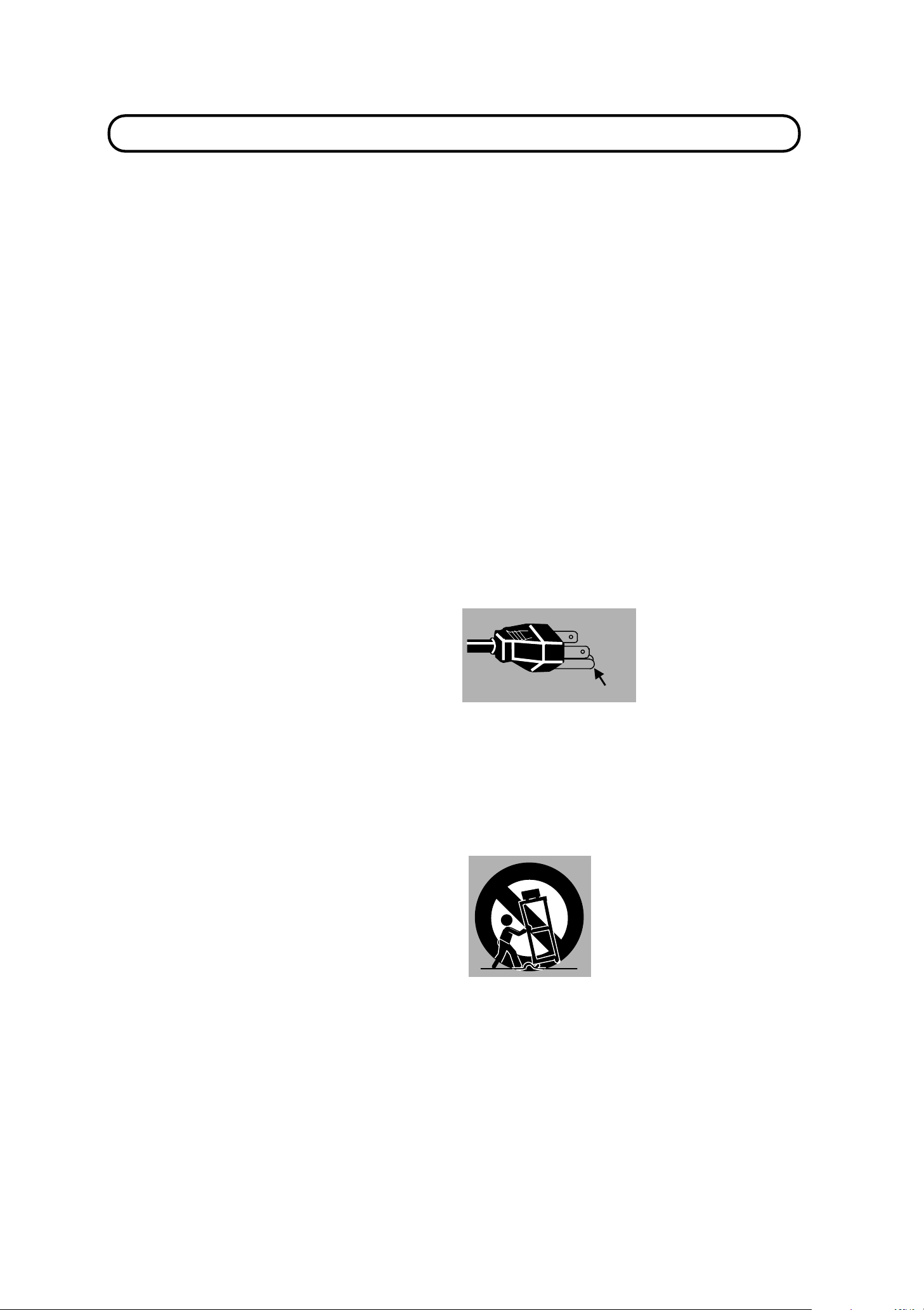
This projector is equipped
with a grounding type AC
line plug. Should you be
unable to insert the plug
into t he outlet , cont act yo ur
GROUND
Follow all warnings and instructions marked on the
projectors.
electrician. Do not defeat
the safety purpose of this
grounding t y pe plug.
Do not overload wall outlets an d ext ension cords as this
can result in fire or e lec tric shock . Do not allow anything to
rest on the power c ord. Do no t locate this projector where
the cord may be damaged by persons walk in g on it.
Never push object s of any kind into this pro jecto r throu gh
cabinet slot s as t hey m ay to uch d anger ous v oltag e point s
or short out parts that could result in a fire or electric
shock. Nev er spill liquid of an y k ind on the proje c tor.
Do not attempt to service this projector yourself as
opening or removing covers may expose you to
dangerous voltage or other hazards. Refer all servicing to
qualified service perso nnel.
For added pr otection to the pr ojector during a lig htning
storm, or when it is lef t unattende d and unused for long
periods of t ime, unplug it from t he wall outlet. This will
prevent da m age due to lightning and power line surges.
An app liance and cart combina tion
should be moved with care. Quick
stops, excessive force, and uneven
sur faces may c ause the applia nce
and cart combination to overturn.
\ 3 \
Page 4

TABLE OF CONTENTS
PAGE
INTRODUCTIO N 5
COMPATIBILITY 5
IMAGE RESOLUTION 5
PORTABILITY 5
UNPACKING THE PROJECTOR 5
TRADEMARKS 5
POWER REQUIREMENT 6
DESCRIPTIO N 7
SETTING-UP THE PROJECTOR 8-9
POSITIONING 8
ROOM LIGHT 8
VENTILATION 8
LEVELING AND ELEVATING ADJUSTMENTS 9
MOVING THE PROJECTOR 9
CONNECTING THE PROJECTOR 10-17
CONNECTING THE COMPUTER 10-14
Connecting an IBM-com p atible deskto p c omputer 11
Connecting a Macintosh desktop com puter 12
Connecting an IBM-com p atible laptop computer 13
Connecting a Macintos h PowerBook c o m puter 14
CONNECTING THE VIDEO EQUIPMENT 15-16
CONNECTING AN EX TERNA L S PE AKER 17
OPERATION OF CONTRO LS 18-20
TOP OF THE PROJECTOR 18-19
REAR OF THE PROJECTOR 20
OPERATION OF REMOTE CONTRO L 21-23
REMOTE CONTROL BATTERY INSTALLATION 23
USING THE REM OTE CONTROL UNIT 23
CONTROL THE PROJE CTO R 24-26
DIRECT OPERATION 24
MENU OPERATION 25-26
USING THE PROJECTOR 27-46
TO TURN ON THE PROJ ECTOR 27
TO TURN OFF THE PRO J ECTOR 27
DIRECT OPERATION 28
MODE SELECT 28
SOUND VOLUM E A D J USTMENT 28
PAGE
SOUND MUTE FUNCTIO N 28
ZOOM ADJUSTMENT 28
FOCUS ADJUSTMENT 28
NORMAL PICTURE FUNCTI ON 28
FREEZE PICTURE FUNCTIO N 28
FINE SYNC ADJUSTMENT 28
MENU OPERATION 29-46
MODE SELECT 29
SOUND ADJUSTME NT 30
LANGUAGE ADJUSTMENT 30
MENU EXIT 30
COLOR SYSTEM SELECT 31
PICTURE IMAGE ADJUSTMENT 32
PICTURE SCREEN ADJUSTMENT 33
COMPUTER SYSTEM SELECT 34
COMPATIBLE COMPUTER SPECIFICATION
PICTURE IMAGE ADJUSTMENT 36
PICTURE POSITION ADJUSTMENT 37
PC ADJUSTMENT 38-41
AUTO IMAG E FUNCTION 42
PICTURE SCREEN ADJUSTMENT 43
OTHER FUNCTION SE TTING 44-46
AUTO RETRACT 44-45
BLUE BACK 44-45
DISPLAY 44-45
CEILING 44-45
REAR 44-45
LAMP AGE 46
AIR FILTER CARE AND CLEANING 47
TEMPERATURE WARNING INDICATOR 47
LAMP REPLACEMENT 48
CLEANING THE LENS 49
TROUBLESHOOTING 49-50
TECHNICAL SPECIFICATI ONS 51
35
\ 4 \
Page 5

INTRODUCTION
The Re volution¡is a mu ltimedia p rojecto r designed f or port ability, durabilit y, and eas e o f use. The Re volution utilizes
built-in mu lt imedia features, a pale tte of 16. 77 m ill ion colors, and active matrix liquid cr y s t al display (LCD) t e c hn ology.
COMPATIBILI TY
The project or is compatible with many d if ferent t y p es o f personal computers an d v id eo devices, inc lu ding;
IBM-com p atible comput e rs, including la ptops, up t o 12 80 x 1024 reso lution.
Apple Macint osh and Power B ook comput ers up to 1280 x 1024 re s olution.
Various VCRs, v id eo dis c p lay ers, video c a m eras, satellite TV tune r s or other AV e qu ipment using a ny of the worldwide
video standar ds NTS C, NTSC4.43, PAL an d S ECAM .
IMAGE RESOLUTION
The r esolut ion of the pr ojector 's pr ojected im age is 1024 x 768. The p rojecto r display s comput er imag es just as they
appear on your computer's monitor. Screen resolutions between 1024 x 768 and 1280 x 1024 are compressed to 1024
x 768. The projector cannot display screen resolutions above 1280 x 1024. If your computer's screen resolution is
higher than 12 80 x 1024, res et it to a lowe r resolution be fore you connect the pr o jec tor.
PORTABILITY
The project or is extrem ely compact in size and we ight. Having a sophistica ted shape like an attach È case with a
retract ab le c ar r ying han dle , th e pr oje ct o r will help yo u ma ke powe rf u l pr es ent at ions whe re ver you go. To st re ng the n the
portability , t he LENS RETRACT f unc t ion is des igned t o pr ot e ct t he len s f r om be ing da ma ged du rin g tr an spo rt a t ion. Wit h
this functio n, the lens is pu lled in when not in use.
UNPACKING THE PROJECTOR
The pr ojector com es with t he par ts shown list ed be low. Check t o mak e sure a ll ar e includ ed. If any p arts ar e miss ing,
contact Boxlight.
User's Gu ide .
AC Power Cord.
Remote Cont r ol Transmitter Unit and b atteries.
Lens Cover.
Protective Dust Cove r .
VGA Cable.
VGA/MAC Adapter.
Mouse Cable for PS/2 por t.
Mouse Cable for serial port.
Mouse Cable f or ADB port .
TRADEMARKS
Apple, Macintosh, and PowerBook are trademarks or registered trademarks of Apple Computer, Inc.
IBM and PS/2 are trademarks or registered trademarks of International Business Machines, Inc.
5
\
\
Page 6
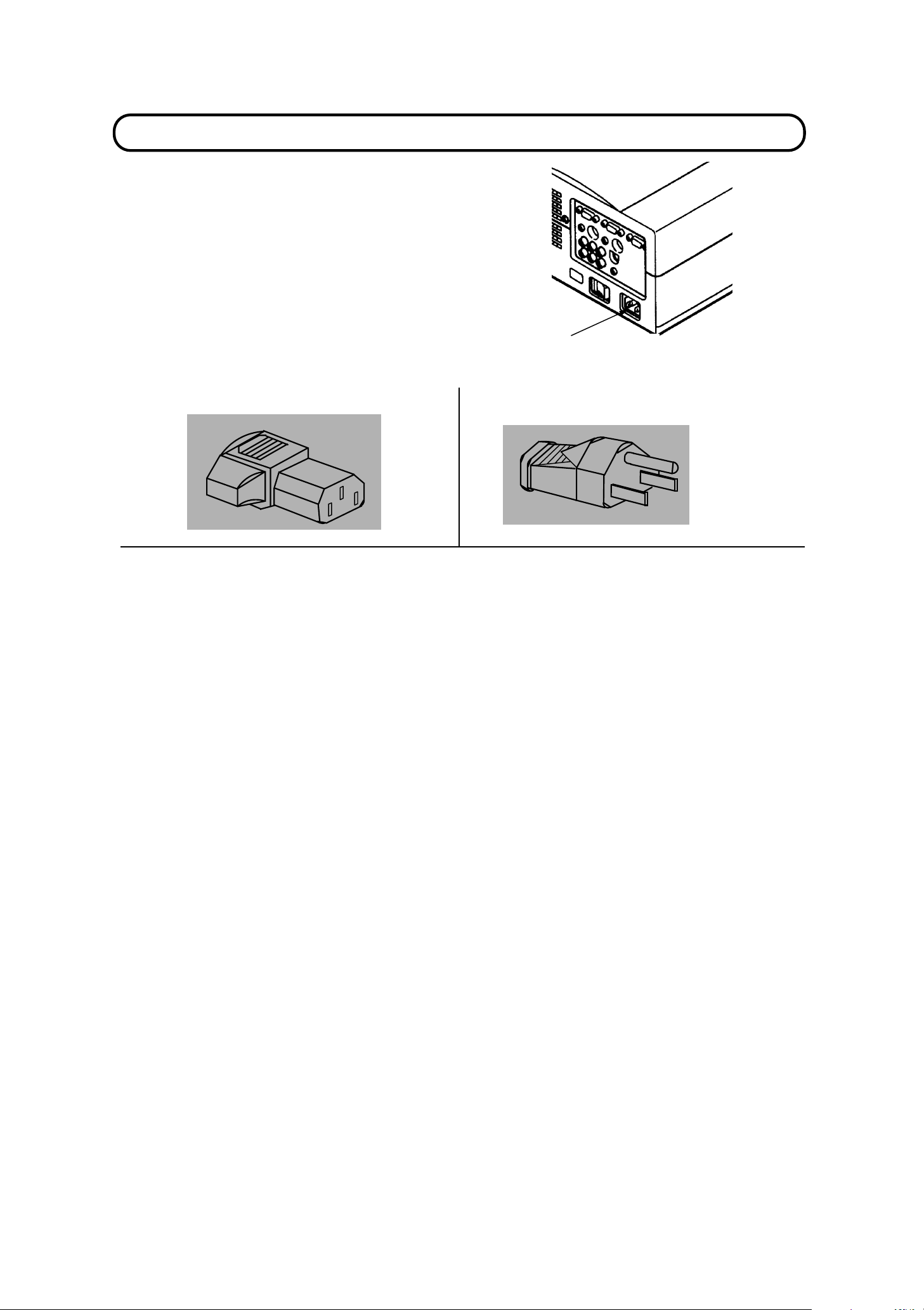
POWER REQUIREMENTS
Y
VAC
our projector uses nominal input voltages of 100-120
200-240 VAC. Th e projector autom atically selects the co rrect
input voltage. The projector is designed to work with
single-phase power systems having a grounded neutral
conductor. To reduce the risk of electrical shock, do not plug into
any other type of power system. Consult your authorized dealer
or service station if you are not sur e what type of power is
supplied to y o ur building.
or
Projector side (Female) AC outlet side (Male)
Connect the AC power
supply cord (supplied) to
the proje c tor.
\ 6 \
Page 7
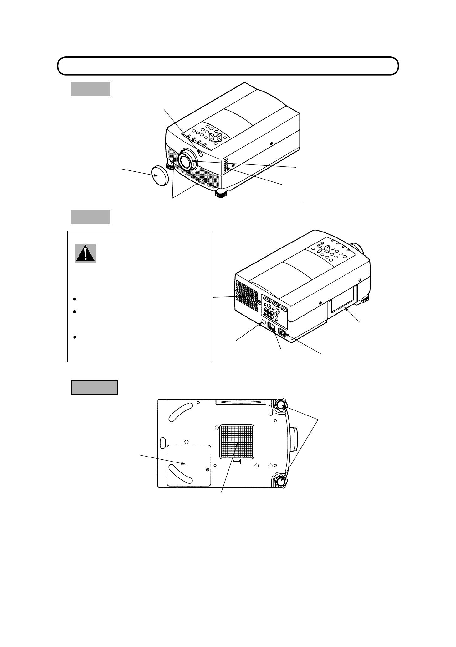
FRONT
DESCRIPTION
INFRARED
REMOTE
RECEIVER
REMOVABLE
LENS COVER
SPEAKER
REAR
EXHAUST VENT
CAUTION HOT AIR !
Air blown from the exhaust vent is hot.
Observe the following when handling your
projector or choosi ng a location to install it.
Keep heat-sensitive objects away from the
exhaust port.
If you se t the projector on top of a metallic
surface, t he surface will become hot bec ause
of the hot air exhaust. Be careful when
handling.
Do not touch the cabinet near the exhaust
vent area, an d especially screws and metallic
parts. T hese parts will beco me hot while the
projector is used.
INFRARED
REMOTE
RECEIVER
PROJECTION LENS
AIR INTAKE
VENT
MAIN ON/OFF
SWITCH
CARRY HANDLE
POWER CORD
CONNECTOR
BOTTOM
LAMP COVER
LEVELING/ELEVATING
FEET
AIR INTAKE
VENT
\ 7 \
Page 8
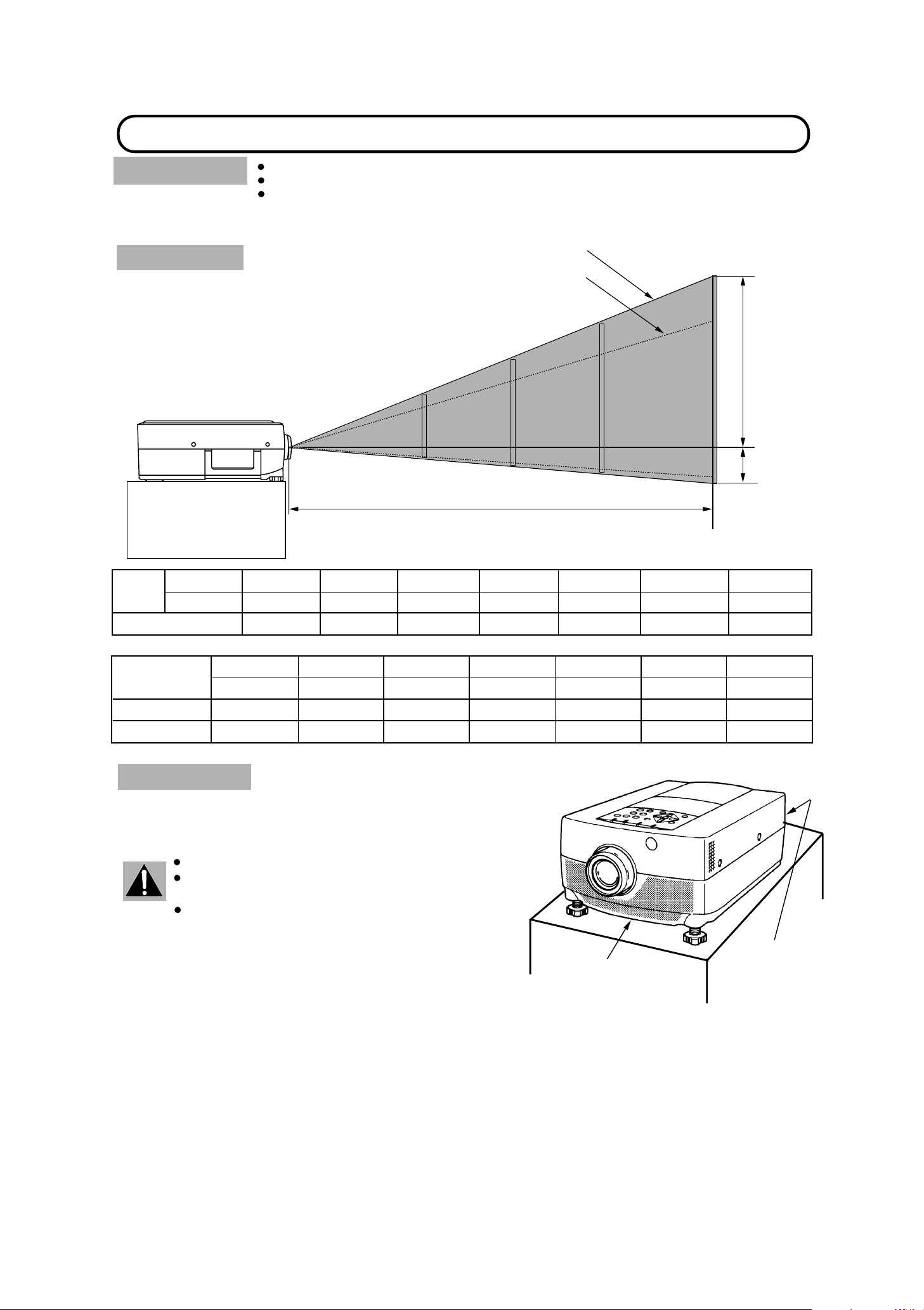
SETTING-UP THE PROJECTOR
POSITION IN G :
This projector is basically designed to project on a f la t projection surface.
This projector can be fo c u s ed from 3. 6' (1.1m) - 47' (14.3m).
Use the illust r ation below as a n example when pos itioning the projector to the scr ee n.
ROOM LIGHT
Ideally the projector should b e placed in a
room with limited light . Pictur e qua lity will be
directly affected b y ligh ting conditions.
100"
62"
Maximum Zoom
Minimum Zoom
200"
125"
DISTANCE
300"
188"
400"
250"
H1
H2
Screen
Size
Screen Size
(W ~H) inch
Height (H1)
Height (H2)
Max. Zoom
Min. Zoom
Distance
3.6'(1.1 m)
20"
16 x 12
10.7 inch
1.3 inch
32"
20"
60"
37"
6.9'(2.1 m) 11.8'(3 .6 m)
60"
49 x 36
32 inch
4 inch
100"
62" 94"
17.8'(5 .4 m)
100"
80 x 60 120 x 90
53 inch
7 inch
VENTILATION
This projector is equipped with a cooling fan to protect it from
overheat ing. Pay att entio n to the fo llowing to ensur e the vent ilat ion
and avoid a poss ible risk of fire and malfunction.
Do not cove r the vents wit h papers or other mat erials.
Keep the rear grill at leas t 3. 3' (1m) away from any
object.
Make sure that there are no objects under the
projecto r. An object und er the projecto r may preve nt
the project or from taking the cooling air t hrough the
bottom vent.
150"
150"
80 inch
10 inch
200"
125"
23.7'(7.2 m)
200"
160 x 120 240 x 180
106 inch
14 inch
AIR INTAKE VENT
(BOTTOM SIDE)
300"
188"
35.2'(10.7 m) 47'(14.3 m)
300"
160 inch
20 inch
400"
250"
400"
320 x 240
212 inch
28 inch
EXHAUST VENT
(REAR SIDE)
8
\
\
Page 9
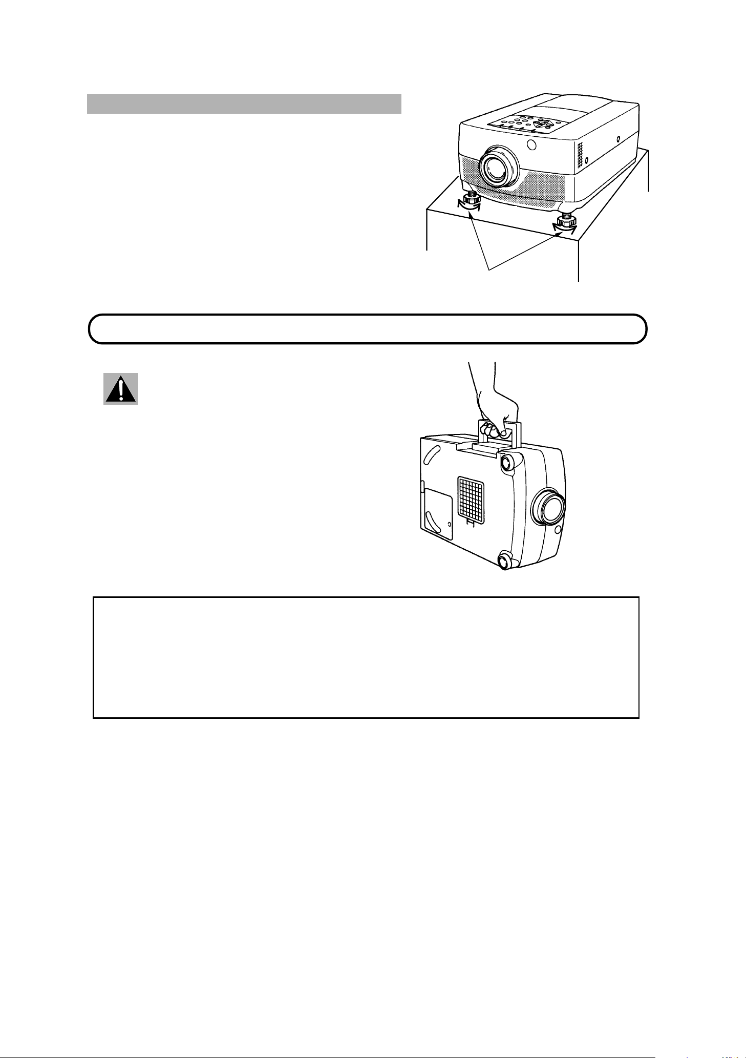
LEVELING AND ELEVATING ADJUSTMEN TS
Two feet adjus t the projec tion angle.
The projection angle can be adjusted up to 6 ° degrees by
rotating the two (left and right) feet located on the bottom of the
projector.
MOVING THE PROJECTOR
Use the carry handle when m o v ing the project o r .
Retract t he le ns, re place t he lens cove r and r ota te
the leveling/elevation feet fully clockwise when
moving the projector to prevent damage to the
projector.
UP
DOWN
UP
DOWN
LEVELING/ELEVATION
FEET
CAUTION IN CARRYING OR TRANSPORTING THE PROJECTOR
Do not drop o r b u m p the project or, other wis e d amage or mu lfunction ma y result.
When carry in g the projector, use a B oxlight recommended Carr y in g Case.
Do not tr anspor t t he pr oject or by using a courie r or tr ansp ort se rvice in an u nsuitab le tr anspo rt ca se. This ma y
cause d amage t o the pr ojecto r. To tr anspo rt th e projec tor t hrough a courie r or tr anspo rt ser vice, u se a Boxligh t
recommended Case.
For a carr ying or tran s po r tation case s , c ontact a Box lig ht authoriz ed dealer.
9
\
\
Page 10
CONNECTING THE PROJECTOR
Pin No./Si
l
Pin No./Si
l
Y
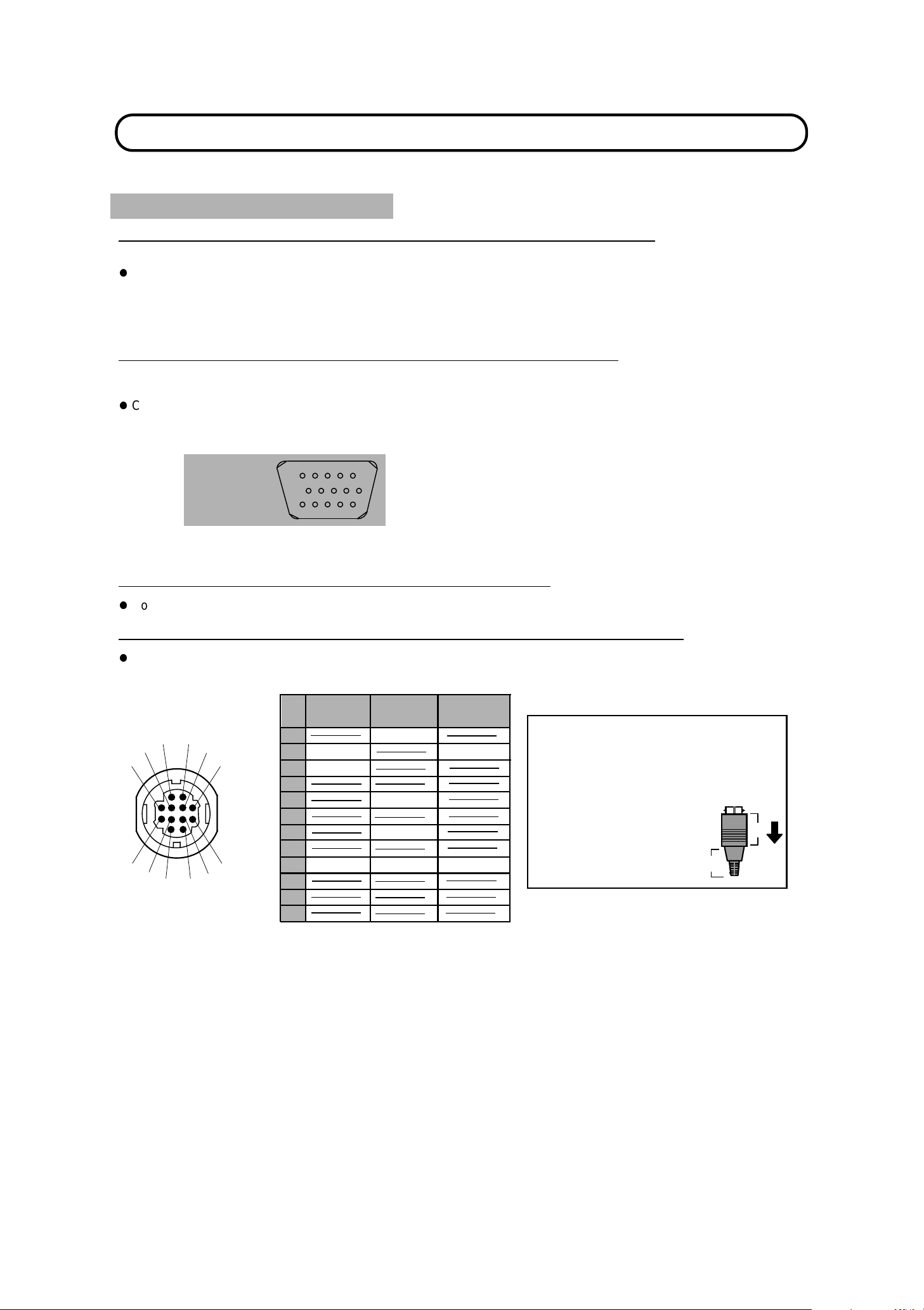
Your pro ject o r is eq uip ped wit h v ar ious a udio/ v ideo in pu ts an d ou t put s in clud ing Com put e r HDB1 5- pin (V G A) t e rm ina ls,
Monitor HDB 1 5-pin (VGA) termin als a nd S-VHS video .
CONNECTING THE COMPUTER
CONNECTING TO THE COMPUTER INPUT HDB15-PIN (VGA) TERMINALS (1 and 2)
Personal computers c a n be connecte d to the HDB15- p in (VGA) te r minal on the projector.
z
Connect t he c omputer to these terminals us ing the VGA c able and VGA/ M A C adapter ( provided).
WARNING: For projectors, t he VGA cable provided is desig ne d to reduce RFI (Radio Frequency Interference)
emissions. For reg ulator y com pliance r eason s, t his cab le must be use d and mu st no t be rep laced by any
other ca ble .
CONNECTING TO THE MONITOR OUTPUT HDB15-PI N (VGA) TERMINAL
This terminal contains the inf ormation that is viewed on the screen.
Monitor can be connected to the HDB 15 - pin (VGA) terminal on t he projecto r .
z
Connect the monitor to this ter m inal using the monitor cable (not pr ov id ed).
gna
gna
1 Red input 9 Non Connect
2 Green input 10 Ground (Vert. sync.)
3 Blue input 11 Sense 0
4 Sense 2 12 Sense 1
5 Ground (Hor iz. sync.) 13 Horiz. sync.
6 Ground (Red) 14 Vert. sync.
HDB15-PIN
TERMINAL
15
10
12345
9
6
7
8
11121314
7 Ground (Green) 15 Reserved
8 Ground (Blue)
CONNECTING TO THE COMPUTER AUDIO INPUT JACKS (1 and 2)
z
Connect audio outputs from your computer to these jacks using the audio cable (not provided).
CONNECTING TO THE MULTI-POLE 12-PIN (CONTROL PORT) CONNECTORS (1 and 2)
z
If you wish to control the computer with projector's remote control unit, you must connect control port (PS/2, Serial or
ADB port) on your com pu ter to pro jec tor's con trol port with cable. (three typ e c ables provide d)
¡ CONTROL PORT
1
2
6
10
5
9
4
3
8
1112
PS/2
Port
1
CLK
2
3
DATA
Serial
Port
TxD
4
5
ƒRxD
6
7
READ
8
GND
7
9
10
GND
11
12
ADB
Port
ADB
GND
CONTROL PORT CABLE
REMOVAL HINT
Disconnect control port cable
with following steps.
1. Hold the portion (A) of the
connector with one hand.
2. Pull the portion (B) arrow
direction an d remove
connecto r .
B
A
ƒ
NOTE: The RxD port (5 pin on the Serial Por t) is provided on cont rol port 2 connecto r only. If you contr ol the
projector by computer, you must connect control port 2 connector.
10
\
\
Page 11
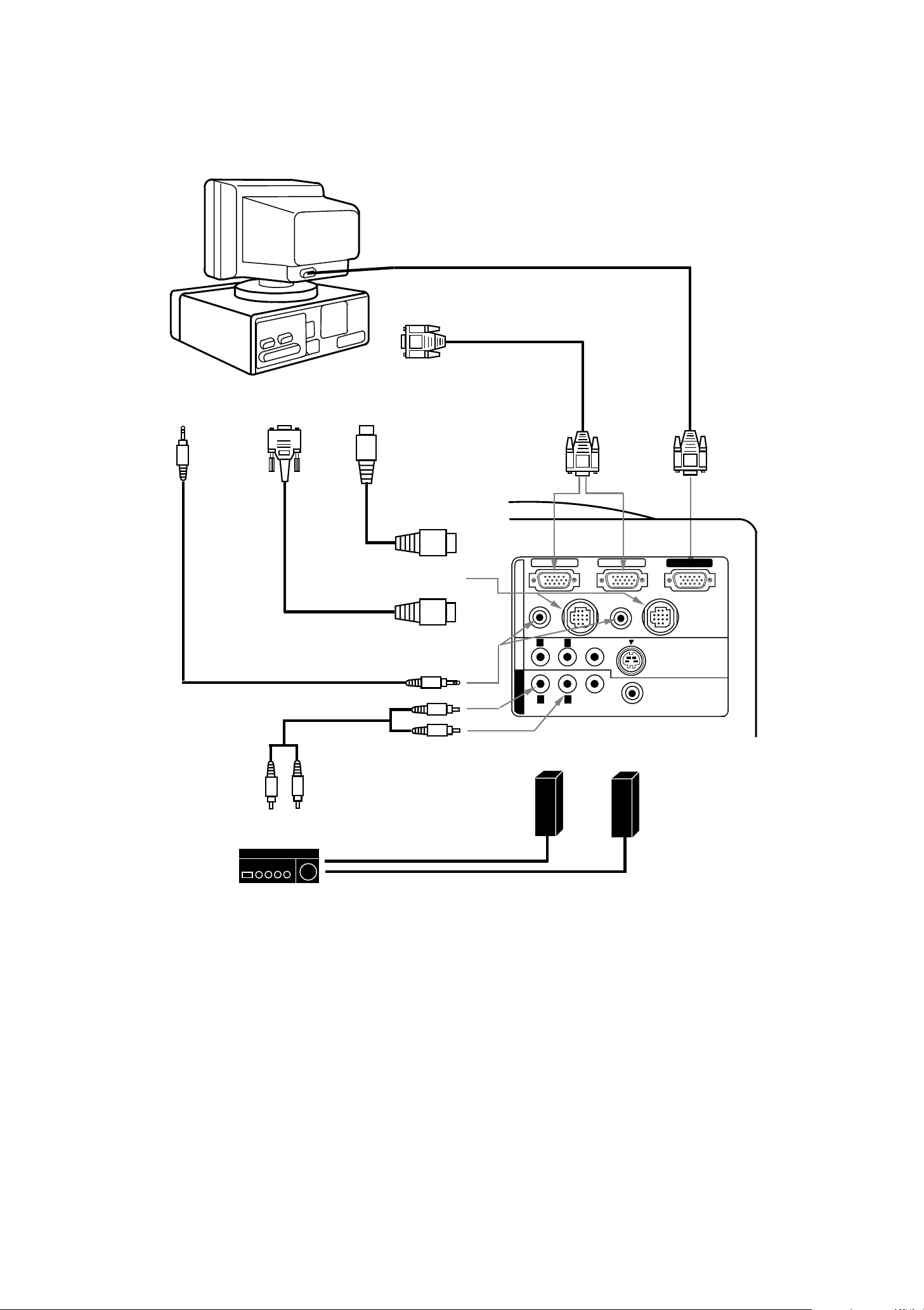
Connecting an IBM-compatible desktop computer
COMPUTER
COMPUTER
OUTPUT
VGA CABLE
(PROVIDED)
MONITO R CAB LE
(NOT PROVIDED)
AUDIO
OUTPUT
MOUSE CABLE
FOR SERIAL PORT
(PROVIDED)
AUDIO CABLE
(NOT PROVIDED)
SERIAL PO RT
INPUT
PS/2
PORT INPUT
MOUSE CABLE
FOR PS/2 PORT
(PROVIDED)
CONTROL PORT
OUTPUT 1 or 2
COMPUTER
AUDIO INPUT
1 or 2
AUDIO MONI TOR
OUTPUT
COMPUTER
INPUT 1 or 2
COMPUTER IN 1
AUDIO 1
(STEREO)
COMPUTER
R
AV IN
R
MONITOR OUT
Speaker (L)
CONTROL PORT 1
L
AUDIO
L
AUDIO
MONITOR
OUTPUT
COMPUTER IN 2
AUDIO 2
(STEREO)
VIDEO
(MONO)
VIDEO
Speaker (R)
MONITOR OUT
CONTROL PORT 2
S-VIDEO
(8 ¶)
EXT. SP
(STEREO)
R
AUDIO
INPUT
L
SPEAKER
OUT
L
R
Amp.
NOTE: The hook up s hould be done as pe r the above illus tration. A fter hook up, turn on the projec tor, mon itor,
compute r , in that o r d er.
11
\
\
Page 12
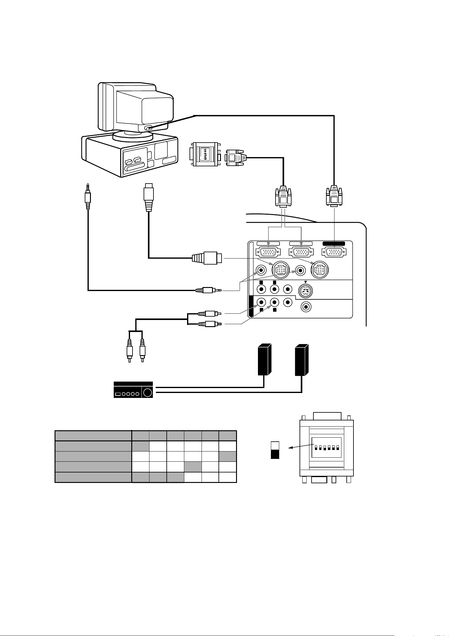
Connecting a Macintosh desktop computer
COMPUTER
COMPUTER
OUTPUT
6
3 4 5
2
ON
1
VGA/MAC ADAPTER
AUDIO
OUTPUT
ADB
PORT INPUT
MOUSE CABLE
FOR ADB PORT
(PROVIDED)
(PROVIDED)
COMPUTER
INPUT 1 or 2
MONITOR CABLE
(NOT PROVIDED)
VGA CABLE
(PROVIDED)
COMPUTER IN 1
MONITOR
OUTPUT
COMPUTER IN 2
MONITOR OUT
AUDIO CABLE
(NOT PROVIDED)
CONTROL PORT
OUTPUT 1 or 2
COMPUTER
AUDIO INPUT
1 or 2
AUDIO MO NITOR
OUTPUT
R
AUDIO
INPUT
L
SPEAKER
OUT
L
Amp.
R
Set t he slide switc hes as sho wn in t he table belo w depending on
the RESOLUTION MODE that you want to use before you turn on
the projector and computer.
RESOLUTION MODE
13" MODE ( 640 ~480)
16" MODE (8 32 ~624)
19" MODE (1 024 ~768)
21" MODE (1 152 ~870)
SW1
ON
OFF
OFF
ON
SW2
OFF
OFF
OFF
ON
SW4 SW5 SW6
SW3
OFF
OFF OFF OFF
OFF
OFF OFF
ON
OFF
OFF
ON
ON
OFF OFF
OFF
OFF
CONTROL PORT 1
AUDIO 1
(STEREO)
L
AUDIO
R
AV IN COMPUTER
L
R
AUDIO
MONITOR OUT
Speaker (L)
SW1 ‘ SW6
ON
OFF
AUDIO 2
(STER EO)
VIDEO
(MONO)
VIDEO
Speaker (R)
CONTROL PORT 2
S-VIDEO
EXT. SP
(8 ¶)
(STER EO)
VGA/MAC ADAPTER
ON
6
3 4 5
2
1
NOTE: The hook up s hould be done as pe r the above illus tration. A fter hook up, turn on the projec tor, mon itor,
compute r , in that o r d er.
12
\
\
Page 13
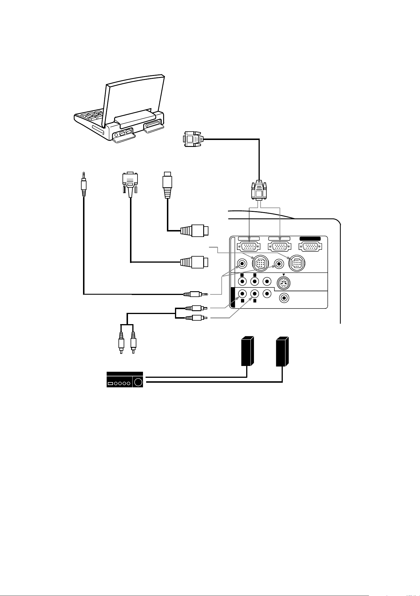
Connecting an IBM-compatible laptop computer
COMPUTER
COMPUTER
OUTPUT
VGA CABLE
(PROVIDED)
AUDIO
OUTPUT
AUDIO CABLE
(NOT PROVIDED)
SERIAL PO RT
INPUT
MOUSE CABL E
FOR SERIAL PORT
(PROVIDE D)
PS/2
PORT INPUT
MOUSE CABLE
FOR PS/2 PORT
(PROVIDED)
CONTROL PORT
OUTPUT 1 or 2
COMPUTER
AUDIO INPUT
1 or 2
COMPUTER
INPUT 1 or 2
COMPUTER IN 1
AUDIO 1
(STER EO)
COMPUTER
R
AV IN
R
MONITOR OUT
CONTROL PORT 1
L
AUDIO
L
AUDIO
(MONO)
VIDEO
VIDEO
COMPUTER IN 2
AUDIO 2
(STEREO)
MONITOR OUT
CONTROL PORT 2
S-VIDEO
EXT. SP
(8 ¶)
(STEREO)
AUDIO MONITOR
Speaker (L)
Speaker (R)
OUTPUT
R
AUDIO
INPUT
L
SPEAKER
OUT
L
R
Amp.
NOTE: The hook up should be done as p er the above illu s tration. After hook up, turn on the projec tor, computer,
in that order.
13
\
\
Page 14
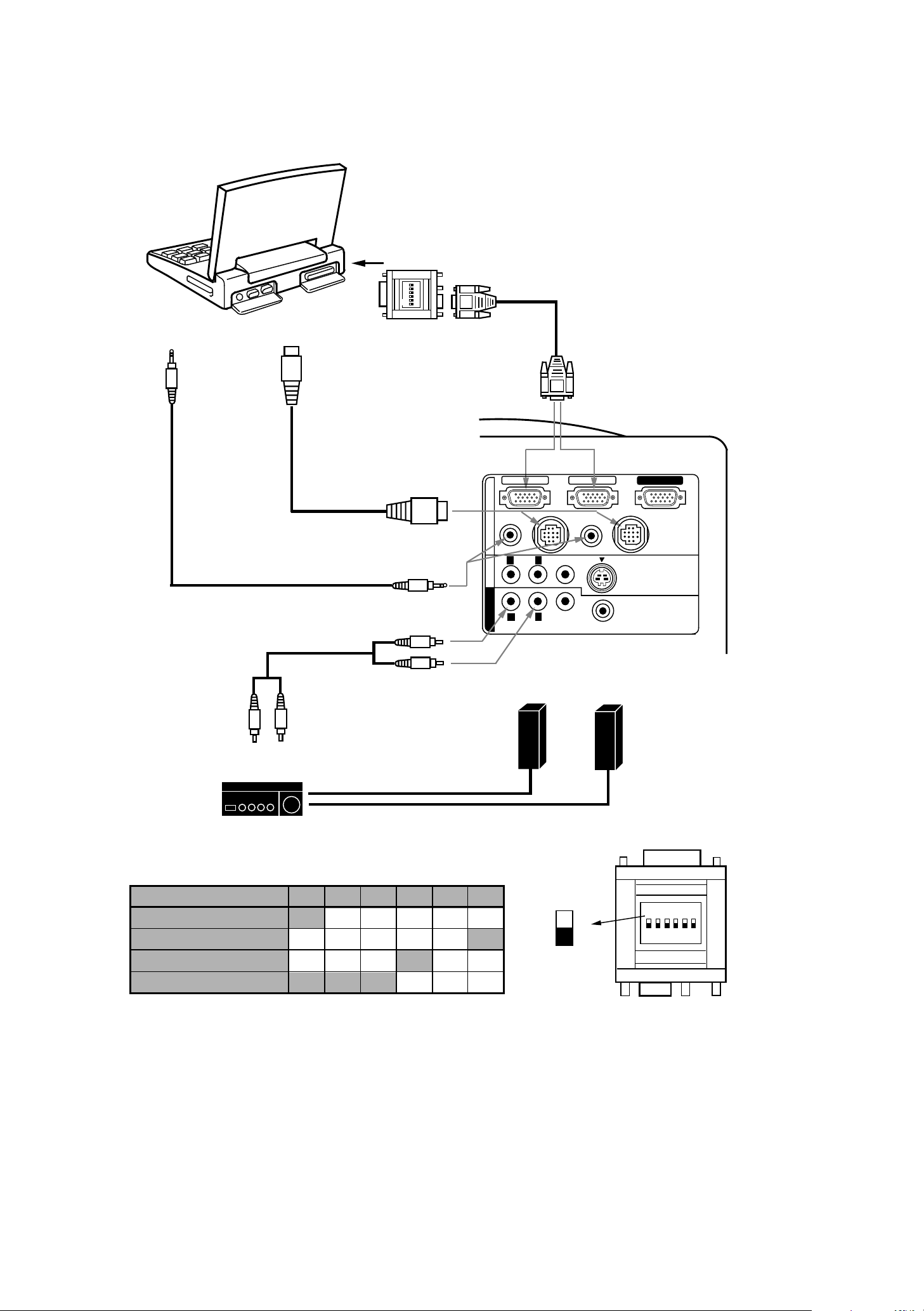
Connecting a Macintosh PowerBook computer
COMPUTER
The Macintosh PowerBook requires the use of the
PowerBook Video Adapter shipped with the
PowerBook.
TO POWERBOOK
VIDEO ADAPTER
6
4 5
3
2
ON
1
VGA/MAC ADAPTER
AUDIO
OUTPUT
ADB
PORT INPUT
MOUSE CABLE
FOR ADB PORT
(PROVIDED)
(PROVIDED)
COMPUTER
INPUT 1 or 2
COMPUTER IN 1
VGA CABLE
(PROVIDED)
COMPUTER IN 2
MONITOR OUT
CONTROL PORT
OUTPUT 1 or 2
AV IN COMPUTER
AUDIO CABLE
(NOT PROVIDED)
COMPUTER
AUDIO INPUT 1 or 2
MONITOR OUT
AUDIO MONI TOR
OUTPUT
R
AUDIO
INPUT
L
SPEAKER
OUT
L
Amp.
R
Set t he slide switc hes as shown in t he table belo w depending o n
the RESOLUTION MODE that you want to use before you turn on
the projector and computer.
RESOLUTION MODE
13" MODE (640 ~480)
16" MODE (832 ~624)
19" MODE (1024 ~768)
21" MODE (1152 ~870)
SW1
ON
OFF
OFF
ON
SW2
OFF
OFF
OFF
ON
SW4 SW5 SW6
SW3
OFF
OFF OFF OFF
OFF
OFF OFF
ON
ON
OFF
OFF
ON
OFF OFF
OFF
OFF
CONTROL PORT 1
AUDIO 1
(STEREO)
L
AUDIO
R
(MONO)
L
R
AUDIO
Speaker (L)
SW1 ‘ SW6
OFF
AUDIO 2
(STER EO)
VIDEO
VIDEO
Speaker (R)
ON
CONTROL PORT 2
S-VIDEO
EXT. SP
(8 ¶)
(STER EO)
VGA/MAC ADAPTER
ON
6
3 4 5
2
1
NOTE: The hook up s hould be done as pe r the above illus tration. A fter hook up, turn on the projec tor, computer,
in that order.
14
\
\
Page 15

CONNECTING THE VIDEO EQUIPMENT
CONNECTING TO THE AV INPUT JACKS
Connect to th e video and audio out puts of a VCR, vid eo disc player, vid eo camera, sa tellite TV tuner or other AV
equipment.
z
Connect audio/video outputs from ext ernal sources to these input jacks using the audio/video cable.
z
If the audio sig nal fro m the AV equip ment is s tere o, be sur e t o conne ct the r ight and lef t cha nnels to th e r espec tive
right and left audio input jacks.
z
If the external audio signal is monaural, connect it to the left jack.
S-VHS FORMAT VCR CONNECTION
The AV input inc ludes a n ex t r a v ideo inpu t jac k m ar k ed S- VIDE O to allow connect io n t o an S- VHS fo rm at VCR that ha s
separate Y/C video sig n a ls . The S-VIDEO jack has priority ove r the VIDEO ja c k .
CONNECTING TO THE VIDEO MONITOR OUTPUT J ACK
This jack will co ntain the video informat ion of t he select ed progr am sourc e video only. If you selec t prog ram sou rce
Computer 1 o r Computer 2, there is no signal.
Connect vide o input from AV equipment to this jack by RCA c able.
Whenever t he S-VI DEO signal so urce is v iewed on t he screen, t he video s ignal availab le at the MO NITOR O UTPUT
jack will be in black a nd white (mon oc h r ome).
CONNECTING TO THE AUDIO MONITOR OUTPUT JACKS
These jacks will cont ain the au dio infor m at ion of t he select ed pr ogra m source be ing viewed on the scr een ( Compu t er 1,
Computer 2 or Video 1) . If you h ave selec ted pr ogra m sour ce Com put er 1 the audio s ignal conne cted t o t he Com puter
1 audio input jack will be ava ilable at the audio mo n itor output jacks.
z
If the audio in put of the au dio equipment is st ereo, be su re to connec t the right and left ch annels to the r espect ive
right and left jacks.
z
If the au dio input of t he audio equipm en t is monaural, connect it to the le ft jack.
\
15
\
Page 16
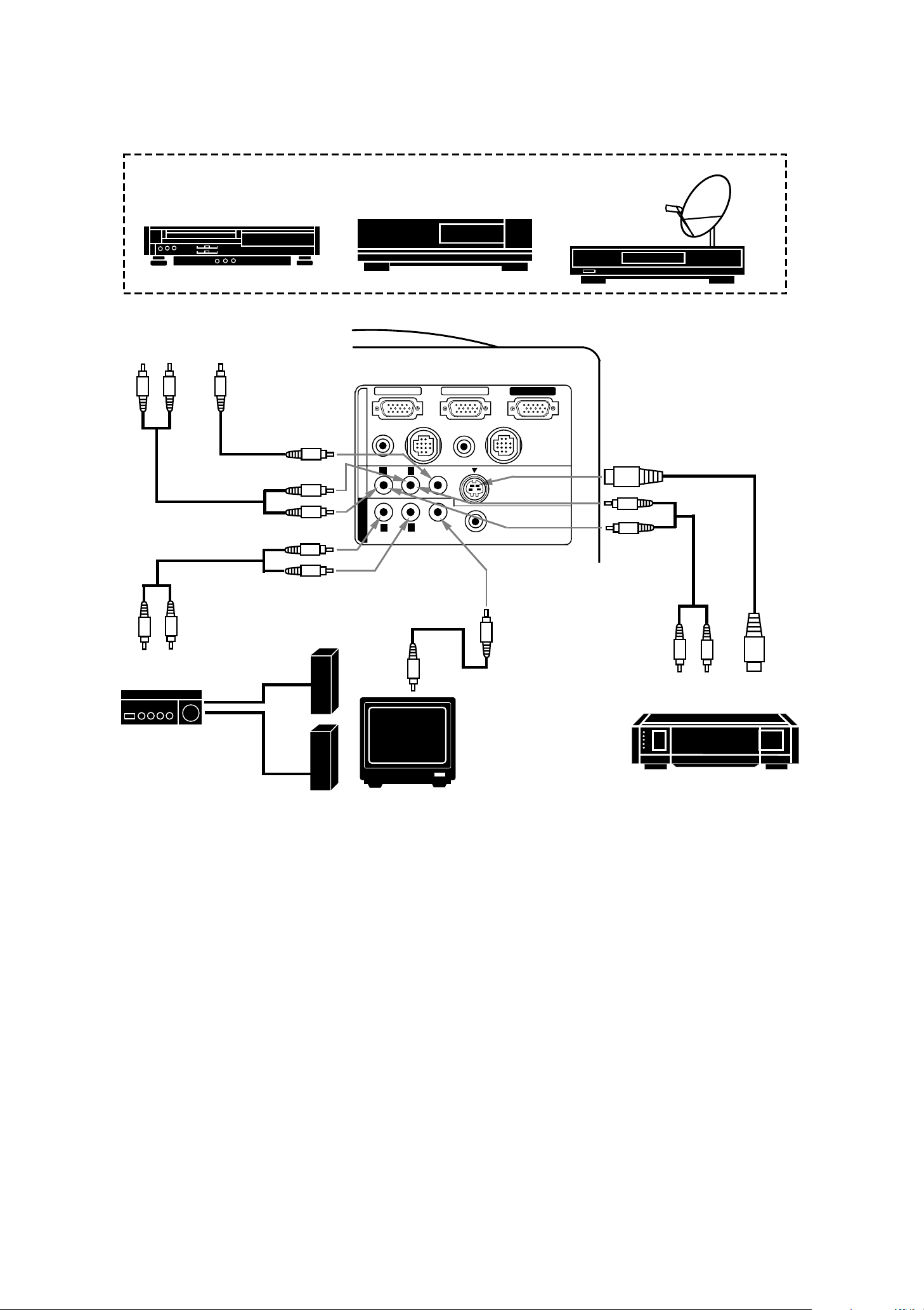
VIDEO EQUIPMENT
Connecting the Video Equipment
Video Cassette Recorder
L R
AUDIO
OUTPUT
VIDEO
OUTPUT
VIDEO INPUT
AUDIO INPUT
Video Disc Player
COMPUTER IN 1
CONTROL PORT 1
AUDIO 1
(STER EO)
COMPUTER
L
AUDIO
R
(MONO)
AV IN
L
R
AUDIO
MONITOR OUT
VIDEO
COMPUTER IN 2
VIDEO
AUDIO 2
(STEREO)
MONITOR OUT
CONTROL PORT 2
S-VIDEO
EXT. SP
(8 ¶)
(STEREO)
Satellite
TV Tuner
S-VIDEO
INPUT
AUDIO
INPUT
R
AUDIO
INPUT
L
SPEAKER
OUT
AUDIO MONI TOR
OUTPUT
Speaker (L)
L
VIDEO
INPUT
VIDEO
MONITOR
OUTPUT
AUDIO
OUTPUT
R
Amp.
S-VHS VCR
Speaker (R)
NOTE
: The hook up should be don e a s per the abov e illus tration. A fter hook u p, turn on the project or, video eq uip m ent,
MONITOR
in that order.
S-VIDEO
OUTPUT
\
16
\
Page 17

CONNECTING AN EXTERNAL SPEAKER
CONNECTING TO THE EXT. SP. JACK (3.5 mm mini stereo ty pe)
This jack outputs stereo sp eaker sound wh ich viewing on scr een. I f you use external sp eaker syste m, connect st ereo
type exte r nal speaker ja c k . Intern al s p eaker sound is d is c onnected when s peaker jack is c on nected.
EXTERNAL
SPEAKERS SYST EM
MONITOR OUT
COMPUTER
AV IN
AUDIO 1
(STER EO)
COMPUTER IN 1
CONTROL PORT 1
AUDIO
R
R
AUDIO
COMPUTER IN 2
AUDIO 2
(STEREO)
VIDEO
L
(MONO)
L
VIDEO
MONITOR OUT
CONTROL PORT 2
S-VIDEO
EXT. SP
(8 ¶)
(STEREO)
\
17
\
Page 18

OPERATION OF CONTROLS
TOP OF THE PROJECTO R
TOP CON TROL
1
2
3
TOP
CONTROL
4
14
12
ZOOM
MENU
11
LAMP
REPLACE
13
WARNING
TEMP.
FOCUS
SYSTEM
10
15
READY
FINE SYNC
NORMAL
9
LAMP
VOLUME
MODE
8
ON-OFF
5
6
7
\ 18 \
Page 19

1
LAMP REPLACEMENT INDICATOR
Light is or an ge when project io n lamp is nearin g end of servic e life.
TEMPERATURE WARNING INDI CATO R
2
Flashes red w hen internal projector temperat ure is too hig h.
3
READY INDICATOR
Light is gre en when project or lamp is ready to be turned on.
LAMP POWER INDICATOR
4
Light is dim wh en the project or is on.
Light is brig htened when the projecto r is in s tand-by mode.
5
LAMP POWER ON/OFF BUTTO N
Used to turn projection lamp on or off.
VOLUME BUTTONS
6
Used to adjus t volume.
FINE SYNC BUTTONS
7
Used to adjus t fine sync .
MODE BUTTON
8
Used to sele c t video sourc e.
(Comput er 1, Comput e r 2 or Video 1 I nput)
9
NORMAL BUTTON
Used to reset to normal picture adjustment preset by factory.
SYSTEM BUTTON
10
11
12
13
14
15
Computer Mode
Use this button, the POINT UP/DOWN/LEFT/RIGHT buttons and the SELECT button to select computer
system.
VIDEO Mode
Use this button, the POINT UP/DOWN/LEFT/RIGHT buttons and the SELECT button to select color system.
MENU BUTTON
This button will activate the MENU opera tion.
Use this button, the POINT UP/DOWN/LEFT/RIGHT buttons and the SELECT button to make adjustments to the
projector's sett ing in MENU operation.
ZOOM BUTTON
Used to sele c t power zoom lens adjust.
FOCUS BUTTON
Used to sele c t focus adjust.
POINT UP/DOWN/LEFT/ RI GHT BUTTONS
To select an it em on the M ENU that you want to ad just . To selec t an ite m, m ove t he arrow by pre ssing t hese
buttons (UP, DOWN, LEFT or RIGHT).
Used to operate power zoom lens or power focus system. (Pressing these button either UP or DOWN)
SELECT BUTTON
9
This but to n has dif fe rent func tio ns dep ending on when use d. Th is but ton is used t o exe cut e th e item select ed, to
increase or decrease the values in certain item s s uch as CONTRAST o r B RIGHTNESS.
\
19
\
Page 20

REAR OF THE PROJECTOR
19
20
23
26
COMPUTER IN 1
AUDIO 1
(STEREO)
COMPUTER
AV IN
MONITOR OUT
16
AUDIO
R
R
AUDIO
CONTROL PORT 1
L
(MONO)
L
VIDEO
17
COMPUTER IN 2
VIDEO
AUDIO 2
(STER EO)
24
MONITOR OUT
CONTROL PORT 2
S-VIDEO
(8 ¶)
EXT. SP
(STER EO)
18
21
22
25
28
16
COMPUTER INPUT- 1 TERM INAL
Used to conn ec t a comput e r to the projector.
COMPUTER INPUT-2 TERMINAL
17
Used to co nn ec t a comput er to the projector.
MONITOR OUTPUT TERMINAL
18
Used to connect a monitor to the projector.
COMPUTER AUDIO INPUT-1 JACK
19
mini stereo type
Used to conn ec t a comput e r audio input t o the
projector.
CONTROL PORT-1 CONNECTOR
20
Used to con ne c t a mouse cable to the projector.
COMPUTER AUDIO INPUT JACK 2
21
mini stereo type
Used to conn ec t a comput e r audio input t o the
projector.
CONTROL PORT-2 CONNECTOR (SERIAL PO RT)
22
Used to con ne c t a mouse cable to the projector.
NOTE: Control por t-2 connector can be als o use d
as serial port.
27
AUDIO INPUT J ACKS
23
Used to co nn ec t an audio input to the projector.
VIDEO INPUT J ACK
24
Used to con ne c t a video source to the projector.
S-VIDEO INPUT JACK
25
Used to conn ec t a S-VHS vide o s ource to the projector.
AUDIO MONI TO R OUTPUT JACKS
26
Permits au dio connect ion to a monit or.
VIDEO MO NITOR OUTPUT JACK
27
Permits video connection to a monitor.
EXT. SP. JACK (3.5 mm mini stereo type )
28
Used to connect an external speaker system.
\
20
\
Page 21

OPERATION OF REMOTE CONTROL
This remote c ontrol unit is n ot only able to ope rate th e projector
but also usable as a wir eless mo use for a P C. One point ing pad
and two click bu ttons are u s e d for wireless m o us e operation.
Wireless m ous e is usa ble wh en PC m ou se po int er is d ispla yed on
the screen. When the menu or indicator of the projector is
displayed on the screen inst ead of the PC mouse pointer, the
wireless mou se c annot be use d.
NOTE
: To use the unit as a PC wireless mouse, connect the
projector to the PC with the attached cable. Signals from
the projector are transmitted to the PC, enabling the
remote co ntrol unit of the projec tor to be used as a PC
wireless mouse. (Refer to "CONNECTING THE
PROJECTOR" in pages 10 to 14 for the connection.)
2
6
10
9
5
FRONT
M
O
O
Z
U
S
C
O
F
U
N
E
M
M
E
M
T
S
Y
S
SIDE
3
1
O
N
O
F
F
E
C
VO
L
U
M
E
L
M
O
D
E
R
E
F
E
Z
E
4
8
11
14
7
12
13
\
21
\
Page 22

LAMP POWER ON/OFF BUTTON
1
Used to tur n the projec tion lamp on or off.
2
ZOOM BUTTON
Used to sele c t power zoom le ns adjust.
FINE SYNC BUTTONS
3
Used to adjust fine sync.
4
VOLUME BUTTONS
Used to adjus t volume.
5
FOCUS BUTTON
Used to sele c t focus adjust.
6
MENU BUTTON
This b utto n will a ctiv ate t he MENU oper atio n. Use t his but ton, the POI NT UP/DO WN/LE FT/RIG HT butt on and
the SELECT (RE AR CL ICK) button to make ad jus tments t o the projec tor's set ting in MENU operation.
7
NORMAL BUTTON
Use to reset to normal picture adjustment preset by factory.
MODE BUTTON
8
Used to select video source. (Computer 1, Computer 2 or Video 1 Input)
9
SYSTEM BUTTO N
Computer Mode
Use this button, the POINT UP/DOWN/LEFT/RIGHT button and the SELECT (REAR CLICK) button to select
computer system.
VIDEO Mode
Use this button, the POINT UP/DOWN/LEFT/RIGHT button and the SELECT (REAR CLICK) button to select
color system.
SOUND MUTE BUTTON
10
Used to mute sound.
FREEZE BUTTON
11
Use this button to freeze on-screen image.
12
POINTING PAD
(POINT UP/DOWN/LEFT/RIGHT BUTTON)
When in use as a remote for the projector.
To select an item on the MENU that you want to adjust. To select an item, move the arr ow by pressing the pad
upward, do wnward, leftward or rightward.
Used to operate power zoom lens or power focus system b y pressing the pad eith er upward or downward .
When in use as a wireless mouse
Used to mo v e the pointer. The pointer is moved ac c ording to the direction you are pres s ing.
FRONT CLICK BUTTON
13
This but ton has th e s ame funct ion as the righ t butt on in a PC m ouse. P ressing t his butto n do es not aff ect any
operatio n when in MENU mode.
SELECT (REAR CLICK) BUTTON
14
When in use as a remote for the projector.
This but ton has dif fere nt func tions dep ending on when used. This butt on is us ed to execu te the ite m select ed,
to increa s e o r decrease the values in certain item s s uc h as CONTRAST or BRI GHTNESS.
When in use as a wireless mouse
This button has the sa m e function as the left bu tton in a PC mo us e.
22
\
\
Page 23

REMOTE CONTROL BATTERY INSTALLATION
123
Remove the ba ttery
compartment lid.
Slide the batteries int o the
compartment.
Note: For correct polarity (+ and -
terminal), be sure the battery
terminals are in contact with
the pins in the compartment.
Replace the c ompartment lid.
USING THE REMOTE CONTROL UNIT
Point the rem ote contro l toward the pr ojector ( Receiver window) wh enever press ing the butt ons. Maxim um operat ing
range for the remote control is about 16.4' (5m) and 60 front and rear of the projector.
16.4'
(5 m)
60
To insure safe operatio n, please obs erve the fo llowin g precaution s :
Use (2) AA t y p e alkaline batteries.
Change two batteries at the sam e time.
Do not use a n ew battery with a used bat tery.
Avoid contac t with water .
Do not drop the remot e c ontrol unit.
If batt eries have leaked on th e remote cont rol, caref ully wipe the case
clean and load ne w batteries .
23
\
\
16.4'
(5 m)
60
Page 24

CONTROL THE PROJECTOR
The project o r has two typ es of operation: DIRECT OPERA TION and MENU O P ERA TION. DIRECT O PE RATION
allows you to op erate the projector by using one button without showing the MENU. In M EN U OPERATION mod e,
you display m e nus where you c a n adjust the projector' s settings . Follow the instruction for each con trol.
DIRECT OPERATION
ADJUST ITEM
LAMP POWER ON/OFF
MODE SELECT
SOUND VOLUME
SOUND MUTE
ZOOM
FOCUS
NORMAL PICTURE
FREEZE PICTURE
FINE SYNC.
TOP CONTROL
OF THE PROJECTOR
LAMP POWER ON-OFF BUTTON
MODE BUTTON
VOLUME (+) and (-) BUTTONS
NOT AVAILABLE
ZOOM BUTTON
POINT UP/DOWN BUTTONS
FOCUS BUTTON
POINT UP/DOWN BUTTONS
NORMAL BUTTON
NOT AVAILABLE
FINE SYNC. ( + ) and (-) BUTTONS
REMOTE CONTROL UNIT
LAMP POWER ON-OFF BUTTON
MODE BUTTON
VOLUME (+) and (-) BUTTONS
MUTE BUTTON
ZOOM BUTTON
POINT (UP/DOWN) BUTTON
FOCUS BUTTON
POINT (UP/DOWN) BUTTON
NORMAL BUTTON
FREEZE BUTTON
FINE SYNC. (+) and (-) BUTTONS
\
24
\
Page 25

MENU OPERATION
ADJUST ITEM
TOP CONTROL
OF THE PROJECTOR
MODE SELECT
MENU BUTTON
POINT LEFT/RIGHT BUTTO NS
SELECT BUTTON
POINT UP/DOWN BUTTONS
SELECT BUTTON
1. COMPUTER/VIDEO MODE
ADJUST ITEM
SOUND
SOUND VO LUME
SOUND MUTE
LANGUAGE
MENU EXIT
SETTING
AUTO RETRACT
BLUE BACK
DISPLAY
CEILING
REAR
LAMP AGE
TOP CONTROL
OF THE PROJECTOR
MENU BUTTON
POINT LEFT/RIGHT BUTTO NS
SELECT BUTTON
POINT UP/DOWN BUTTONS
SELECT BUTTON
MENU BUTTON
POINT LEFT/RIGHT BUTTO NS
SELECT BUTTON
POINT UP/DOWN BUTTONS
SELECT BUTTON
REMOTE CONTROL UNIT
MENU BUTTON
POINT (LEFT/RIGHT) BUTTON
SELECT (REAR CLICK) B UTTON
POINT (UP/DOWN) BUTTON
SELECT (REAR CLICK) B UTTON
REMOTE CONTROL UNIT
MENU BUTTON
POINT (LEFT/RIGHT) BUTTON
SELECT (REAR CLICK) BUTTON
POINT (UP/DOWN) BUTTON
SELECT (REAR CLI CK) BUTTON
MENU BUTTON
POINT (LEFT/RIGHT) BUTTON
SELECT (REAR CLICK) BUTTON
POINT (UP/DOWN) BUTTON
SELECT (REAR CLI CK) BUTTON
2. VIDEO MODE
ADJUST ITEM
COLOR SYSTEM
PICTURE IMAGE
COLOR
TINT
CONTRAST
BRIGHTNESS
SHARPNESS
PICTURE SCREEN
WIDE
REGULAR
TOP CONTROL
OF THE PROJECTOR
MENU or SYSTEM BUTTON
POINT LEFT/RIGHT BUTTONS
SELECT BUTTON
POINT UP/DOWN BUTTONS
SELECT BUTTON
MENU BUTTON
POINT LEFT/RIGHT BUTTONS
SELECT BUTTON
POINT UP/DOWN BUTTONS
SELECT BUTTON
REMOTE CONTROL UNIT
MENU or SYSTEM BUTTON
POINT (LEFT/RIGHT) BUTTO N
SELECT (REAR CLI CK) BUTTON
POINT (UP/DOWN) BUTTON
SELECT (REAR CLICK ) B UTTON
MENU BUTTON
POINT (LEFT/RIGHT) BUTTO N
SELECT (REAR CLI CK) BUTTON
POINT (UP/DOWN) BUTTON
SELECT (REAR CLI CK) BUTTON
\
25
\
Page 26

3. COMPUTER MODE
ADJUST ITEM
COMPUTER SYSTEM
PICTURE IMAGE
FINE SYNC
TOTAL DOTS
CONTRAST
BRIGHTNESS
PICTURE POSITION
PC ADJUSTMENT
TOP CO NTROL
OF THE PROJECTOR
MENU or SYSTE M BUTTON
POINT LEFT/RIGHT BUTTO NS
SELECT BUTTON
POINT UP/DOWN BUTTONS
SELECT BUTTON
MENU BUTTON
POINT LEFT/RIGHT BUTTO NS
SELECT BUTTON
POINT UP/DOWN BUTTONS
SELECT BUTTON
MENU BUTTON
POINT LEFT/RIGHT BUTTO NS
SELECT BUTTON
POINT LEFT/RIGHT/UP/DOWN
BUTTONS
SELECT BUTTON
MENU BUTTON
POINT LEFT/RIGHT BUTTO NS
SELECT BUTTON
POINT UP/DOWN BUTTONS
SELECT BUTTON
REMOTE CONTROL UNIT
MENU or SYSTEM BUTTON
POINT (LEFT/RIGHT) BUTTON
SELECT (REAR CLICK) BUTTON
POINT (UP/DOWN) BUTTO N
SELECT (REAR CLICK) BUTTON
MENU BUTTON
POINT (LEFT/RIGHT) BUTTON
SELECT (REAR CLI CK) BUTTON
POINT (UP/DOWN) BUTTON
SELECT (REAR CLI CK) BUTTON
MENU BUTTON
POINT (LEFT/RIGHT) BUTTON
SELECT (REAR CLI CK) BUTTON
POINT (LEFT/RIGHT/UP/DOWN)
BUTTON
SELECT (REAR CLI CK) BUTTON
MENU BUTTON
POINT (LEFT/RIGHT) BUTTON
SELECT (REAR CLI CK) BUTTON
POINT (UP/DOWN) BUTTON
SELECT (REAR CLICK) BUTTON
AUTO IMAGE
FINE SYNC
TOTAL DOTS
POSITION
PICTURE SCREEN
TRUE
EXPAND
COMPRESSED
PANNING
NOTES:
1. The MENU, on ce activat ed, will not dis app ear un less yo u ha ve c hoos e ME NU E XIT oper at io n. I f you swit ch
to DIRECT operation by pressing a DIRECT operation button while in MENU mode, the menus will
disappear and the MENU op eration will end.
2. You can use the REMO TE CO NTROL UNIT or the TO P CO NTROL OF THE PROJ ECTOR to oper ate t he
MENU operation.
MENU BUTTON
POINT LEFT/RIGHT BUTTO NS
SELECT BUTTON
POINT UP/DOWN BUTTONS
SELECT BUTTON
MENU BUTTON
POINT LEFT/RIGHT BUTTO NS
SELECT BUTTON
POINT UP/DOWN BUTTONS
SELECT BUTTON
POINT LEFT/RIGHT/UP/DOWN
BUTTONS
MENU BUTTON
POINT (LEFT/RIGHT) BUTTON
SELECT (REAR CLICK) BUTTON
POINT (UP/DOWN) BUTTON
SELECT (REAR CLICK ) B UTTON
MENU BUTTON
POINT (LEFT/RIGHT) BUTTON
SELECT (REAR CLICK) B UTTON
POINT (UP/DOWN) BUTTON
SELECT (REAR CLI CK) BUTTON
POINT (LEFT/RIGHT/UP/DOWN)
BUTTON
\
26
\
Page 27

USING THE PROJECTOR
TO TURN ON THE PROJECTOR
Connect t he pr oje ct o r to a v ideo s our ce ( Com put e r, V CR, Vid eo Cam er a, Video Disc Pla yer , etc.) us ing t he a ppr opr iat e
terminals on the rear of the pr o jec tor (See "CONNECTING THE PRO J E CTOR" section on pages 10 - 17) .
Connect t he pro ject or' s AC powe r co rd int o a wall out let a nd tu rn t he M AIN O N/O FF swit ch (locat ed on the r ear o f t he
projector) to the ON position. Th e LAMP POWER indicator will light RED, the READY indicator will light GREEN.
Press the LAMP POWER ON/OFF button on the remote control unit or on the
projector to ON. The LAMP PO WER in dicator light will dim and the coo ling fans will
operate. The wait display appears on the screen and the count-down starts
(20-19-18-...1). The signal from the video source appears after 30 seconds.
20
CAUTION:
THIS PROJECTO R USES A METAL-HALI DE ARC LAMP. TO EXTEND THE LI FE OF THE LAM P, O NCE
YOU HAVE TURNED IT ON, WAIT AT LEAST 5 MI NUTE S BEFORE TURNING IT OFF.
NOTE:
TEMPERATURE WARNING INDICATOR flashes red, the projec tor will automatically t urn off.
Wait at lea s t 5 minutes b efore tur nin g the projec tor on.
If the TEMPERATURE WARNING INDICATOR contin ue s to flash, fo llow t he procedures be low:
(1). Press LAMP POWER ON/OFF button to OFF.
(2). Che c k the air filter for dust accumulation.
(3). Remove dust wit h v acuum cleaner (See "AI R FILTER CARE AND CLEANING " s ection on page 47.)
(4). Press LAMP POWER ON/OFF button to ON.
If the TEMP ERATURE WARNING I NDICATOR st ill c ontinue s to flash , call Boxlight or an aut horized Boxlight
dealer.
TO TURN OFF THE PROJECTOR
Press the LAMP POWER ON/OFF button on the remote control unit or on the
projector. The "Power off ?'' appears on the screen. Press again the LAMP POWER
ON/OFF but ton to tur n OFF the proje c tor. The LAM P P OWER indicator will light bright
and READY indic ator will tur n of f. The coo ling fa ns will op erat e f or 1 m inut e af ter the
projector is turn ed of f. (During this "cooling down" period, the project or cannot be
turned on. ) The READY indicator will light gr een again and the projec tor may be
turned on by pressing the LAMP POW ER ON/OFF button.
Power off ?
\
27
\
Page 28

DIRECT OPERATION
Vol
M
MODE SELE C T
Press the MODE button (located on remote control unit or on the
projector) to select Computer 1, Computer 2 or Video 1 Input. The
"Computer 1", "Computer 2" or " Video 1" display will appear on the
screen for a few seconds.
SOUND VOLUME ADJUSTMENT
Press the VO LUME buttons (locate d on remote control unit o r on the
projector ) to adjust the volume. Th e volume displa y will be displaye d on
the screen for a few seconds.
Pressing vo lum e ( +) will incr ea se v olum e and inc r eas e t he nu m be r on t he
screen.
Pressing volum e (-) will decrease volu me and decrease th e nu mber on
the screen.
SOUND MUTE FUNCTION
Pressing th e M UTE button on the rem ote control unit will mu te audio.
Press the M UTE button a gain to res tore audio t o its prev ious level. The
mute display will be displayed on the screen for a few seconds.
ZOOM ADJUSTMENT
Computer 1
Computer 2
Video 1
ume
ute
32
On
Press the ZOO M button ( located on rem ote contr ol unit or on the pro jector) an d press
POINT UP/DO WN butt on(s) to obta in your desired p icture s ize. Th e Zoom disp lay will
be displayed on the screen for a few seconds.
For a larger picture, p r ess (UP) and for a smaller picture, press (DO W N).
Zoom
FOCUS ADJUSTMENT
Press the FO CUS but ton (locat ed on remo te c ontr ol un it or o n th e proje ctor ) an d pres s
POINT UP/DO WN butt on(s) to ob tain a sha rper , crisp er pict ure. The Focus display will
be displayed on the screen for a few seconds.
Focus
NORMAL PICTURE FUNCTION
The norm al p ictur e lev el is f act ory pres et on t he pr oject or an d ca n be r est ore d anyt ime
by pressing th e NO RMAL button (lo cated on remo te control unit or on t he projector ).
The "Normal" display will be display e d on the screen for a few seconds.
Normal
FREEZE PICTURE FUNCTION
Press the FREEZE butt on on the remote cont rol unit, and th e still picture will remain on- screen. This function is
cancelled when the FREEZE button is presse d a gain or any ot h er function button is pressed.
NOTE: Your c omputer or video equipment is not affected b y this function, and will continue to run .
FINE SYNC ADJUS TMENT
Press t he FINE SYNC ( +) or ( -) but ton s (loca ted on rem ote co ntr ol unit or
on t he project or) to e liminate f licker f rom the disp lay on compu ter mode .
The F ine sync disp lay will be disp layed on the screen. Press the MENU
button (lo cate d on r emo te co ntr ol unit or on t he proje ctor ). The Fine sy nc
display will disapp ear.
NOTE: The pr ojecto r may no t repr oduce a prop er imag e f or s ome SXGA
signals. Since SXG A (1280 x 1024) imag e is converted t o XGA
(1024 x 768) image by par tial scan, some lines an d dot s of the
image do not appear. Some video noise of flicker on this
compres sed SXGA im age cann ot be eliminated even th ough you
try to make a FINE SYNC ad jus tment.
Fine sync
Total dots
Contras t
Brightness
63
1056
32
32
Reset
Stored
Quit
\
28
\
Page 29

MENU OPERATION
SYNC
NORMAL
C
Vid
C
Vid
In MENU OPERATION mode, you display menus where you can adjust the projector's settings. You can use the
TOP CONTROL OF THE PROJECTOR or the REMOTE CONTROL UNIT.
TOP CONTROL OF
THE PROJECTOR
POINT LEFT
BUTTON
MENU
MENU
BUTTON
POINT DOWN
BUTTON
MODE SELECT
POINT UP
BUTTON
SELECT
BUTTON
SYSTEM
MENU
BUTTON
5
POINT RIGHT
BUTTON
9
SYSTEM
BUTTON
SYSTEM
BUTTON
POINT
(UP/DOWN/LEFT/RIGHT)
BUTTON
Pressing t he button upwa r d ,
downward, le ftward or rightward.
REMOTE CONTROL
UNIT
O
N
O
F
FINE
M
O
O
Z
S
U
C
O
F
U
N
E
M
MUTE
M
E
T
S
Y
S
F
VO
L
U
M
E
M
O
D
E
FR
E
E
Z
E
SELECT
(REAR CLICK)
BUTTON
You can select a mode used in the MENU among c omputer 1, computer 2 and video 1.
1. Press t he MENU BUTTON and t he MAIN MENU DIS PL AY dialog box will appear .
2. Press the PO INT LEFT/RI GHT BUTTON(s) to se lect Comput er or Video and press t he SE LECT (REAR CLICK)
BUTTON. Anot h er dialog box M O DE DISPLAY will appear .
3. Press t he POINT DOWN B UTTON and a red arrow will appear.
4. M ove the arrow to the mode you want (comput er 1, comp uter 2 or v ideo 1) to use by press ing the POI NT
UP/DOWN BUTTON(s) and then press the SELECT (REAR CLICK) BUTTON.
MAIN MENU DISPLAY
omputer
Computer 1
Computer 2
eo
1
Auto
English
MODE DISPLAY
MAIN MENU DISPLAY
eo
omputer
1
VGA 1
English
Video 1
MODE DISPLAY
\
29
\
Page 30

SOUND ADJUSTMENT
C
Vid
C
Vid
C
Vid
You can adjus t the sound v olume and sound mute used in the MENU.
1. Pres s the MENU BUTTON and the MAIN MENU DISPLAY dialog box will appear.
2. Press the POI NT LEFT/RIG HT BUTTON(s ) to sele ct SOUND an d press t he SELECT (RE AR CL ICK) BUTTO N.
Another d ialog box SOUND ADJUST DISPLAY will appear.
3. Pres s the POINT DOWN BUTTON and a re d arrow will appear .
4. Move the arrow to an item that you want to adjust by pressing the POINT UP/DOWN BUTTON(s).
5. To increas e the s ound volume, point the arr ow to
decrease the sound volume, point the arrow t o
6. To mute the sound, point the arrow to Mute and then press the SELECT (REAR CLICK) BUTTON. The mute
display is changed On from Off and mute the sound.
7. To quit the MENU, point to Quit and then press the SELECT (REAR CLICK) BUTTON.
¢
and then pr ess the SELECT ( REAR CLICK) BUTTON. To
⁄
and then pr es s the SELECT (REAR CL ICK) BUTTON.
MAIN MENU DISPLAY
eo
omputer
1
VGA 1
SOUND
English
Volume
Mute
40
Off
SOUND ADJUST
DISPLAY
Quit
LANGUAGE AD JUSTMENT
The language used in the MENU is selectable from among English, German, French, Italian, Spanish and
Japanese.
1. Press the MENU BUTTON a nd the MAIN M E NU DISPLAY dialog box will appear.
2. Press the POINT LEFT/ RIGHT BUTTON(s) to select LANGUAGE and press the SELECT (REAR CLICK)
BUTTON. Anot h er dialog box LANGUAGE SETTING DISPLAY will appear .
3. Press the POINT DO WN BUTTON and a red arrow will appear.
4. Move th e ar ro w t o t h e lang ua ge yo u want to us e by pr ess ing the POINT UP / DOW N BUTTO N(s ) an d t hen p re ss
the SELECT (REA R CLICK) BUTTON.
5. The sett ing is held even if the MAIN ON/ OFF is switched off.
MAIN MENU DISPLAY
eo
omputer
1
VGA 1
LANGUAGE
SETTING DISPLAY
LANGUAGE
English
English
Deutsch
Français
Italiano
Español
Ver. 1
MENU EXIT
When in MENU mo de, press the POINT RIGHT BUTTON and s e lec t right e nd ICON, then press the SELECT (REAR
CLICK) BUTTON. M enu will be closed.
NOTE: Pres s ing the MENU BUTTON while in MENU mode. M en u will be closed.
MAIN MENU DISPLAY
eo
omputer
1
VGA 1
\
30
\
English
MENU EXIT ICON
Page 31

COLOR SYSTEM SELECT (VIDEO MODE)
C
Vid
SYSTEM
This project or is compatible wit h the four majo r broadcast v ideo standard s: PAL, SECAM, NTSC or NTS C 4.43
(COLOR SYSTEMs). It au tomatica lly adjusts itse lf to optimize it s perfor mance for t he incoming vid eo. However, if
the video signal is not strong enough to detect the video format, the projector may not r eproduce the proper video
image. In case this happens, this projector allows you to c h oose a specific broadcast s ignal forma t.
1. Connect the video eq uipment and the PROJECTOR, and turn them on.
2. Set MODE SELECT to "VIDEO MODE".
3. Press the MENU BUTTON a nd the MAIN M E NU DISPLAY dialog box will appear.
4. Press t h e PO I NT L EFT/ RIG HT BUTTO N( s ) to s elec t SY STEM and pre ss t he SELE CT ( REAR CLICK ) BUTTO N.
Another d ialog box COLO R SYSTEM DISP LAY will appear. The cur rent CO LOR SYSTEM is d isplayed in t he
system window.
5. Press the POINT DOWN BUTTON and a red arrow will appear.
6. To change the current COLOR SYSTEM, press the POINT UP/DOWN BUTTON(s) to move the arrow to a
desirable system and then press the SELECT (REAR CLICK) BUTTON.
7. The setting changed remains effective until the MAIN ON/OFF switch is turned off.
MAIN MENU DISPLAY
omputer
eo
1
Auto
Auto
PAL
SECAM
NTSC
NTSC4.43
English
COLOR SYSTEM
DISPLAY
SIMPLE METHOD
1. Press the SYSTEM BUTTON. COLOR SYSTE M DISPLAY dialog box will ap pear.
2. Press the POINT DOWN BUTTON and a red arrow will appear.
3. To change the current COLOR SYSTEM, press the POINT UP/DOWN BUTTON(s) to move the arrow to a
desirable system and then press the SELECT (REAR CLICK) BUTTON.
\
31
\
Page 32

Alth
PICTURE IMAGE ADJUSTMENT (VIDEO M ODE)
C
Vid
ough picture adjustments have been preset at the factory to our standards, you may want to change the
setting.
1. Press the MENU BUTTON a nd the MAIN M E NU DISPLAY dialog box will appear.
2. Press t he POINT LEFT/RI GHT BUTTON( s) to select IM AGE and press th e SELECT (REAR CLICK) BUTTON.
Another dialog box IMAGE ADJUST DISP LA Y will appear. This s h ows the curr en t pictur e s e ttings.
3. In th is dialog box, you c an adjust the s ettings by in creasing or d ecreasing t he levels shown as num bers. The
items and the range of the levels tha t you can adju s t are summ arized in the t able as below.
4. Press the POINT DOWN BUTTON and a red arrow will appear.
5. Move the arrow to an item that you want to adjust by pressing the POINT UP/DOWN BUTTON(s).
6. To increa s e the level, point t he arrow to
the level, point the arrow to ⁄ and then pr ess the SELECT (REAR CLICK) BUTTON.
7. You may want to store the settings in the memory so that you can recall them later. To store the settings, move
the ar row t o S tored and then p ress t he SELECT (REAR CLI CK) BUTTON. Wh en you hav e s tore d the set tings ,
"OK ?" is displayed for confirmation.
8. Move the arrow to Yes and then press the SELECT (REAR CLICK) BUTTON. The stored settings are held even
if the MAI N ON/OFF is switched off.
9. To quit t he MENU, mov e the arrow t o Quit and t hen press t h e S EL ECT (REAR CLICK) BUTTON.
10. If you do not want to store t he set tings, move the arr ow to Quit and then press the SELECT (REAR CLI C K)
BUTTON. The settings changed remains ef fective until the MAIN ON/ OFF switch is turned off.
11. To recall the settings from the memory that you have stored, move the arrow to Reset and then press the
SELECT (REAR CLICK) BUTTON. When you hav e r eset the settin gs, "OK ?" is displayed for conf irmation.
Move the arrow to Yes and then press the SELECT (REAR CLICK) BUTTON. You can adjust the settings again
if needed.
NOTE: "TINT" will be skipped during the PAL and SECAM m ode.
¢
and t hen press th e SELECT ( REAR CL ICK) BUTTON. To decr ease
omputer
eo
1
COLOR
TINT
MAIN MENU DISPLAY
IMAGE
Auto
Color
Tint
Contrast
IMAGE
Brightness
ADJUST DISPLAY
Sharpness
Reset
Stored
Quit
TABLE OF PICTURE IMAGE ADJUSTMENT
DECREASES
MORE PURPLE
0
0
32
32
32
18
32
INCREASES
63
63
MORE GREEN
English
OK ?
Yes
No
CONTRAST
BRIGHTNESS
SHARPNESS
63
63
31
BRIGHTER
SHARPER
\
32
0
0
0
\
LIGHTER DEEPER
DARKER
SOFTER
Page 33

PICTURE SCREEN ADJUSTMENT (VIDEO MODE)
C
Vid
This projector has a Wide f u nc tion, which enables you to v iew a wider video image.
WIDE function
This projector is able to proje ct not only a normal video ima ge ( with 4 x 3 asp ect ratio). But als o a wider vi deo
image by com pr es sin g 4 x 3 image. This f e at ur e ma y be use d b y t hos e who wa nt t o enjo y wat ch ing a m ov ie wit h a
cinema-like im a ge. You can swit c h either to WIDE or to RE GULAR screen mode.
1. Press the MENU BUTTON and the MAIN MENU DISPLAY dialog box will appear.
2. Press the POINT LEFT/RIGHT BUTTON(s) to select SCREEN and press the SELECT (REAR CLICK) BUTTON.
Another d ialo g box SCREEN ADJUST DIS PL AY will appear.
3. Press the POINT DOWN BUTTON and a re d arrow will appear .
4. To switch to "Wide" mode, move the arrow to Wide by pressing the POINT UP/DOWN BUTTON(s) and then
press the SELECT (REAR CLI CK) BUTTON.
5. To switch to "Regular" m ode, move the arrow to Regular by pr essing the POINT UP/DO WN BUTTO N(s) and
then pres s the SELECT (REAR CLICK) BUTTON.
6. The "Wide" s ettings rem ain s effective un til the MAIN O N/OFF switch is turned off .
MAIN MENU DISPLAY
omputer
eo
SCREEN
1
Auto
English
Regular
Wide
SCREEN ADJUST
DISPLAY
\
33
\
Page 34

COMPUTER SYSTEM SELECT (COMPUTER MODE)
C
Vid
SYS
This project o r is adjus ta ble t o dif f er ent types o f c om put er display sig nals bas ed o n V GA, SVGA, X GA or S XGA ( See
"COMPATIBLE COMPUTER SPECIFICATIONS" on the next page). If you set MODE SELECT to "COMPUTER", the
projector will a utomatic ally process the incoming signal and pr oject the pr oper image wit hout any special setting.
Although t his will wor k in m ost cas es, you ma y be req uired t o m anually set t he pr ojec tor f or some com put er signa ls.
If the co mputer image is not reprodu ced proper ly, try the fo llowing proc edure and swit ch to t he comput er display
mode that you want to use.
1. Connect the COMPUTER a nd the PROJECTOR, and turn them on.
2. Set MODE SE LECT to "CO MPUTER MO DE (1 or 2) ". This shows t he cur rent dis play mode initially det ect ed by
the projector in the system window. And "Current mode" display appears.
NOTE: 1. If the projector cannot discriminate or detect the input signal from th e computer, the "Go PC adj." display
appears.
NOTE: 2. If no input signal from the computer, the "No signal" display appears on the screen.
3. Press the MENU BUTTON an d the MAIN MENU DISPLAY dialog box will appear.
4. Press the POINT LEFT/RIGHT BUTTON(s) to select SYSTEM and pr ess the SELECT (REAR CLICK) BUTTON.
Another dialog box COM PUTER SYSTEM DISP LA Y will a ppear.
5. Press t he POINT DOWN BUTTO N an d a r ed arrow will appea r.
6. If you want to change the current display m ode, move the arrow by pressing the POINT UP/DOWN BUTTON(s) to
select one of the modes.
7. Press the SELECT (REAR CLI CK ) B UTTON to change the display mo de.
8. To quit t he MENU, move the arrow to Quit and then press the SELECT (REAR CL ICK) BUTTON.
eo
omputer
COMPUTER
SYSTEM
DISPLAY
CURRENT MODE
DISPLAY
Current m o de
H-Sync freq.
V-Sync freq.
Polarity
SIMPLE METHOD
1
36.5
60.0
H+V+
TEM
VGA 1
VGA1
VGA2
VGA3
VGA4
Quit
MAIN MENU DISPLAY
VGA1
VGA2
VGA3
VGA4
Mode 1
Quit
When the mark ( ) is displayed as BLACK,
computer syst e m mode will be a v aila ble on the
next page. Move an arrow t o the mark ( )
and press the SELECT (REAR CLICK)
BUTTON to show computer system mode
described o n the next page.
English
VGA2
VGA3
VGA4
Mode 1
Mode 2
Quit
1. Press the SYSTEM BUTTON. COMPUTER SYSTEM DISPLAY dialog box will a ppear.
2. Press the POINT DOWN BUTTON and a re d arrow will appear .
3. If you want to change the current display mode, move the arrow by pressing the POINT UP/DOWN BUTTO N(s) to
select one of the modes.
4. Press the SELECT (REAR CLI CK ) B UTTON to change the display mo de.
5. To quit t he MENU, move the arrow to Quit and then press the SELECT (REAR CL ICK) BUTTON.
PC ADJUSTMENT
This is a special fun ct ion t hat may be used when a com pu ter image is not repro duc ed pr oper ly . (See t h e p age s 38
‘
41 for mo r e detail.)
34
\
\
Page 35

COMPATIBLE COMPUTER SPECIFIC ATIONS
ON-SCREEN
DISPLAY
VGA1
RESOLUTION
640~480 31.47
H-Freq.
(kHz)
VGA2
VGA3
VGA4
VGA5
640~400
640~480
640~480
31.47
37.86
37.86
VGA6 640~480 31.70
MAC LC13
MAC 13
PC98
FM TOWNS
SVGA1
SVGA2
SVGA3
SVGA4
SVGA5
640~480
640~480
640~400
640~400
800~600
800~600
800~600
800~600
800~600
34.97
35.00
24.83
24.38
35.21
37.88
46.92
48.32
48.01
V-Freq.
(Hz)
59.88
70.09
70.09
74.38
72.81
61.91
66.60
66.67
56.42
55.40
56.33
60.32
75.08
76.33
71.98
SVGA6 800~600 37.90 61.03
SVGA7 800~600 34.50 55.38
SVGA8 800~600 38.00 60.51
SVGA9 800~600 38.60
60.31
SVGA10 800~600 47.90 71.92
SVGA11 800~600 32.70
SVGA12 800~600
MAC 16
XGA1
XGA2
832~624
1024~768
1024~768
38.00
49.72
48.36
56.28
51.09
60.51
74.55
60.00
70.26
ON-SCREEN
DISPLAY
XGA3
XGA4 720~400
XGA5
XGA6
XGA7
XGA8
RESOLUTION
1024~768
1024~76831.47
1024~768
1024~768
1024~768
1024~768
H-Freq.
(kHz)
60.08
56.47
60.31
48.50
44.00
63.48
XGA9 1024~768 36.00
MAC19
SXGA1 11 52~864
SXGA2 1280~1024
SXGA3 1280~1024
SXGA4 1280~1024
SXGA5 1280~1024
SXGA6 1280~1024
SXGA7 1280~1024
SXGA8 1280~1024
SXGA11
SXGA12
SXGA13
SXGA14
MAC21
MAC
MAC
1024~768
1152~900
1152~900
1280~1024
1280~1024
1152~870
1280~960
1280~1024
60.24
64.20
62.50
63.98
63.34
63.74
71.57
81.12
81.18
61.78
71.73
50.00
50.00
68.68
75.08
80.00
V-Freq.
(Hz)
75.10
70.06
74.92
60.02
54.58
79.35
87.17
(Interlace)
75.08
70.40
58.60
60.02
59.98
60.01
67.20
75.99
75.99
66.13
76.21
86.00
(Interlace)
94.00
(Interlace)
75.06
75.08
75.08
Specificat io ns are subjec t to change without notice.
NOTE: Basically t his p ro ject o r ca n ac ce pt t he sig na l fr om all comp ut er s wit h t h e a bov e m ent io ned V, H-Freque ncy
and less than 135 MHz of Dot Clock.
35
\
\
Page 36

PICTURE IMAGE ADJUS TMENT (COMPUTER MODE)
C
Vid
Although pic ture adjust m ents have be en preset at the facto r y to our sta ndards, you may want t o c hange the setting.
1. Press the MENU BUTTON and the MAIN M E NU DISPLAY dialog box will a ppear.
2. Press the POI NT LE FT/RIG HT BUTT ON(s) to selec t IMAGE and pre ss the SELECT (REAR CLICK) BUTTO N.
Another dia log box IMAG E A DJ UST DISPLAY will appear . This shows the current picture s ettings.
3. In this d ialog box, you c an adjust the s ettings by in creasing or d ecreasing t he levels shown as nu mbers. The
items an d the range of the levels th at you can ad jus t are summ arized in the table as below.
4. Press t h e P OINT DOWN BUTTON and a red arrow will appear.
5. Move t he arrow to an item that y ou want to adjust by pressing the POI NT UP/DOWN BUTTON(s ).
6. To increase the lev el, point the arrow to
the level, point the a r row to ⁄ and then press the SE LE CT ( RE AR CL ICK) BUTTON.
7. You may want to store the settings in the memory so that you can recall them later. To st ore the sett ings, move
the arrow to Stored and then press the SELECT (REAR CLICK) BUTTON. When you have stored the settings,
"OK ?" is dis played for confirmat ion.
8. Move the a rr ow to Yes an d t hen pr es s t h e SELE CT ( REAR CLI CK) BUTTON. The stored s et t ings ar e he ld ev en
if the MAIN ON/OFF is switched off.
9. To quit t he MENU, move the arrow t o Quit and t hen press t he SE LE CT ( RE AR CLICK) BUTTON.
10. If you do not want to store the settings, move the arrow to Quit and then press the SELECT (REAR CLICK)
BUTTON. The settings changed remains effective until the MAIN ON/OFF switch is turned off.
11. To recall the set tings from the memory that you have stored, move th e ar r o w t o Res et and t he n press the
SELECT (REAR CLICK) BUTTON. Wh en you have reset the sett ings, "OK ?" is displayed for c onfirmation .
Move th e arrow to Ye s and then press the S EL ECT (REAR CLICK) BUTTON. Yo u c an adjust the settings again
if needed.
¢
and t hen press t he SELECT (REAR CLICK) BUTTO N. To decre ase
eo
omputer
1
IMAGE ADJUST
DISPLAY
FINE SYNC
TOTAL DOTS
MAIN MENU DISPLAY
IMAGE
VGA 1
Fine sync
Total dots
Contrast
Brightness
63
1056
32
32
Reset
Stored
Quit
OK ?
Yes
No
TABLE OF PICTURE IMAGE ADJUSTMENT
Adjust the picture as necessary to eliminate
flicker from the display.
0
The number of the t otal dots in one horizontal period. Adjust the
number to match your PC image.
English
127
CONTRAST
BRIGHTNESS
LIGHTER
DARKER
\
0
0
36
63
DEEPER
BRIGHTER
63
\
Page 37

PICTURE POSITION ADJUSTMENT (COMPUTER MODE)
C
Vid
1. Press t he MENU BUTTON and the MAIN MENU DIS PL A Y d ialo g box will appear.
2. Press the POINT LEFT/RIGHT BUTTON(s) to select POSITION and press the SELECT (REAR CLICK)
BUTTON. Anot h er dialog box PO SITION SETTING DISPLAY will appear.
3. Press t he POINT DOWN BUTTON and a red arrow will appear.
4. Move the arrow to a desirable direction ( , , or ) by pressing the POINT LEFT/RIGHT/UP/DOWN
BUTTON(s) and press the S EL ECT (REAR CLICK) BUTTON to a desirable p ic ture position.
5. You may want to store the settings to the memory so t hat you can recall them later. To store the settings, move
the a rrow t o Stor ed and t hen pres s the SE LECT (REAR CLI CK) BUTTO N. When you have s tor ed the se tting s,
"OK ?" is dis pla y ed for confirmation.
6. Move the a rr ow to Yes and t hen pr ess the SELE CT (RE AR CLI CK) BUTTON. The s t or ed s et t ings ar e he ld ev en
if the MAIN ON/OFF is switched off.
7. To quit t he M E NU, move the arrow to Quit and then pr ess the SELECT (RE AR CL ICK) BUTTON.
8. If you do not wan t to s tore the settings, move t h e arrow to Quit and then press the SELECT (REAR CLI C K)
BUTTON. The settings changed remains effective until the MAIN ON/OFF switch is turned off.
9. To recall the set tings from the memory that you have stored, move the arrow to Reset and then press the
SELECT (REAR CLICK) BUTTON. When you have reset t he set tings, "O K ?" is displayed for confirmation. Move
th e arrow to Ye s and then pre ss the SELECT (R EAR CLICK) BUTTON. Yo u can adjust the setting s again if
needed.
MAIN MENU DISPLAY
eo
omputer
1
VGA 1
ÔÒ Ú
POSITION
English
POSITION SETTING
DISPLAY
Reset
Stored
Quit
OK ?
Yes
No
\
37
\
Page 38

PC ADJUSTMENT
C
Vid
Wh
This projector ca n au tomatic ally de tect most d isplay signals from m ost personal com puters cur rently distr ibuted.
However, som e c om put er s e mp loy a sp ecia l s igna l f o rm at which is d iff er en t f r om the st a ndar d on e and m ay no t b e
detected by this projector. If this happens, the projector cannot reproduce a proper image. Instead the image is
often rec o gnized as a flick ering pictur e, a non-sync h r onized picture, a non-centered pic ture or a skewed picture .
For those n on-standard fo rmats, this p rojector is pr ovided with PC ADJUST, en abling you to precis ely adjust
several param eters to match with the input signal fo rmat. The projector has eight independent mem ory areas
where you can store the parameter you have set. This enables you to recall t he setting f or a specific computer
when you need it .
1. Press t he MENU BUTTON and t h e MAIN MENU DISPLAY dia log box will appear.
2. Press the POINT LEFT/RIG HT BUTTON(s) to select PC ADJUST and press the SELECT (REAR CLICK)
BUTTON. Anot h er dialog box " W he r e to reserv e " will appear.
3. In this d ialog box, yo u w ill se lect one of t he memor y areas f rom among "Mode 1" to " Mode 8". I f parame ters
have been pr eviou sly set an d s tor ed in t he mem ory , th e s tat us "Sto red" will appea r on the co rres pondin g row. I f
not, "Free" will appear .
4. Press t he POINT DOWN BUTTON and a red a r row will appear.
5. Move t he arr ow to o ne of th e "M odes" ( Free po sition ) where you want to s tore the param eter s by pr essing t he
POINT UP/DO WN BUTTON(s). P ress the SELECT (REAR CLICK) BUTTON to select it .
NOTE; If "Stored" app ears in all Modes, no new PC parame ter data can be s tored. In t his case, clea r the PC
parameter data using the Mode free Function.
eo
omputer
1
VGA 1
MAIN MENU DISPLAY
PC ADJUST
ere to reserve
Mode 1
Mode 2
Mode 3
Mode 4
Mode 5
Mode 6
Mode 7
Mode 8
Free
Free
Free
Free
Free
Free
Free
Free
Quit
English
\
38
\
Page 39

6. Another dialog b ox "PC ADJUSTM ENT DISPLAY 1" will a ppear and th e param eter da ta for t he Mode yo u have
C
Vid
f
selected is s h own in this dialog bo x .
7. The para meters will be filled with the da ta determ in ed by the project o r a c c ording to th e p r esent signal in pu t.
8. The func tion of the pa r ameters and their values are summarized in th e t able as below.
9. Move the arrow to an item that you want to adjust by pressing the POINT UP/DOWN BUTTON(s).
¢
10. To increase the lev el, point th e arrow to
⁄
level, point the arrow to
and then pr es s t he SELECT (REAR CLICK) BUTTON.
and then pr e s s the SELECT (REAR CLICK) BUTTON. To decrease th e
11. If y ou want to st or e t he set t ing s in t he m em or y, m ov e t he ar r ow t o St or ed an d pr es s t he SELE CT ( REAR CLICK )
BUTTON. When you have stored the settings, "OK ?" is displayed for confirmation. Move the arrow to Yes and
then press the SELECT (REAR CLICK) BUTTON .
12. To recall the parameter data before setting, move the arrow to Reset and then press the SELECT (REAR CLICK)
BUTTON. When you have reset t he setting s, "OK ?" is displayed f or confirm ation. Mov e t he arrow to Yes and
then press the SELE CT ( RE AR CL ICK) BUTTON . You can adjust the settings again if needed.
13. To quit the MENU, move the arrow to Quit and then press the SELECT (REAR CLICK) BUTTON.
14. If you quit th e MENU without storing the set tings in t he memor y, the p aramete r data yo u changed will not be
kept.
15. The sto red settings are perman en tly held even if the MAIN ON/ OFF is switched off.
16. Adjust th e d ata s uch as a "Cla mp" , "Heig ht" and "Wid th" if you need ed, m ove t he ar row by pressing the PO INT
eo
omputer
ITEM
TOTAL LINES
PC ADJUST
1
VGA 1
PC ADJUSTMENT
DISPLAY 1
OK ?
Yes
No
Mode 1
Total lines
Total dots
Horizontal
Vertical
Free
630
1056
Reset
Mode
Stored
Quit
47
4
ree
English
FUNCTION
The number of the to tal vertica l line s . Adjust the number to match your P C image.
TOTAL DOTS
HORIZONTAL
VERTICAL
The number of the total dots in one horizontal period. Adjust the number to match your
PC image.
Adjustment of the horiz ontal pictur e position. When the imag e is not cen tered on t he
screen, adjust this.
Adjustmen t of the vertical pictu re position. When the im age is not centered on t he
screen, ad just th is .
39
\
\
Page 40

17. Another dialo g b ox "PC ADJUSTM ENT DISPLA Y 2 " will appear and the pa rame ter da ta fo r the M ode you hav e
f
S
Q
C
Vid
selected is s hown in this dialog b ox .
18. Move the arrow to an item that you want to adjust by pressing the POINT UP/DOWN BUTTON(s).
¢
19. To increase the lev el, point the a r row to
⁄
level, point the arrow to
and then pr es s t he SELECT (REAR CLICK) BUTTON.
and then press the SELECT (REAR CLICK) BUTTON. To decrease the
20. If you want to store the settings in the memory, move the arrow to Stored and press the SELECT (REAR CLICK)
BUTTON. When you have stored the settings, "OK ?" is displayed for confirmation. Move the arrow to Yes and
then press the SELECT (REAR CLICK) BUTTON .
21. To recall the parameter data before settings, move the arrow to Reset and then press the SELECT (REAR
CLICK) BUTTON. When you have reset the settings, "OK ?" is displayed for confirmation. Move the arrow to Yes
and then pres s the SELECT (REAR CLI CK ) BUTTON . You can ad jus t the settings again if n eeded.
22. To quit the MENU, move the arrow to Quit and then press the SELECT (REAR CLICK) BUTTON.
23. If you quit the M ENU without s toring t he setting s in the me mory, t he param eter dat a you changed will no t be
kept.
eo
ITEM
omputer
1
VGA 1
PC ADJUSTMENT
DISPLAY 2
OK ?
Yes
No
PC ADJUST
Total lines
Total dots
Horizontal
Vertical
Clamp
Height
Width
FUNCTION
Mode 1
Free
630
1056
300
Reset
Mode
tored
English
47
4
1
1
ree
uit
CLAMP
HEIGHT
WIDTH
Adjustmen t of the clamp lev e l. When the image has a dark b ar, try t his a djustment.
Expanding or c ompressing lev e l for the vertical direc t ion.
Expanding or c o mpressing le v el f or the hor izontal direct ion.
40
\
\
Page 41

MODE FREE
f
C
Vid
C
Vid
Wh
The Mode free function is provided to confirm or clear the parameter data produced by PC ADJUST.
1. Press t he MENU BUTTON and t h e MAIN MENU DISPLAY dia log box will appear.
2. Press the POINT LEFT/RIGHT BUTTON(s) to select PC ADJUST and press the SELECT (REAR CLICK)
BUTTON. Anot h er dialog box " W he r e to reserv e " will appear.
3. Press t he POINT DOWN BUTTON and a red a r row will appear.
4. Move the ar row to one of the "Mode s" (Stored position) that you want t o confirm by pressing the POINT
UP/DOWN BUTTON(s). Press t he SELECT (REAR CLICK) BUTTON. Another dialog box "PC ADJUSTMENT
DISPLAY" will appe ar.
5. To quit t he M E NU, point to Q uit and then press the SELECT (REAR CLICK) BUTTO N.
6. To modify the parameter data, perform the steps 9 - 24 of PC ADJUSTMENT SECTION.
7. To clear the parameter data, move t he arrow by pressing the POINT UP/DOWN BUTTON(s) t o select Mode f ree.
Press the SE LE CT (RE AR CL ICK) BUTTON. " O K?" is displayed f or confirmation.
8. Move t he arrow to Yes a nd then press the SELECT (REAR CLICK ) B UTTON to clear t h e paramete r d ata.
9. To quit t he M E NU, move the ar row to Quit and then pr es s the SELECT (REAR CLICK) BUTTON.
MAIN MENU DISPLAY
eo
omputer
1
VGA 1
PC ADJUST
ere to reserve
Mode 1
Mode 2
Mode 3
Mode 4
Mode 5
Mode 6
Mode 7
Mode 8
English
Stored
Free
Free
Free
Free
Free
Free
Free
eo
omputer
1
VGA 1
PC ADJUSTMENT
DISPLAY
OK ?
Yes
No
PC ADJUST
Total lines
Total dots
Horizontal
Vertical
Quit
Mode 1
Stored
630
1056
47
Reset
Mode
Stored
Quit
English
4
ree
41
\
\
Page 42

AUTO IMAGE FUNCTION (COMPUTER MODE)
C
Vid
AUTO IMAGE
The Auto ima ge f unction is provided to automatically adjust Fine sync., Total dots and Screen position for most
computers.
1. Press the MENU BUTTON an d the MAIN MENU DISPLAY dialog box will appear.
2. Pr ess the POINT LEFT/ RIGHT BUTTON(s ) to select AUTO I MAGE and pres s the SELECT (REAR CLI CK)
BUTTON. Anot h er dialog box AUTO IMAGE SETTI NG DISPLAY will appear.
3. Press t he POINT DOWN BUTTO N an d a r ed arrow will appea r.
4. Move the arrow to an item(s) you want to adjust by pressing the POINT UP/DOWN BUTTON(s).
5. Change t he s etting "On " , press t he SE LE CT ( RE AR CL ICK) BUTTON.
6. Move the arrow by pressing the POINT UP/DOWN BUTTON(s) to select Go! and then press the SELECT (REAR
CLICK) BUTTON. Th e a uto image function is st arted now. It will take 10 - 60 seconds.
7. To quit t he MENU, point to Quit an d then press the SELECT (REAR CLICK) BUTTON.
8. This setting is temp orarily effective unt il y ou turn of f the projec tor or chan ge the input signal.
NOTE: Depending upon the connected Personal Computer, t he fine sync., total dots and screen position may not
be fully adjust ed wit h the "Auto Image Func tion". In that cas e, use the "Picture I mage" and/or "Pic ture
Position" a djustments ( see pages 36 - 37) to make f ine-adjust t hem after the "Auto Im age Function" is
MAIN MENU DISPLAY
eo
omputer
1
VGA 1
English
AUTO IMAGE SETTING
DISPLAY
Fine sync.
Total dots
Position
On
On
Off
Go!
Quit
\
42
\
Page 43

PICTURE SCREEN ADJUSTMENT (COMPUTER MODE)
C
Vid
This projector has a picture scree n resize func tion, which enables you to p r o jec t the image size.
Input image
resolution
Less than XGA
(1024 x 768) image
True
Mode
Expand
Mode
Compressed
Mode
None
Panning
Mode
None
XGA (1024 x 768)
image
More than XGA
(1024 x 768) image
1. Press the MENU BUTTON a nd the MAIN M E NU DISPLAY dialog box will appear.
2. Press t h e PO INT LEFT/RIG HT B UTTO N(s) to sele ct SCRE EN a nd pr es s the SELECT (REAR CLICK ) BUTTO N.
Another dialog box SCREEN ADJUS T DISPLAY will appear.
3. Press the POINT DOWN BUTTON and a red arrow will appear.
4. To switch to "Expand mode", move the arrow to Expand by pressing the POINT UP/DOWN BUTTON(s) and then
pr es s the SELECT (REAR CL ICK) BUTTON. T he m ode is changed " Expand".
5. To switch to "True mode", move the arrow to True by pressing the POINT UP/DOWN BUTTON(s) and then
press the SELECT (REAR CLICK) BUTTON. The m o de is changed "T r u e" .
6. To switc h to "Compress ed mode " , move the arrow to Com pressed by pressing th e POINT UP/DO WN
BUTTON(s) and then pres s the SELECT (REAR CLICK) BUTTON. Th e mode is chang ed "Compressed".
7. To switch to "Pann ing mode", mov e t he arrow to Panning by pres sing the POINT UP/DO WN BUTTON(s) and
then pres s the SELECT (REAR CLI CK ) B UTTON to change to "Panning".
None
None
None
None
None
Press the POINT UP/DOWN/ L EFT/RIGHT BUTTON(s) to move the panning image position. Th e d is play of "Quit "
is ap pearing on th e s c reen during panning mode. If this dis p lay is disappeared, the pannin g mode is cancelled.
8. Press the SELECT (REAR CL ICK) BUTTON to disappear t he "Quit" display and panning m o de is cancelled.
9. This setting is temporarily effective until yo u turn off the MAIN O N/ OFF switch.
NOTE: The normal "Panning Operation" may not function properly if the computer syst em prepared with the "PC
Adjust" is us ed.
MAIN MENU DISPLAY
eo
omputer
1
VGA 1
SCREEN ADJUST
DISPLAY
SCREEN
True
Expand
True
Compressed
Panning
English
When input is VGA
(640 x 480) or SVGA
(800 x 600) image.
When input is XGA
(1024 x 768) image.
When input is SXGA
(1280 x 1024) image.
\
43
\
Page 44

OTHER FUNCTION SETTING
This projector has oth er functio n s e ttings; Au to retrac t, Blue back, Display, Ceiling , Rear and Lam p age.
AUTO RETRACT
When t his funct ion is in t he "On" posit ion, th e project or ret ract s t he lens when the pr ojecto r is t urne d of f using th e
LAMP PO WER O N/O FF but ton . To p rot ect the le ns fr om b eing da mage d while you a re ca rr ying t he pr oject or, you
are st rong ly recomm ended t o set th is functio n "On" . Since th e len s is pu lled in e ach time t he POWER is swit ched
off, y ou need to make ZOOM and FOCUS adjustment s when you turn on the projec tor.
BLUE BACK
When th is f unct ion is in th e "O n" posit ion, t he pr ojector will pr oject a b lue image with out video no ise o n the scree n
when the vide o s ource is unplug ged or tur ne d off.
DISPLAY
When this function is in the "On" p osition, on-screen displays always app ea r when adjustments are made . Although
these on-screen displays are very helpful, these may spoil the view if adjustments are made during presentations.
To avoid this, you can keep back certain displays by switching this function "Off". The followings are t he d isplays
that you c an hide.
Wait Display
Volume Display
Mute Displa y
Normal Display
CEILING
When this f unc tio n is in th e ' 'O n' ' po sit ion , t he t op/ b ot to m
and the left/right picture reverse capability lets you
project f r om a ceiling-m o unted projec tor.
REAR
When this function is in the ''On'' position, the left/right
picture reverse capab ility lets you project ont o a rear
projectio n s c reen.
LAMP AGE
The Lam p age f unct ion is d esigne d to r eset the lamp r eplace ment monit or t imer . Wh en you r epla ce the lamp, use
thisfunction reset the lamp replacement monitor timer.
\
44
\
Page 45

AUTO RETRACT, BLUE BACK, DI SPLAY, CEILING AND RE AR
C
Vid
1. Press the MENU BUTTON a nd the MAIN M E NU DISPLAY dialog box will appear.
2. Press the POINT LEFT/RIGHT BUTTON(s) to select SETTING and press the SELECT (REAR CLICK) BUTTON.
Another dialog b ox S ETTING DISPLAY will appear.
3. Press the POINT DOWN BUTTON and a red arrow will appear.
4. Move the arrow to an item you want to set by pressing the POINT UP/DOWN BUTTON(s).
5. If you want to change the setting (On or Off), press the SELECT (REAR CLICK) BUTTON.
6. To quit t he MENU, point to Quit and then press the SELECT (REAR CLICK) BUTTON.
7. The sett ings are kept e v en if the MAI N ON/OFF is switched off.
MAIN MENU DISPLAY
eo
omputer
1
VGA 1
SETTING
English
SETTING
DISPLAY
Auto retract
Blue back
Display
Ceiling
Rear
On
On
On
Off
Off
Quit
Lamp age
\
45
\
Page 46

LAMP AGE
C
Vid
NOTE: Only reset the LAMP REPLACEMENT MONITOR TIMER after lamp replacement.
1. Press the MENU BUTTON a nd the MAIN M E NU DISPLAY dialog box will appear.
2. Press the POINT LEFT/RIGHT BUTTON(s) to select SETTING and press the SELECT (REAR CLICK) BUTTON.
Another dialog b ox S ETTING DISPLAY will appear.
3. Press the POINT DOWN BUTTON and a red arrow will appear.
4. Move the arrow by pressing the POINT UP/DOWN BUTTON(s) to select Lamp age and then press the SELECT
(REAR CLICK ) BUTTON. When yo u reset t he lamp repla ce monit or, "lam p replace m onitor rese t?" is displa yed
for conf ir mation.
5. Move the arrow to Yes and then press the SELECT (REAR CLICK) BUTTON, "OK?" is displayed for
confirmat ion. Move the arrow to Yes and then press the SELECT (REAR CLICK) BUTTON, the lamp replac e
monitor is reset.
6. Move the arr ow to No and t hen pre ss the SEL ECT (REAR CLICK) BUTTO N. The lam p replace mo nitor is not
reset.
7. To quit t he MENU, mov e the arrow t o Quit and t hen press t h e S EL ECT (REAR CLICK) BUTTON.
MAIN MENU DISPLAY
eo
omputer
1
VGA 1
SETTING
DISPLAY
OK ?
Yes
No
SETTING
Auto retract
Blue back
Display
Ceiling
Rear
Lamp age
Lamp replace monitor
Reset ?
English
On
On
On
Off
Off
Quit
Yes
No
\
46
\
Page 47

AIR FILTER CARE AND CLEANING
RECOMMENDATION
Wh
FOR THE BEST IMAGE, USE THE PROJECTOR IN A CLEAN
The removab le air filter prevents dus t from ac c u mulating on the surfac e of the projec tion lens and p r ojection mirror.
Should t he air f ilter be come c logged wit h dust pa rticle s, it will r educe t he cooling f an's eff ectiv eness and m ay res ult in
internal hea t build up and r educe the life of the projector.
To clean the a ir filter, f ollow the cleaning procedures b elow:
1. Turn the LAMP POWER ON/OFF button OFF.
2. Remove t he air filter cover.
Carefully p la c e a coin against the indented part of t h e filter cov er and
lift.
3. Remove t he air filter from t h e filter cov er.
4. Clean the a ir filter with a v a c uum cleaner.
5. Replace the air filter. Make su r e that air filter cov er is fully inserted.
Do not clean with water. Doing so may da m age the air filter.
Do not oper ate the projector with air filter r e m oved.
ENVIRONMENT.
When used under the dusty or smoky conditions, particles may
accumulate on t he liquid crysta l p anel and t he lens inside. This m ay
result in a n unclear image.
en the above symptoms are noticed contact Boxlight or an
authoriz ed B ox light dealer.
AIR FILT ER
COVER
COIN
AIR FILTER
AIR FILT ER
COVER
TEMPERATURE WARNING INDICATOR
The TEMPERATURE WARNING INDICATOR flashes red when the internal
temperature of the projector exceeds the normal temperature.
Possible cau s e s for the temperature warning m ay be:
1. Ventilation slots of the projector are blocked. In such an event , repositio n
the projec tor so th at ventilat ion slots are not obstruc ted.
2. A ir filter is clogged with du st particles . Rem ove dust fro m the air filter by
following instructions in the Air Filter Care and Cleaning section a bove.
3. If tem pe rature warning indicator remains on aft e r p erforming the checks
listed above, coo ling fan/inter nal circuits may be malf unctioning. Reques t
service f r om Boxlight or an author iz ed Boxlight de ale r .
47
\
\
TEMPERATURE
WARNING
INDICATOR
Page 48

LAMP REPLACEMENT
If the lamp fails to c ome on and the lamp monitor on the projec tor light is o r ange, you m u s t replace th e bulb.
For continued safety, replace with a lamp assembly of the same type.
Allow the projector to cool for at least 45 minutes before you open the lamp cover. The
inside of the projector can become very hot.
Do not drop th e l amp mod ule or touch the g lass bu lb ! The gl ass can shatter and cause
injury.
Follow these s teps to rep lac e the lamp assembly.
1. Turn off the projector and a llow the project o r to cool th oroughly.
2. Disconnect the AC cor d from th e projector.
3. Remove screw with a screwdriver and disconnect the lamp cover.
4. Remove 2 screws with a screwdriver and pull out the lamp assembly by
grasping t h e handle.
5. Replace the lamp assembly.
6. Tighten 3 s c rews to secu r e the lamp cover to the lamp assembly .
7. Connect the detachable AC cord to the projec tor.
LAMP REPLACEMENT
INDICATOR
LAMP
COVER
8. Reset the lamp replacement monitor timer. (See "LAMP AGE" section on page 46.)
NOTE
: Only reset the LAMP REPLACEMENT MONITOR TIMER after lamp replacement.
LAMP
ASSEMBLY
HANDLE
\
48
\
Page 49

CLEANING THE LENS
Follow these s teps to clean the project ion lens:
1. Apply a non-abrasive camera lens cleaner to a soft, dry cleaning cloth.
Avoid using an excessive amount of cleaner.
Abrasive cleaners, solvents or other harsh chemicals might scratch the lens.
2. Lightly wipe the cleaning c loth over th e lens.
3. If yo u don't intend to use the projector immediate ly , replace th e le ns c over.
TROUBLESHOOTING
Before calling Boxlight for assistance, follow these steps, in this order, to make sure everything is properly
connected.
1. M ake sure you have connecte d the pr ojector to your equipme nt as described in section " CONNECTING THE
PROJECTOR" on pages 10 - 17.
2. Check cable connectio ns . Verify t ha t all compute r, video and power cord ar e properly co nn ec ted.
3. Verify that all power is s witched on.
4. If the project or still does not display an ima ge, restart the co m puter.
5. If the ima ge still does n ot display, u nplug t he projector from the computer a nd check the computer monitor's
display. The pr oble m ma y be wit h you r gr aph ics c ont r olle r r ath e r th an wit h t he pr oje ct or . ( W hen y ou r eco nnec t t h e
projecto r, r em em ber t o t ur n th e com pu ter an d mo nito r of f bef o re yo u powe r up t he pr ojec t or . Power t he equip me nt
back up in this order: Projector, monitor, computer)
6. If the problem s till exists, c h ec k the following chart.
Problem: Try these Solutions:
No power
Image is out of focus
z
Plug the projector into an AC outlet.
z
Turn the MAIN ON/OFF button to ON.
z
Press the LAMP POWER ON/OFF switch to ON.
z
Be sure the READY INDICATOR light is ON.
z
Wait one minute after the projector is turned OFF before
turning the projector back on.
NOTE: After pressing the LAMP POWER ON/OFF button to
OFF . The projector functions as follows.
1. The LAMP POWER indicator will light and the READY
indicator will turn off.
2. Aft er one minute, the READY indicator will light green again
and the projector may be turned on by pressing the LAMP
POWER ON/OFF button.
z
Check temperature warning indicator. If the indicator flashes
red, the projector cannot be turned on.
(See "USING THE PROJECTOR" section on page 27).
z
Check the projection lamp.
z
Adjust the focus.
z
Make sure the projection screen is at least 3.6 feet (1.1 m)
from the projector.
z
Check the projection lens to see if it needs cleaning.
NOTE: Moving the projector from a cool temperature location to
a warm temperature location may result in moisture
condensation on the lens. In such an event, leave the
projector OFF and wait until condensation disappears.
49
\
\
Page 50

Problem: Try these Solutions:
The lens is pulled in when the
POWER is switched off.
Picture is L/R Reversed.
Picture is T/B inverted.
Some displays are not seen
during the operation.
No sound.
Remote control unit doesn't
work.
Check AUTO RETRACT function.
(See "OTHER FUNCTION SETTING" section on pages 44 - 45).
Check Ceiling/ Rear feature.
(See "OTHER FUNCTION SETTING" section on pages 44 - 45).
Check Ceiling feature.
(See "OTHER FUNCTION SETTING" section on pages 44 - 45).
Check Display feature.
(See "OTHER FUNCTION SETTING" section on pages 44 - 45).
Check audio cable connection from audio input source.
z
Adjust audio source.
z
Press the VOLUME (+) button.
z
Press the MUTE button.
z
Check the batteries.
z
Make sure nothing is blocking between the remote control
z
sensor and remote control unit.
Make sure you are not too far from t he projector when using the
z
remote control unit. {Maximum operate range 16.4 feet (5 m)}.
Check the cable connection between the projector and the
Wireless mouse function does
not work.
z
computer.
Check the mouse setting on your computer.
z
Turn on the projector before you turn on the computer.
z
SERVICE
WARNING: High voltages are used to operate
this projector. Do not remove the back from
your uni t.
You can often correct operating problems yourself. I f
the projector fails to work properly, see
"TROUBLESHOOTING" section on pages 49 - 50. To
correct the failure, try the "Solutions."
Boxlight Service is easily obtained. If after following all
operating instructions, you find that service is
necessary, contact Boxlight for assistance at
1-800-762-5757.
\ 50 \
Page 51

SPECIFICATIONS
TECHNICAL SPECIFICATIONS
Projector Type
Dimensions (W x H x D)
Net Weight
LCD Panel System
Number of Pixels
Color System
Scanning Frequency
Projection Image Size (Diagonal)
Contrast Ratio
Horizontal Resolution
Projection Lens
Throw Distance
Projection Lamp
Projection Mirror
AV Input jacks
Computer Input Jack
Monitor Output Jack
Computer Audio Input Jack
Video Monitor Output Jack
Audio Monitor Output Jacks
Other Jacks
Multi-media Projector
10.2" (260 mm ) x 6.3" (159 mm) x 15.4" (391 mm)
13.0 lbs (5.9 kg)
1.3" TFT Active Matrix type ( Thin Film Transistor) x 3
2,359,296 {786,432 (1,024x768) x 3}
4 color system (PAL, SECAM, NTSC and NTSC4.43)
H-sync. 15 - 80 KHz, V-sync. 50 - 100 Hz
Adjustable from 20" to 400"
100 :1 (ANSI)
800 TV lines
F2.5 - 3.2 lens with f1.77" - 2.95" Motor zoom and focus
3.6' (1.1 m) - 47' (14.3 m)
UHP, 120 watt type
Dichroic mirror and X-prism system
RCA Typex1 (Video, Audio R and L)
and DIN 4 pin (S-Video) x 1
(VGA) HDB15 Terminalx2, Multi-pole 12 pin (Control port) x 2
(VGA) HDB15 Terminal x 1
Mini Stereo Type x 2
RCA Type x 1
RCA Type x 1 (R and L)
EXT. Speaker Jack x 1
Built-in Speaker
Image Elevation Adjustment
Voltage
Power Consumption
Operating Temperature
Storage Temperature
Remote Control Battery
This symbol on the nameplate means the product is Listed by Underwriters Laboratories Inc.
It is designed and manufactured to meet rigid U.L. safety standards against risk of fire, casualty
and electrical hazards.
INT. SP. Stereo (R and L), 2 watt RMS (T.H.D. 10%)
Up to 6 °
100 - 120V, 200 - 240V AC, 50/60 Hz
2.0 / 1.2A (Max. Ampere)
5 °C - 35 °C
-10 °C - 60 °C
(2) AA Type
\ 51 \
Page 52

Hill Pl
Pri
P
A)
LIMITED WARRANTY
FAX
BOXLIG HT CO RPORATION ("BOXLI GHT") warrant s t hat each Boxlight 6000 (Revolu tionV) ("the Product") sold
hereunder will conform to and function in accordance with the written specifications of BOXLIGHT. Said limited
warranty shall apply only to the first person or entity that purchases the Product for personal or business use and not
for the purp ose of distribut ion or resale. Said war ranty shall cont inue for a period of t wo (2) years fr om the date of
such pur cha se. BOXLIG HT do es not warrant that t he Pro duc t will m eet t he sp ecif ic r eq uir em ent s o f th e fir s t pe rs on or
entity t h at purchases the Product for per s onal or business use. Lamp is warrantied f o r 90 days.
BOXLIG HT CO RPORATION's liability for the breac h o f the foregoing limited war ranty is limited to the rep air or
replaceme nt of the Pr oduct or r efund of t he purcha se price of t he Product , at BOXL IGHT's so le op tion. To ex ercise
the Purcha ser's r ights un der the fo regoin g wa rrant y, the Pr oduct mus t be retu rned at t he Purchas er's sole cos t and
expense, to BO XLIGHT or any auth orized serv ice center pro vided, howev er, that t he Pr oduct mus t be accompanie d
by a wr itt en lett er explainin g th e prob lem a nd which include s (i) proof of pur cha se; (ii) t he dea ler's name; and ( iii) t he
model and seria l n umber of t he Produc t. A ret urn auth orizatio n nu mber, issu ed by the BOXL IGHT cust omer s ervice
departm e nt, must also be clearly d is played on the ou tside of th e shipping carton containin g the Product.
WARRANTY LIMITATION AND EXCLUSION
BOXLIG HT CO RPORATION shall have no f urther obligation und er the foregoing limit ed warranty if t he
Product has been damaged due to abuse, misuse, neglect, accident, unusual physical or electrical stress,
unauthor ized modification, tam pering, alterations , or service other than by BO XLIGHT or its authoriz ed
agents, ca uses other than f rom ordinary u se or failure to pro perly use the Pro duct in the applicatio n for
which said Pro du c t is intended.
DISCLAIMER OR UNSTAT ED WARRANTIES
The warranty printed a bove is the on ly warranty app lic able to this p urchase.
All other war r ant ie s exp re ss or implied, inclu ding, but n ot lim it ed t o, the impl ied war r ant ie s or m er ch ant ab ility
and fit ness fo r a par ticu lar purpo se are disclaim ed. Ther e ar e no warr anties th at exte nd be yond the f ace of
hereof and th e f oregoing warrant y shall not be extended, alt ered or varied except by wr itten instrum ent
signed by BOXLIGHT CORPORATION.
LIMITATION OR LIABILITY
It is unde rstood and agreed that BOXLIGHT's liab ility whether in contract , in tort , under an y warranty, in
negligence or o therwis e shall not excee d the re tur n o f th e a mount of t he purch ase pric e paid by pur chase r
and un der no cir cum stanc es shall BO XLIG HT be liable f or spec ial, indir ect or cons equent ial damag es. Th e
price s tate d f or the Produc t is a conside rat ion in limit ing BOXLIG HT's liability . No ac tion regar dless of for m,
arising out of the agre em ent to purch as e t he pr oduc t m ay be br ou ght by purcha ser m or e th an on e yea r aft e r
the cause of action has accrued.
nted in Japan
art No. 610 271 2537 (1AA6P1P1254A- M6KE-
1-800-762-5757
19332 Powder
Poulsbo, WA 98370-7407
http://www.boxlight.com
360-779-3299
ace
 Loading...