

Page 1
www.boxerpu
mps.
com 6900.011-01 Page 1
iD Peristaltic Pump Driver
User Manual
www.boxerpu
mps.
com 6900.011-01 Page 2
1.0
Introduction
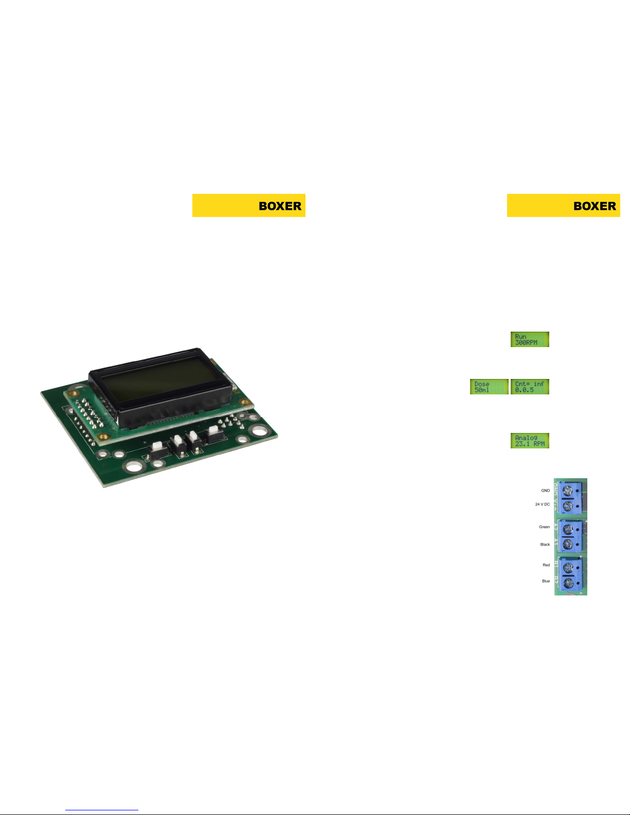
The Boxer iD Driver is a powerful digital and programmable controller designed specifically for
use with the peristaltic pumps series 25K, 15KS/QQ and 9K/QQ with stepper motors.
Features include:
►
3 Runni
ng modes (dispense, dose and analogue
)
► Calibration for volumetric dispense
► Automatic stall and open lid detection
►
Push button or remote inputs
► Acceleration, deceleration, time interval, and suck-back settings
1.1
Dispense Mode
In dispense mode the pump is switched on and off by the enter key. The display will show the
dispense volume. During running or prior to starting the speed can be
changed with the up and down keys. Programmable settings are: current, calibration, suck back, acceleration, deceleration, direction, stall and lid detections.
1.2 Dose Mode
In dose mode the pump will run a predefined dosing cycle with paused interval. The display
will show the dosed volume and count down during the
pause interval. Prior to starting the dose volume is set. Programmable setting are: current, calibration, dose speed,
dose interval, number of cycles, suck back, acceleration, deceleration, direction, stall and lid
detection.
1.3 Analog Mode
In analog mode the driver acts a pure analog driver. Inputs are: on/off, direction and
speed. The display will show the running speed. Programmable settings are:
current, acceleration, deceleration, speed range, stall and lid detection.
2.0 Setting-Up
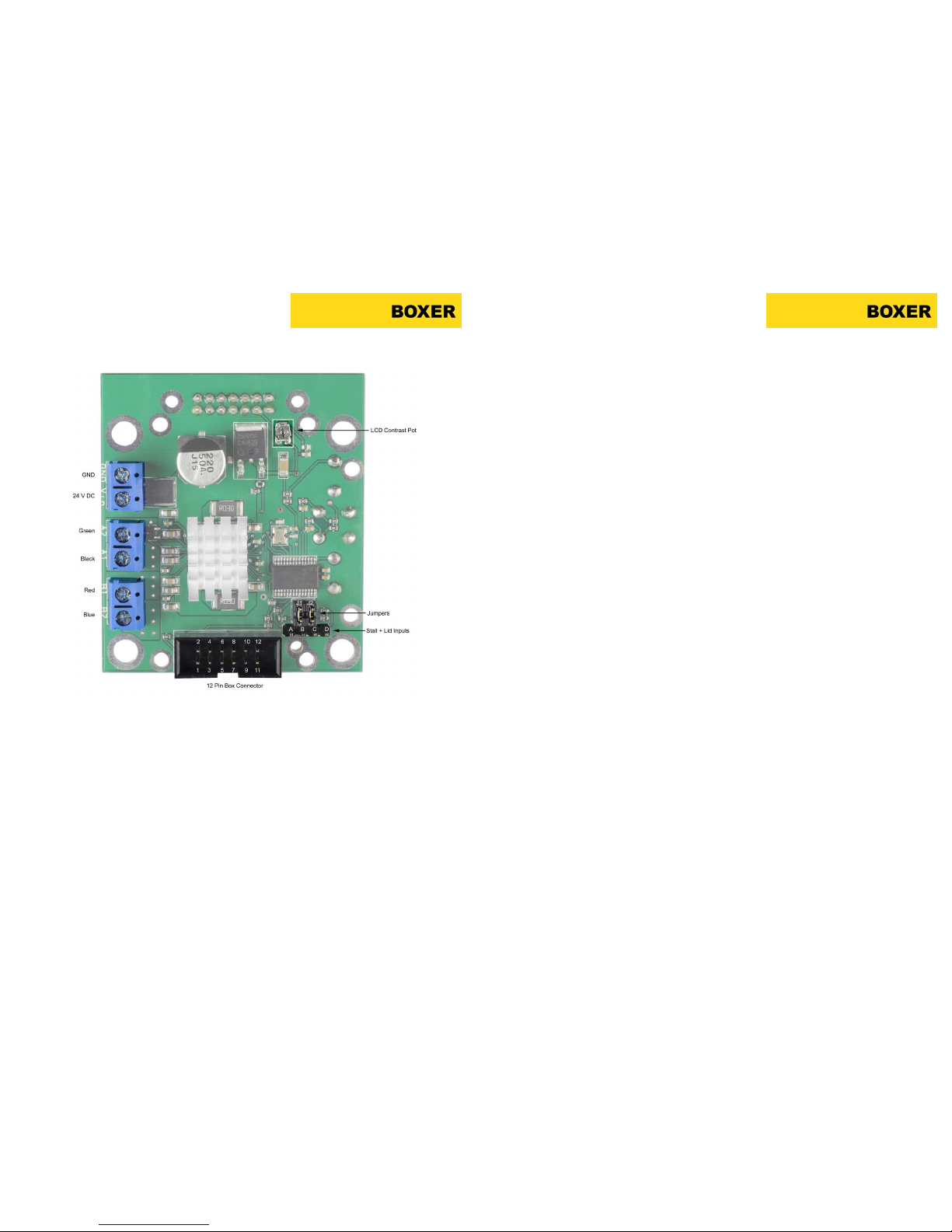
With the power supply switched off, connect the iD Driver via the blue terminal block:
GND
→ GND
24V DC → Vin
Connect the 4 colour coded wires from the stepper motor also to the blue terminal
block:
Green → A2
Black → A1
Red → B1
Blue → B2
For stall / lid detection and remote inputs, refer to section 5.2.
Switch the power supply on.
www.clarksol.com
www.clarksol.com
Page 2
www.boxerpu
mps.
com
6900.011-01 Page 3
3.0 Operation
Whe
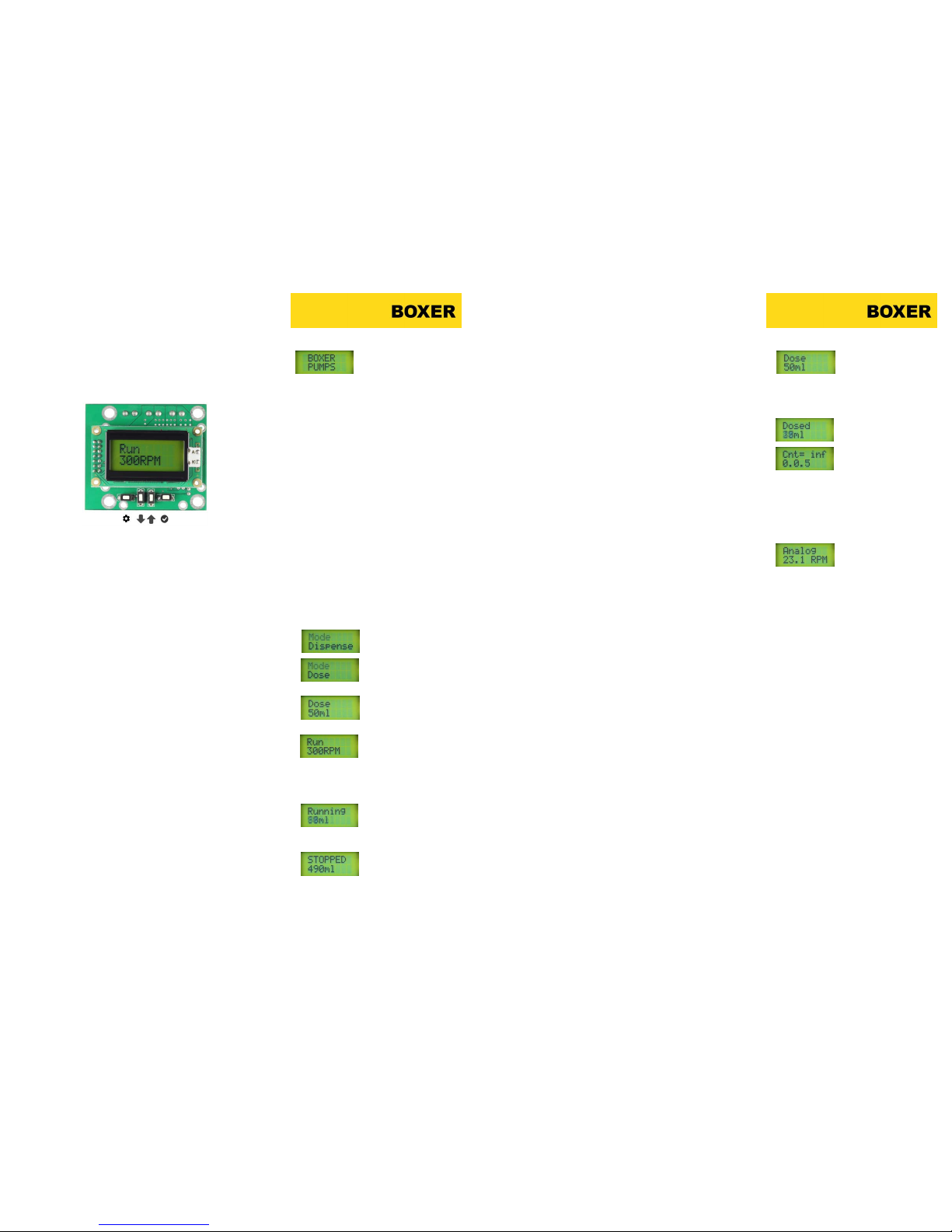
n powered up the display initially shows BOXER PUMPS. On first operation or following a reset the driver enters Dispense mode. Thereafter the driver will always return to mode last used prior to switching off.
The driver is operated using the 4 keys on the PCB under the display:
From left to right, these are referred throughout this manual as ’settings’, ‘down’, ’up’ and
’enter’. The above symbols are used in the mode settings menus (Appendix A, B and C).
3.1 Moving between modes
The following section assumes the driver is initially in Dispense mode and the
user wishes to change to Dose mode.
1 Press and hold ‘settings’. The display first shows ‘Settings’, then ‘Mode
Dispense’.
2 Press ‘enter’. The display first shows ’Changes Mode’, then ‘Mode Dis-
pense’ (with ‘Mode’ flashing).
3 Use Up and Down keys to select new mode, example ‘Mode
Dose’ (with ‘Mode’ flashing).
4 Press ‘Enter’. The display first shows ‘Mode Set’, then ‘Mode Dose’.
5 Press ‘settings’. The display first shows ’Exiting Settings’, then enters
the Dose Mode’
3.2 Using the Dispense mode
With the driver in Dispense mode the ‘Run RPM’ is shown.
1 Using the ‘up’ and ‘down’ keys the rpm can be adjusted.
2 All other settings including calibration can be adjusted in the Dispense
Settings Mode. See section 4.0.
3 Press ‘enter’ to start running.
4 The display counts up the dispensed volume (calibration is needed).
5 When running the speed can be increased / de creased using the ‘up’
and ‘down’ keys.
6 Press ‘enter’ to stop running. The dispensed volume is shown.
7 Press ‘enter’ as required to start / s top the dispensing.
8 If ‘settings ’ is pressed when stopped, the display returns to the ‘Run
RPM’. Speed can be adjusted and the dispensed volume is automatically reset to 0 ml.
www.boxerpu
mps.
com
6900.011-01 Page 4
3.3 Using the Dose mode
With the drive
r in Dose mode the ‘Dose ml’ is shown.
1 Using the ‘up’ and ‘down’ keys the dose volume can be adjusted.
2 All other settings including calibration can be adjusted in the Dispense
Settings Mode. See section 4.0.
3 Press ‘enter’ to start running.
4 The display counts up the dispensed volume.
5 Once the dose volume is reached the driver enters a interval pause.
The display counts down the time before the next dose commences.
6 Dosing continues for the set or infinite number of cycles.
7 Press ’enter’ to stop the cycle. The display first shows the volume ob-
tained in the last dose, then returns to the ‘Dose ml’ display.
3.3 Using the Analogue mode
With the driver in Analogue mode the ‘Analog RPM’ is shown. The driver acts
as a pure analogue driver and runs at all times runs according to the analogue
inputs.
The inputs are:
►
On / off (pulled up, with no input = ‘on’).
► Direction (pulled up, with no input = ‘CW’).
► Speed 0 to 5 V* (range defined in the settings, see section 4.12).
* with no speed input the RPM will drift around 20 rpm!
The location of the inputs are shown in section 5.1.
Once in Analogue mode the driver can only be stopped by changing to a different mode (press and hold ’settings’).
Since the inputs are partly also shared with the keys on the PCB, when running in analogue mode pressing and holding ‘up’ will reverse the direction
while pressing and holding ‘enter’ will stop the pump.
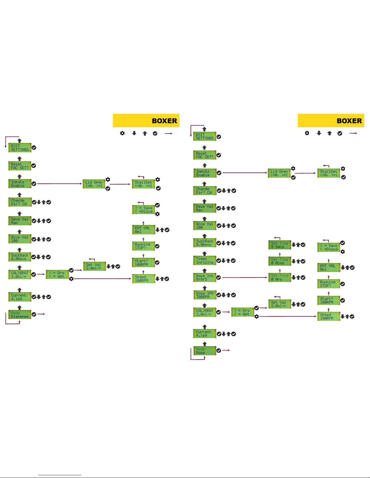
4.0 Programmable Settings
The iD driver has 12 programmable settings which are used in some or all of
the three modes. The menu structure of each of the modes is shown in a pictorial form in appendix A, B and C.
4.1 Current
(used in Dispense, Dose and Analogue mode)
It is a characteristic of stepper motors that they will run hot at slow speeds. To
reduce temperature the current setting should be set to the lowest possible
setting which does not stall the pump.
Default = 4.16A
www.clarksol.com
www.clarksol.com
Page 3

www.boxerpu
mps.
com
6900.0
11-01 Page 5
4.2 Calibrate
(Used in Dispense and Dose mode)
For volumetric dispensin
g the driver must be calibrated to the pump and tube
type / size. The calibration can be made ‘dry’ (inputting flow according to the
pump / tube data or ‘wet’ by dispensing a measured volume over a period of
several revolutions.
Default = 2 ml / revolution
4.3 Suck Back
(Used in Dispense and Dose mode)
To prevent dripping the driver c
an be programmed to reverse the flow direc-
tion by fractions or whole revolutions when the pump stops.
Note: When restarting any programmed suck back will introduce a volumetric
error. This should be added to the required volume.
Default = 0.0 revolutions
4.4 Acceleration
(Used in Dispense, Dose and Analogue mode)
The acceleration setting will ramp up the speed rather than providing a hard
start. The setting is 1 (slowest ramp up) to 255 / Max (fastest ramp up). For
high speed operation this is useful to prevent stalling.
The acceleration period is taken into consideration for all volumetric dispensing.
Default = 200
4.5 Deceleration
(Used in Dispense, Dose and Analogue mode)
Similar to acceleration this setting prevents a hard stop.
Default = Max (255)
4.6 Direction
(Used in Dispense and Dose mode)
The direction is either CW (pumping left to right) or CCW.
Default = CW
4.7 Inputs Enable
(Used in Dispense, Dose and Analogue mode)
The inputs enable is an advanced feature whi
ch monitors the pump for either
the pump lid (clamp) being open or the pump stalling. In both cases the pump
will stop.
In the case of lid being open, the pump will automatically re-start when the lid
is closed. In the case of stalling, the driver will ask if the pump should be restarted.
The inputs are detailed in section 5.2.
This feature is only available on 25K and with sensor configuration.
Default = both input are not activated
www.boxerpumps.com 6900.011-01 Page 6
4.8 Reset
(Used in Dispense, Dose and Analogue mode)
The reset will return all settings to the factory default settings.
4.9 Dose Speed
(Used in Dose Mode)
This setting determines the
speed (RPM) of dosing.
Default = 300 rpm
4.10 Dose Interval
(Used in Dose Mode)
The dose interval (hours, minutes, secon
ds) determines the interval between
doses.
Default = 5 seconds.
4.11 Times
(Used in Dose Mode)
The times setting determine
s how many times the dose cycle will be repeated.
It can be set between 0 to 99 or infinite.
Default = infinite
4.12 Max Speed
(Used in Analogue Mode)
The max speed setting determines the p
ump RPM with an analogue speed
input at 5V. Between 0 to 5V the RPM will be a linear response.
Default = 300 rpm
www.clarksol.com
www.clarksol.com
Page 4
www.boxerpu
mps.
com
6900.0
11
-01 Page 7
5.0 Interfacing to the iD Driver
On the reverse side of the pcb there are a number of inputs:
5.1 Analog Mode Inputs
In analog mode the following inputs / outputs are used via the 12 pin box connector:
Pin 2 → Stop*
Pin 4 → 5 V Output (reference)
Pin 5 → Reverse Direction*
Pin 6 → GND
Pin 7 → GND
Pin 9 → Speed Input (0 to 5V DC)
Pin 11 → 5 V Output (reference)
* these inputs are internally pulled up. To activate Stop or Reverse Direction connect these inputs to
GND.
Mating connector: Connector Socket (6 x 2), 2.54mm pitch, example T812 series from Amphenol.
www.boxerpu
mps.
com
6900.0
11
-01 Page 8
5.2 Stall and Lid Closure Detection
For stall and lid closure det
ection the 4 I/O pins to the right of the box connector should be used:
Pin A
→ GND
Pin B → Lid Input*
Pin C → Stall Input*
Pin D → 5 V Output (reference)
* these inputs are internally pulled up. To
activate the lid detection the input sh
ould be connected to
GND via the lid reed sensor installed in the pump head. To activate the stall detection this input should
be connected to GND via rotation reed sensor installed in the pump body.
Mating connector: Connector Socket (4 x 1), 2.54mm pitch, example type 478283710440 from Stelvio
Kontek .
Jumpers J1 and J2 must be in placed for these inputs to be read by the microcontroller.
5.3 Remote Operation of the 4 PCB Keys
For convenience each of the 4 PCB keys can be activated remotely via the 12 pin box connector:
Pin 2 → Enter*
Pin 3 → Down*
Pin 5 →Up*
Pin 6
→ GND
Pin 7 → GND
Pin 12 → Settings*
*
these inp
uts are internally pulled up. To activate these functions connect the inputs to GND.
Mating connector: Connector Socket (6 x 2), 2.54mm pitch, example T812 series from Amphenol.
5.4 LCD Contrast Pot
The LCD contrast pot is used to adjust the contrast of the LCD display
6.0 Default Settings
As delivered or following a reset, the following default settings are used:
Current
→ 4.16 A
Calibrate → 2 ml/revolution
Suck Back → 0.0 revolutions
Acceleration → 200
Decleration → Max (255)
Direction → CW
Inputs Enable → no activated
Dose Speed → 300 rpm
Dose Interval →
5 Seconds
Times → Infinte
5V Max Speed → 300 rpm
www.clarksol.com
www.clarksol.com
Page 5
www.boxerpu
mps.
com
6900.011-
01 Page 9
Appendix A: Dispense Mode Settings Menu
(Start at the bottom of this page)
Set max current.
Set suck back (number of revolutions).
Set acceleration (0 to 255)
Set deceleration (0 to 255).
Set direction (CW or CCW).
Activate lid and stall detection inputs.
Reset to factory settings.
Exit settings menu
Enter speed for calibration run.
Directly enter ml per revolution.
Enter dispensed volume.
Save or
discard.
Save value.
Discard value.
Start calibration run.
Stop calibration run.
Not activated.
Activated.
Not activated.
Activated.
Change mode, see section 3.1
Settings Down Up Enter Next Menu
Calibration, dry (from pump data)
or wet (actual measurement).
www.boxerpumps.com 6900.011-01 Page 10
Appendix B: Dose Mode Settings Menu
(Start at the bottom of this page)
Set max current.
Calibration, dry (from pump data)
or wet (actual measurement).
Enter speed for calibration run.
Directly enter ml per revolution.
Enter dispensed volume.
Save or
discard.
Save value.
Discard value.
Set suck back (number of revolutions).
Set acceleration (0 to 255)
Set deceleration (0 to 255).
Set direction (CW or CCW).
Activate lid and stall detection inputs.
Not activated.
Activated.
Not activated.
Activated.
Reset to factory settings.
Exit settings menu
Set dose speed.
Set dose interval.
Set number of cycles
Set hours.
Set minutes.
Set seconds.
Start calibration run.
Stop calibration run.
Change mode, see section 3.1
Settings Down Up Enter Next Menu
www.clarksol.com
Page 6

www.boxerpu
mps.
com
6900.0
11-01 Page 11
Appendix C: Analogue Mode Settings Menu
(Start at the bottom of this page)
Set max current.
Set acceleration (0 to 255)
Set deceleration (0 to 255).
Set max speed (= rpm at 5V)
Activate lid and stall detection inputs.
Reset to factory settings.
Exit settings menu
Not activated.
Activated.
Not activated.
Activated.
Change mode, see section 3.1
Settings Down Up Enter Next Menu
www.clarksol.com
In North America Contact:
Clark Solutions
10 Brent Drive
Hudson, MA 01749
Tel: 978-568-3400
Fax: 978-568-0060
Page 7
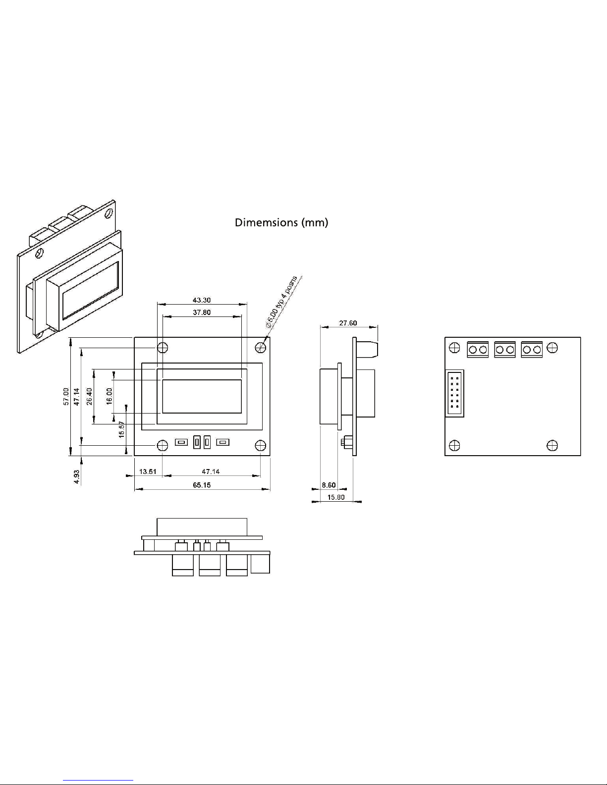
Dimemsions (mm)
 Loading...