

Page 1
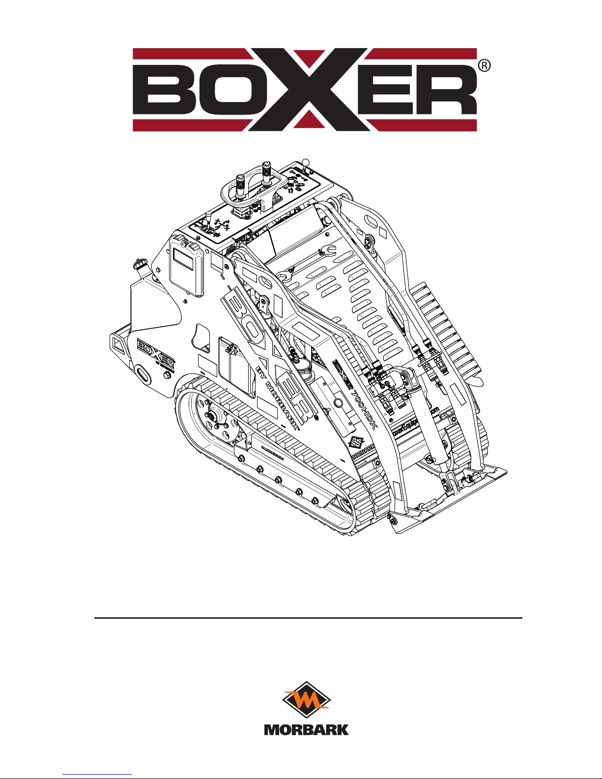
Serial No.s 5121 and Higher
Part No. 76347-314
Manufactured by:
700HDX Operator’s Manual
Phone: Morbark®, LLC.
Sales - 800-831-0042 8507 S. Winn. Rd., P.O. Box 1000,
Parts and Service - 800-255-8839 Winn, Michigan 48896
www.boxerequipment.com www.morbark.com
BIG POWER IN ALL PLACES
®
Page 2
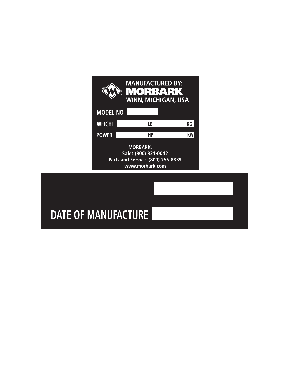
Your machine’s Model, Weight, and Power Rating along with Serial Number and Date of
Manufacture of your machine are located on the right side panel at the top.
The Engine information is located on a decal on your engine. Refer to your Engine OEM
Manual for decal location.
®
39510-475
700HDX
2660
1206.7
25
18.64
LLC
SERIAL NO.
39510-154
XXXX
00-00-0000
Page 3

III
Page 4

IV
Morbark, LLC.
8507 South Winn Road, P.O. Box 1000, Winn, Michigan 48896
Phone: Sales - 800-831-0042,
Parts and Service - 800-255-8839
www.morbark.com
LIMITATION OF DAMAGES
City: ___________________ State/Province: __________ Zip/Postal
Code: ________________________
Phone: ________________ E-mail address: ___________________
_____________________________
Model No.________________ Serial No._______________
Engine S/N: ________________________
Location Purchased: _____________________________ Date
Purchased: _______________________
I, (the purchaser), have read and fully understand the operator’s manual, safety instructions and warranty conditions provided with this
equipment.
In-service date restart will only be accepted if this form and a copy
of the bill of sale is completed and returned within 30-days of the inservice date.
Customer Signature: _______________________________________
_ Date: ____________________
Product Description
Morbark
Manufactured
Components
Vendor Purchased
Components
Extended Coverage
New Boxer Compact
Utility Loaders
One (1) year/1,000
hours; whichever comes
rst
Warranty from vendor
applies, minimum of one
(1) year
Can purchase prior to
start-up
Used Equipment As stated on equipment
order
N/A N/A
New Engines N/A See Engine Warranty
Statement
Can purchase prior to
start-up or possibly up to
two (2) years after startup depending on the
programs offered by the
engine supplier
Wear Items including
but not limited to such
items as, lubricants,
anti-freeze, uids, lters,
belts, bearings, hoses
and ttings, etc…
Manufacturer’s limited
warranty extended to
the original purchaser to
cover conditions that are
reasonably considered
to have been within the
manufacturer’s control.
Conditions not within the
manufacturer’s control
such as irregular wear,
lack of maintenance,
damage due to accidents
or vandalism are not
covered.
Manufacturer’s limited
warranty extended to
the original purchaser to
cover conditions that are
reasonably considered
to have been within the
manufacturer’s control.
Conditions not within the
manufacturer’s control
such as irregular wear,
lack of maintenance,
damage due to accidents
or vandalism are not
covered.
N/A
Page 5

V
Boxer® Warranty Registration
Dear Customer,
Morbark, LLC., manufacturer of the Boxer® Compact Utility Loader, would like to thank you for
your purchase. Morbark is committed to providing unsurpassed products and product support to
our customers. To accomplish this, we need to update our database with information regarding your
purchase. Currently, the warranty start date (in-service date) is listed as the date the Boxer® Compact
Utility Loader left Morbark, LLC., which may be several months before you received and placed your
new Boxer® product into service.
To ensure you get the full warranty coverage for your purchase, Morbark, LLC. will restart the warranty
start date (in-service date) if you complete the information below and return this form to us with a copy
of the equipment invoice (bill of sale) verifying the in-service date of your Boxer® Compact Utility
Loader. Without receipt of this form, we will continue to use the original equipment ship date
as the warranty start date (in-service date) and not returning this form may result in denial of warranty
entitlements.
To restart the equipment in-service date, simply complete the form below and mail, e-mail, or fax the
completed form and bill of sale to:
Morbark, LLC.
P.O. Box 1000
8507 S. Winn Road
Winn, MI 48896-1000
E-mail: [email protected]
Fax: (989) 866-2280
Fold
Company Name: ________________________________ Contact Name: ________________________
Address: ____________________________________________________________________________
City: ___________________ State/Province: __________ Zip/Postal Code: ____________________
Phone: ________________ E-mail address: ____________________________________________
Model No.________________ Serial No._______________ Engine S/N: ____________________
Location Purchased: ____________________________ Date Purchased: _______________
I, (the purchaser), have read and fully understand the operator’s manual, safety instructions and
warranty conditions provided with this equipment.
In-service date restart will only be accepted if this form and a copy of the bill of sale is completed
and returned within 30-days of the in-service date.
Customer Signature: ______________________________________ Date: ___________________
Page 6

VI
Morbark, LLC.
8507 South Winn Road
P.O. Box 1000
Winn, MI 48896
Afx
Stamp
Here
Page 7

VII
Safety Introduction
Be Prepared - Get to Know All Operating and Safety Instructions
This is the Safety Alert Symbol.
Wherever it appears, either in this manual or on safety signs on the machine, you should be
alert to the potential for personal injury or accidents. Always observe safety precautions and
follow recommended procedures.
Learn the Signal Words Used with the Safety Alert Symbol
The words “DANGER”, “WARNING”, and “CAUTION” are used throughout this manual
and on labels on the machine to indicate hazards or unsafe practices. All three statements
indicate that safety is involved. Observe the precautions indicated whenever you see the
Safety Alert symbol no matter which signal word appears next to the Safety Alert symbol.
INDICATES A HAZARDOUS SITUATION THAT, IF NOT AVOIDED, IS VERY
LIKELY TO CAUSE DEATH OR EXTREMELY SERIOUS INJURY. IT MAY
ALSO BE USED TO ALERT AGAINST EQUIPMENT THAT MAY EXPLODE OR
DETONATE IF HANDLED OR TREATED CARELESSLY.
Indicates a hazardous situation that, if not avoided, could result in serious injury or
death. It may also be used to alert against a highly unsafe practice.
Indicates a hazardous situation that, if not avoided, could result in minor or moderate
injury. It may also be used to alert against a generally unsafe practice.
This type of statement is used to draw attention to a procedure that needs to be followed to
prevent machine damage.
DANGER
WARNING
CAUTION
NOTICE
Page 8
VIII
REVISION LOG
Rev: Rev. Date:
Pages
Affected:
Description
of Changes:
- Jan 20, 2017 All Initial Release
Page 9

IX
Table of Contents
Boxer Product Warranty ..................................................................................iv
Safety Introduction .......................................................................................... vii
Be Prepared - Get to Know All Operating and Safety Instructions ...... vii
Learn the Signal Words Used with the Safety Alert Symbol ................ vii
Section 1 – Safety Precautions ....................................................................1–1
General Safety .......................................................................................... 1–1
Operating Safety ....................................................................................... 1–2
Service & Maintenance Safety..................................................................1–4
Electrical System Hazards ........................................................................ 1–4
Battery Hazards .................................................................................1–5
Jump Starting/Battery Charging Hazards ..........................................1–5
Hydraulic System Hazards .......................................................................1–6
Fueling Hazards........................................................................................1–7
Section 2 – Operating Controls .................................................................... 2–1
Component Locations ............................................................................... 2–1
Left Front View ...................................................................................2–1
Right Rear View .................................................................................2–2
Safety Decals ..................................................................................... 2–3
Operating Controls ............................................................................. 2–5
Operating Controls Description .......................................................... 2–6
Section 3 – Pre-Start Inspection and Operation ......................................... 3–1
Pre-Start Inspection .................................................................................. 3–1
Daily Service Checks ................................................................................ 3–1
Cylinder Lock Installation .......................................................................... 3–9
Cylinder Lock Removal ...................................................................... 3–9
Operating Instructions.............................................................................3–10
Machine Start-up .............................................................................3–10
Machine Shut-down ......................................................................... 3–11
Transportation ..................................................................................3–12
Lifting Procedures ............................................................................ 3–13
Machine Travel Controls .........................................................................3–14
Attachment Installation and Removal .....................................................3–18
Attachment Lock Pins ......................................................................3–18
Installation of Non-Hydraulically Powered Attachments ..................3–19
Removal of Attachment ....................................................................3–21
Installation of Hydraulically Powered Attachments ..........................3–21
Operating Instructions for a Hydraulic Attachment ..........................3–26
Removal of Hydraulically Powered Attachments .............................3–29
Page 10

X
Section 4 – Routine Service and Maintenance ...........................................4–1
Daily Maintenance Procedures ................................................................. 4–2
New Machine Brake-in Maintenance Procedures ..................................4–14
Weekly Maintenance Procedures ...........................................................4–15
Monthly Maintenance Procedures ..........................................................4–16
Annual Maintenance Procedures ...........................................................4–20
General Maintenance .............................................................................4–22
Draining Fuel Tank (Diesel) ..............................................................4–22
Fuse Panel ....................................................................................... 4–24
Track and Tension System Installation ............................................4–26
Section 5 – Troubleshooting ........................................................................5–1
Section 6 – General Specications .............................................................. 6–1
Page 11

1.1
Section 1 - Safety Precautions
Since Morbark LLC. has no direct control over machine application or operation, following
the proper safety practices is the responsibility of the owner and/or operator. Remember that
this unit is only as safe as those who operate it. Safety practices described throughout this
Operator’s Manual must be followed at all times.
GENERAL SAFETY
• Never operate the Boxer without first completely reading and understanding this Owner’s
Manual.
• Only authorized, qualified, and trained personnel are allowed to operate this machine.
• Never operate the machine under the influence of alcohol, awareness altering drugs or
medications that would affect your ability to operate safely.
• KEEP CHILDREN CLEAR FROM THE WORK SITE AREA AT ALL TIMES!
• NEVER ALLOW A CHILD TO OPERATE OR RIDE ON THE MACHINE!
• Serious injury or death involving children can occur. Stay ALERT and be aware of your
surroundings at all times. Stop operations if children wander onto the job site. Resume
work only when the operating area is clear.
• Keep all non-operating personnel away from the machine during operation.
• Passengers must never be allowed to ride on the machine or any attachment.
• Wearing protective clothing and gear, such as hard hats, safety glasses, safety shoes,
hearing protection, breathing protection, and long pants and shirts is highly recommended.
Do not operate in clothing or shoes which will expose skin or feet to possible flying debris.
• Clothing should be relatively close fitting. Loose clothing, rings, and other jewelry should
be avoided because of the danger of catching them on machine parts or controls or on any
rotating parts, either on the machine or any attachment.
• Keep hands/fingers clear from all rotating parts.
• Never touch engine parts or machine components while they are hot.
• Always perform the “Standard Shut Down Procedure” shown in this manual, if the unit
will be left unattended for any length of time.
• Use only original Morbark or approved replacement parts and attachments. Imitation parts
may lead to unit damage and/or injury to personnel. The machines warranty may be voided
if unauthorized parts and attachments are used.
Page 12

Safety Precautions
1.2
OPERATING SAFETY
• Plan ahead and learn as much as possible about your job-site area before beginning any
work.
• Know the exact location of overhead power lines or obstructions.
• Have all buried lines such as gas, electric, water, telephone, and cable TV marked by the
proper authorities.
• Prior to use, perform the “Pre-Start Inspection” and Daily Maintenance to make sure that
the unit is in safe operating condition.
• Never operate a malfunctioning unit.
• Keep hands, gloves, shoes, control knobs, and operator platform clean. Slippery controls
can cause you to lose control, which may result in an accident.
• Always keep a firm grip on the hand rails located at the operator’s platform during travel
and operation to prevent falling off the unit.
• When working on an unfamiliar construction site, review, understand, and follow job site
safety rules.
• Keep the work site clear of all non-operating personnel. Should a person enter the work
area, stop machine operation until the work area is clear.
• Prior to unloading the unit and starting to work, inspect the path you will travel and work
site area for potential hazards. Some of the hazardous conditions you may encounter are:
- Holes
- Deep ditches or excavations
- Drop-offs
- Soft un-compacted soil
- Culverts
- Deep mud/Standing Water
- Large rocks
- Slippery surfaces
- Steep slopes
- Tall grass, trees or shrubs
If any of these conditions exist, correct the hazard or obstruction. If any of these conditions
can not be corrected, avoid operating or traveling near them.
• Be extremely cautious traveling through or near trees, brush, shrubs or any obstacles which
might obscure your vision. These might hide potential hazards, such as the edge of a steep
slope, deep holes, large rocks, etc.
• Never operate near a ditch or embankment where loose or soft ground conditions could
cause the surface to give way under the machine causing it to become unstable.
• Never exceed the rated capacity of the machine. When using attachments, know their
capacity ratings and unit limitations. Unit specifications can be found in the Operator’s
Manual.
Page 13

Safety Precautions
1.3
• Never attempt to operate any attachment without first understanding proper installation
and operating procedures. The center of gravity, stability, and operating characteristics of
the entire machine will change with the use of different attachments.
• Operate all controls slowly and smoothly and never abruptly stop any function. This can
cause the machine to become unstable.
• Always look in the direction of travel.
• Come to a complete stop prior to reversing travel directions.
• Reduce speed and proceed with caution when traveling in reverse or turning.
• Never travel with the loader boom or attachment raised. Lower the boom or attachment as
soon as possible and travel with the boom at the lowest safe height.
• When traveling with a loaded bucket or forks, the load should be level and the bucket or
forks tilted back to reduce spilling or losing the load.
• Approach corners slowly, turning too fast or sharp may cause the machine to tip over.
• Stay alert when operating near traffic or roadways.
• If the unit should begin to tip or become unstable, DO NOT try to stabilize the unit with
your legs or arms.
• If the unit is involved in an accident or inadvertently damaged during operation, stop and
perform a thorough inspection. Make sure the unit is in safe operating condition prior to
resuming work.
• Be alert to any unusual reaction to any of the controls. If anything unusual is noticed, shut
the machine down and thoroughly inspect it to determine the cause of the problem. Do not
operate the machine until all required repairs have been made.
• If the unit must be left unattended, shut the machine down and make sure that it can not be
started by an unauthorized individual.
• Operating on steep slopes can be dangerous and there is a greater risk of the machine
tipping over or becoming unstable. The list of rules below must be understood and
followed for maximum safety:
- Avoid excessively steep slopes or unstable surfaces. If travel on a slope is necessary,
keep the load low and proceed with extreme caution.
- DO NOT travel ACROSS excessively steep slopes under any circumstances.
- Travel straight up and down slopes with the heavy end of the machine pointing up the
incline. When the machine has no load, the operator’s platform end of the machine is
considered the heavy end. When the machine is loaded or has an attachment on the front
of the machine, the front is considered the heavy end.
- Turning on slopes is not a recommended practice, however if you must turn on slopes;
reduce travel speed to as slow as possible, and exercise extreme caution. Avoid sharp
turns or sudden movements.
- Wet or slick ground conditions should be avoided as reduced traction could cause the
machine to slide down the slope.
- Do not attempt to install or remove attachments on a slope.
- Never park the unit on a slope.
Page 14

Safety Precautions
1.4
SERVICE & MAINTENANCE SAFETY
Maintenance work can be hazardous if not done in a careful manner. All personnel should
realize the hazards and strictly follow safe maintenance practices. Failure to comply with
these safety precautions may result in serious personal injury and/or death.
• Use only Morbark supplied or approved replacement parts and attachments. Imitation
parts may lead to unit damage and/or injury to personnel. Warranty may be voided if
unauthorized parts and attachments are used.
• Wear the proper protective clothing and personal safety equipment necessary to perform
the maintenance or service required.
• Keep the machine free of grass, leaves or other debris build-up.
• Clean up oil or fuel spillage.
Fuel, oil leaks or spills can create a re or explosion hazard.
• Prior to performing maintenance or service, park the unit in a level area away from
obstructions and/or work site hazards.
• Be sure the area has adequate light and is well ventilated. NEVER operate the machine
inside a closed area.
• Clean-up any oil, grease, mud, water or snow which might cause the floor surface to
become slippery.
• If the machine requires maintenance, take the machine out of service and attach a “Do Not
Operate” tag at the control panel and remove the ignition key.
• If maintenance or repairs require the boom to be raised, the “Hydraulic Cylinder Lock”
must be installed.
• Know where all pinch points and rotating parts on the unit are. These areas must be
avoided to prevent serious injury.
• Remove only those guards or covers on the component being serviced and replace them
immediately upon completion of the work.
• Never attempt to adjust or service engine or machine components while they are hot.
ELECTRICAL SYSTEM HAZARDS
• Prior to working on the electrical system:
- Disconnect battery cables, removing the battery ground cable rst.
- When re-connecting the battery, connect the battery ground cable last.
- Never allow battery cables to contact hydraulic lines or rub against sharp edges.
WARNING
Page 15

Safety Precautions
1.5
Battery Hazards
Before working with batteries, the following are important points about battery safety that
you should be aware of:
• Batteries are always surrounded by extremely explosive gases. This is especially true when
the battery is being charged. To avoid explosion:
- Do not smoke near batteries.
- Keep arcs, sparks, and open ames away from batteries.
- Perform battery service work only in a well ventilated area.
• Make sure to dispose of batteries according to local regulations.
• Electrolyte Hazards:
NOTE: The batteries on the machine may be either be “wet cell” or gel cell. It is still
important to know and follow these warnings and cautions.
Battery electrolyte in standard “wet cell” batteries contains sulfuric acid which is poisonous
and can cause severe chemical burns. To avoid personal injury:
- Wear a face shield to prevent sulfuric acid contact with your eyes.
- Wear chemical resistant gloves and clothing to keep acid off your skin and clothing.
- Since “wet cell” batteries give off explosive gases, use a ashlight to check the
electrolyte level, not an open ame such as a match.
- Never check the battery by placing a metal object across the battery posts. The resulting
spark could ignite anything ammable, causing re or an explosion.
- If electrolyte is splashed into your eyes, ush them immediately with clean water and
seek medical attention.
- If electrolyte is swallowed, seek medical attention immediately.
- If electrolyte is splashed onto exposed skin or clothing, ush and clean the area
immediately with clean water and seek medical attention if necessary.
Jump Starting/Battery Charging Hazards
Follow the instructions for jump starting or battery charging in the engine owner’s manual.
You must be at the operator’s platform when attempting to start the unit with booster batteries
and jumper cables so that you are at the controls when the engine starts.
Here are some general safety rules you must follow for jump starting the machine:
• Make sure to connect the positive jumper cable to the positive post of the battery.
• Connect the negative cable to the engine, machine chassis or the furthest ground point
away from the battery. Never make the final connection at the starter or dead battery.
Sparks may ignite the explosive gases surrounding the battery.
• When disconnecting cables after jump starting, remove the negative cable first and then
the positive cable. NOTE: DO NOT let the cable clamps touch when disconnecting them.
Severe damage can occur to the booster battery or machine.
• Never charge a battery or attempt to jump start a frozen battery. The sudden surge in
electrical power could cause the battery to explode.
Page 16

Safety Precautions
1.6
Hydraulic System Hazards
The hydraulic system is under pressure whenever the engine is running and may hold
pressure even after the engine is shut off. Cycle all hydraulic controls after the loader boom
is resting on the ground. Some components will retain residual or trapped pressure. Use
extreme caution when removing any hydraulic component.
During inspection of the hydraulic system:
• Cycle all hydraulic controls to release residual pressure.
• Wait for the hydraulic fluid to cool down before disconnecting any hydraulic lines. Hot
hydraulic fluid can cause severe burns.
Hydraulic oil under pressure can penetrate body tissue causing serious injury and
possible death. When troubleshooting a hydraulic system for leaks, always use
cardboard or wood as a detector. DO NOT USE YOUR BARE HANDS. If you are
injected with hydraulic oil or any other uids, immediately seek treatment by a doctor
trained in the treatment of penetrating uid injuries.
• Hydraulic system, loosen the filler cap slowly to allow any pressure in the hydraulic tank
to be reduced. Hydraulic fluid can cause permanent eye injury. Wear safety glasses or a full
face shield to provide appropriate eye protection.
• When venting or filling the hydraulic tank, loosen the filler cap slowly to allow any
pressure in the hydraulic tank to be released and remove the cap gradually.
WARNING
Page 17

Safety Precautions
1.7
Fueling Hazards
Most fuels are highly ammable. Observe the following precautionary practices to reduce the
possibility of a serious accident:
• Always refuel the unit in an open, well ventilated area away from sparks or open flames.
Diesel Engines:
• Shut the engine off before attempting to fuel the machine. Never refuel a unit
while it is running.
• Allow engine to cool before re-fueling.
• Always use a funnel or pour spout when lling the tanks.
• Under certain circumstances a static charge can develop and ignite the fuel.
Make sure that you are standing on the ground when lling the fuel tanks.
• If you are lling the fuel tanks from a service vehicle, make sure to connect
the service vehicles ground cable to the machine before beginning the fueling
process. Keep the fuel nozzle in constant contact with the rim of the machines
fuel tank.
• When lling a portable fuel container, always place it on the ground. Never ll
a portable fuel container while it is inside a vehicle, truck, pick-up bed or any
surface.
• To avoid static sparks when using a portable fuel container, only ll the
container when it is positioned on the ground and keep the fuel container nozzle
in contact with the tank opening during lling.
• Make sure to move the unit from the transport truck or trailer and only refuel
the unit on the ground, using an approved container.
• Keep sparks and ames away from fuel.
• Do not smoke while refueling or when handling the fuel container.
• Never cut or weld on or near fuel lines, tanks or containers.
• Never overll the tank.
• Clean up spilled fuel immediately.
• Store fuel in an approved container and keep out of the reach of children.
DANGER
Page 18

Safety Precautions
1.8
Page 19
2.1
Section 2 - Operating Controls
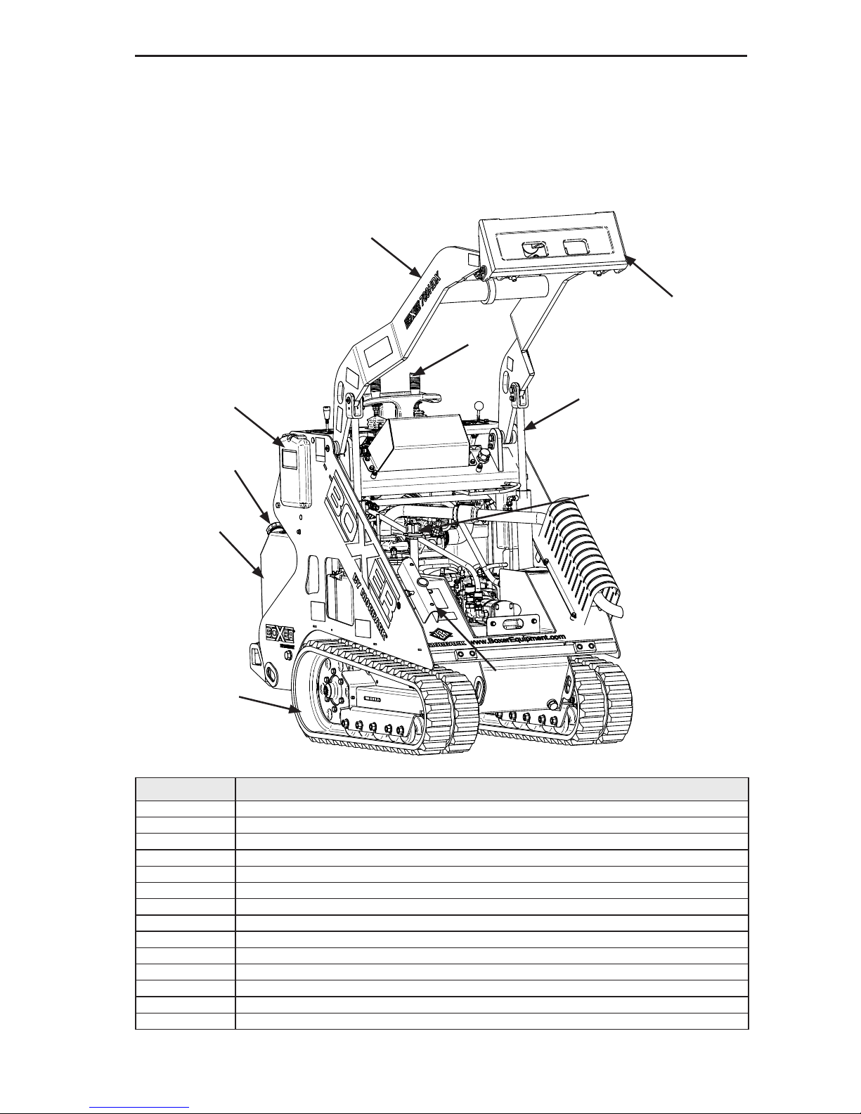
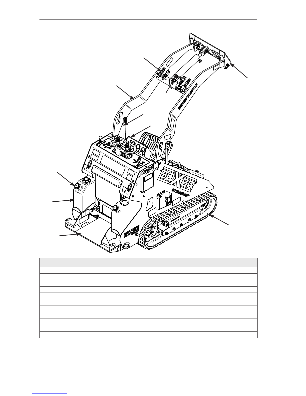
Component Locations
NOTE: FRONT PANEL REMOVED FOR CLARITY.
Left Front View
Item No. Description
1 Attachment mounting plate
2 Boom
3 Joysticks
4 Manual Holder
5 Fuel Fill Cap
6 Lift Cylinder
7 Fuel Tank
8 Right Track Assembly
9 Lift Cylinder Safety Lock
10 Hydraulic Level Check
1
2
4
5
7
8
9
10
6
3
Page 20
Operating Controls
2.2
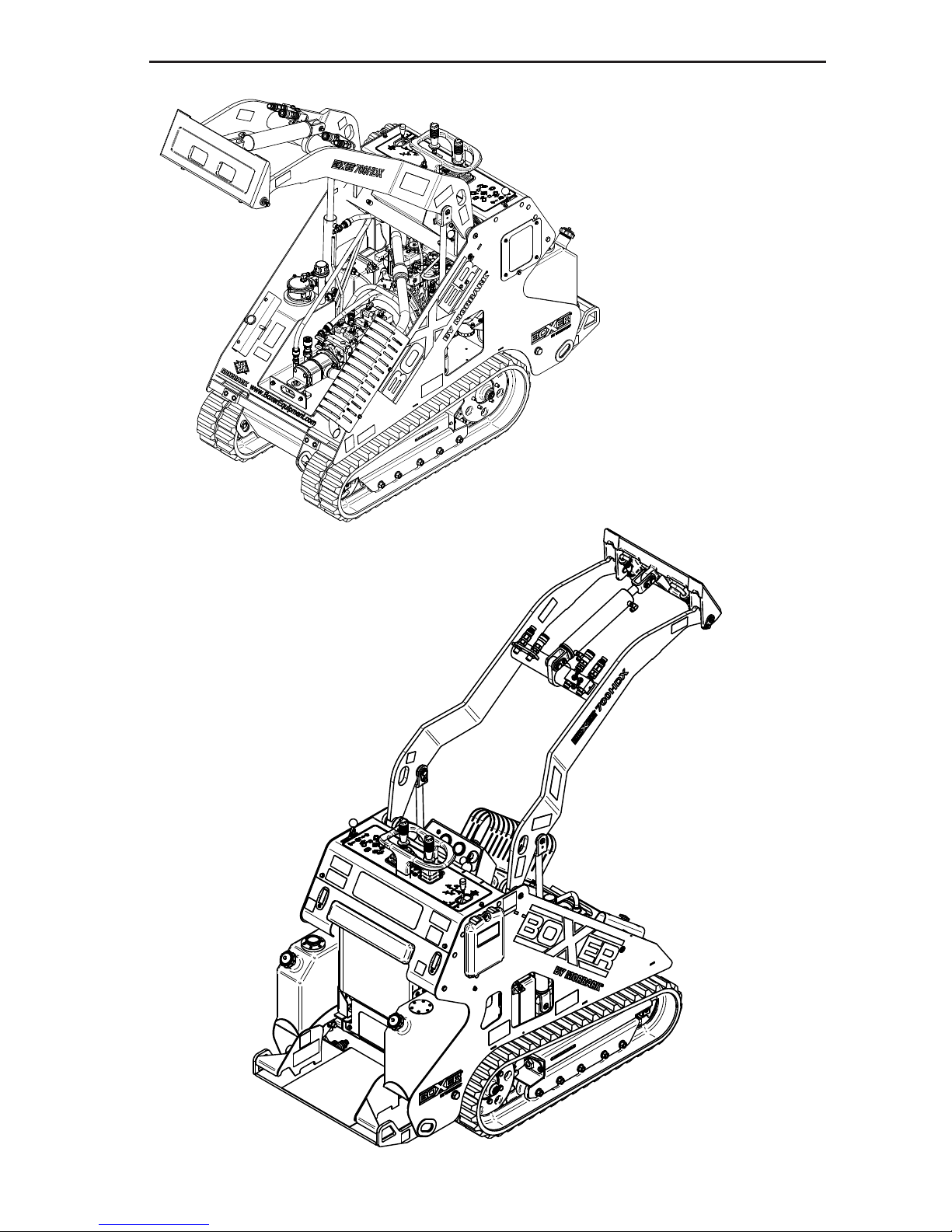
Right Rear View
Item No. Description
1 Attachment mounting plate
2 Attachment hydraulic quick connects
3 Right track assembly
4 Operator’s platform
5 Fuel tank
6 Fuel ll cap
7 Engine hour meter
8 Loader arm lift cylinder
9 Loader arms
10 Tilt cylinder
1
2
3
4
5
6
7
8
9
10
Page 21
Operating Controls
2.3
Safety Decals
Page 22

Operating Controls
2.4
Safety Decals (Continued)`
Item No. Description Quantity Part Number
1 CONTROLS DECAL 1 39510-452
2 CAUTION,BURN HAZARD/SYM CONNECT 4 39510-009
3 LIFT POINT 2 39510-004
4 “CALL BEFORE YOU DIG” 1 39510-149
5 LOCKING PIN 1 39510-018
6 WARNING,ATTACHMENT SECURE CAUTION 2 39510-013
7 WARNING,STAY BACK/SYM DANGER 2 39510-006
8 WARNING, CRUSH HAZARD/SYM DANGER 4 39510-001
9 HYD OIL,ISO PREMIUM 46 1 39510-015
10 WARNING,INSTALL CYL LOCK/SYM WARNING 1 39510-012
11 WARNING,READ MANUAL/SYM WARNING 1 39510-008
12 WARNING,BATTERY GROUND (SYM) 1 39510-007
13 NOTICE,ULTRA LOW SULFUR DIESEL 2 39510-152
14 WARNING CA PROP 65 1 39510-014
15 BOXER -LARGE 2 39510-443
16 “700HDX” DECAL 2 39510-444
17 BIG POWER DECAL 2 39510-140
18 OPERATOR CONTROLS -SAFETY- 1 39510-068
19 OPERATOR CONTROLS 1 39510-067
20 CONTROL PANEL DECAL 1 39510-070
21 BOXER INTERNET ADDRESS DECAL 1 39510-446
22 MORBARK LOGO DECAL 1 39510-145
23 TAG, MOD, WT, HP 1 39510-156
24 TAG, SN, MAN DATE 1 39510-154
25 ULTRA LOW SULPHUR DIESEL 1 39511-951
26 GASOLINE/PETROL ONLY 2 39510-002
27 TIE DOWN 3 39510-005
28 WARNING, EXPLOSION HAZARD 1 39511-952
29 WARNING, FIRE HAZARD 2 39510-011
30 SHUT OFF FUEL 1 39510-003
31 DANGER, CRUSH HAZARD 2 39510-144
32 BOXER - SMALL 2 39510-445
Page 23
Operating Controls
2.5
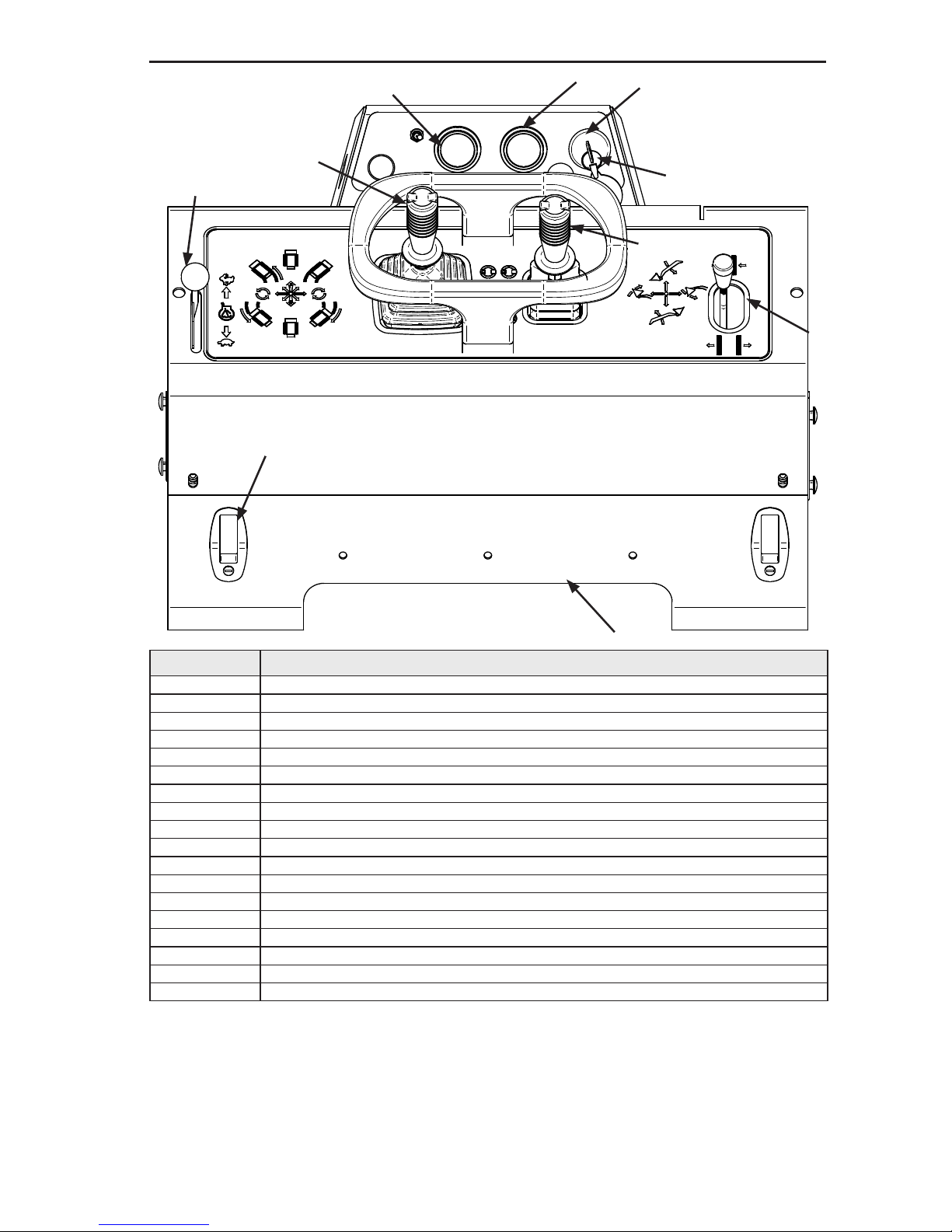
Operating Controls
Item No. Description
1 Engine coolant temperature gauge
2 Engine oil pressure gauge
3 Ignition switch
4 Ignition key
5 Track widen control
6 Right joystick
7 Left joystick
8 Engine throttle
9 Access panel Lock Levers
10 Lower service access panel
2
9
10
1
6
3
4
7
5
8
Page 24
Operating Controls
2.6
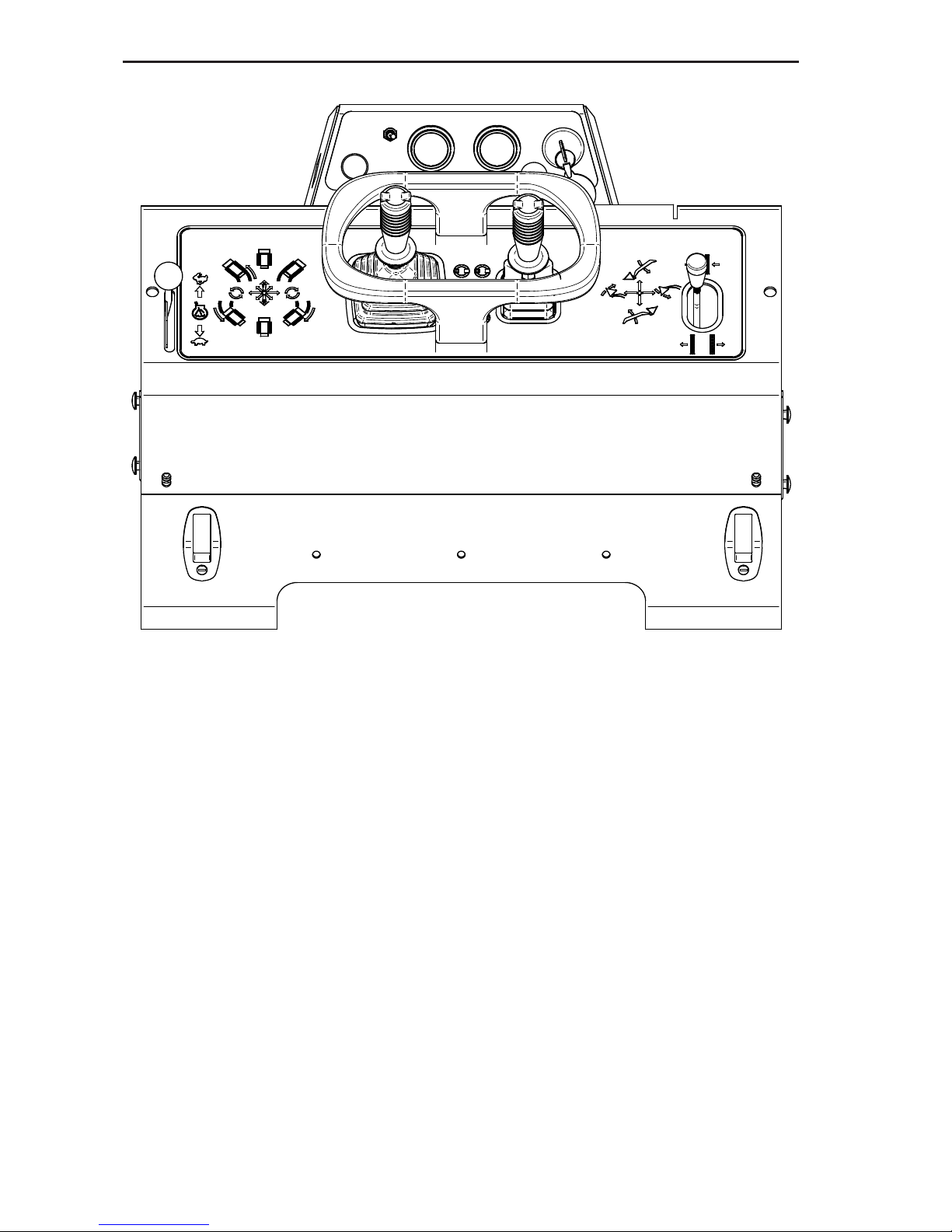
Operating Controls Description
1. Engine Coolant Temperature Gauge – Gauge indicates the temperature of the
engine coolant.
2. Engine Oil Pressure Gauge – Gauge indicates the engine oil pressure when the
engine is running.
3. Ignition Switch – Rotating the key switch to the left activates the engine glow plug.
Rotating the key switch one position to the right turns on the electrical controls.
Rotating the switch fully to the right activates the engine starter.
4. Ignition Key
5. Track Widen Control – Pushing the lever forward retracts the track. Pulling the
lever backwards widens/expands the track to the normal track width.
6. Right Joystick – Push joystick forward to lower the boom arm. Pull joystick
backwards to raise the boom arm. Push joystick to the right to tilt the attachment
to the down position. Push the joystick to the left to tilt the attachment to the up
position.
7. Left Joystick – Push the joystick straight forward to move the machine forward.
Push the joystick forward and slightly left to turn left while moving forward. Push
the joystick forward and slightly right to turn right while moving forward. Pull the
joystick straight backwards to move the machine in reverse. Pull the joystick
Page 25

Operating Controls
2.7
Operating Controls Description (cont.)
backwards and slightly right to turn right while moving in reverse. Pull the joystick back-
wards and slightly left to turn left while moving in reverse. Push the joystick directly right
to spin machine right. Push the joystick directly left to spin machine left.
8. Engine Throttle - Moving the control lever forward increases the engine speed
and moving the lever backward slows the engine speed.
9. Access Panel Lock Levers
10. Lower Service Access Panel – This panel enables access to the engine and
hydraulic controls for service procedures.
CAUTION
Page 26

Operating Controls
2.8
Page 27
3.1
Section 3 - Pre-Start Inspection and Operation
IMPROPER USE OF THE COMPACT UTILITY LOADER COULD CAUSE DEATH
OR SERIOUS INJURY. BEFORE OPERATING THE MACHINE OR PERFORMING
MAINTENANCE, THE OPERATOR MUST READ AND UNDERSTAND THE
ENTIRE OPERATOR’S MANUAL, REVIEW MACHINE CONTROLS, LOCATE
AND REVIEW ALL WARNINGS AND SAFETY PLACARDS, AND RELEVANT
OPERATOR SAFETY MATERIALS INCLUDING WRITTEN, VISUAL, VIDEO OR
VERBAL INSTRUCTIONS.
Pre-Start Inspection
It is very important to do a visual inspection of the machine before beginning operation. This
inspection should include:
• Check all decals and warning signs for damage.
• Check engine oil.
• Check and rell fuel tanks.
• Check hydraulic lines and hoses for signs of damage or leaks.
• Inspect the machine for any signs of damage or loose fasteners.
• Check uid levels and any signs of leaking uids.
• Do all Daily Service Checks.
• Check machine controls to make sure that they automatically return to the neutral
position.
The following information presents details on these inspection points and service checks
Daily Service Check and Start - Up Inspections
Service Cycle Table
DANGER
Activity Daily (10 Hours)
Fuel Check and ll
Engine Oil Check and ll if low
Engine Oil Filter Inspect for leaks
Engine Radiator Inspect add if necessary
Air Filter Check air lter dirt release
Fuel Filter Inspect for leaks
Battery Inspect terminals/leaks
Hydraulics
- Hydraulic Filter
- Hydraulic Fluid
- Hydraulic Hoses
Inspect for leaks
Check and ll if low
Inspect for leaks
Grease Check*
Track Damage Inspect
Visual Check for Loose/Missing Fasteners Inspect
Check and Adjust Track Tension Inspect
Check both Track Widening Stop Bolts Inspect
*Under very wet, muddy, dusty or dirty working conditions more frequent lubrication may be
required.
Page 28
Pre Start Inspection and Operation
3.2
Do the following pre-start service checks:
1. Check condition of all warning and instructional decals. Replace any damaged
decals with genuine Morbark replacement decals.
2. Check engine oil:
• Make sure that the engine is OFF.
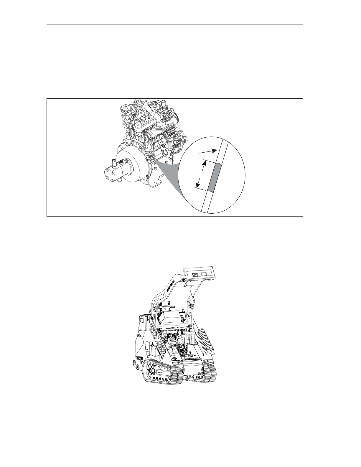
• Pull out the dipstick and look for both the full and add oil lines (Item 1, Figure 3–1)
indicated by the letters “F” and “A”. The correct oil level is between those two lines.
Figure 3-1 Engine Oil Level Check
• If the engine oil level is below the add line, indicated by the letter “A” on the dipstick,
carefully add the proper amount of oil through the engine oil ller.
It is important to add the correct type of engine oil as stated in the engine manual.
NOTE: Make sure to reinstall and secure the oil ller cap.
Figure 3-2 Filler Cap
NOTE: Extremely dusty or dirty working conditions may require more frequent
checking, lling and/or changing of engine oil.
• After lling the oil, wait a few minutes and check the oil level again.
Make sure to securely reinstall the dipstick into the dipstick tube before starting the
engine.
•
OK
x
x
x
x
x
F
A
1
Page 29
Pre Start Inspection and Operation
3.3
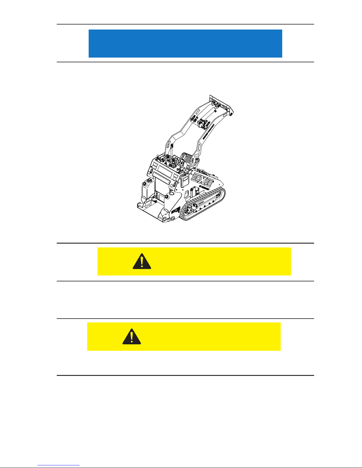
3. The Boxer has two saddle fuel tanks (Item 1, Figure 3–3). Remove cap (Item 2,
Figure 3-3) and visually inspect fuel level. Make sure that each tank has been
lled on a daily basis.
Figure 3-3 Fuel Level Check
• Carefully pour the fuel into the tank, until fuel level is at bottom of ll spout.
• Allow engine to cool before lling fuel tanks.
• Do not overll, fuel could spill onto hot engine parts and ignite or explode.
4. Check engine coolant level.
The coolant is hot and under pressure. DO NOT check until the engine radiator is cool
to the touch.
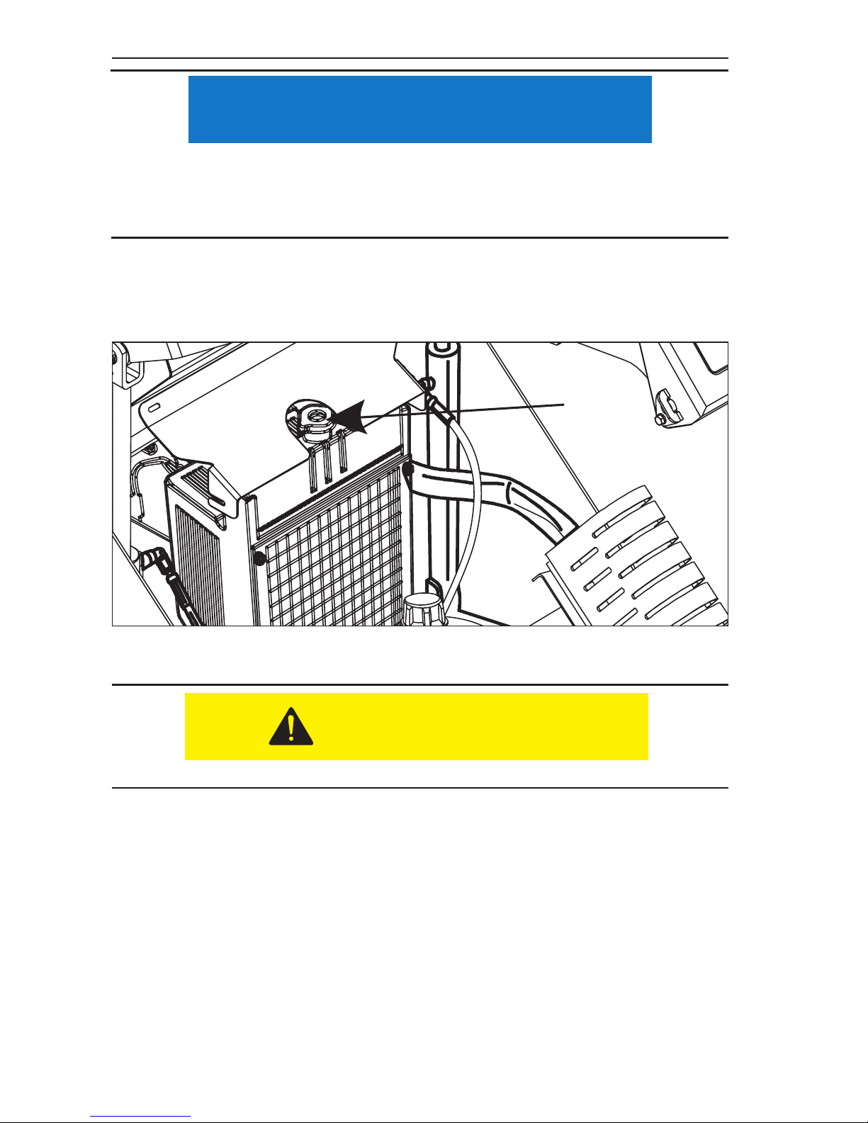
• Remove radiator cap (Item 1, Figure 3–4) and check the radiator uid level. The proper
coolant level will be to the bottom of ller neck.
CAUTION
NOTICE
CAUTION
Page 30
Pre Start Inspection and Operation
3.4
• The overow bottle is a non-pressurized container that is only for any high heat
overow. Do not add coolant to this container. It will not be drawn into the engine.
• If coolant is required, make sure to add the proper coolant as shown in the Engine
Manual.
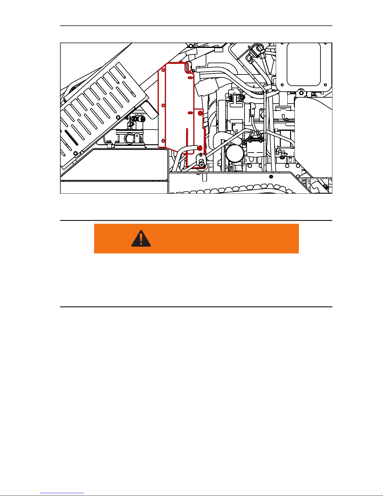
5. Inspect the radiator to make sure that the air ow is not blocked. The fan located
between the radiator and engine is a suction fan, which draws air from outside
the machine. Check radiator (Figure 3–5) to make sure that debris has not been
sucked against the radiator blocking air ow.
6.
7.
8.
DO NOT check until the engine radiator is cool to the touch.
NOTICE
Figure 3-4 Filler Cap
CAUTION
1
Page 31
Pre Start Inspection and Operation
3.5
NOTE:Some items in Figure 3–5 have been removed for clarity.
9. Check all hydraulic hoses, lines, and ttings.
Hydraulic oil under pressure can penetrate body tissue causing serious injury and
possible death. When troubleshooting a hydraulic system for leaks, always use
cardboard or wood as a detector. DO NOT USE YOUR BARE HANDS. If you are
injected with hydraulic oil or any other uids, immediately seek treatment by a doctor
trained in the treatment of penetrating uid injuries.
WARNING
Figure 3-5 Radiator Air Flow Inspection
Page 32
Pre Start Inspection and Operation
3.6
10. Check for loose or missing fasteners.
• Inspect for any loose or missing bolts.
• Tighten or replace any missing bolts immediately.
11. While you are performing the daily maintenance, inspect the machine for any
signs of damage, such as missing or damaged components, cracked welds, etc.
12. Check the track assemblies to make sure that:
• The tracks are in good condition and are not showing any signs of wear.
• Track tension is properly set.
• Track drive motors are not leaking oil or hydraulic uid.
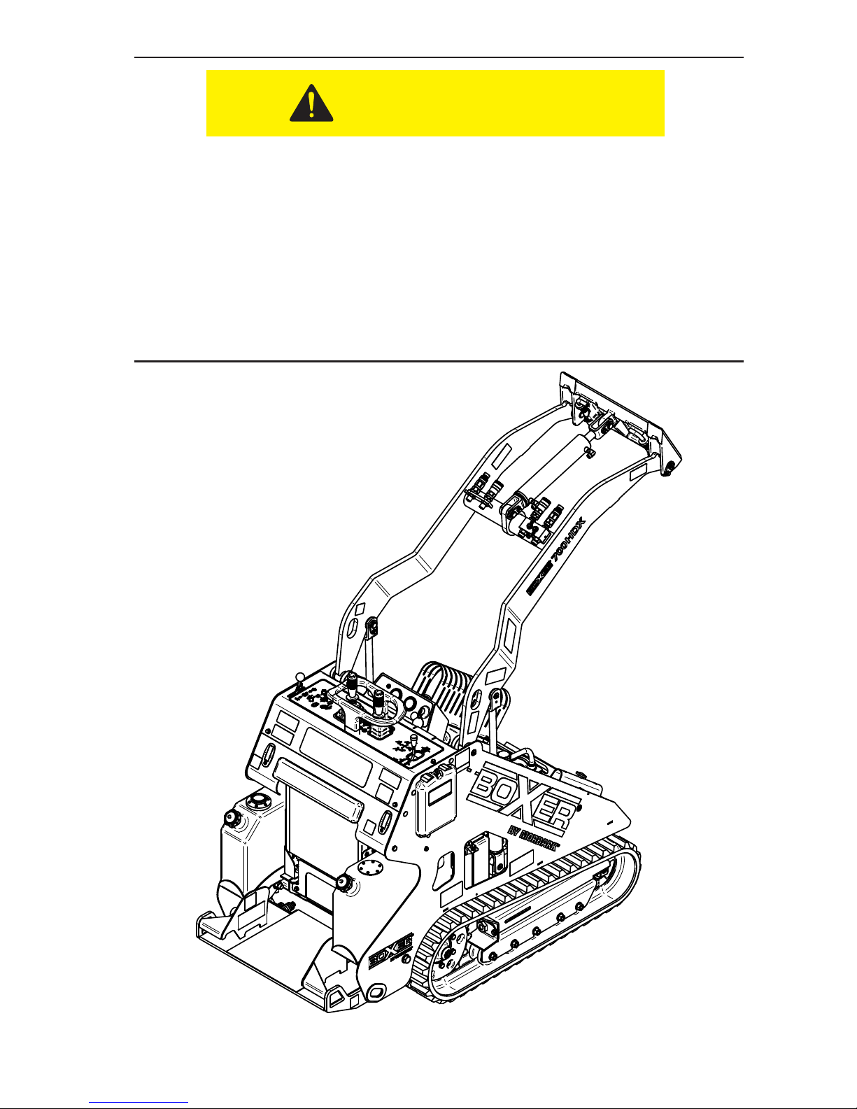
13. Grease pivot shafts with proper type of grease. There are 14 grease points on
this machine, see Figure 3–7 on page 3-7.
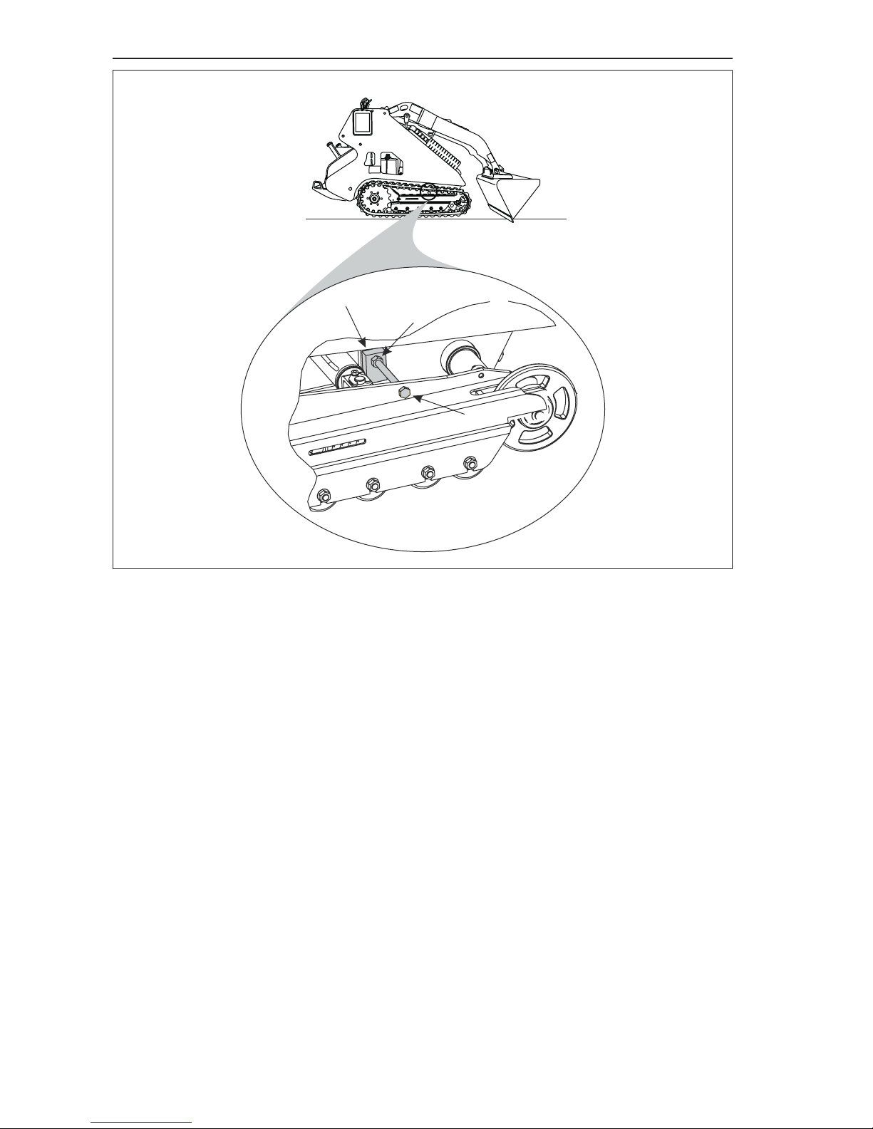
14. Inspect the Track Widening Stop Bolts, one for each track assembly, (Item 1,
Figure 3–8) for:
• Signs of wear or damage and make sure that the bolt is not loose.
• Check the widening bolt lock nut (Item 2, Figure 3–8) to make sure that it is tight
against the mounting block (Item 3, Figure 3–8).
NOTE: The lock nut, when it is fully tightened, secures the track widening stop bolt
to the mounting block.
• The track extension system has been designed to have a slight gap between the track
frame and the stop bolt head when the tracks are fully extended. If this gap is not noted,
the track widening stop bolts need to be adjusted. Refer to Section 4 for the adjustment
instructions.
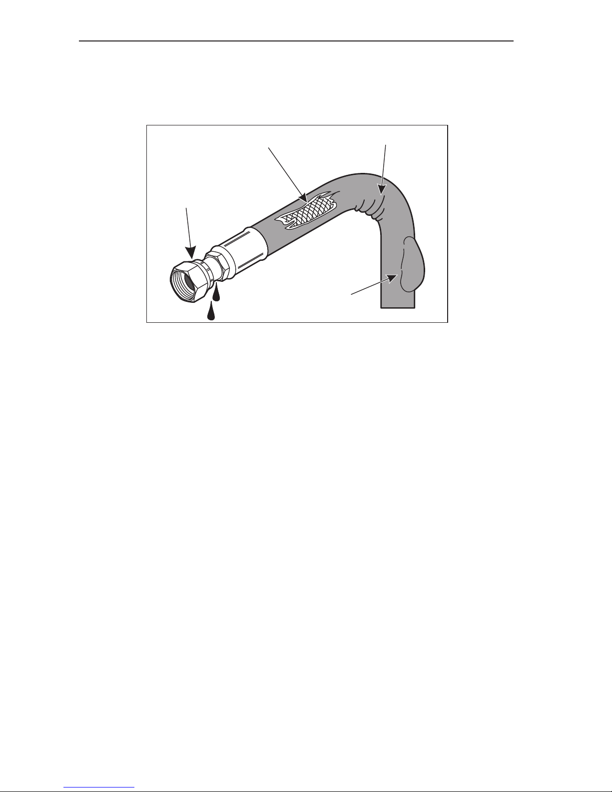
1. End ttings damaged or leaking.
2. Outer covering chafed or cut, and reinforcing wire is
exposed.
3. Hose shows signs of kinking or crushing.
4. Outer covering ballooning.
• Visually inspect all of the hydraulic hoses, lines, and ttings for signs of damage, wear
or leaking.
• If any signs of damage are visible, do not operate the machine until repairs have been
made.
• Some examples of common hydraulic hose damage are shown in Figure 3–6.
Figure 3-6 Hydraulic Hose Damage
1
3
4
2
Page 33
Pre Start Inspection and Operation
3.7
•
Figure 3-7 Lubrication Points
CAUTION
Page 34
Pre Start Inspection and Operation
3.8
Figure 3-8 Track Widening Stop Bolts
NOTE: Extremely dusty or dirty working conditions may require more frequent
service/replacement track widening stop bolts.
1
2
3
Page 35
Pre Start Inspection and Operation
3.9
1. Start the engine. (See Machine Start-up in this section for engine starting
instructions.)
2. Fully raise the loader arm.
3. Shut off the engine.
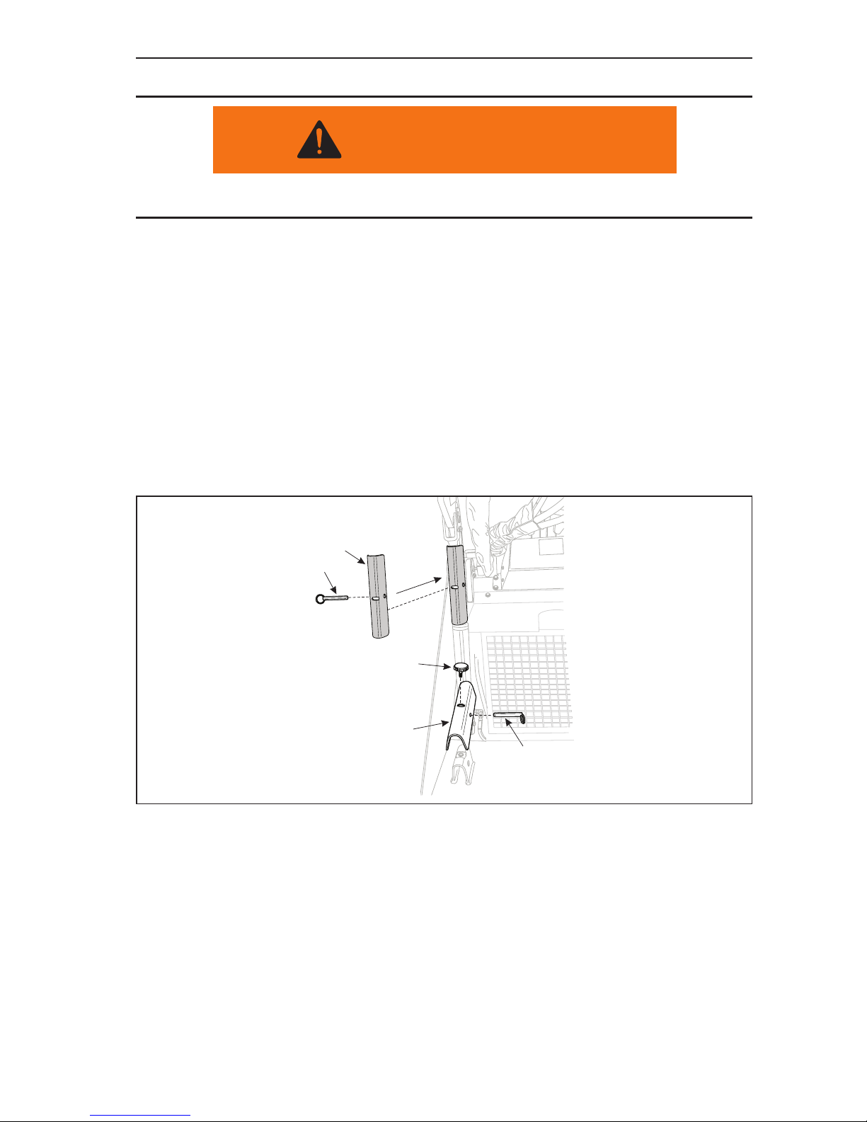
4. While holding the cylinder lock (Item 1, Figure 3–9), remove the lock knob (Item 2,
Figure 3–9) and pull the safety lock pin (Item 3, Figure 3–9) outwards, releasing
the cylinder lock.
5. Install the cylinder lock onto either of the loader arm lift cylinders.
6. Fully reinsert the safety lock pin (Item 4, Figure 3–9), securing the cylinder lock
(Item 5, Figure 3–9) in the support position.
NOTE: Make sure that the safety lock pin goes behind the loader arm cylinder.
7. Lower the loader arm assembly until it is supported by the cylinder lock.
Figure 3-9 Safety Lock Installation
Cylinder Lock Installation
Make sure to install the cylinder lock before performing any service work underneath
the raised loader arm assembly.
Cylinder Lock Removal
1. Start the engine and raise the loader arm to its full height.
2. Shut off the engine.
3. Pull the safety lock pin (Item 4, Figure 3–9) fully outwards.
4. Remove the cylinder lock (Item 5, Figure 3–9) and return it to the storage position
on one of the hydraulic lines, such as over the lter return line.
5. Fully insert the safety lock pin (Item 3, Figure 3–9) and lock knob (Item 2, Figure
3–9) to secure the cylinder lock in the storage position.
WARNING
1
2
4
5
3
Page 36
Pre Start Inspection and Operation
3.10
Operating Instructions
Machine Start-up
To start the machine, the operator must:
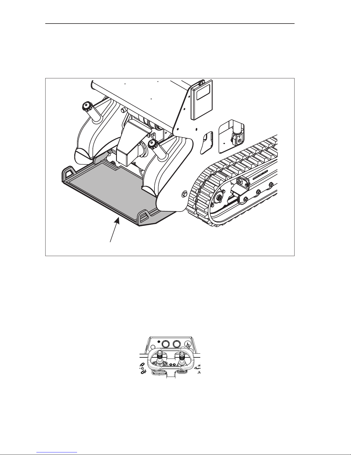
1. Stand on the operator’s platform (Item 1, Figure 3–10).
Figure 3-10 Operator’s Platform
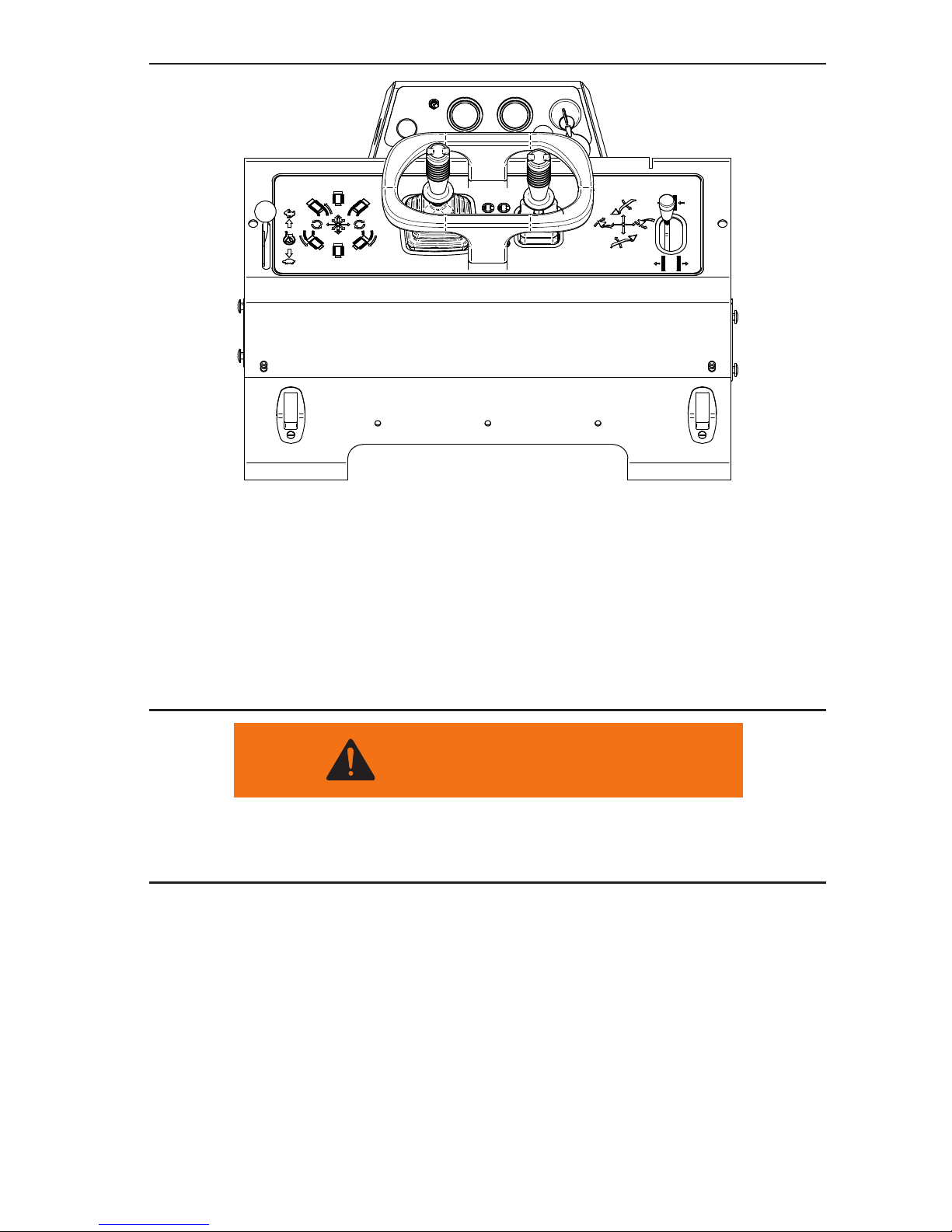
2. Rotate the ignition key switch to the HEAT position (Item 1, Figure 3–11) for about
10 seconds.
3. Move the throttle lever (Item 1, Figure 3–12) to about half way between fast and
idle engine speeds.
4. Rotate and hold the starter switch in the START (Item 4, Figure 3–11) position until
the engine starts.
Figure 3-11 Ignition Switch
1
Page 37
Pre Start Inspection and Operation
3.11
Figure 3-12 Throttle Settings
5. As soon as the engine starts, release the starter key. The key will automatically
return to the RUN position (Item 3, Figure 3–11).
6. Leave the throttle setting at about the halfway position and allow the engine to
idle. This will begin warming the engine coolant and hydraulic oil.
7. In cold weather (32º F [0º C]) after about 5 minutes of engine idling, operate all
of the main hydraulic controls to cycle warmed hydraulic oil through the hydraulic
lines into the cylinders and hydraulic motors. Allow the engine to idle for another 5
minutes before beginning any machine operations.
When warming the hydraulic oil, the operator must cycle all functions every 5 minutes.
This will assist in warming the hydraulic oil in all systems evenly and more rapidly.
Failure to do this can cause the control systems to stick creating a run-away situation.
Machine Shut-down
To safely shut the machine down, the operator must:
1. Park the machine on a solid, level area.
2. Lower the loader arm and attachment to the ground.
3. Idle the engine for 5 - 10 minutes to allow the machine to cool down.
4. Shut off the engine.
5. Clean off any accumulated mud and/or dirt from the machines operating surfaces,
operator’s platform, both track assemblies, etc.
WARNING
Page 38
Pre Start Inspection and Operation
3.12
Transportation
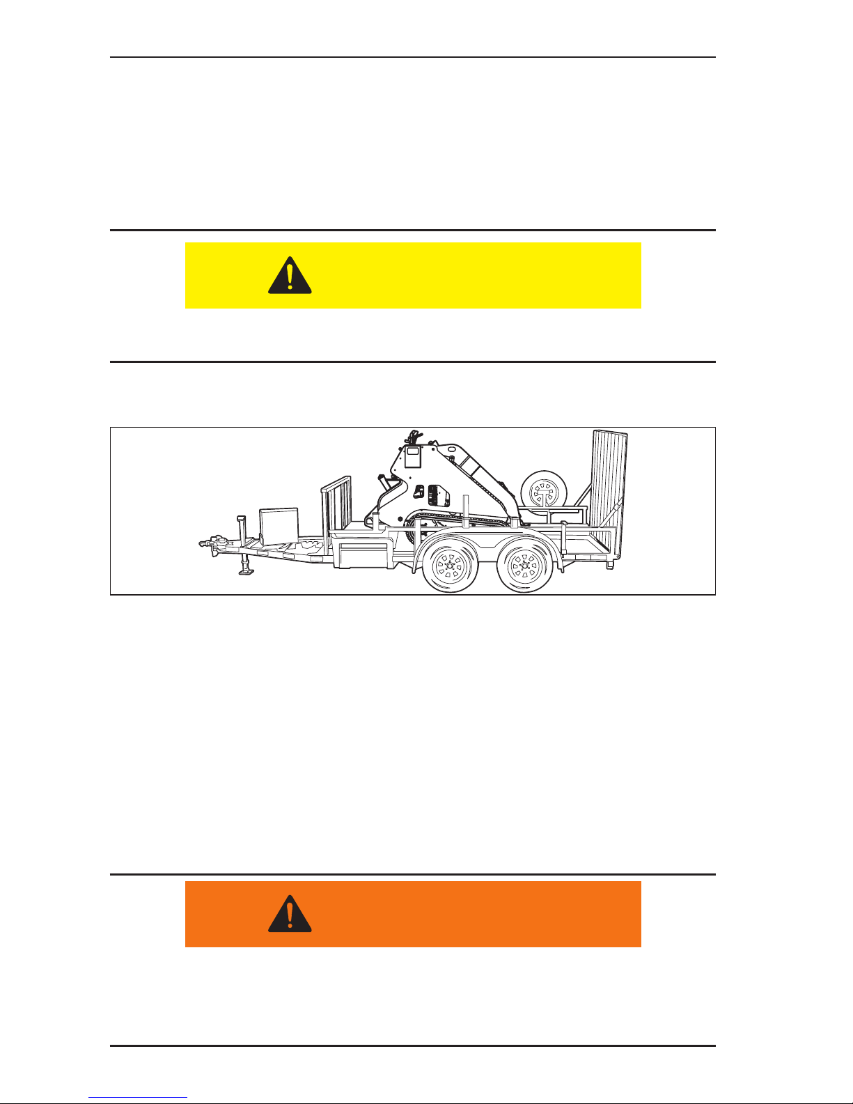
1. Move the throttle control lever to the mid-range engine speed and set the transport
speed to the LOW range. Raise the attachment so that it will clear the ramp of the
transport trailer.
NOTE: The longer the attachment, like the trencher, the more the attachment
needs to either be tilted or raised. It is recommended to back the machine onto
the transport trailer and position the machine so that the heaviest weight (center of
balance) is towards the front (hitch end) of the trailer. See Figure 3–13.
The Boxer is designed for maximum working balance. When traveling on an incline,
always have the heaviest portion of the machine pointing uphill.
2. Follow general load carrying safety. Always carry the heaviest load pointing uphill.
NOTE: When operating without an attachment, the operator becomes the load.
Figure 3-13 Transport Position on Trailer
3. When the machine is positioned on the trailer properly, lower the attachment to the
trailer deck.
4. Shut the engine off and remove the key.
5. Secure the unit to the transport vehicle with DOT (Department of Transportation)
approved chains, binders, in accordance to DOT guidelines. Make sure to use the
appropriate tie-down locations on the machine and trailer.
NOTE:
• Never tow or pull the machine. Damage to the hydraulic motors could result.
• If the machine is totally in-operable, use lifting straps or cables and a machine that can
safely lift 4,000 lbs (1820 Kg), to lift the machine and place on a trailer. Refer to “Lifting
Procedures” on page 3-13.
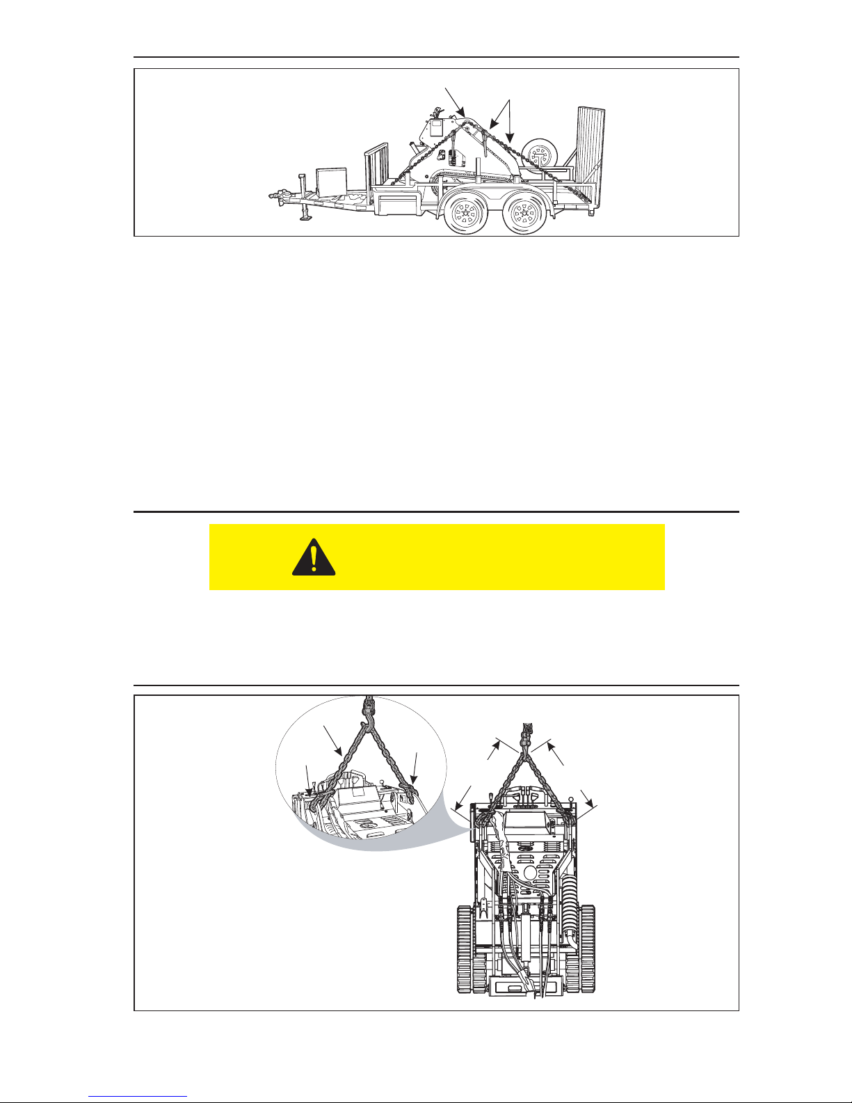
When transporting the machine, make sure to use DOT approved chains and binders
(Item 1, Figure 3–14) to secure the machine to the “D” rings on the trailer.
NOTE: It is recommended to secure the machine through the lifting holes located at the
lift cylinder end of the boom assembly (Item 2, Figure 3–14)
CAUTION
WARNING
Page 39
Pre Start Inspection and Operation
3.13
Figure 3-14 Travel Chains and Binders
Lifting Procedures
When it becomes necessary to lift the machine
1. Use a lifting device that can safely lift 4,000 lbs (1820 Kg).
2. Use appropriate lifting chains (Item 1, Figure 3–15) that can safely lift 4,000 lbs
(1820 Kg).
3. Route the chains through the lifting eyes (Item 2, Figure 3–15) located at the top
of the boom arms.
4. Make sure that the length of chain on each side of the lifting point is the same
(Item 3 A, Figure 3–15) is the same as (Item 3 B, Figure 3–15) so that the machine
is lifted straight upwards.
• Lift the machine approximately 12” to make sure that the machine is balanced
before completing the lift.
• If lifting the machine with an attachment installed, the overall machine may not
be balanced from front to back.
Figure 3-15 Machine Lifting
CAUTION
1
2
2
3 A
3 B
1
2
Page 40
Pre Start Inspection and Operation
3.14
Machine Travel Controls
• Joysticks and levers should return to the neutral position when they are released.
• Make sure that all of the levers and joysticks are in the neutral (middle) position before
starting the engine.
• Operate the levers and joysticks gradually and smoothly. Excessive speed and quick
control movements without regard for working conditions could cause an unsafe
situation.
• Make sure to maintain your grip on the hand grip area around the joysticks, any time the
machine is in motion.
Due to the spring tension system built into the track drive as a safety mechanism, the
machine can be put into an extreme situation during which the drive sprocket will bypass the
rubber track guide holes causing a popping noise, called “cogging”. This situation is part of
the track drive systems safety design and indicates that this portion of the safety system is
functioning properly.
The “cogging” condition is most likely to occur while operating in a reverse direction pulling
a heavy load and during the rst 50 hours of track usage. It is caused by the tension spring
being fully compressed due to high track load.
If a cogging condition occurs, immediately stop machine travel and auxiliary functions and
reverse travel direction slightly to de-compress track tension. Continued cogging will cause
the track drive sprocket to seat into the rubber track incorrectly, and cause damage to the
track. If cogging occurs, stop travel function and check for and remove any debris or foreign
matter in the drive system, check track for proper tension as shown in Section 4 of this
manual and resume operation.
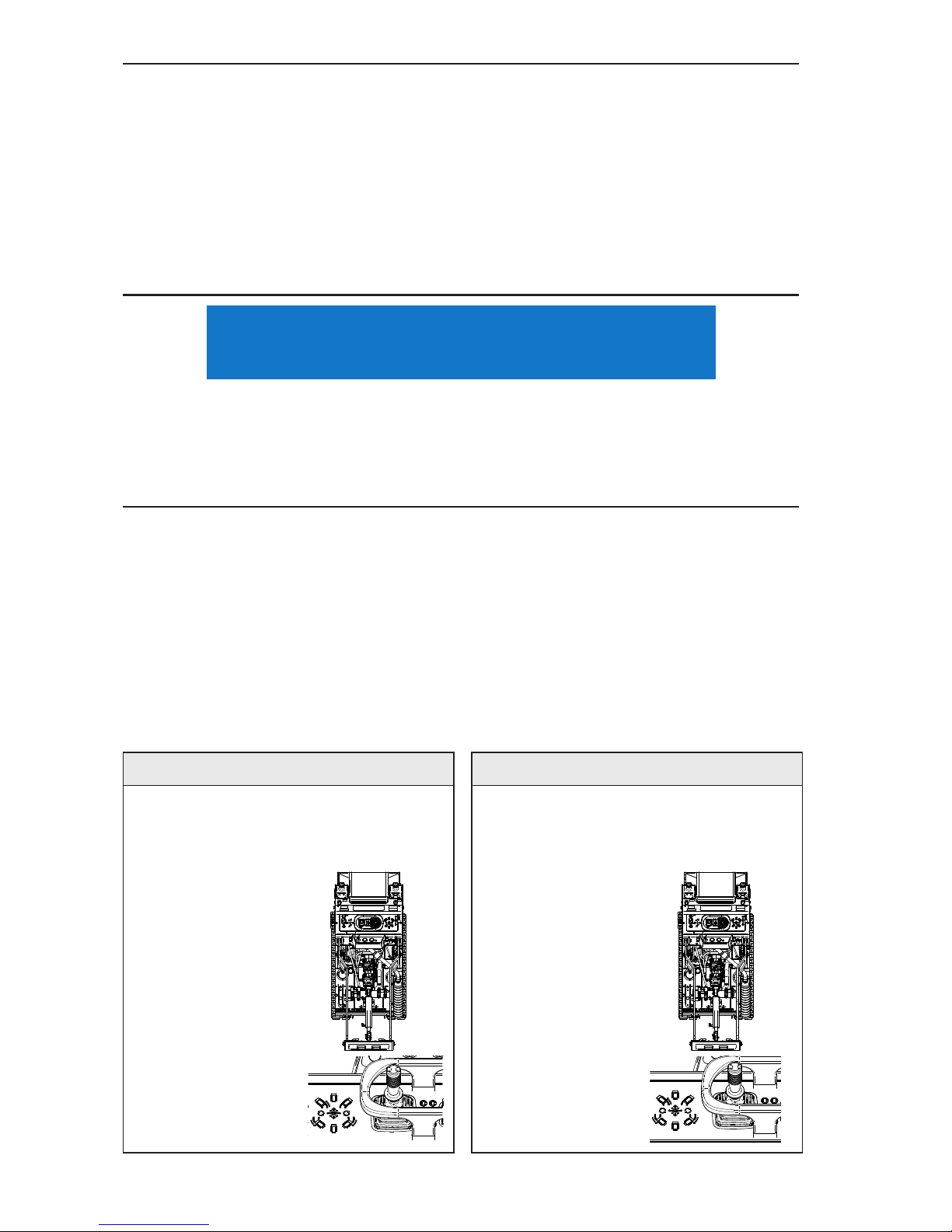
Forward Travel Reverse Travel
Push left joystick
forward to travel
straight forward.
The farther this is
moved, the faster
the machine will
travel. See Figure
3–16.
Figure 3-16
Forward Travel
Pull left joystick
backwards to
travel straight
backwards. The
farther this is
moved, the faster
the machine will
travel. See Figure
3–17.
Figure 3-17
Reverse Travel
NOTICE
Page 41
Pre Start Inspection and Operation
3.15
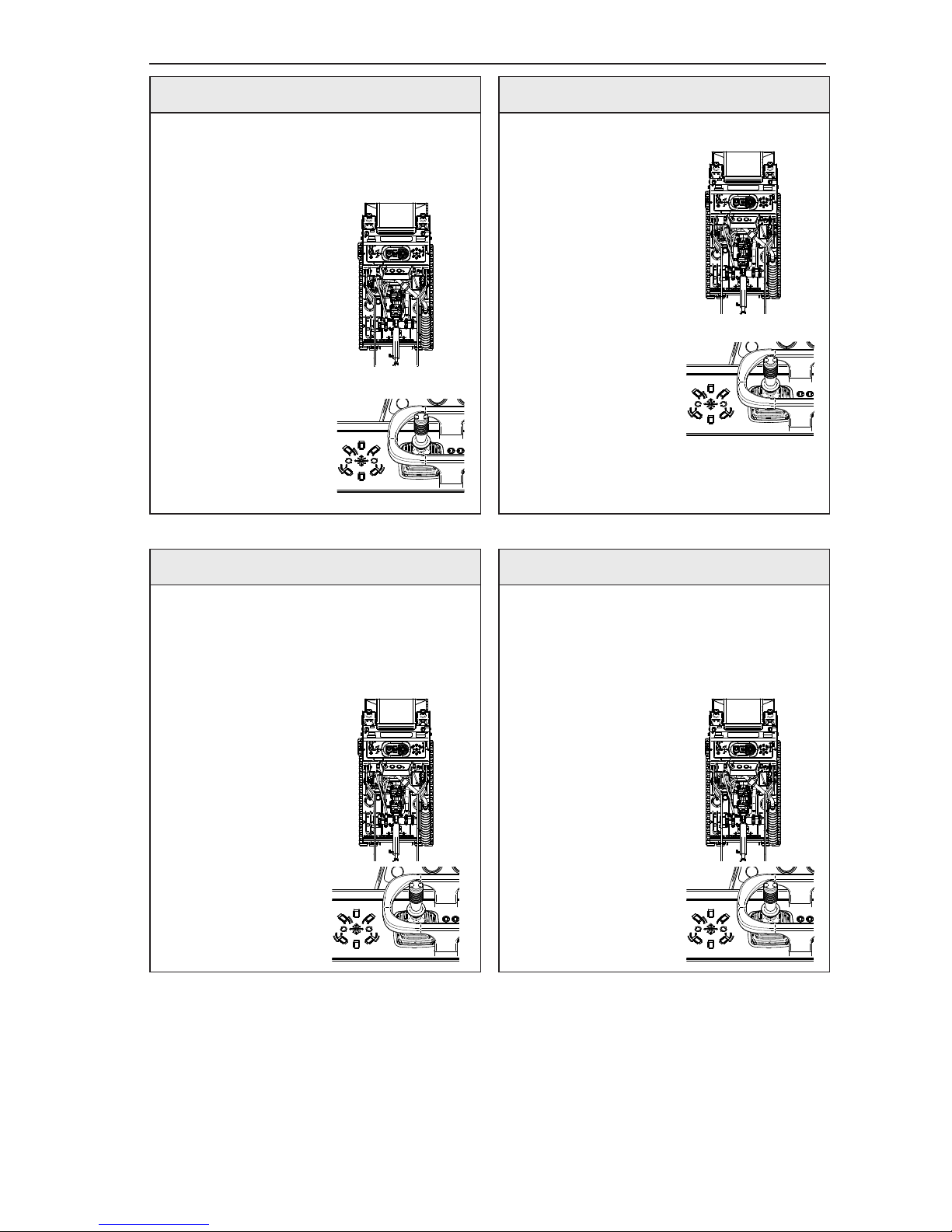
Right Turn During Forward Travel Left Turn During Forward Travel
To turn to the
right, move the
left joystick
forward and
slightly to the
right. The farther
forward and
slightly right the
joystick is moved,
the faster the right
turn will be made.
See Figure 3–18.
Figure 3-18
Right Hand Turn
in Forward
To turn to the
left, move the left
joystick forward
and slightly to the
left. The farther
forward and
slightly left the
joystick is moved,
the faster the left
turn will be made.
See
Figure 3–19.
Right Turn During Reverse Travel Left Turn During Reverse Travel
Move the
left joystick
backwards and
slightly to the
right. The farther
backwards and
slightly to the
right the left
joystick is moved,
the faster the right
turn will be made.
See
Figure 3–20.
Figure 3-20
Right Hand Turn
in Reverse
Move the
left joystick
backwards and
slightly to the
left. The farther
backwards and
slightly to the left
the left joystick is
moved, the faster
the left turn will
be made. See
Figure 3–21.
Figure 3-21
Left Hand Turn
in Reverse
Figure 3-19
Left Hand Turn
in Forward
Page 42
Pre Start Inspection and Operation
3.16
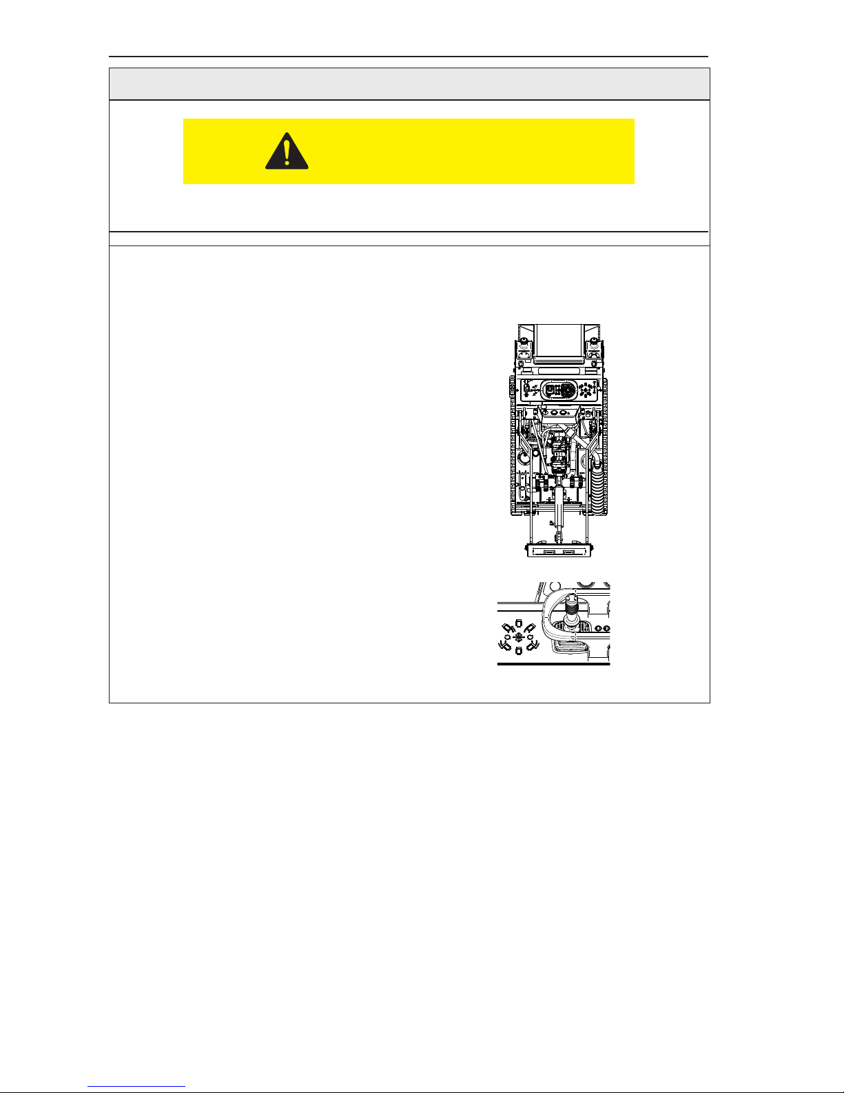
Spin Turn
Make sure to use the machine hand holds while doing a spin turn to maintain your
balance.
Move the left joystick directly to the right
to spin the machine on it axis to the right.
Move the left joystick directly to the left to
spin the machine on its axis to the left
See
Figure 3–22.
Figure 3-22 Spin Turn
CAUTION
Page 43
Pre Start Inspection and Operation
3.17
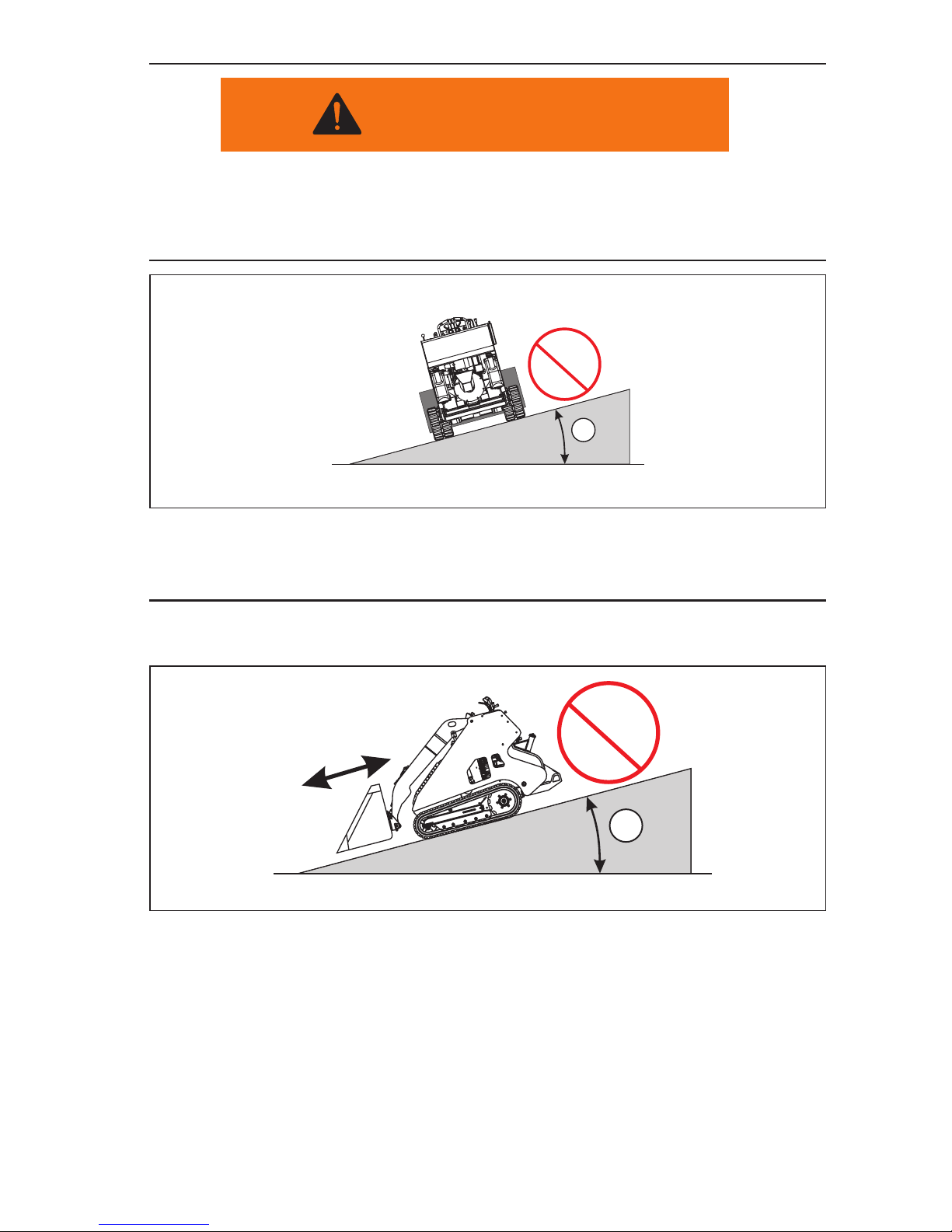
• Do not travel up or across a slope steeper than 15°. See Figure 3–23.
• Make sure that the tracks are extended to their widest position, providing the
broadest stance for the machine.
• Keep attachments as low as possible when traveling on slopes or rough terrain.
Figure 3-23 Slide Slope Travel
• Keep the heavy end of the machine towards the uphill direction when traveling
up or down a slope.
NOTE: When the machine has no attachment or load, the heavy end is the operator’s
platform end of the machine. See Figure 3–24.
Figure 3-24 Uphill/Downhill Travel
WARNING
16
15°
>15°
15°
>15°
Page 44
Pre Start Inspection and Operation
3.18
Attachment Installation and Removal
Attachment Lock Pins
The mounting plate located at the front of the machine provides for the easy installation
and safe use of the wide variety of available attachments. This system is very easy to use,
but requires the proper use of the attachment lock pins. There are two positions for the
attachment lock pins, the unlocked position and the locked position.
Once the machine has picked up an attachment, shut off the engine and rotate the attachment
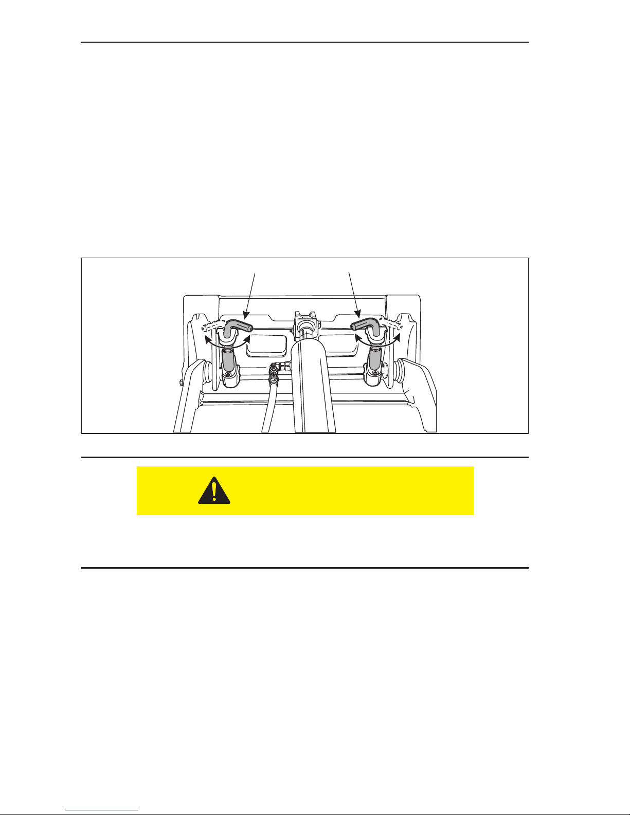
locks into the “locked” position (Item 1, Figure 3–25). As you rotate the lock pin, it will drop
downwards, securing the attachment to the machine. If the lock pin does not drop into the
locked position, start the engine and tilt the attachment slightly forwards or backwards until
the lock pins snap into place.
Figure 3-25 Attachment Locks in Locked Position
Until the attachment lock pins are fully in the locked position, the attachment has not
been safely secured to the machine. Do not stand near the attachment until it is fully
secured to the machine.
To release an attachment, rotate the attachment locks to the “unlocked” position (Item
1, Figure 3–26). The lock pins will automatically rise, releasing the attachment from the
machine. If the pins do not release the attachment or are very hard to rotate, start the engine
and tilt the attachment slightly forwards or backwards until the pins can be rotated.
11
Pins Locked
CAUTION
Page 45
Pre Start Inspection and Operation
3.19
Installation of Non-Hydraulically Powered Attachments
Make sure to keep your hands and feet away from the attachment during the unlocking
process. As the attachment becomes free from the machine, it may move.
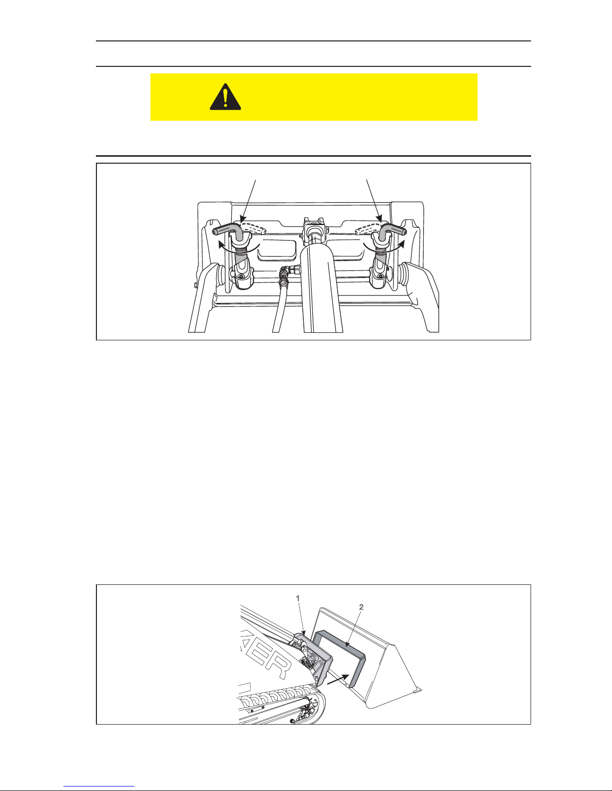
Figure 3-26 Attachment Locks in Unlocked Position
There are many available attachments that are very easy to install. To install any of the nonhydraulically powered attachments:
1. Position the attachment on a level surface.
NOTE: Clean the inside lower edge of the female attachment mounting plate (Item
2, Figure 3–27) to remove any debris that might interfere with the attachment
installation.
2. Start the machines engine, lower the loader arm and tilt the mounting plate
forwards
NOTE: Make sure that both of the attachment lock pins (Item 1, Figure 3–26) are
in the “unlocked” position. Refer to “Attachment Lock Pins” on page 3-18.
3. Slowly drive towards the attachment and align the top edge of the male mounting
plate (Item 1, Figure 3–27) and the upper lip of the female attachment mounting
plate (Item 2, Figure 3–27). Slide the upper edge of the male mounting plate into
the upper lip of the female attachment mounting plate.
Figure 3-27 Installing a Non-powered Attachment
1
1
Pins Unlocked
1
2
CAUTION
Page 46
Pre Start Inspection and Operation
3.20
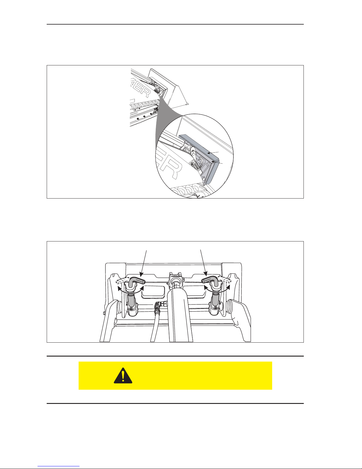
4. When the top of the attachment mounting plate (Item 1, Figure 3–28) is rmly
seated in the attachment mounting bracket (Item 2, Figure 3–28), tilt the
attachment mounting plate backward slightly to allow the lower edge of the
attachment mounting bracket to slide into place on the attachment mounting plate.
Figure 3-28 Attachment Installed
5. Shut the engine off.
6. Rotate the attachment lock pins (Item 1, Figure 3–29) into the locked position,
securing the attachment to the machine.
Figure 3-29 Attachment Locks in Locked Position
DO NOT go underneath the attachment when it is raised.
7. Start the engine and raise the attachment off the ground. Visually inspect the
bottom edge of the attachments mounting plate to make sure that both of the
attachment lock pins are securely holding the attachment in position.
1
2
11
Pins Locked
CAUTION
Page 47
Pre Start Inspection and Operation
3.21
1. Position the attachment on a level surface.
NOTE: Clean the lower edge of the female attachment mounting plate to remove
any debris that might interfere with the attachment installation.
2. Start the machine engine, lower the loader arm and tilt the mounting plate
forwards
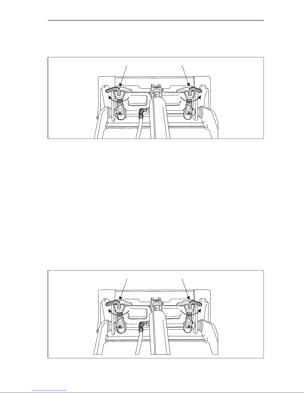
NOTE: Make sure that both of the attachment lock pins (Item 1, Figure 3–31) are
in the “unlocked” position.
Figure 3-31 Attachment Locks in Unlocked Position
Removal of Attachment
1. Lower the attachment onto a rm, level surface.
2. Shut off the machine engine.
3. Rotate the attachment lock pins to the UNLOCKED position (Item 1, Figure 3–30).
Figure 3-30 Attachment Locks in Unlocked Position
4. Start the engine and rotate the mounting plate downwards.
5. Back away from the attachment.
NOTE: It may be necessary to lower the loader arm assembly slightly to fully
disengage from the attachment.
Installation of Hydraulically Powered Attachments
There are many hydraulically powered attachments available that are very easy to install. To
install any of these attachments:
1
1
Pins Unlocked
1
1
Pins Unlocked
Page 48
Pre Start Inspection and Operation
3.22
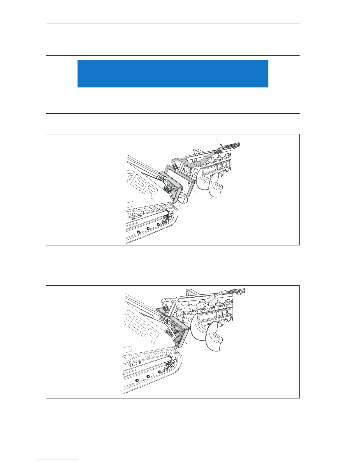
3. Slowly drive towards the attachment and align the top edge of the male mounting
plate (Item 1, Figure 3–32) and the upper lip of the female attachment mounting
plate (Item 2, Figure 3–32).
Make sure to position the attachments hydraulic hoses (Item 4, Figure 3–32) so that they are
not damaged during the installation process.
4. Tuck the upper edge of the male mounting plate into the upper lip of the female
attachment mounting plate.
Figure 3-32 Hydraulically Powered Attachment Installation
5. When the machines mounting plates top edge is seated in the attachment
mounting plate, tilt the machines mounting plate backwards slightly to allow the
lower edge of the machines mounting plate to slide into position. See Figure 3–33.
Figure 3-33 Hydraulically Powered Attachment Installed
NOTICE
3
2
1
4
1
Page 49
Pre Start Inspection and Operation
3.23
6. Shut the engine off.
DO NOT go underneath the attachment when it is raised.
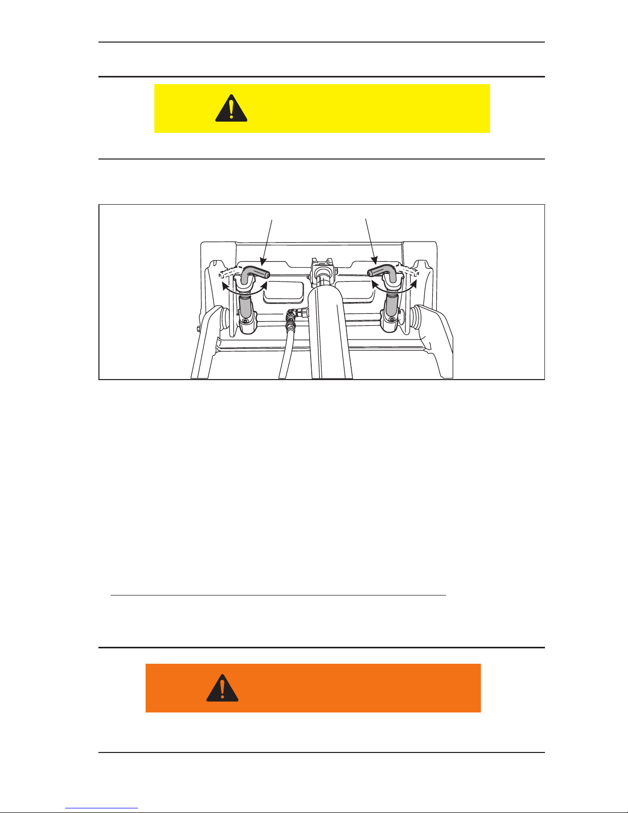
7. Rotate the attachment lock pins (Item 1, Figure 3–34) into the locked position
securing the attachment to the machine.
Figure 3-34 Attachment Locks in Locked Position
8. Start the engine and raise the attachment off the ground. Visually inspect the
bottom edge of the attachments mounting plate to make sure that both of the
attachment lock pins are securely holding the attachment in position.
9. Shut off the engine.
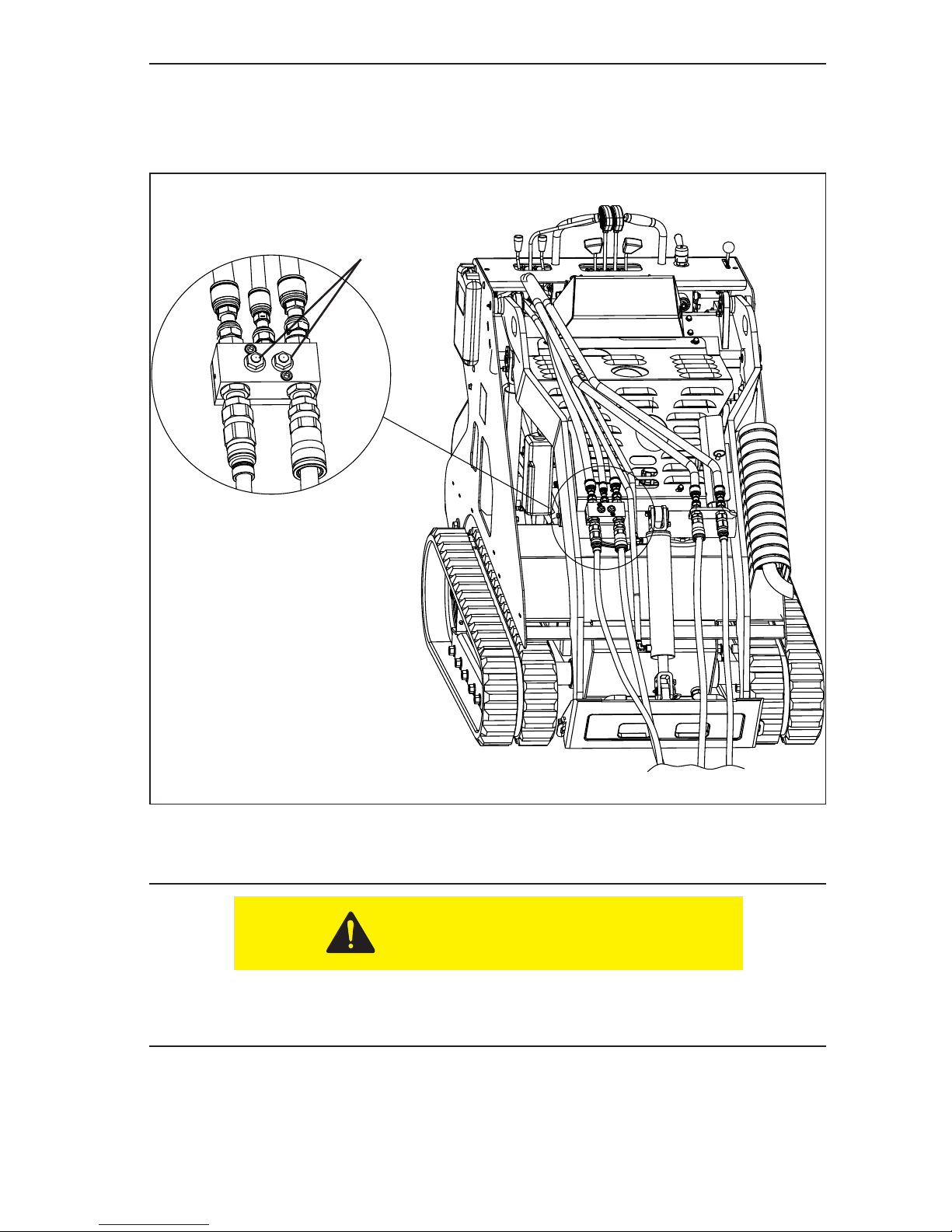
10. Relieve hydraulic pressure stored in the hoses. NOTE: To relieve pressure in
high ow side, depress push buttons located on the pressure relief block (see
Figure 3–37).
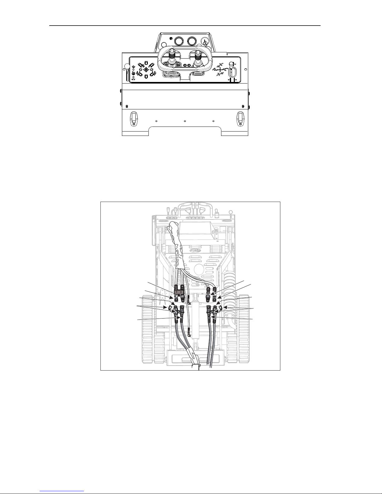
11. Attach the hydraulic hoses to the quick connects. See Figure 3–36.
NOTE: There are two hydraulic hoses that need to be connected. The quick
connect system prevents you from incorrectly connecting the hydraulic hoses, but
both hoses need to be connected for the attachment to operate.
Make sure that the engine has been shut off before beginning this procedure.
CAUTION
11
Pins Locked
WARNING
Page 50
Pre Start Inspection and Operation
3.24
a. Remove the protective covers (Items 4, Figure 3–36) from the attachment quick
connectors.
b. Wipe off the end of each of the connectors (Items 1, 2, 3, 5 Figure 3–36) to remove any
dirt or debris.
3-36 Auxiliary Hydraulic Quick Connects
c. Insert the attachment’s male coupling (Item 3, Figure 3–36) into the female bulkhead
quick coupling (Item 2, Figure 3–36) on the machine and push until the connector locks
into position.
d. Repeat the above process to connect the attachments’ female quick connect (Item 5,
Figure 3–36) on the other hose to the male bulkhead connector (Item 1, Figure 3–36) on
the machine.
e. Check the security of both connections by gently tugging on the attachment hoses to
make sure that the quick connects are seated properly.
4
2
1
4
3
5
1
2
3
5
Page 51
Pre Start Inspection and Operation
3.25
12. Make sure that the hydraulic hoses are routed so that they will not be in the way
or damaged during machine operation. Figure 3–37 shows how the hoses might
be routed to keep them out of the way during operation and prevent them from
being damaged.
Figure 3-37 Attachment Hydraulic Hose Routing (shown without hose covers)
13. The attachment is now ready to use.
Before starting the engine, make sure that the Auxiliary Hydraulic control lever is in the
NEUTRAL position. If this control is left in either the forward or reverse position and
the engine is started, the attachment will begin to function.
CAUTION
High Flow
Pressure Relief
Buttons
Page 52

Pre Start Inspection and Operation
3.26
Page 53
Pre Start Inspection and Operation
3.27
Removal of Hydraulically Powered Attachments
After use, the quick couplers and hydraulic uid will be very hot. Wear gloves when disconnecting the auxiliary hydraulic lines.
To remove a hydraulically powered attachment;
1. Lower the attachment to the ground and shut off the engine.
2. Relieve hydraulic pressure stored in the hoses. NOTE: To relieve pressure in
low ow side, move auxiliary control lever (see Item 2, Figure 3-39) back and
forth then leave in the detent. To relieve pressure in high ow side, depress push
buttons located on the pressure relief block (see Figure 3–37).
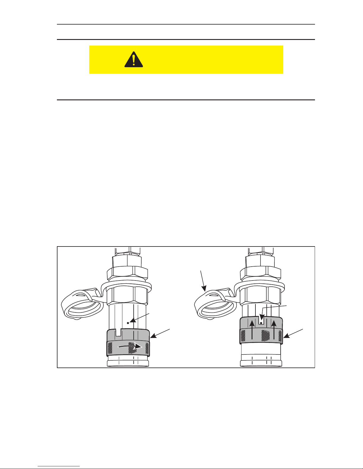
3. Some of the female couplings will have a lock button preventing accidental
disconnection. To release this type of quick connect, rotate the collar on the
female quick connect (Item 1, Figure 3–41) to align the notch on the collar with the
lock button (Item 2, Figure 3–41).
4. Slide the collar backwards on the female quick connect (Item 4, Figure 3–41) until
it stops against the lock button (Item 3, Figure 3–41). The male connector will be
released. Move the attachment hose away from the bulkhead tting.
5. If the female connector does not have the lock pin type collar, just slide the collar
backwards until the male connector is released.
Figure 3-41 Quick Connect Locking Collar
6. Repeat this procedure on the other hydraulic line.
7. Cover the hose connections with the dust caps (Item 5, Figure 3–41) and store the
hydraulic hoses to prevent damage. NOTE: If your hoses do not have dust caps,
keep hoses connected/coupled together to prevent dirt intrusion.
8. Follow the instructions in “Removal of Attachment” earlier in this section to
complete the attachment removal.
CAUTION
2
1
3
4
5
Page 54

Routine Service and Maintenance
4.1
Section 4 - Routine Service and Maintenance
The following information presents the routine service and maintenance required to make
sure that the machine functions safely and properly. More detailed service information is
contained in the Service Manual.
Table 4-1 Service Cycle Table
Activity
Daily
(10 Hours)
New
Machine
(20 Hours)
Weekly
(50 Hours)
Monthly
(200 Hours) Annual
Safety Placards I
Fuel C
Engine Oil C R* R† R†
Engine Oil Filter I R* R† R†
Engine Coolant I and A C**
Engine Radiator I****
Air Filter C R** R**
Fuel Filter I R**
Engine Idle Speed C
Check and Clean Battery Ter-
minals and Battery
I
Hydraulics
- Hydraulic Filter I R* R**
- Hydraulic Fluid Level I**** R**
- Hydraulic Hoses I
Grease I***
Track Tension I
Visual Check for
Loose/Missing Fasteners
I
Clean Oil Cooler Fins I
Inspect and Adjust
Track Tension
I
Inspect both Track Widening
Stop Bolts
I
Service Cycle - R = Replace I = Inspect A = Add C = Clean
† Refer to engine manual for oil change cycles.
* First 20 operational hours, then follow normal service cycle.
** Extremely dusty or dirty working conditions may require more frequent service/replacement.
*** Under very wet and muddy conditions, more frequent lubrication may be required.
****Check when cold, ll to max ll level.
Page 55
Routine Service and Maintenance
4.2
Daily Maintenance Procedures
Do the following procedures daily or every 10 operating hours:
1. Check condition of all warning and instructional decals. Before operating the
machine, replace any missing or damaged decals.
NOTE: Make sure to read and understand all WARNING and SAFETY decals
before operating the machine.
• Allow engine to cool before lling fuel tanks.
• Do not overll because fuel could spill onto hot engine parts and ignite or
explode.
• Make sure engine is turned off.
2. Check engine fuel and ll as needed:
a. The Boxer has a saddle tank (Item 1, Figure 4–1), on each side of the machine.
Figure 4-1 Fuel Level Check
b. Remove cap (Item 2, Figure 4-1) and visually inspect fuel level. Make sure that each
tank has been lled on a daily basis.
c. Carefully pour fuel into the tank, not exceeding level at bottom of ll spout.
CAUTION
Page 56
Routine Service and Maintenance
4.3
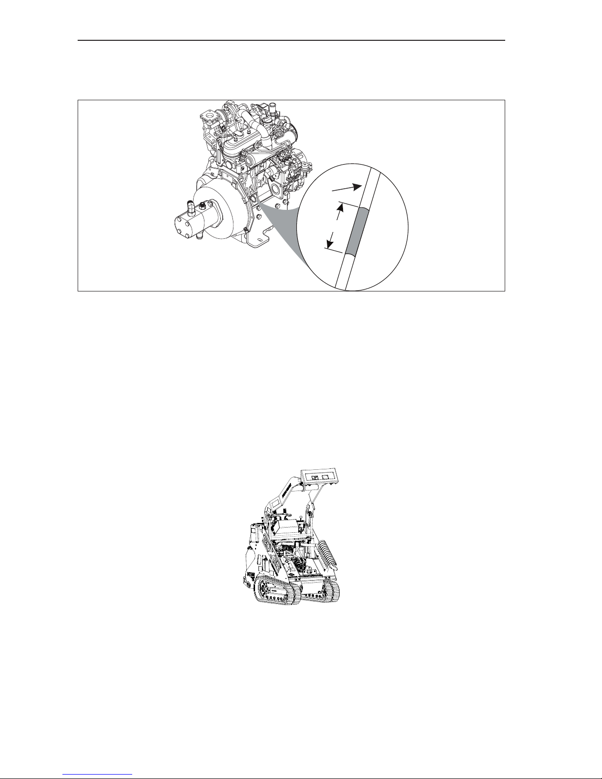
3. Check engine oil -
a. Make sure that the engine is OFF.
b. Pull out the dipstick (Item 1, Figure 4–2) and look for the “FULL” line.
Figure 4-2 Oil Level Check
c. If the engine oil level is below the add line, indicated by the letter “A” on the dipstick,
carefully add the proper amount of oil through the engine oil ller (Item 1, Figure
4–3). The correct SAE viscosity grade of oil is determined by the minimum ambient
temperature during cold engine start-up, and the maximum ambient temperature during
operation. The engine is lled at the factory with Chevron Delo 400 Multigrade SAE
15W-40. The recommended ambient temperature range for this oil is 14° F (-10° C)
minimum to 122° F (50° C) maximum. Refer to the engine Operation and Maintenance
Manual for additional information on the proper selection of engine oil.
NOTE: Make sure to reinstall and secure the oil ller cap.
Figure 4-3 Engine Oil Fill
NOTE: Extremely dusty or dirty working conditions may require more frequent
checking, lling and/or changing of engine oil.
d. After lling the oil, wait a few minutes and check the oil level again.
e. Make sure to securely reinstall the dipstick into the dipstick tube before starting the
engine.
OK
x
x
x
x
x
F
A
1
Page 57
Routine Service and Maintenance
4.4
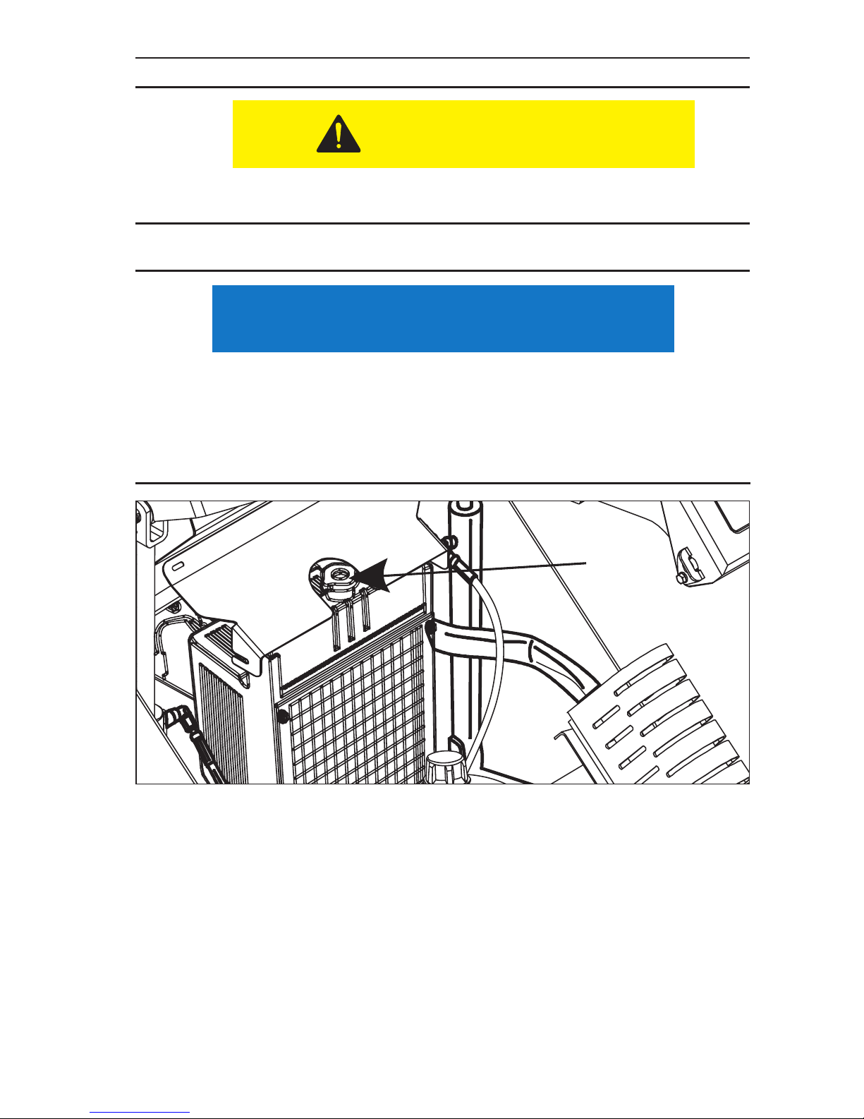
4. Check engine coolant level.
•
The coolant is hot and under pressure. DO NOT check until the engine radiator is
cool to the touch.
• Remove radiator cap (Item 1, Figure 4–4) and check the radiator uid level. The proper
coolant level will be to the bottom of ller neck.
• The overow bottle is a non-pressurized container that is only for any high heat
overow. Do not add coolant to this container. It will not be drawn into the engine.
• If coolant is required, make sure to add the proper coolant as shown in the Engine
Manual.
CAUTION
NOTICE
Figure 4-4 Filler Cap
1
Page 58
Routine Service and Maintenance
4.5
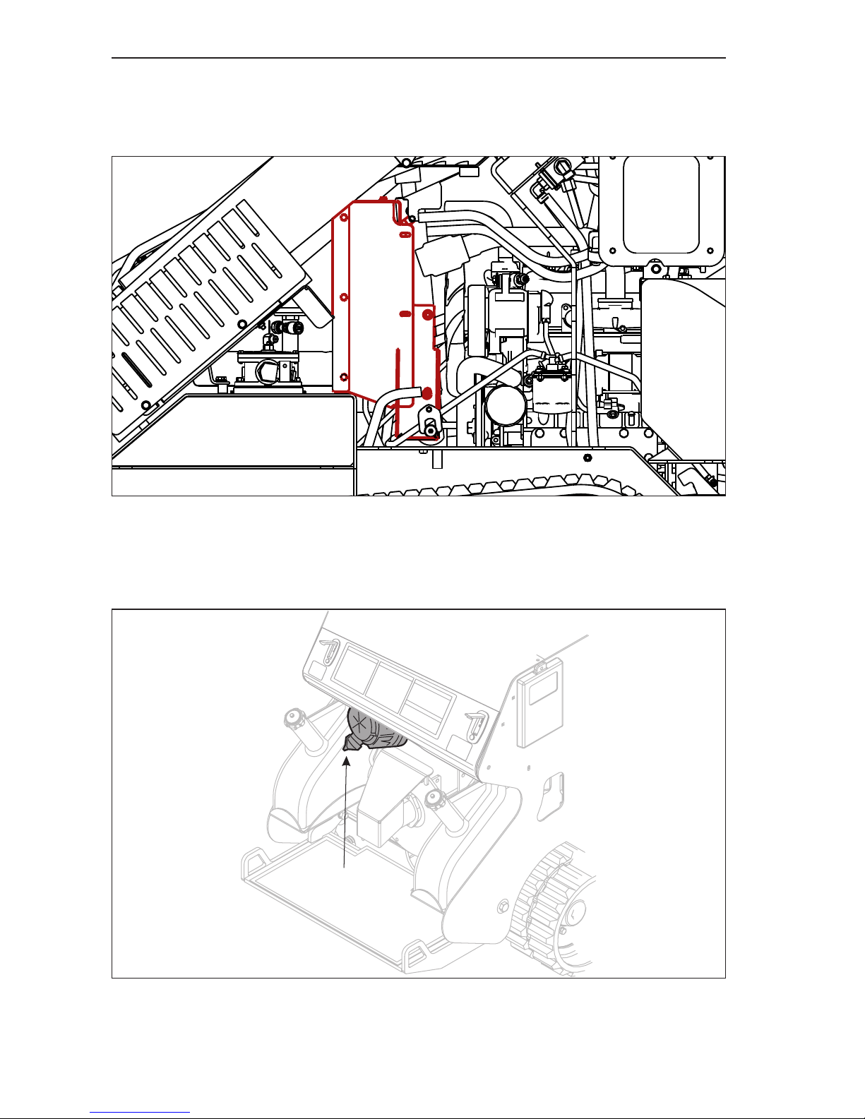
5. Inspect the radiator to make sure that the air ow is not blocked. The fan located
on engine side of radiator unit is a suction fan, which draws air from inside the
machine. Check the engine side of the radiator (Figure 4–5) to make sure that
debris has not been sucked against the radiator blocking air ow.
NOTE: Some items in Figure 4–5 have been removed for clarity.
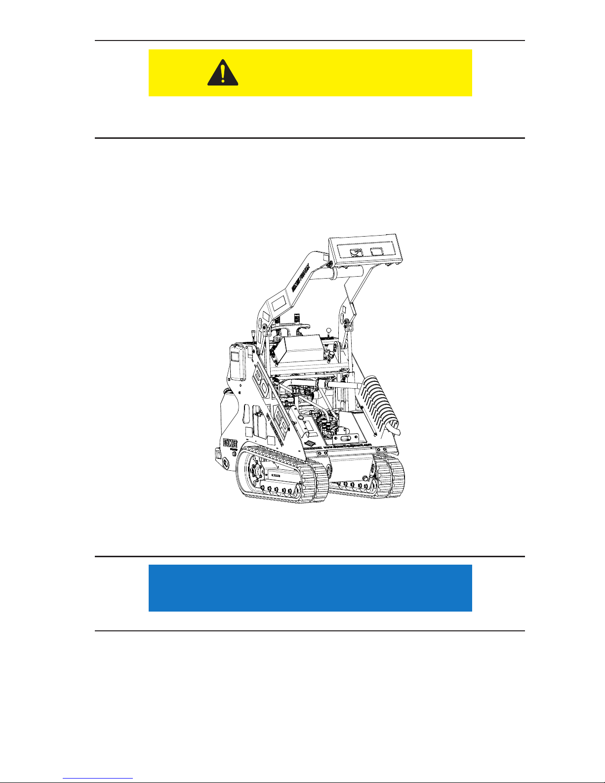
6. Release dirt from separator tube at the bottom of the air lter by squeezing the
rubber dust ejector valve (Item 1, Figure 4–6) underneath the air lter.
Figure 4-6 Air Filter Dirt Release
Figure 4-5 Radiator Air Flow Inspection
1
Page 59
Routine Service and Maintenance
4.6
If you are checking the uid level after a period of use, the hydraulic system and
hydraulic uid will be very hot. Wear gloves when inspecting the hydraulic uid level.
7. Check hydraulic oil level, ll as needed with the proper hydraulic oil - be sure
engine is off.
a. The hydraulic oil dipstick can be reached through the opening in the front cover.
b. Unscrew the dipstick assembly and remove from the machine. (Item 1, Figure 4–7).
c. Make sure that the hydraulic uid is between the marker holes in the dip stick.
Figure 4-7 Hydraulic Fluid Level Dip Stick
d. Add the proper hydraulic uid (Chevron Rykon Premium ISO 46 hydraulic uid or
equivalent) until the uid level is 1/4” below marker hole in the dipstick.
• Do not over ll the hydraulic system. Damage to the hydraulic system might result.
CAUTION
NOTICE
Page 60

Routine Service and Maintenance
4.7
8. Check hydraulic hoses.
Hydraulic oil under pressure can penetrate body tissue causing serious
injury and possible death. When troubleshooting a hydraulic system
for leaks, always use cardboard or wood as a detector. DO NOT USE
YOUR BARE HANDS. If you are injected with hydraulic oil or any other
uids, immediately seek treatment by a doctor trained in the treatment of
penetrating uid injuries.
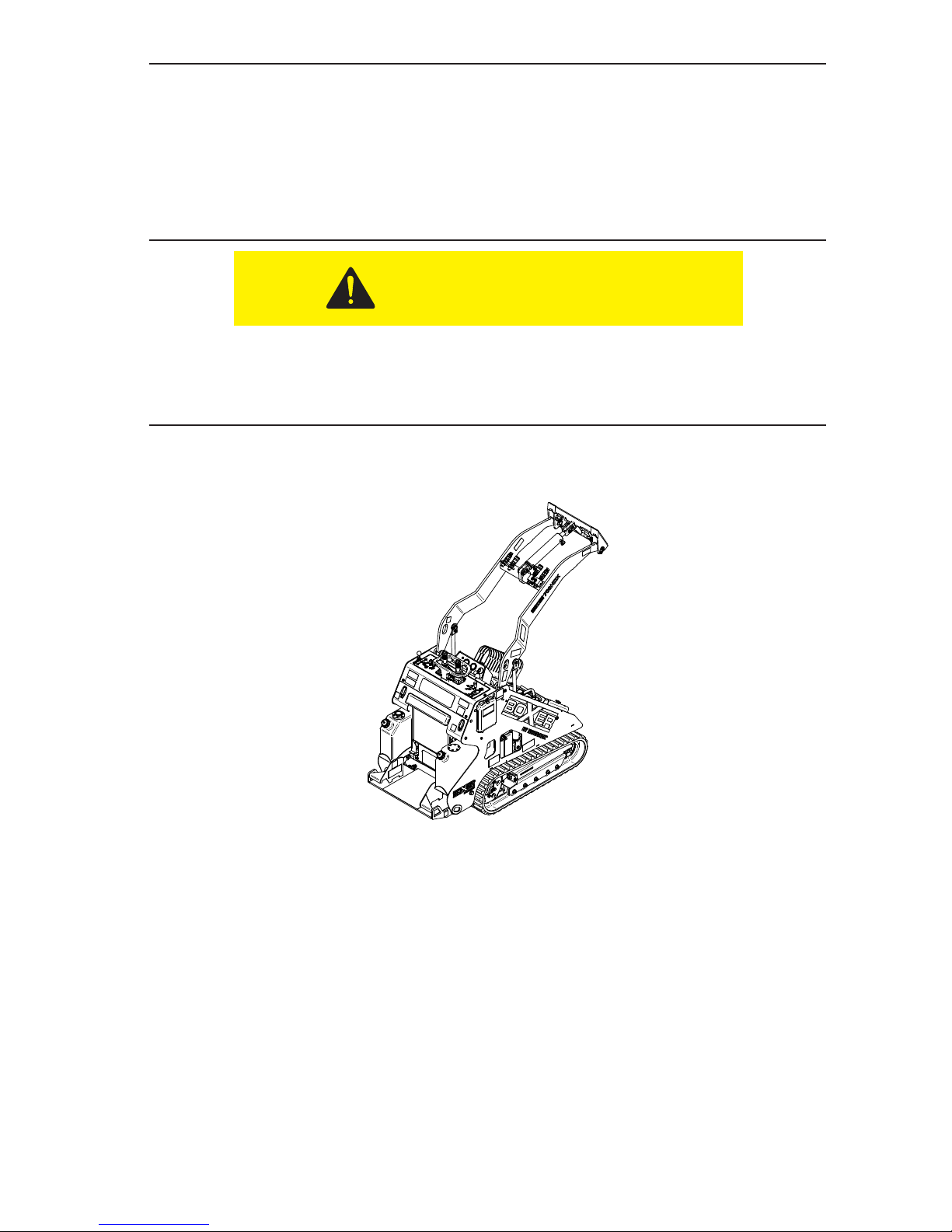
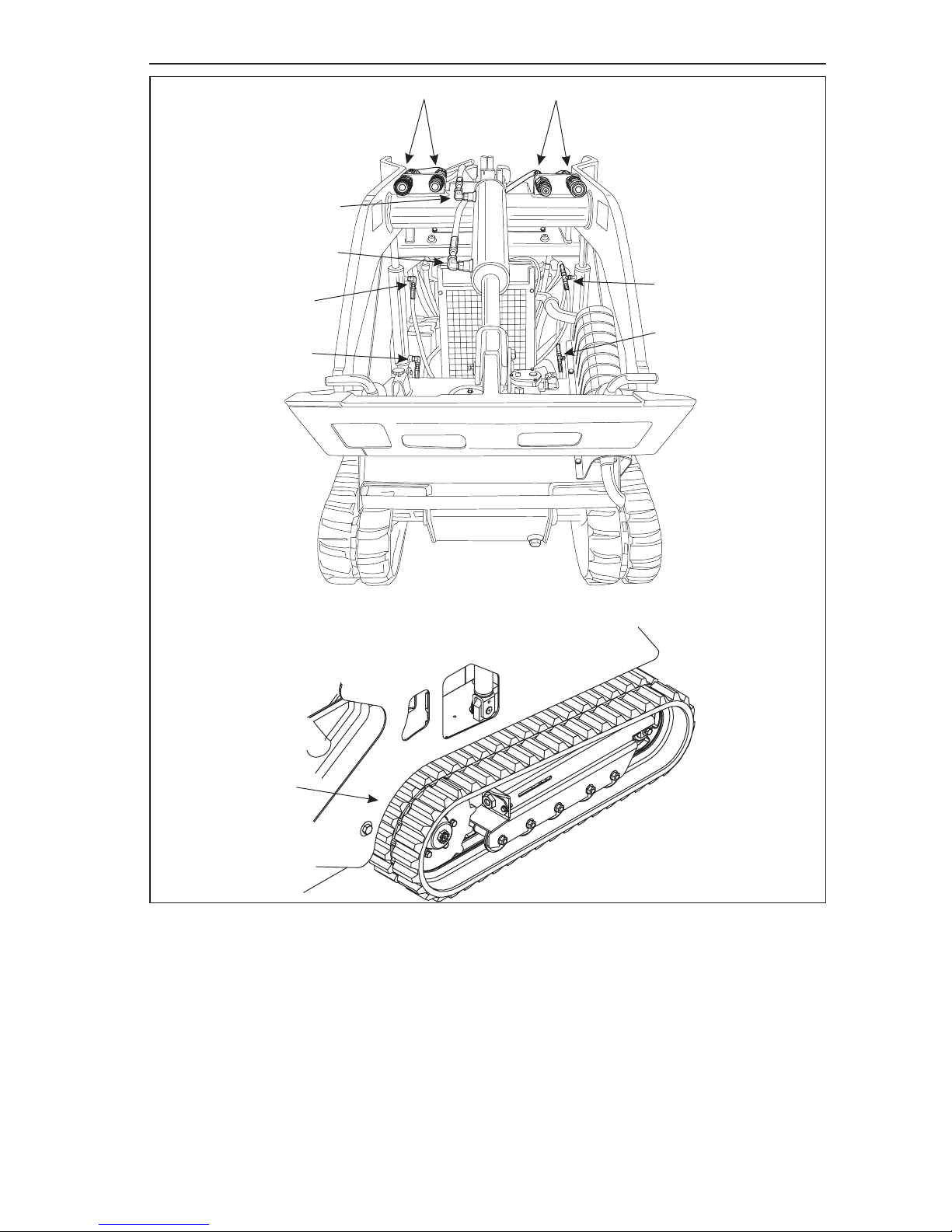
a. Fully raise the loader arm, install and secure the safety support.
b. Follow all of the hoses, line and tubes from the control valve to their end (Items 2, 3, 4
and 5, Figure 4–8). Inspect the connections and look for signs of leaking hydraulic uid,
wear or damage.
c. Carefully inspect both sets of quick couplers (Item 1, Figure 4–8) to make sure that they
are not damaged or leaking. Make sure to check for signs of leakage or damage to the
drive motors and to their hydraulic connections.
NOTE: Item 3 is the track extension cylinder located underneath the machine, but
protected by the belly pan. If any leakage from underneath the machine is noticed,
do not use the machine and have it inspected and repaired by your servicing
dealer.
WARNING
Page 61
Routine Service and Maintenance
4.8
Figure 4-8 Inspect Hydraulic Lines and Fittings
d. If any signs of damage are visible, do not operate the machine until repairs have
been made.
1
1
2
2
3
4
4
5
5
Page 62
Routine Service and Maintenance
4.9
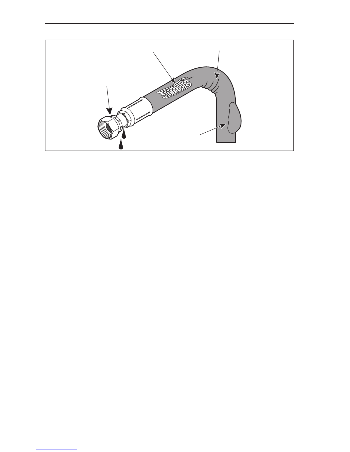
e. Some examples of common hydraulic hose damage are shown in Figure 4–9:
Figure 4-9 Hydraulic Hose Damage
9. Lubricate pivot shafts with grease. There are 14 lubrication points on this machine,
see Figure 4–10.
Figure 4-10 Lubrication Points
NOTE: Extremely dusty or dirty working conditions may require more frequent
service/replacement.
1. End ttings damaged or leaking.
2. Outer covering chafed or cut, and wire reinforcing is exposed.
3. Hose shows signs of kinking or crushing.
4. Outer covering ballooning
1
3
4
2
Page 63
Routine Service and Maintenance
4.10
10. Check both track assemblies for:
a. The proper tension. Too little or too much tension can cause premature track wear and
travel motor damage.
b. Make sure that the tracks are not worn or damaged.
c. Make sure that the nylon guide block is centered within the track and is guiding the
track properly.
d. Make sure the Track Adjustment Guide Bushings (located in Frame) are not worn or
damaged.
e. Check for loose or missing fasteners.
f. Inspect for any loose or missing bolts or fasteners.
g. Tighten or replace any missing bolts or fasteners before operating the machine.
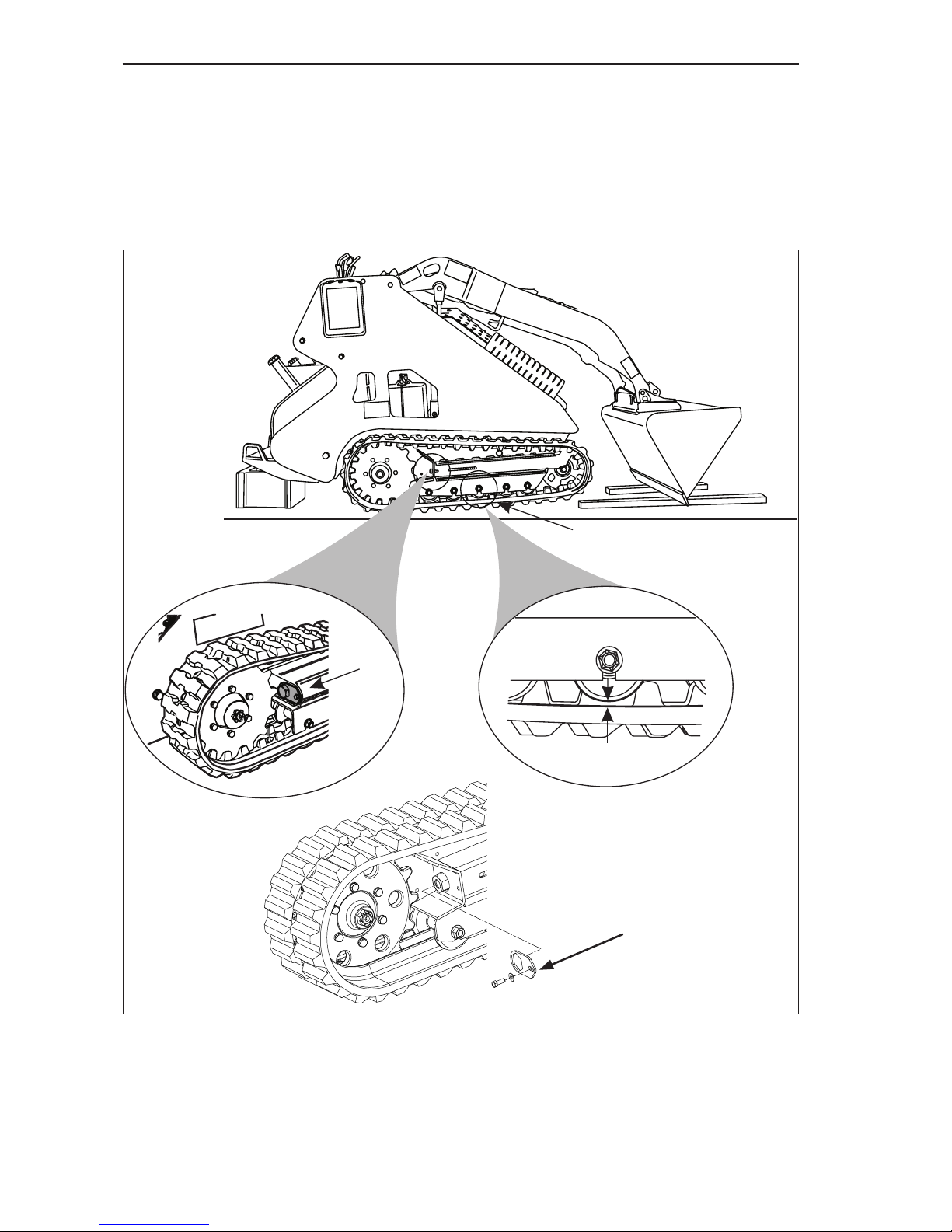
11. Check for proper track tension.
a. Raise the machine off the ground and support it using a device capable of safely
supporting 4000 lbs. (1820 kg) See Figure 4–11 for suggested location of the support
devices.
b. Tilt the bucket downwards until the cutting edge is touching the ground. See Figure
4–11.
c. Lower the loader arm assembly, pushing the front of the machine upwards. Continue
raising the machine until the rear drive sprocket is off the ground. Shut off the engine.
Keeps hands and ngers from under the track and track guide rollers.
d. Measure the gap between the bottom of the center bogey guide roller (Item 1, Figure
4–11) and the track. The proper tension will be about a 1/4” - 3/8” (6 mm - 10 mm)
deection.
e. If an adjustment is needed, remove tension lock plate (see Item 3, Figure 4-9) then rotate
the track tension adjustment nut (Item 2, Figure 4–11) until the proper track deection
measurement is achieved.
f. With the tracks still off the ground, start the engine and rotate just the track being
adjusted three or four times in both forward and reverse. Shut off the engine after
rotating the track.
g. Remeasure the deection dimension. If good, install tension lock plate and bolt.
h. Check the other track for the correct tension measurement. If needed, repeat Steps 10e -
10g.
i. Lower the machine onto the ground and remove the support devices.
12. Inspect the Track Widening Stop Bolts for:
a. Signs of damage or wear:
- Fully retract the tracks and make sure that the stop bolts (Item 1, Figure 4–12) are not
bent or damaged.
- If the bolt shows any signs of damage, replace the bolt.
- Extend the tracks to make sure that the track assemblies move freely.
CAUTION
Page 64
Routine Service and Maintenance
4.11
Figure 4-11 Track Deection Measurement and Adjustment
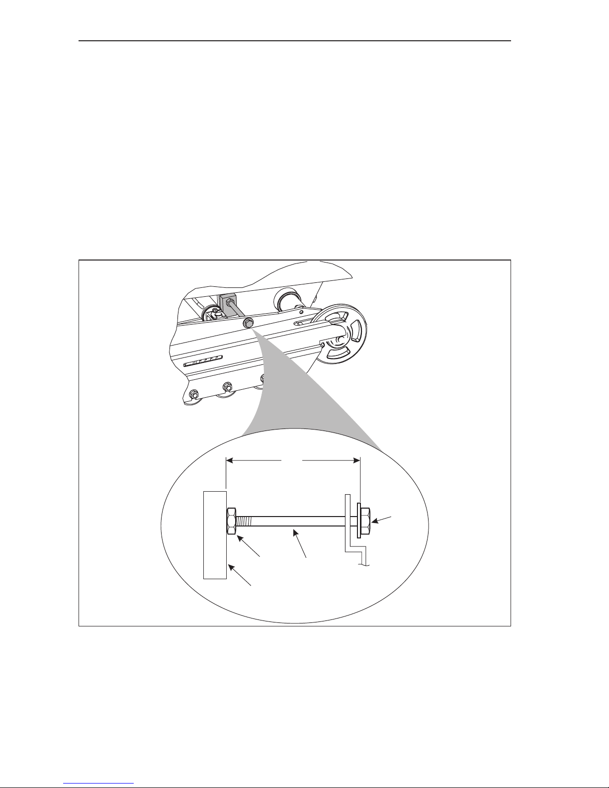
NOTE: The distance between the inner edge of the mounting block and inner
edge of the stop bolt head must be 6 3/4” (17 cm). If this measurement is not
maintained, damage to the machine may occur.
b. Make sure that the stop bolt lock nuts (Item 2, Figure 4–12) are tight against the
mounting block (Item 3, Figure 4–12).
c. Make sure to check both track assembly stop bolts.
1
2
1/4”-3/8”
3
Page 65

Routine Service and Maintenance
4.12
Figure 4-12 Track Extension (Widening) Stop Bolt
1
2
3
Page 66
Routine Service and Maintenance
4.13
13. If the stop bolt lock nut (Item 3, Figure 4–13) is loose, check the distance between
the mounting block (Item 4, Figure 4–13) and bottom side of the bolt head (Item 1,
Figure 4–13). The correct measurement is 6 3/4” (17 cm) from the outside edge of
the stop block to the bottom edge of the head of the stop bolt (Item 1, Figure 4–13).
14. If an adjustment to the track widening stop bolt is required,
a. Loosen the lock nut (Item 3, Figure 4–13),
b. Rotate the stop bolt (Item 2, Figure 4–13) to set the correct measurement of 6 3/4” (17
cm) from the outside edge of the stop block to the bottom edge of the head of the stop
bolt (Item 1, Figure 4–13).
c. After adjusting the stop bolt, make sure to fully tighten the lock nut, securing the stop
bolt.
NOTE: The distance between the inner edge of the mounting block and inner
edge of the stop bolt head must be 6 3/4” (17 cm). If this measurement is not
maintained, damage to the machine may occur.
Figure 4-13 Track Widening Stop Bolt Adjustment
1
2
3
6 3/4”
4
Page 67
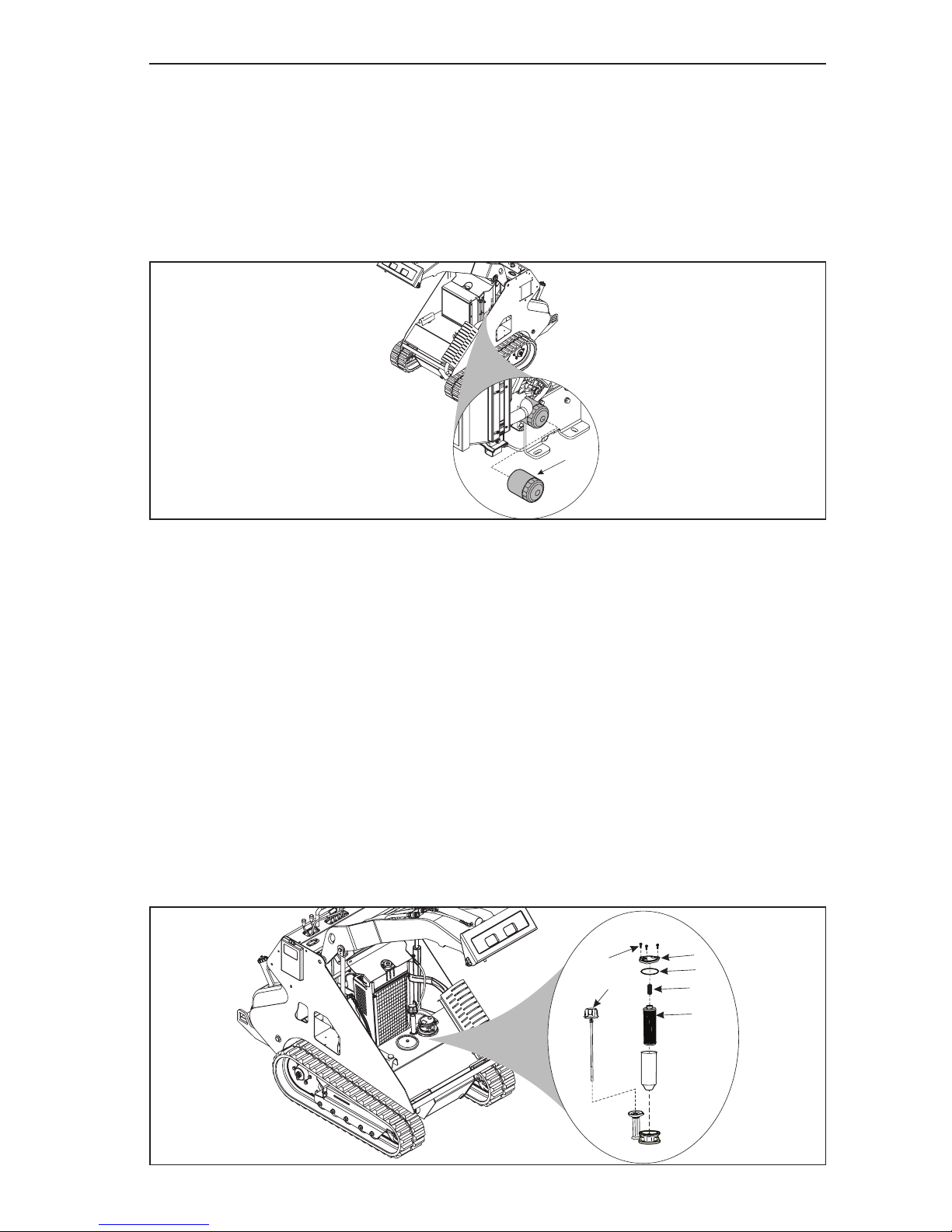
Routine Service and Maintenance
4.14
New Machine Brake-in Maintenance Procedures
Do the following after the rst 20 operating hours for a new machine only.
1. Change engine oil. Refer to the engine manual for the proper engine oil changing
instructions.
2. Change engine oil lter, which is located on the left side of the - engine. Refer to
the engine manual for the proper engine oil lter changing instructions. The oil
lter is located at the front of the engine (Item 1, Figure 4–14).
Figure 4-14 Engine Oil Filter
3. Replace the hydraulic lter. See Service Manual and Figure 4–15.
a. Remove the three bolts (Item 1, Figure 4–15) holding the lter cover (Item 2, Figure
4–15) in place.
NOTE: Press downwards on lter cover to relieve the upwards pressure from the
spring.
b. Remove the lter cover and spring (Item 4, Figure 4–15).
c. Remove the lter element (Item 5, Figure 4–15) and replace with a new lter element.
d. Inspect the lter cover O-ring (Item 3, Figure 4–15) for any signs of wear or damage.
Replace as needed.
e. Reinstall spring and lter cover.
NOTE: Make sure that the O-ring is properly seated in the lter cover.
f. Start and run the engine for about 30 seconds.
Using the hydraulic oil level dip stick (Item 6, Figure 4–15), check the hydraulic oil level.
Add the appropriate hydraulic uid as needed.
Figure 4-15 Hydraulic Oil Filter Assembly
1
1
2
3
4
5
6
Page 68
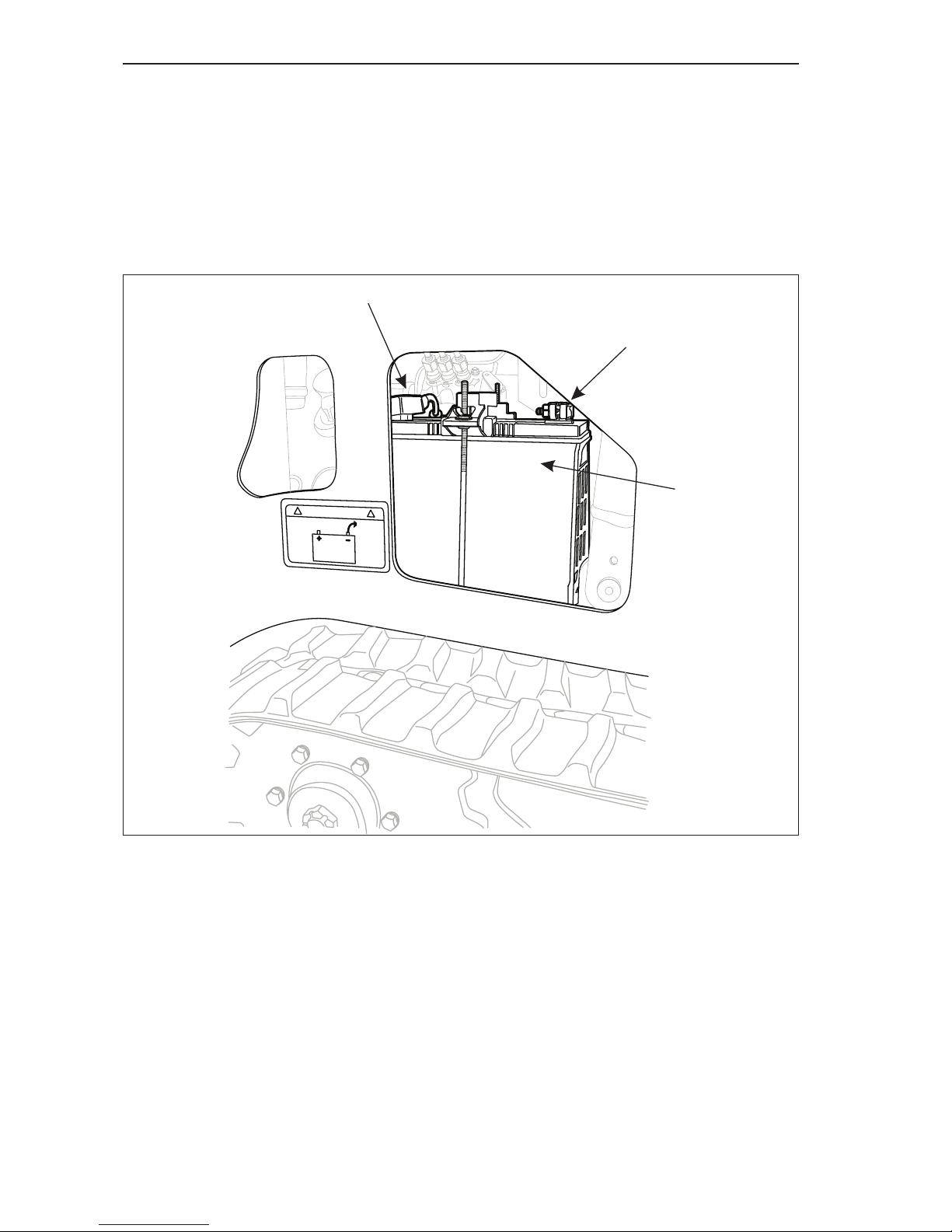
Routine Service and Maintenance
4.15
Weekly Maintenance Procedures
Do the following procedures weekly or every 50 operating hours:
1. Do all Daily maintenance procedures
2. Check the battery (Item 1, Figure 4–16) and cable connections (Items 2 and 3,
Figure 4–16) for signs of leaking, corrosion or damage. (Some items have been
removed for clarity.)
NOTE: The electrical system on this machine is a NEGATIVE ground system.
Figure 4-16 Battery and Cable Connections
1
3
2
Page 69
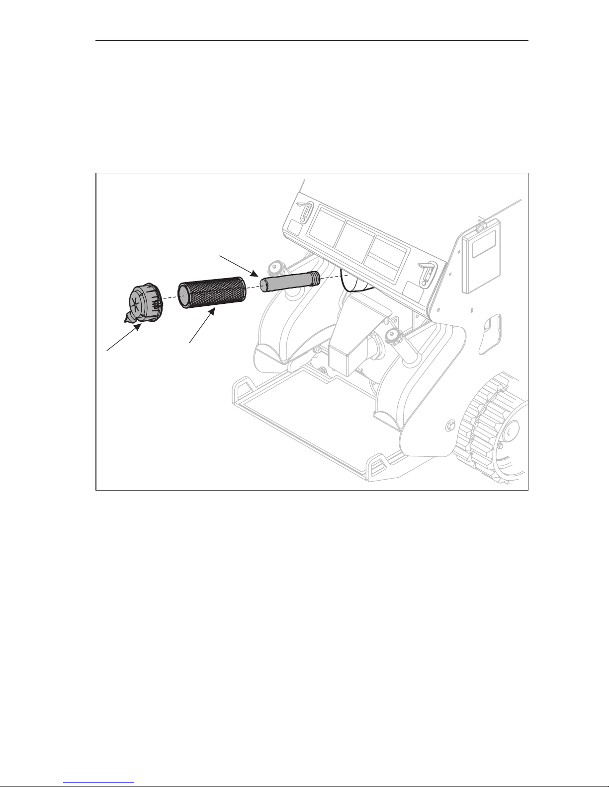
Routine Service and Maintenance
4.16
Monthly Maintenance Procedures
Do the following procedures monthly or every 200 operating hours:
1. Do all Daily and Weekly maintenance procedures
2. Replace engine oil and engine oil lter - see engine manual
3. Check air lter and replace outer paper element (Item 2, Figure 4–17).
4. Replace the outer paper element (Item 2, Figure 4–17) and check inner element
(Item 3, Figure 4–17)
Figure 4-17 Check Engine Air Filter
a. Unhook the two retaining clips and remove the end cap from the air cleaner housing.
b. Pull the outer air cleaner element out of the housing.
c. After the main element is removed, check the condition of the inner element . It should
be replaced whenever it appears dirty, typically every other time the main element is
replaced. Clean the area around the base of the inner element before removing it, so dirt
does not get into the engine.
d. Do not wash the paper element and inner element or use pressurized air, this will
damage the elements. Replace dirty, bent or damaged elements with new genuine
Morbark repair parts as required.
e. Handle new elements carefully; do not use if the sealing surfaces are bent or damaged.
f. Check all parts for wear, cracks, or damage.
g. Replace any damaged components.
h. If needed, install the new inner element, followed by the outer element. Slide each fully
into place in the air cleaner housing.
1
2
3
Page 70
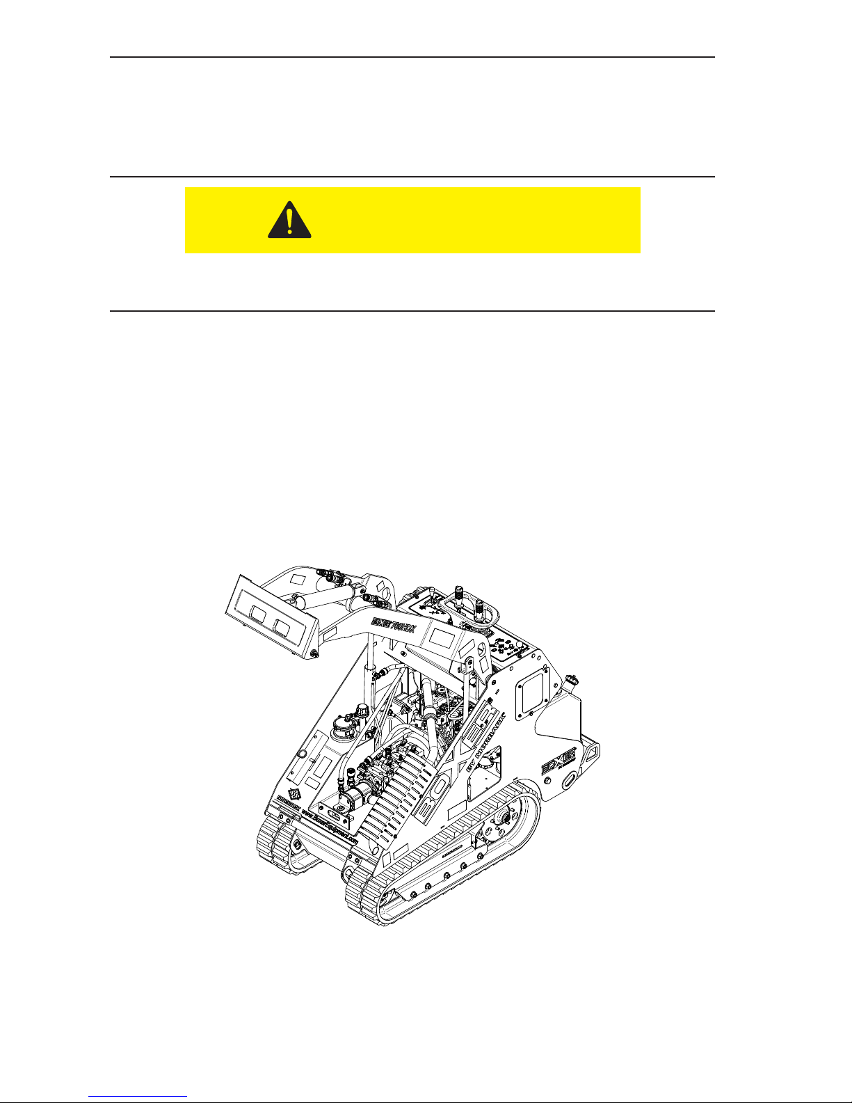
Routine Service and Maintenance
4.17
i. Reinstall the end cap so the dust ejector valve is down and secure the end cap with the
two retaining clips.
*In extremely dusty or dirty operating conditions, this service cycle may need to be
shortened.
5. Replace fuel lter.
Make sure to clean up any spilled fuel from in and around the engine compartment of
the machine. Spilled fuel may be ignited by a hot engine.
a. Locate fuel lter assembly through the opening in the frame along the left side of the
machine.
b. Unscrew the lter canister.
NOTE:
• The fuel lter will be lled with diesel fuel. Make sure to drain the fuel from the lter
into an appropriate container.
• Dispose of the used fuel lter in an appropriate manner, and according to State and
Local regulations.
c. Before installing the new canister lter, lubricate the rubber sealing ring on top of the
lter with a small amount of diesel fuel.
d. Install the new lter.
Figure 4-18 Fuel Filter Assembly
NOTE: Place a container underneath the fuel injection pump to catch any spilled
diesel fuel. Dispose of the used fuel in an appropriate manner.
CAUTION
Page 71
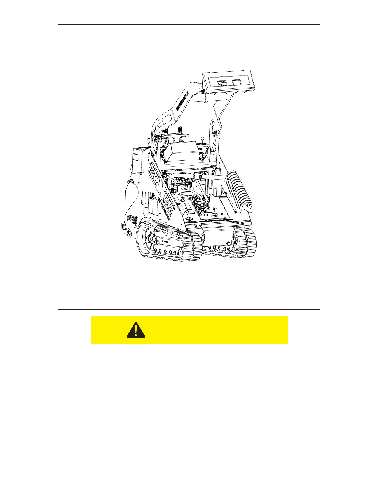
Routine Service and Maintenance
4.18
e. Loosen, but DO NOT remove, the air bleed bolt (Item 2, Figure 4–19).
f. Raise and lower the primer pump handle (Item 1, Figure 4–19) until only diesel fuel
without any air bubbles comes out of the air bleed.
g. Fully tighten the air bleed bolt.
Figure 4-19 Fuel Feed Pump Lever
6. Check battery for signs of leakage and for corrosion on the battery cables.
• On a monthly basis, check the battery for signs of leaking electrolyte. If any signs of
damage are visible, remove and replace the battery.
Wear the proper protective clothing when handling the battery. Leaking battery uid
contains acid that can cause burns. Fumes from the leaking uid can cause respiratory
problems.
• To prevent corrosion, spray on a battery protectent and sealer onto both terminals and
cable clamps after cables are installed.
• The electrical system on this machine is a NEGATIVE ground system.
• Check both of the battery cables for signs of damage or corrosion. Loosen the cable
clamps and remove the cable from the battery. Clean the terminals with a battery brush.
Reinstall and secure the cable clamps.
CAUTION
Page 72
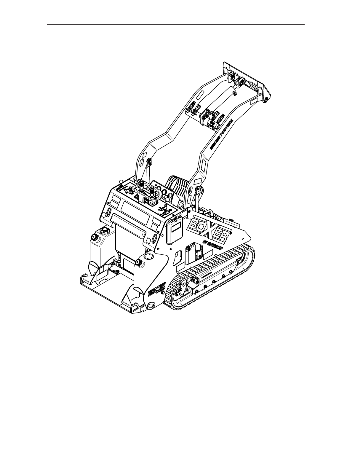
Routine Service and Maintenance
4.19
• Check the battery hold down clamp (Items 4 and 6, Figure 4–20) to make sure that the
battery is being held securely to the machine.
NOTE: If the battery needs to be replaced, make sure to dispose of the old battery
according to local regulations.
Figure 4-20 Battery and Connections
Page 73
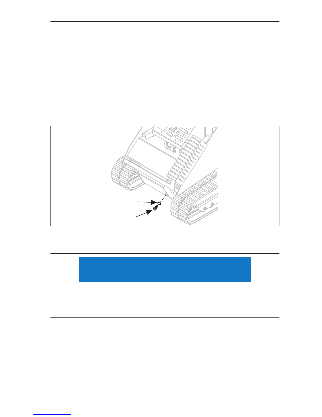
Routine Service and Maintenance
4.20
Annual Maintenance Procedures
Do the following procedures annually:
1. Do all Daily, Weekly and Monthly maintenance procedures.
2. Replace air lter** See page 4-14, Step 3.
3. Check engine idle speed (Refer to engine manual).
4. Replace hydraulic uid**.
a. Place a suitable sized container at the left front corner of the Boxer.
b. Remove the hydraulic tank drain plug (Item 1, Figure 4–21) and drain all hydraulic uid
from the machine.
NOTE: Make sure to inspect the O-ring (Item 2, Figure 4–21) on the drain plug.
Replace the O-ring if any signs of damage are noted.
Figure 4-21 Hydraulic Tank Drain Plug
c. When all of the hydraulic uid has drained out of the tank, reinstall and secure the drain
plug.
• Make sure to dispose of the used hydraulic uid in an appropriate manner and according
to State and Local regulations.
• The hydraulic lter will be lled with hydraulic uid. Make sure to dispose of the used
hydraulic lter in an appropriate manner and according to State and Local regulations.
d. Replace hydraulic lter. See page 4-14, Step 3.
NOTE: The hydraulic oil dipstick can be reached through the opening in the front
cover.
1
2
NOTICE
Page 74
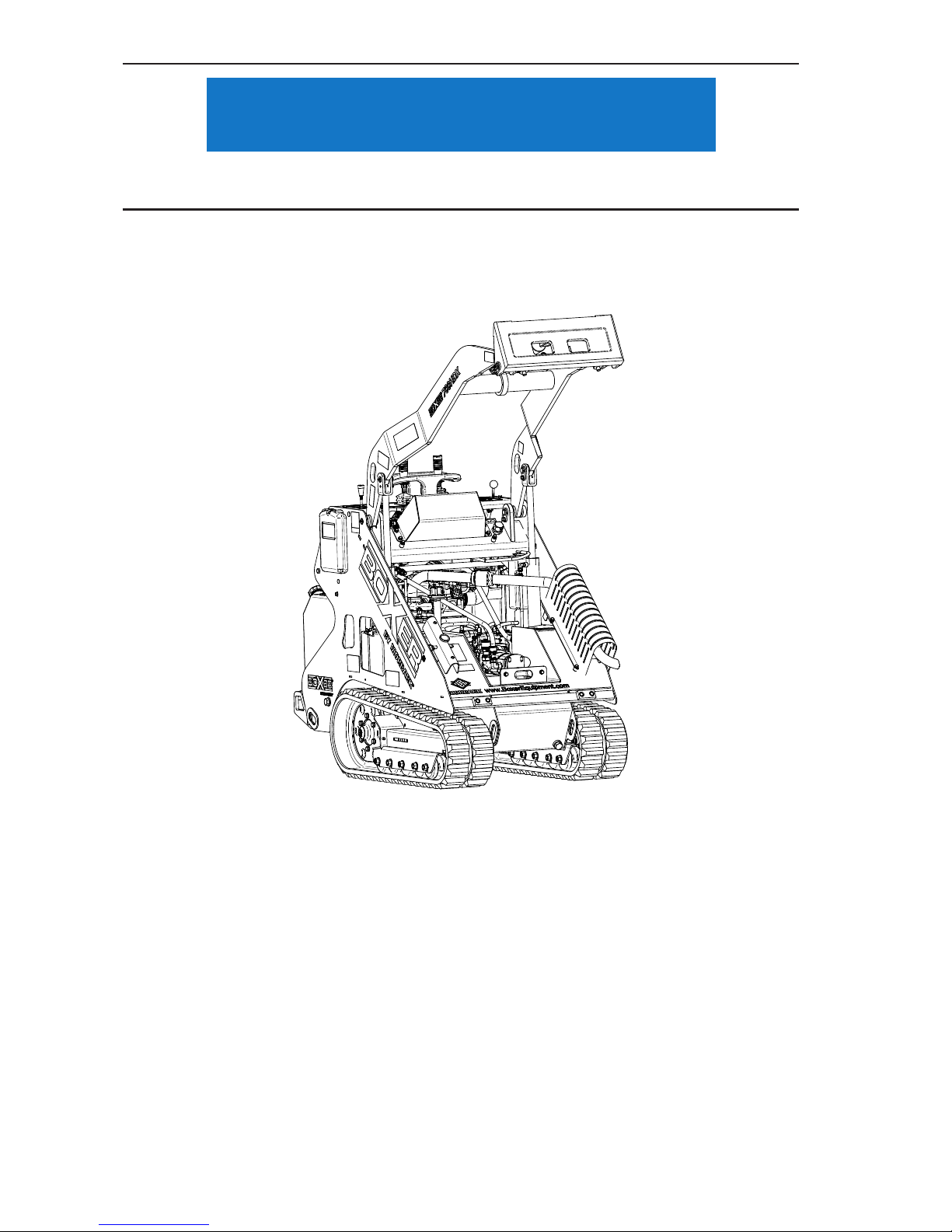
Routine Service and Maintenance
4.21
Do not over ll the hydraulic system. Damage to the hydraulic system might result.
e. Unscrew the dipstick assembly and remove from the machine and ll the hydraulic tank
with the proper hydraulic uid (Chevron Rykon Premium ISO 46 or equivalent) until
the uid level is at but not above the upper marker hole in the dipstick.
Figure 4-22 Hydraulic Fluid Level Dip Stick
f. Start the machine and run the engine at low idle for several minutes. Shut off the engine.
g. Recheck the hydraulic uid level as described above.
NOTICE
Page 75
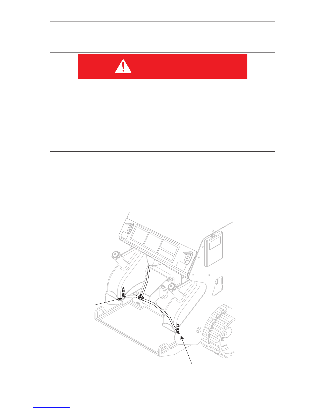
Routine Service and Maintenance
4.22
General Maintenance
Draining Fuel Tank (Diesel)
1. DIESEL FUEL IS EXTREMELY FLAMMABLE AND HIGHLY EXPLOSIVE.
2. A FIRE OR EXPLOSION FROM DIESEL FUEL CAN BURN YOU OR OTHERS
AND CAUSE PROPERTY DAMAGE.
3. DRAIN FUEL FROM TANKS WHEN THE ENGINE IS COLD.
4. FUEL TANKS SHOULD ONLY BE DRAINED IN AN AREA THAT IS WELL
VENTILATED.
5. WIPE UP ANY DIESEL FUEL THAT SPILLS.
1. Park the machine on a level surface, to ensure that the fuel tank is completely
drained.
2. Lower the loader arms and stop the engine and remove the key.
3. Allow the engine to cool completely.
4. Shut off the fuel valve (Item 1, Figure 4–23) located on the bottom of each of the
fuel tanks.
Figure 4-23 Fuel Shut Off Valves
DANGER
1
1
Page 76
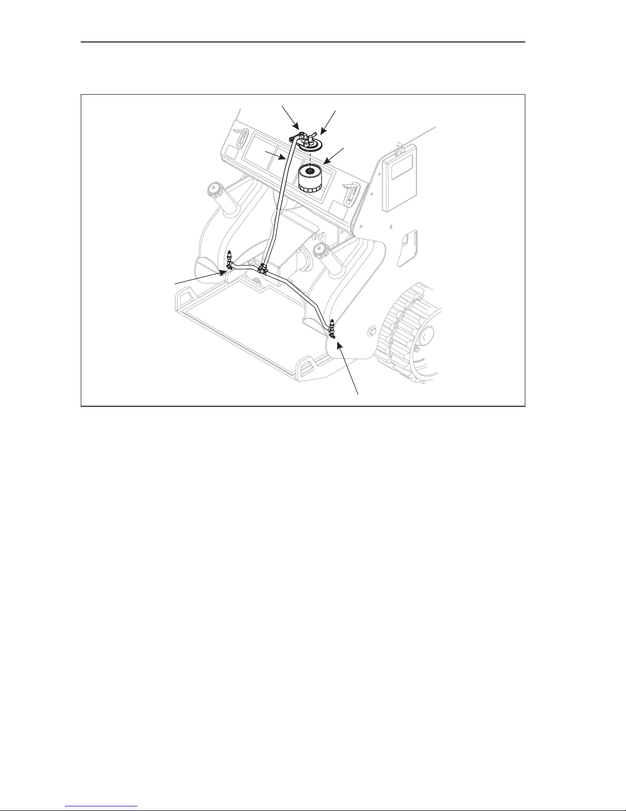
Routine Service and Maintenance
4.23
5. Loosen the intake hose clamp (Item 2, Figure 4–22) at the top of the fuel lter
assembly (Item 1, Figure 4–22). Slide the clamp along the fuel line (Item 3, Figure
4–22) away from the fuel lter assembly.
Figure 4-24 Fuel Filter
6. Pull the fuel line off the fuel lter assembly and place the line in a suitable sized
container.
NOTE:
a. Each of the fuel tanks holds approximately 4.5 gallons of fuel.
b. Make sure that the fuel hose is positioned lower than the fuel valves to make sure that
all fuel is drained from the tanks.
7. Open the fuel valves on the bottom of each tank and allow the fuel to drain into the
drain pan.
8. Install a new spin on fuel lter (Item 4, Figure 4–24) as described earlier in this
section.
NOTE:
• The used fuel lter will be lled with diesel fuel. Make sure to drain the fuel from the
lter into an appropriate container.
• Dispose of the used fuel lter in an appropriate manner and according to State and Local
regulations.
9. Install the fuel line onto the fuel lter assembly.
10. Secure the fuel line onto the fuel lter assembly using the spring clamp removed
earlier.
5
5
3
1
4
2
Page 77
Routine Service and Maintenance
4.24
11. Fill the fuel tanks with fresh diesel fuel.
NOTE: Place a container underneath the fuel injection pump to catch any spilled
diesel fuel. Dispose of the used fuel in an appropriate manner.
12. Loosen the air bleed screw on the top of the lter assembly slightly. DO NOT
remove this bolt.
13. Loosen the air bleed bolt (Item 2, Figure 4–24). DO NOT remove this bolt.
14. Raise and lower the primer pump handle (Item 1, Figure 4–24) until only diesel
fuel without any air bubbles comes out of the air bleed.
15. Fully tighten the air bleed bolt.
Make sure to clean up any spilled fuel from in and around the engine compartment of
the machine. Spilled fuel may be ignited by a hot engine.
Fuse Panel
The electrical circuits on the machine are protected by fuses. The fuse panel is located below
the gauge indicator panel, underneath the removable locking access panel.
If a fuse blows, determine the cause before replacing it with a new one.
Always replace fuses with ones matching the amperage rating shown on the top of the
blown fuse.
CAUTION
NOTICE
CAUTION
Page 78
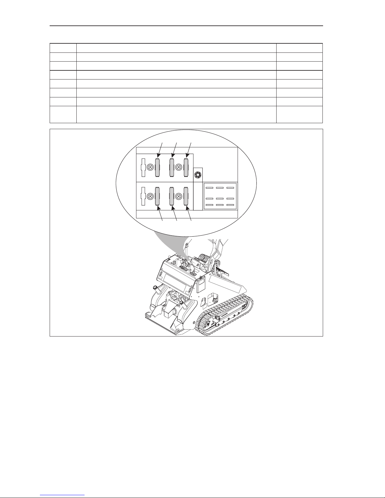
Routine Service and Maintenance
4.25
Figure 4-25 Fuse Panel
15
15
1
3
3
6
43
512
1
All fuses and their locations are shown in illustration Figure 4–25.
Fuse Circuit Amp Rating
1 Voltage Regulator 3
2 Crawl Speed Solenoid 3
3 Hydraulic Oil Cooler Fan 15
4 Fuel Solenoid 15
5 Hour Meter 1
6 Indicator Gauges 1
7 In-line Starter Solenoid Fuse (not shown in illustration - located in the RED
power line between the ignition switch and the starter motor.)
30
Page 79
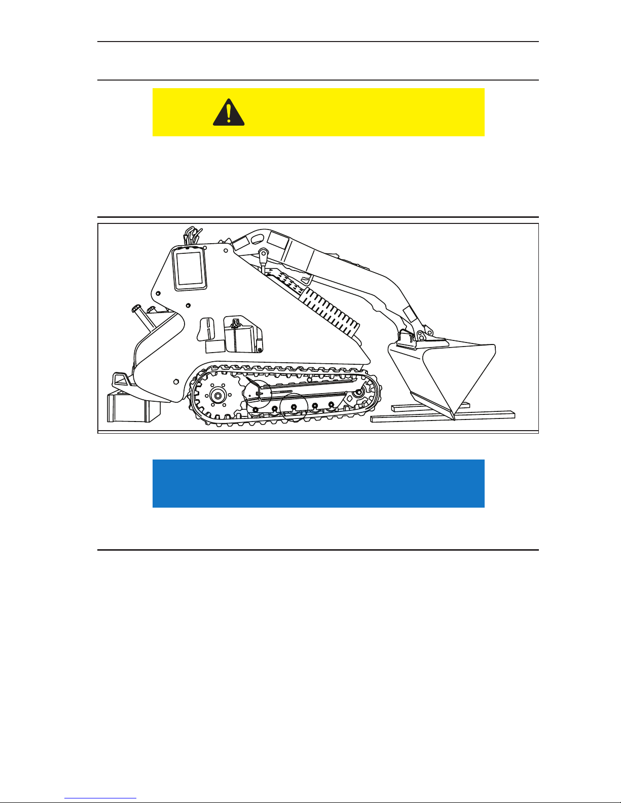
Routine Service and Maintenance
4.26
Track and Tension System Installation
1. Securely elevate the machine. See Figure 4–26 and Track Tensioning instructions.
• Make sure that the machine has been securely elevated and that there is no
danger of it tipping before beginning this procedure.
• To fully stabilize the machine, it may be necessary to insert an additional support
at the front of the machine, under the hydraulic tank. When this support has
been installed, raise the boom.
Figure 4-26 Machine Elevation
If any of the track tensioning components have come out of the track tension assembly when
the track came off of the machine, proceed to Step 2. If not, skip to Step 7.
2. Fully extend the track assemblies.
3. Shut off the engine.
4. Install tension bolt and thrust washer (Item 1, Figure 4–27) into track frame.
NOTE: Make sure that the thrust plate is rotated as far backwards as possible on
the tension bolt, releasing all track tension.
5. Install tension spring (Item 2, Figure 4–27) into track frame.
6. Install idler wheel (Item 3, Figure 4–27) assembly into track frame.
NOTE:
• Make sure that the idler wheel assembly is installed so that the axle bolt head is visible
and that the lower edge of the idler wheel aligns with the lower edge of the idler rollers.
• Make sure to slide the tension system components as far back into the track frame as
possible.
CAUTION
NOTICE
Page 80
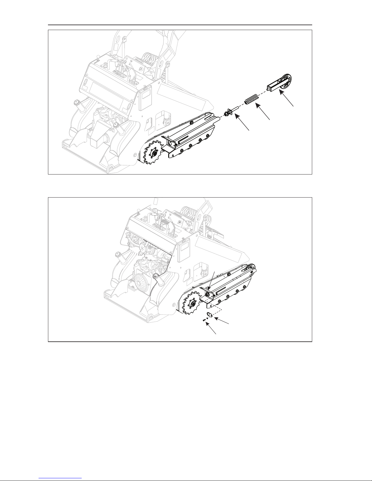
Routine Service and Maintenance
4.27
Figure 4-27 Track Drive Components Installed
7. Move rubber track away from the machine.
Figure 4-28 Remove Lock Plate
8. Remove track tension lock plate bolt (Item 1, Figure 4–28) using a 9/16” wrench
9. Remove lock plate (Item 2, Figure 4-28)
10. Loosen track tension by rotating the tension bolt (Item 3, Figure 4–28)
CLOCKWISE using a 1 5/8” wrench.
NOTE: On recent models, the track tension wrench is located under the
removable service access cover.
1
2
3
1
2
3
Page 81
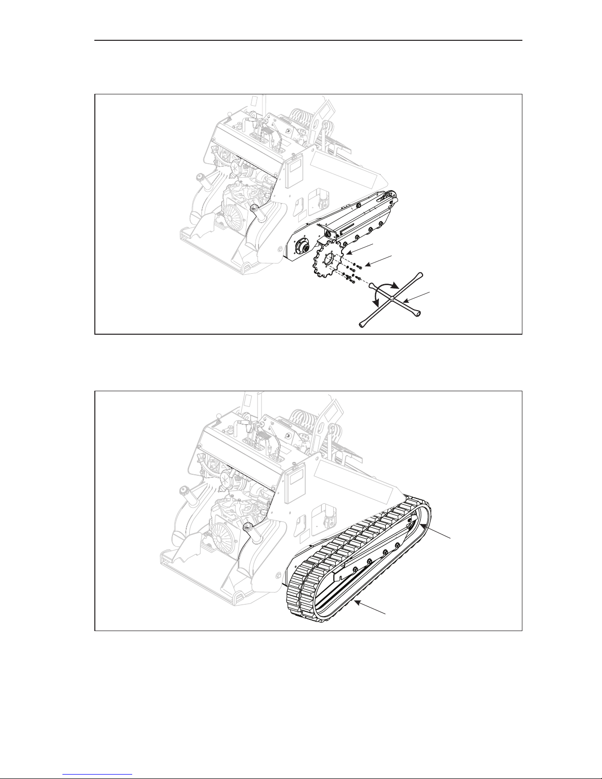
Routine Service and Maintenance
4.28
11. Using a ¾” wrench (or tire cross) (Item 1, Figure 4–29), remove the 6 bolts (Item
2, Figure 4-29) securing the drive sprocket (Item 3, Figure 4–29) to the drive
motor.
Figure 4-29 Remove Drive Sprocket
12. Slide the track (Item 2, Figure 4–30) on the front idler wheel (Item 1, Figure 4–30)
making sure that the track lugs are on each side of the idler wheel.
Figure 4-30 Install track onto front idler wheel
3
2
1
2
1
Page 82
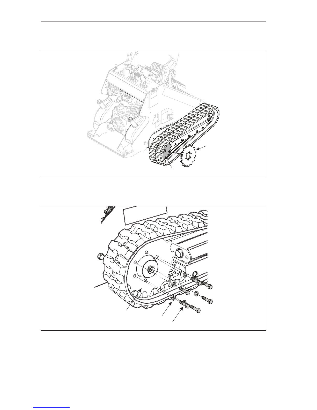
Routine Service and Maintenance
4.29
13. Insert the drive sprocket (Item 1, Figure 4–31) into rear of the track (Item 2,
Figure 4–31), between the track lugs and with the sprocket teeth in the track
sprocket holes.
Figure 4-31 Insert Drive Sprocket into Track
14. Position the drive sprocket and the track onto the drive motor.
15. Rotate the drive sprocket (Item 1, Figure 4–32) and track to align the bolt holes.
Figure 4-32 Install Track and Drive Sprocket
16. Install and secure the 6 drive sprocket lock washers (Item 2, Figure 4–32) and
mounting bolts (Item 3, Figure 4–32).
2
1
1
2
3
Page 83
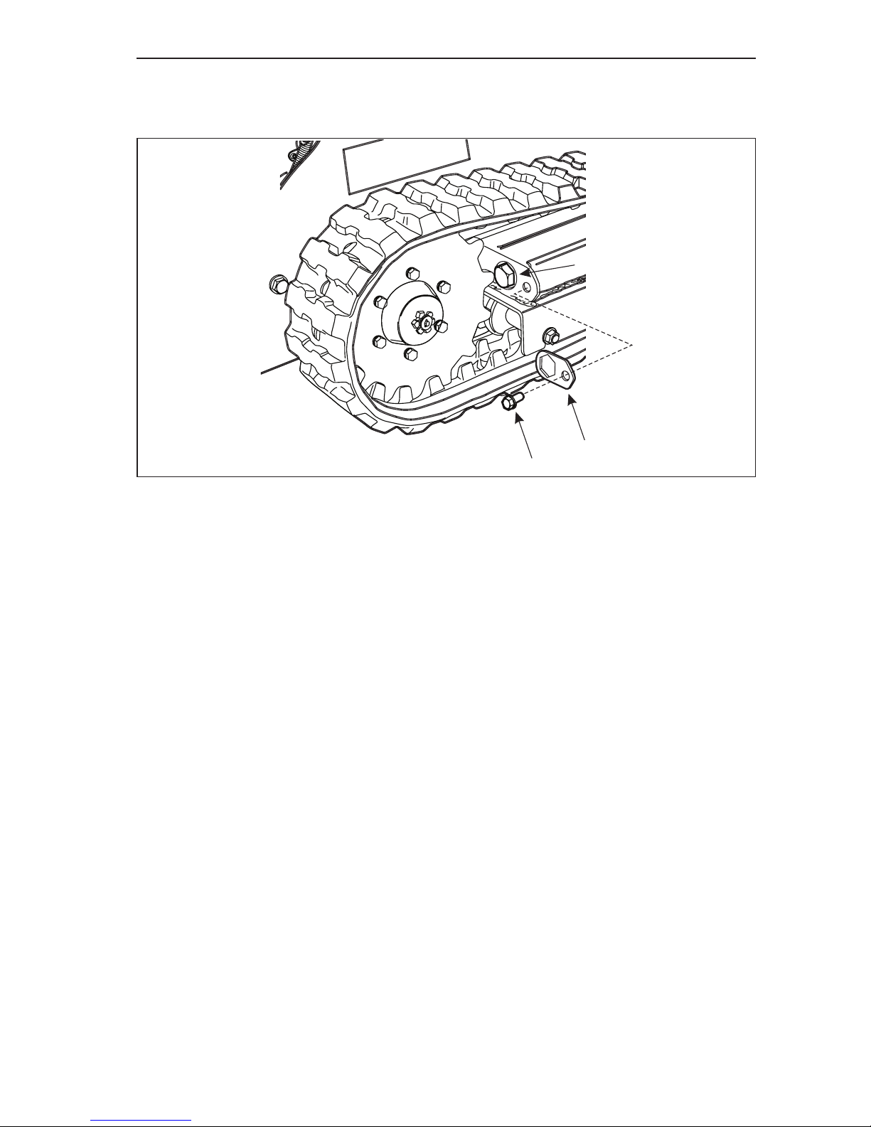
Routine Service and Maintenance
4.30
NOTE: Tighten the bolts evenly around the drive sprocket.
17. Rotate the tension bolt (Item 3, Figure 4–33) COUNTER CLOCKWISE until the
correct track tension is set. See Track Tensioning earlier in this manual.
Figure 4-33 Set Track Tension
18. Set Track Tension. Start the engine and slowly rotate the track forward and
backward to make sure that the track is properly seated on the drive sprocket.
19. Fully rotate the track forward and backward several times.
20. Shut off the engine.
21. Double check track tension. Adjust as needed.
22. Install track tension bolt lock plate (Item 2, Figure 4–33) and secure it with the
lock bolt (Item 1, Figure 4–33).
23. Return the machine to service.
3
2
1
Page 84

5.1
NOTICE
Problem Possible Causes Corrective Action
Starter does not turn the
engine over.
• Auxiliary hydraulics lever is
either in Forward or Reverse
position with no hydraulically
powered attachment installed.
• Move lever to neutral
position.
• Battery is dead. • Charge the battery.
• If battery does not hold a
charge, replace the battery.
• Electrical connections are
corroded or loose.
• Check electrical connections
for good contact.
• Remove cables from battery
terminals and fully clean
battery terminals and cable
clamps.
• If the cable clamps can not
be properly cleaned, replace
connectors.
• Relay or starter switch is
defective.
• Contact Authorized Service
Dealer.
• Engine is in hydraulic lock due
to a cylinder lled with fuel.
• Allow engine to cool before
attempting this procedure.
• Remove fuel injectors and
turn engine over to pump
excess fuel from engine
cylinder.
Section 5 - Troubleshooting
The following procedures will assist you in determining the potential cause of a machine
operating problem.
Make sure to follow all safety precautions stated in this manual when
doing any work on the machine.
Page 85

Troubleshooting
5.2
Problem Possible Causes Corrective Action
Engine will not start, starts
hard, or fails to keep running.
• Auxiliary hydraulics lever is
not in neutral position with
a hydraulically powered
attachment installed.
• Move lever to neutral
position.
• Fuel tanks are empty. • Fill fuel tanks with diesel fuel.
• Glow plugs not working. • Cycle glow plugs for about
10 seconds and try starting
engine.
• Air cleaner is dirty. • Clean air lter housing and
replace the lter elements.
• Injectors may be plugged • Have the diesel fuel injectors
serviced by your Authorized
Service Dealer.
• Air in fuel system. • Bleed air from fuel system.
See Kubota engine manual
for complete procedures and
see Section 4, Replacing
Fuel Filter for air bleed
instructions.
• Dirty or contaminated fuel lter. • Replace fuel lter.
• Dirt, water or stale fuel is in
fuel system.
• Drain fuel in tanks into
an appropriate storage
container and dispose of bad
fuel properly.
• Rell fuel tanks with fresh,
clean fuel.
• Replace fuel lter.
• 30 Amp fuse blown. • Replace fuse.
Engine loses power.
• Engine load is excessive. • Reduce ground speed.
• Reduce speed of
attachment.
• Air cleaner is dirty. • Clean air lter housing and
replace the lter elements.
• Engine oil level in crankcase
is low.
• Add the appropriate engine
oil to crankcase. See engine
manual for oil specications.
• Cooling ns and air passages
under engine blower housing
are plugged.
• Remove obstruction
from cooling ns and air
passages.
• Fuel injectors may be plugged
or dirty.
• Have the diesel fuel injectors
serviced by your Authorized
Service Dealer.
Page 86

Troubleshooting
5.3
Problem Possible Causes Corrective Action
Engine loses power.
• Dirty or contaminated fuel lter. • Replace fuel lter.
• Dirt, water, or stale fuel is in
fuel system.
• Drain fuel in tanks into
an appropriate storage
container and dispose of bad
fuel properly.
• Rell fuel tanks with fresh,
clean fuel.
• Replace fuel lter.
Engine overheats.
• Engine load is excessive. • Reduce ground speed.
• Reduce speed of
attachment.
• Engine oil level in crankcase
is low.
• Add the appropriate engine
oil to crankcase. See engine
manual for oil specications.
• Cooling ns and air passages
under engine blower housing
are plugged.
• Remove obstruction
from cooling ns and air
passages.
• Cooling system low on coolant • Check and rell coolant to
levels and with the type
of coolant indicated in the
engine manual.
• Dirty or plugged radiator • Clean the radiator.
Abnormal engine vibration.
• Engine mounting bolts are
loose.
• Tighten engine mounting
bolts.
With the machines engine
turned off, the boom creeps
downward more than 3” per
hour (less than 3” per hour
is normal for this machine).*
• Valve spool leakage. • Contact Service Dealer.
• Cylinder seals are leaking. • Replace cylinder seals.
With the machines engine
turned off, boom drops
downward quickly and then
stops.
• Cylinder seals are leaking. • Replace cylinder seals.
The machine does not
travel in either forward or
reverse directions.
• Engine is not running at full
speed.
• Advance throttle to full
engine speed.
• Hydraulic uid is cold. • Fully warm hydraulic uid.
• Hydraulic uid level is low. • Check and ll the hydraulic
uid tank with the
appropriate hydraulic uid.
• Fuel tanks are empty and
engine stops.
• Fill fuel tanks with fuel.
• If all above has been checked. • Contact authorized service
dealer.
*Tested with warm oil and no more than 530 lbs (240 Kg) in the bucket. Measure the
downward drop at the attachment lock pins on the back of the mount plate.
Page 87

Troubleshooting
5.4
Page 88
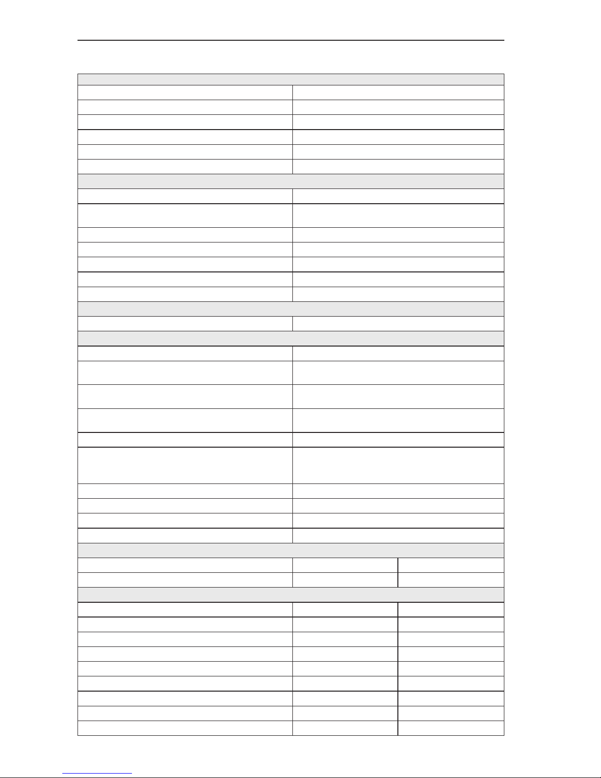
6.1
Section 6 - General Specications
Engine System
Type
Kubota D1105-E4B
Cooling System
Liquid Cooled
HP
24.8
Engine System - Intake
Normally Aspirated
Fuel Tank
4.5 Gallons (17-litre) per tank
Air Cleaner
Heavy-Duty Air Cleaner
Hydraulic System
Oil Cooling System
Air to oil cooler with electric fan
Pressure (Auxiliary/Boom & Tilt Cylinder
Circuit)
3000 psi (20684 kPa) system relief
Pressure Ground Drive Circuit
2600 psi (17926 kPa) system relief
Flow Auxiliary
14.5 GPM
Flow Ground Drive
Variable Flow 0 - 14.5 GPM
Reservoir Capacity
20 Gallons (76-litres)
Filter
10 Micron
Electrical System
Battery
12 Volt DC
Control System
Starting
Keyed ignition switch.
Steering
Two spring centered control lever with zero
turning type controls.
Boom/Loader Arms
Four position, spring centered lever
control. Up, neutral, down, and oat.
Bucket/Attachment Tilt
Three position, spring centered lever
control. Extend, neutral, and curl.
Auxiliary/Attachment Control
Three position, detent lever control.
Wheel/Track Options
9” (230mm) wide track with variable width
undercarriage from 34.5” - 43.5” (88 cm -
110.5 cm)
Drive Train
Douoble Gear Pump
Creep Control
Variable
Operator Platform
Spring Cushioned Stand On Platform
Mount Plate
Universal CUL Attachment Plate
Warranty
Engine Warranty
Two Year
Product Warranty
One Year
Ground Drive System-Dimensions
Units English Metric
Wheelbase
37 in. 940 mm
Ground Clearance
5.0 in. 127 mm
Overall Length (w/ Bucket)
96 in. 2440 mm
Overall Length (without Bucket)
77 in. 1956 mm
Overall Width (Fully Retracted)
35 in. 876 mm
Overall Width (Fully Extended)
43.5 in. 1105 mm
Overall Height
54 in. 1360 mm
Overall Operating Height (Fully Raised)
98 in. 2489 mm
Page 89

General Specications
6.2
Hinge Pin Height (Fully Raised)
76 in. 1930 mm
Units English Metric
Dump Height
60 in. 1524 mm
Ground Speed (Max)
3.0 mph 4.83 kph
Dump Angle
37 deg. 37 deg.
Reach
34 in. 864 mm
Tip Capacity
2100 lb. 952.5 kg
Operating Capacity, 35% of tip load.
735 lb. 333.5 kg
Operating Capacity, 50% of tip load.
1,050 lb. 476 kg
Weight (without Bucket) (*w/Bucket)
2680 lb. 1214 kg
Ground Pressure
3.6 psi 0.2531 kg/cm
2
Page 90
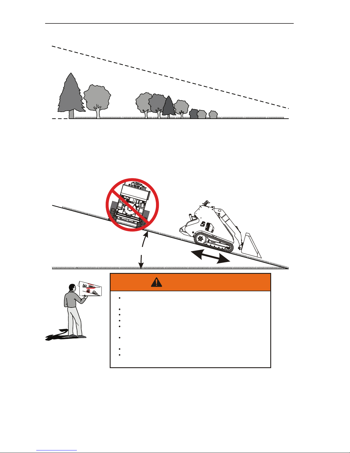
General Specications
6.3
SUGGESTED GUIDE FOR SIGHTING SLOPES FOR SAFE OPERATION
OF A COMPACT UTILITY LOADER WITH AN ATTACHMENT.
DO NOT REMOVE THIS PAGE FROM THE MANUAL.
1
6
15 DEGREES MAX.
1. Fold this page along dotted line indicated above. DO NOT remove the page
from the manual.
2. Hold page before you so that its left edge is vertically parallel toatree
trunk or other upright structure.
3. Sight across the fold in the direction of the hill slope you want to measure.
4. Compare the angle of the fold with the slope of the hill.
1
6
THI
S
ISA15
DE
G
REESLOPE
DONOTTRAVELACROSSORUPANDDOWN
ASLOPEGREATERTHAN15 DEGREES
To avoidserious injury, operate your unitup and down
thefaceofslopes.
Travel across slopes with great caution.
Do not operate on slopesgreater than 15 degrees.
Maketurns gradually to prevent tipping or loss of control.
Exerciseextreme caution when changing directionon
slopes.
Controlofthe machine maybeaffected by installed
attachments.
Reduce travel speedon slopes.
Read and understand allWarnings and Operating
Instructions in the Operator’s Manual.
WARNING
FOLD ALONG DOTTED LINE
DO NOT TRAVEL ACROSS OR UP AND DOWN
A SLOPE GREATER THAN 15 DEGREES.
THIS IS A 15 DEGREE SLOPE
Page 91

General Specications
6.4
Page 92

Manufactured by:
Phone: Morbark®, LLC.
Sales - 800-831-0042 8507 S. Winn. Rd., P.O. Box 1000,
Parts and Service - 800-255-8839 Winn, Michigan 48896
www.boxerequipment.com www.morbark.com
®
 Loading...