

Page 1

Baldwin Road Switchers
AS16, AS616, RS12
Bowser - Stewart Hobbies
PO Box 322
Montoursville PA 17754
www.bowser-trains.com
www.stewarthobbies.com
Part I
GENERAL INSTRUCTIONS AND TOOL SUGGESTIONS
Small Phillips & Flat Screwdrivers Pin Vise
Liquid Plastic Cement with Brush #57 Drill Bit
Cyanoacrilate Cement (ACC) Plastic Cutters
Modelers Knife Small Tweezers
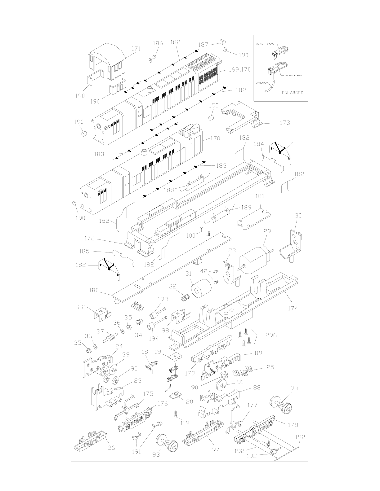
Note: Refer to the exploded view during assembly. The front, rear, left, and right
side of each unit is identified. Remove parts from the sprue carefully, verifying
that all gate material has been removed. Glue must be applied sparingly from the
inside of the shell, allowing capillary action to draw the cement into the joint or
hole.
Part II
SUPERSTUCTURE ASSEMBL Y
Step (1). The hood (1 or 2), cab (3) and the deck (4 or 5) are snapped together
and fastened to the chassis with two screws (66). Remove each screw (66) to
separate the superstructure from the chassis.
Step (2). Begin to separate the superstructure by removing the cab (3). Unsnap
the hood (1 or 2) from the deck (4 or 5).
Step (3). Refer to the exploded view diagram to install appropriate handrails and
lift bars (39 – 50) using the provided mounting holes.
Step (4). Choose a location for the horn (51). Drill a hole using the pin vise and
#57 drill bit. Apply cyanoacrilate (ACC) glue to the stem of the horn. Install the
horn into the hole.
Step (5). AS16 / 616 ONLY: Install the bell (52) using ACC glue in the notch
provided at the front of the hood (1).
Step (6). Install the cab glass (57 & 58).
Step (7). AS16 / 616 ONLY: Install the short headlight lens (55) into the front of
the body (1), and the long headlight lens (56) into the rear of the body (1). Install
each from the outside after noting the front and rear orientation on the exploded
view instruction sheet.
Step (8). RS12 ONLY: Install the long headlight lens (56) into the front of the
body (1), and the short headlight lens (55) into the rear of the body (1). Install
each from the outside after noting the front and rear orientation on the exploded
view instruction sheet.
Step (3). Place the assembled superstructure over the powered chassis. Note: The
frame (6) must be properly oriented to allow the deck (4 or 5) to seat properly .
Refer to the exploded view diagram. Notice that the rear of the frame (6) has
an extension of metal that is not present in the front of the piece. Also, note the
front and rear orientation of the hood (1 or 2). Turn the assembly upside down
and place on a padded flat surface. Assemble the coupler (63) or select the X2F
(67) and place it into the coupler box (64) and install the coupler lid (65). Slide the
coupler assembly into the opening of the pilot. Install using the provided screw
(66). Note: Do not use the shallow coupler boxes that are enclosed in the hand-
rail parts bag. They are used for a different version of this model. Only use the
parts as shown on the exploded view drawing to install the couplers.
Step (4). Press the air tanks (53 & 54) into the receptacles on the underside of the
deck (4 or 5).
Part IV
GENERAL INFORMATION
Painting Truck Sideframes
Modelers who wish to paint or weather truck sideframes (18, or 28 & 29) may wish
to remove them to prevent paint over spray from impairing electrical pickup. Begin
disassembly by removing the each screw (38) that hold the circuit board (35 or 36)
in place. Rotate the circuit board for access to the worm housing (20 or 31). Each
worm housing has two legs extending inward. Release the housings by prying the
legs outward with a small flat screwdriver. Disconnect the connector wires (17 or
27) from the Molex connectors on the underside of the circuit board by sliding the
Molex housing toward the middle of the board. Pull lightly on the wire if necessary
using a needle nosed pliers. The worm gear assembly (32, 33, 34, 71) and universal shaft (69 or 70) can be removed by prying upward with a small flat screwdriver.
The frame (6) can now be lifted upward and away from the trucks. The sideframes
are locked in place by a retainer clip (19 or 30). Four tabs extend upward from this
clip. These tabs are only visible when viewing the truck from directly overhead.
The retainer clip can be removed by gently prying outward on the tabs. Sideframes
can now be pulled away.
DCC Information
For DCC users, a DCC compatible plug socket has been provided. Remove the
DCC Plug (37) from the main circuit board (35 or 36). Reference your DCC manual
for proper decoder installation.
Detailing
RS12 ONLY: Drill bit starter guides have been placed at various locations on the
shell for Detail Associates #2202 Grab Irons (not included).
Note: Our models are very close in appearance to the Baldwin DRS-4-4-1500 (similar
to AS16), DRS-4-4-1000 (similar to RS12), and the DRS-6-4-1500 (similar to the
AS616).
Questions or Problems
We hope that you will be happy with this finely detailed kit. If any questions or
problems occur, please inform us. Any problems with defective parts will be responded to promptly.
Step (9). Snap the hood (1 or 2) into the deck (4 or 5). Slide the cab (3) into place
over the hood (1 or 2). Place the ends of the handrails (44,45) into the holes in the
cab rear. Note: If you do not see holes for the handrails on the cab rear, then the
cab is installed backward.
Part III
FINAL ASSEMBLY
Step (1). AS16 & RS12 ONLY: Install each brake cylinder (59) into the holes in the
sideframes (18). The use of cyanoacrilate (ACC) cement is optional.
Step (2). AS616 ONLY: Install each brake cylinder (60), brake arm (61), and brake
rod (62) into the provided holes in the sideframes (28). The use of cyanoacrilate
(ACC) cement is optional.
Page 2
11-04
REAR
REAR
BALDWIN AS16, AS616, RS12
FRONT
LEFT SIDE
FRONT
RIGHT SIDE
 Loading...