


SERVICE GUIDE
Ser vice Guide • Aaron 2250 |
i |

This Service Guide and the equipment it describes are for qualified technicians who maintain and repair the Aaron 2250 Electrosurgical Generator. Additional User information is available in the Aaron 2250 User’s Guide.
This document covers technical descriptions of the Aaron 2250 including its physical appearance, all operator controls and indications, operational specifications, component functional descriptions (module level), diagrams of the electronic circuits used, and troubleshooting guidelines (with chart comparisons).
The Aaron 2250 was constructed with the highest quality components, and was built in an ISO 9001 registered environment. In the unlikely event that your generator fails within one year of purchase date, Aaron Medical will warranty the product and effect factory repairs. Please refer to Appendix A Warranty for what is covered, length of coverage, and Obtain a Return Authorization Number in Section 8.
Equipment Covered in this Manual
Aaron 2250:
Reference No: A2250
For Information Contact
Aaron Medical • 7100 30th Ave. N. • St. Petersburg, FL 33710-2902
U.S. Phone 1-800-537-2790 Fax 1-800-323-1640 • International Phone +1-727-384-2323 Fax +1-727-347-9144 www.aaronmed.com • sales@aaronmed.com
EC Representative: Crownhouse
Hornbeam Square North
Harrogate, HG2 8PB UK
Phone 01423 870 998
Made in USA
Printed in USA
©2003 Aaron Medical. All rights reserved. Contents of this publication may not be reproduced without the written permission of Aaron Medical.
ii |
Aaron Medical |

SAFETY PRECAUTIONS WHEN OPERATING THE GENERATOR
The safe and effective use of electrosurgery depends to a large degree on factors solely under the control of the operator. There is no substitute for a properly trained and vigilant medical staff. It is important that they read, understand, and follow the operating instructions supplied with this electrosurgical equipment.
To promote the safe use of the Aaron 2250, please refer to the User’s Guide for standard operating precautions.
APPLICABLE SAFETY STANDARDS
CSA C22.2, NO. 601.1 - M90
UL 2601 - 1 - UL
IEC 60601 - 2 - 2 (2001-09) Part 1-2
CENELEC EN 60601 - 1 Part 1
IEC 60601 - 2 - 2 (1998-09) Part 2-2
IEC 60601 - 1 Part 1
CONVENTIONS USED IN THIS GUIDE
WARNING:
Indicates a potentially hazardous situation which, if not avoided, could result in death or serious injury.
CAUTION:
Indicates a hazardous situation which, if not avoided, may result in minor or moderate injury.
NOTICE:
Indicates an operating tip, a maintenance suggestion, or a hazard that may result in product damage.
Ser vice Guide • Aaron 2250 |
iii |

TABLE OF CONTENTS
Equipment Covered in this Manual............................................................................. |
ii |
For Information Contact .............................................................................................. |
ii |
Safety Precautions When Operating the Generator .......................................................... |
iii |
Applicable Safety Standards .............................................................................................. |
iii |
Conventions Used in this Guide......................................................................................... |
iii |
The Aaron 2250...................................................................................................................... |
1-1 |
Functional Description..................................................................................................... |
1-2 |
Unit Description ............................................................................................................... |
1-3 |
Safety Precautions When Repairing the Generator........................................................ |
1-3 |
General Warnings, Cautions, and Notices .............................................................. |
1-3 |
Active Accessories................................................................................................... |
1-4 |
Fire / Explosion Hazards ......................................................................................... |
1-4 |
Generator Electric Shock Hazards .......................................................................... |
1-5 |
Servicing.................................................................................................................. |
1-5 |
Cleaning .................................................................................................................. |
1-5 |
Controls, Indicators, and Receptacles ................................................................................ |
2-1 |
Front Panel...................................................................................................................... |
2-2 |
Controls and Indicators Overview ................................................................................... |
2-3 |
Symbols on the Front Panel.................................................................................... |
2-4 |
Cut and Blend Controls ........................................................................................... |
2-5 |
Coag Controls.......................................................................................................... |
2-6 |
Bipolar Controls ....................................................................................................... |
2-7 |
Indicators ................................................................................................................. |
2-8 |
Power Switch and Receptacles............................................................................... |
2-9 |
Rear Panel .................................................................................................................... |
2-10 |
Symbols on the Rear Panel .................................................................................. |
2-10 |
Technical Specifications....................................................................................................... |
3-1 |
Performance Characteristics ........................................................................................... |
3-2 |
Input Power ............................................................................................................. |
3-2 |
Duty Cycle ............................................................................................................... |
3-2 |
Dimensions and Weight .......................................................................................... |
3-2 |
Operating Parameters ............................................................................................. |
3-2 |
Transport and Storage............................................................................................. |
3-2 |
Audio Volume .......................................................................................................... |
3-3 |
Return Electrode Sensing ....................................................................................... |
3-3 |
Low Frequency (50-60 Hz) Leakage Current.......................................................... |
3-3 |
High Frequency (RF) Leakage Current................................................................... |
3-4 |
Standards and IEC Classifications.................................................................................. |
3-4 |
Class I Equipment (IEC 60601-1) ........................................................................... |
3-4 |
Type CF Equipment (IEC 60601-1) / Defibrillator Proof.......................................... |
3-4 |
Drip Proof (IEC 60601-2-2) ..................................................................................... |
3-4 |
Electromagnetic Interference................................................................................... |
3-4 |
Electromagnetic Compatibility (IEC 60601-1-2 and IEC 60601-2-2) ...................... |
3-4 |
Voltage Transients (Emergency Generator Mains Transfer) ................................... |
3-4 |
Output Characteristics..................................................................................................... |
3-5 |
Maximum Output for Monopolar and Bipolar Modes .............................................. |
3-5 |
Output Power Curves .............................................................................................. |
3-6 |
Output Waveforms................................................................................................... |
3-9 |
iv |
Aaron Medical |

Theory Of Operation ............................................................................................................. |
4-1 |
Block Diagram ................................................................................................................. |
4-2 |
Functional Overview of Key Circuits ............................................................................... |
4-2 |
Controls and Indicators ........................................................................................... |
4-2 |
Activation Sense Circuits (5) .................................................................................. |
4-2 |
Temperature Sensing Circuits (3)............................................................................ |
4-3 |
Neutral Electrode Monitoring Circuit (NEM) ............................................................ |
4-3 |
Footswitch Sensor Circuits (2) ............................................................................... |
4-3 |
Input Voltage............................................................................................................ |
4-3 |
Display Control Circuits ........................................................................................... |
4-3 |
Control Circuit.......................................................................................................... |
4-4 |
Power Factor Correction Circuit (PFC) ................................................................... |
4-4 |
Power Supply .......................................................................................................... |
4-4 |
Switch Mode Power Supply Circuit (SMPS)............................................................ |
4-4 |
Auxiliary Relay ........................................................................................................ |
4-4 |
Speaker Circuit ....................................................................................................... |
4-4 |
RF Drive ................................................................................................................. |
4-4 |
HV Relay ................................................................................................................. |
4-4 |
Output...................................................................................................................... |
4-4 |
Sense and Backup Sense Circuits.......................................................................... |
4-4 |
Controls and Indicators ................................................................................................... |
4-5 |
Aaron 2250 Control Signal Inputs and Outputs .............................................................. |
4-5 |
Operating the Aaron 2250 .................................................................................................... |
5-1 |
Inspecting the Generator and Accessories ..................................................................... |
5-2 |
Service Personnel Safety ................................................................................................ |
5-2 |
Installation and Placement .............................................................................................. |
5-3 |
Functional (Operational) Checks..................................................................................... |
5-3 |
Operating the Unit ................................................................................................... |
5-3 |
Preparing for Monopolar Surgery ............................................................................ |
5-4 |
Applying the Return Electrode................................................................................. |
5-4 |
Connecting Accessories .......................................................................................... |
5-4 |
Preparing for Bipolar Surgery.................................................................................. |
5-4 |
Activating the Unit ........................................................................................................... |
5-5 |
Maintaining the Aaron 2250 ................................................................................................. |
6-1 |
Cleaning .......................................................................................................................... |
6-2 |
Periodic Inspection .......................................................................................................... |
6-2 |
Fuse Replacement .......................................................................................................... |
6-2 |
Fuse Replacement on the Main PCB.............................................................................. |
6-3 |
Main PCB Fuse Information .................................................................................... |
6-3 |
Troubleshooting .................................................................................................................... |
7-1 |
Recommended Equipment for Troubleshooting.............................................................. |
7-2 |
Troubleshooting the Aaron 2250 ..................................................................................... |
7-2 |
Inspecting the Generator......................................................................................... |
7-2 |
Inspecting the Receptacles ..................................................................................... |
7-2 |
Inspecting Internal Components.............................................................................. |
7-3 |
Understanding Error Codes and Audio Tones................................................................. |
7-4 |
Correcting Common Problems ........................................................................................ |
7-5 |
Main Board Test Points ................................................................................................... |
7-9 |
Display Board Test Points ............................................................................................... |
7-9 |
Ser vice Guide • Aaron 2250 |
v |

Repair Policy and Procedures ............................................................................................. |
8-1 |
|
Responsibility of the Manufacturer.................................................................................. |
8-2 |
|
Returning the Generator for Service ............................................................................... |
8-2 |
|
Step 1 |
– Obtain a Returned Goods Authorization Number..................................... |
8-2 |
Step 2 |
– Clean the Generator ................................................................................. |
8-2 |
Step 3 |
– Ship the Generator ................................................................................... |
8-2 |
Warranty ................................................................................................................................ |
|
A-1 |
Board Drawings, schematics, & Assemblies ..................................................................... |
B-1 |
|
How to Order Parts from Aaron Medical......................................................................... |
B-2 |
|
Aaron 2250 Design Breakdown and Drawing Reference ............................................... |
B-2 |
|
Aaron Drawing and Schematic Package ........................................................................ |
B-4 |
|
LIST OF FIGURES
Figure 2 – 1 |
Layout of controls, indicators, and receptacles on the front panel.................. |
2-2 |
Figure 2 – 2 |
Controls for the Cut and Blend modes ............................................................ |
2-5 |
Figure 2 – 3 |
Controls for the Coag mode ............................................................................ |
2-6 |
Figure 2 – 4 |
Controls for the Bipolar mode.......................................................................... |
2-7 |
Figure 2 – 5 |
Indicators for power, return electrodes, and footswitch control....................... |
2-8 |
Figure 2 – 6 |
Location of the unit power switch and front panel receptacles ....................... |
2-9 |
Figure 2 – 7 |
Layout of connectors and controls on the rear panel.................................... |
2-10 |
Figure 3 – 1 |
Output power vs impedance for Cut mode...................................................... |
3-6 |
Figure 3 – 2 |
Output power versus impedance for Blend mode, set at Minimum. ............... |
3-6 |
Figure 3 – 3 |
Output power versus impedance for Blend mode, set at Maximum ............... |
3-7 |
Figure 3 – 4 |
Output power vs impedance for Coagulation mode ........................................ |
3-7 |
Figure 3 – 5 |
Output power vs impedance for Fulguration mode ......................................... |
3-8 |
Figure 3 – 6 |
Output power vs impedance for Bipolar mode ................................................ |
3-8 |
Figure 3 – 7 |
Cut set to 200 W, at no load, open.................................................................. |
3-9 |
Figure 3 – 8 |
Cut set to 200 W, actual power 200 W at 300 ohm load ................................ |
3-9 |
Figure 3 – 9 |
Blend minimum set to 200 W, at no load, open ............................................ |
3-10 |
Figure 3 – 10 |
Blend minimum set to 200 W, actual power 200 W at 300 ohm load ........... |
3-10 |
Figure 3 – 11 |
Blend maximum set to 200 W, at no load, open ........................................... |
3-11 |
Figure 3 – 12 |
Blend maximum set to 200 W, actual power 200 W at 300 ohm load .......... |
3-11 |
Figure 3 – 13 |
Coagulation set to 120 W, at no load, open .................................................. |
3-12 |
Figure 3 – 14 |
Coagulation set to 120 W, actual power 120 W at 500 ohm load................. |
3-12 |
Figure 3 – 15 |
Fulguration set to 80 W, at no load, open ..................................................... |
3-13 |
Figure 3 – 16 |
Fulguration set to 80 W, actual power 80 W at 500 ohm load ...................... |
3-13 |
Figure 3 – 17 |
Bipolar set to 80 W, at no load ...................................................................... |
3-14 |
Figure 3 – 18 |
Bipolar set to 80 W, actual power set to 200 W load .................................... |
3-14 |
Figure 4 – 1 |
Functional Block Diagram of the Aaron 2250 system. .................................... |
4-2 |
Figure 6 – 1 |
Fuse holder...................................................................................................... |
6-2 |
Figure 6 – 2 |
Fuse location ................................................................................................... |
6-3 |
vi |
Aaron Medical |

BOARD DRAWINGS AND SCHEMATICS
Main Board Schematic Block Diagram ................................................................................... |
B-5 |
Power Factor Circuit ............................................................................................................... |
B-6 |
Power Supply Circuit .............................................................................................................. |
B-7 |
SMPS Circuit........................................................................................................................... |
B-8 |
Power Generator Circuit ......................................................................................................... |
B-9 |
High Voltage Relays Circuit .................................................................................................. |
B-10 |
Current / Voltage Sensors Circuit.......................................................................................... |
B-11 |
Current / Voltage Sensors (Backup) Circuit.......................................................................... |
B-12 |
Audio Amplifier Circuit........................................................................................................... |
B-13 |
Display Block Diagram.......................................................................................................... |
B-14 |
System Logic Circuit ............................................................................................................. |
B-15 |
Display Control Circuit .......................................................................................................... |
B-16 |
Neutral Electrode Monitoring Circuit ..................................................................................... |
B-17 |
Analog to Digital Converter Circuit ....................................................................................... |
B-18 |
Request Sense Hand Cut Circuit.......................................................................................... |
B-19 |
Request Sense Hand Coag Circuit....................................................................................... |
B-20 |
Request Sense Foot Cut Circuit ........................................................................................... |
B-21 |
Request Sense Foot Coag Circuit ........................................................................................ |
B-22 |
Request Sense Foot Bipolar Circuit ..................................................................................... |
B-23 |
Foot Monopolar Contact Circuit ............................................................................................ |
B-24 |
Foot Bipolar Contact Circuit.................................................................................................. |
B-25 |
Silkscreen for Main PCB for Component Locations ............................................................. |
B-26 |
Silkscreen for Top of Display PCB for Component Locations .............................................. |
B-27 |
Silkscreen for Bottom of Display PCB for Component Locations......................................... |
B-28 |
Silkscreen for Relay PCB for Component Locations............................................................ |
B-29 |
Final Assembly Overview...................................................................................................... |
B-30 |
Cabling in Assembly ............................................................................................................. |
B-31 |
Mechanical Front Panel Assembly........................................................................................ |
B-32 |
Mechanical Back Panel Assembly ........................................................................................ |
B-33 |
Cabling Back Panel Assembly .............................................................................................. |
B-34 |
Ser vice Guide • Aaron 2250 |
vii |

viii |
Aaron Medical |

THE AARON 2250
This section includes the following information:
●Functional Description
●Unit Description
●Safety Precautions when Repairing the Generator
CAUTIONS:
Read all warnings, cautions, and instructions provided with this generator before using.
Read the instructions, warnings, and cautions provided with electrosurgical accessories before using. Specific instructions are not included in this manual.
Ser vice Guide • Aaron 2250 |
1-1 |

FUNCTIONAL DESCRIPTION
The Aaron 2250 is a multipurpose electrosurgical generator for use in physician’s offices and surgi-centers. This unit offers unsurpassed performance, flexibility, reliability, and user convenience.
The Aaron 2250 includes digital technology. This new technology is evident in the self-checking circuitry and error code readouts. The unit offers monopolar and bipolar electrosurgical operations.
The following are Aaron 2250 key advantages and benefits:
•Power Capabilities
Up to 200 watts of pure cut in the Cut mode @ 300 Ω Up to 200 watts of Blend @ 300 Ω
Up to 120 watts of Pinpoint @ 500 Ω Up to 80 watts of Spray @ 500 Ω
Up to 80 watts of Bipolar @ 150 Ω
•Cut Mode
The cut mode gives the surgeon flexibility to cut all types of tissue without losing performance.
The Cut mode generates constant output power over a wide range of impedances. Refer to the Technical Specifications section of this guide.
•Blend with 10 Settings
The Blend mode is a combination of Cutting and Hemostasis. The 2250 gives the surgeon freedom to adjust the desired level of hemostasis. A setting of 1 is minimal blend with maximum cutting effect. A setting of 10 is maximum hemostasis (blend) with minimal cutting effect. This adjustment is easily achieved by a incremental
adjustment. Refer to Section 2, Controls, Indicators, and Receptacles, Cut and Blend Controls. The Blend mode improves the rate of targeted tissue desiccation without increasing the power delivered by the generator.
•Two levels of coagulation: Pinpoint and Spray
Pinpoint provides precise control of bleeding in localized areas.
Spray provides greater control of bleeding in highly vascular tissue over broad surface areas.
•Return electrode sensing and contact quality monitoring
The 2250 incorporates a return electrode contact quality monitoring system (Bovie NEM™). This system detects the type of return electrode: solid or split. The system also continually monitors the contact quality between the patient and the split return electrode. This feature is designed to minimize patient burns at the return electrode site.
•FDFS™ (Fast Digital Feedback System)
The FDFS™ (Fast Digital Feedback System) measures voltage and current at 5,000 times a second and immediately adjusts the power to varying impedance during the electrosurgical procedure. The unit’s digital technology senses and responds to changes in tissue and density. Unlike analog, this feature reduces the need to adjust power settings manually.
NOTICE:
The Bovie NEM™ system recommends that you use a split return electrode.
•Isolated RF output
This minimizes the potential of alternate site burns.
•Standard connectors
These connectors accept the latest monopolar and bipolar instruments. Refer to Section 2, Controls, Indicators, and Receptacles to learn more.
1-2 |
Aaron Medical |
•Self diagnostics
These diagnostics continually monitor the unit to ensure proper performance.
UNIT DESCRIPTION
The Aaron 2250 is a self-contained unit, consisting of the main enclosure and power cord. The main components incorporated in the generator include:
•Front Panel Components Power switch; membrane switches to control power output and mode selection; receptacles for connecting electrosurgical accessories; and indicators that show the current settings, patient return electrode status, and footswitch status.
•Rear Panel Components Volume control; bipolar and monopolar footswitch receptacles; power cable receptacleand fuse holder; equipotential grounding stud; and remote accessory receptacle.
•Internal Components Display board; main board; speaker board; relay board; power supply; and cables.
SAFETY PRECAUTIONS WHEN REPAIRING THE GENERATOR
Before servicing the Aaron 2250, it is important that you read, understand, and follow the instructions supplied with the generator. Also, be familiar with any other equipment used to install, test, adjust, or repair the generator.
General Warnings, Cautions, and Notices
WARNINGS:
Use the generator only if the self-test has been completed as described. Otherwise, inaccurate power outputs may result.
The instrument receptacles on this generator are designed to accept only one instrument at a time. Do not attempt to connect more than one instrument at a time into any given receptacle. Doing so will cause simultaneous activation of the generator.
CAUTIONS:
Do not stack equipment on top of the generator or place the generator on top of any electrical equipment. These configurations are unstable and/or do not allow adequate cooling.
Provide as much distance as possible between the electrosurgical generator and other electronic equipment (such as monitors). An activated electrosurgical generator may cause electrical interference with them.
Do not turn the activation tone down to an inaudible level. The activation tone alerts the surgical team when an accessory is active.
NOTICES:
If required by local codes, connect the generator to the hospital equalization (grounding) connector with an equipotential cable.
Connect the power cord to a wall receptacle having the correct voltage. Otherwise, product damage may result.
Ser vice Guide • Aaron 2250 |
1-3 |

Active Accessories
WARNINGS:
Shock Hazard - Do not connect wet accessories to the generator.
Shock Hazard - Ensure that all accessories and adapters are correctly connected and that no metal is exposed.
CAUTIONS:
Accessories must be connected to the proper receptacle type. In particular, bipolar accessories must be connected to the Bipolar Instrument receptacle only. Improper connection may result in inadvertent generator activation.
Set power levels to the lowest setting before testing an accessory.
NOTICE:
During bipolar electrosurgery, do not activate the generator until the forceps have made contact with the patient. Product damage may occur.
Fire / Explosion Hazards
WARNINGS:
Explosion Hazard – Do not install the generator in the presence of flammable anesthetics, gases, liquids, or objects.
Fire Hazard – Do not place active accessories near or in contact with flammable materials (such as gauze or surgical drapes). Electrosurgical accessories that are activated or hot from use can cause a fire. Use a holster to hold electrosurgical accessories safely away from personnel and flammable materials.
Fire Hazard – Do not use extension cords.
Fire Hazard – For continued protection against fire hazard, replace fuses only with fuses of the same type and rating as the original fuse.
1-4 |
Aaron Medical |

Generator Electric Shock Hazards
WARNINGS:
Connect the generator power cord to a properly grounded receptacle. Do not use power plug adapters.
Do not connect a wet power cord to the generator or to the wall receptacle.
To allow stored energy to dissipate after power is disconnected (caps discharge), wait at least five minutes before replacing parts.
Always turn off and unplug the generator before cleaning.
Do not touch any exposed wiring or conductive surfaces while the generator is disassembled and energized. Never wear a grounding strap when working on an energized generator.
When taking troubleshooting measurements use appropriate precautions such as using isolated tools and equipment, using the “one hand rule,” etc.
Potentially lethal AC and DC voltages are present in the AC line circuitry, high voltage DC circuitry, and associated mounting and heat sink hardware described in this manual. These potentials are not isolated from the AC line. Take appropriate precautions when testing and troubleshooting this area of the generator.
High frequency, high voltage signals that can cause severe burns are present in the RF output stage and in the associated mounting and heat sink hardware. Take appropriate precautions when testing and troubleshooting this area of the generator.
Servicing
CAUTIONS:
Read all warnings, cautions, and instructions provided with this generator before servicing.
The generator contains electrostatic-sensitive components. When repairing the generator, work at a static-control workstation. Wear a grounding strap when handling electrostatic-sensitive components, except when working on an energized generator. Handle circuit boards by their nonconductive edges. Use an anti-static container for transport of electrostatic-sensitive components and circuit boards.
Cleaning
NOTICE:
Do not clean the generator with abrasive cleaning or disinfectant compounds, solvents, or other materials that could scratch the panels or damage the generator.
Ser vice Guide • Aaron 2250 |
1-5 |

1-6 |
Aaron Medical |

CONTROLS, INDICATORS, AND RECEPTACLES
This section describes:
●The Front Panel
●Controls and Indicators Overview
●The Rear Panel
Ser vice Guide • Aaron 2250 |
2 - 1 |
FRONT PANEL
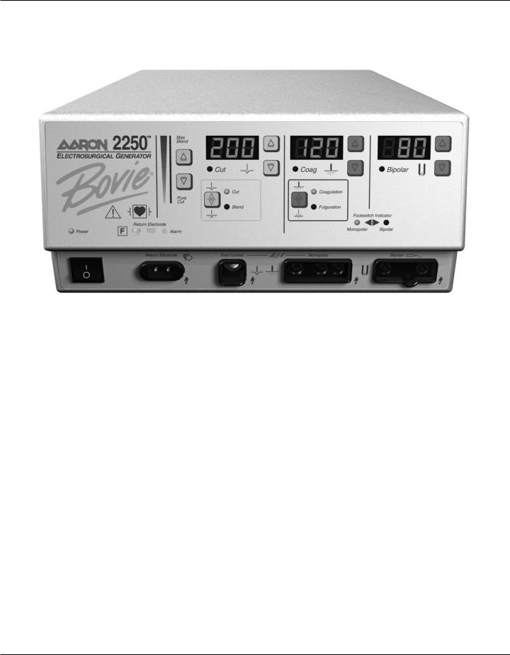
Figure 2 – 1 Layout of controls, indicators, and receptacles on the front panel
2 - 2 |
Aaron Medical |

CONTROLS AND INDICATORS OVERVIEW
Users may control most Aaron 2250 functions from the front panel. Each control is plainly marked and colored on the front panel for quick reference. The volume control is located on the rear panel.
Normal operations involve activating the generator with either a front connected handswitch or footswitch. The following components are the User Interface for the Aaron 2250.
Power Switch |
The rocker ON/OFF switch is located on the lower left |
|
corner allows the 2250 to be shut off when the unit is not |
|
in use. |
|
|
Watts Displays (Cut, Coag, and Bipolar) |
These large power output displays report the generator’s |
|
output power settings from 1 to 200 watts in the Cut |
|
mode, 1 to 120 watts in the Coag mode, and 1 to 80 watts |
|
in the Bipolar mode all in one, five, or ten watt incre- |
|
ments (at the rated load). During operation, the displayed |
|
number corresponds to the selected mode, indicating the |
|
available generator power to the surgeon. |
|
|
Membrane Power, Presets, |
The front panel overlay contains 10 membrane switches |
& Function Switches |
(sometimes called matrix switches). There is a membrane |
|
switch dedicated to each operational mode. These switches |
|
toggle the unit between functions (Cut, Blend, Coagula- |
|
tion, and Fulguration) and power settings (Cut, Coag, and |
|
Bipolar) in watts and blend settings indicated by a maxi- |
|
mum to minimum illuminated bar). |
|
|
Visual LED Indicators |
Mode LEDs illuminate for Cut, Coag, Bipolar, Cut , |
|
Blend, Coagulation, and Fulguration settings on the front |
|
of the unit. |
|
The footswitch LEDs illuminates to indicate that the |
|
monopolar or bipolar footswitch is connected to the unit. |
|
The Power LED indicates if the unit is switched On. |
|
The red Alarm LED indicates that the unit has detected |
|
an error or no return electrode is attached to the |
|
generator. |
|
The green Return Electrode LEDs indicate the type of |
|
return electrode sensed by the Bovie NEM™. |
|
|
Audible Indicators |
An activation tone sounds whenever the 2250 is activated. |
|
The volume may be adjusted up or down on the rear of |
|
the unit. |
|
An Alarm Siren sounds during all alarm conditions. The |
|
volume of this alarm cannot be adjusted. |
|
|
Ser vice Guide • Aaron 2250 |
2 - 3 |
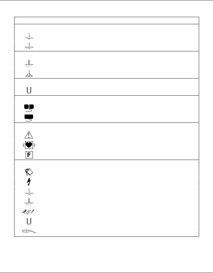
Symbols on the Front Panel
SYMBOLS DESCRIPTION
Cut Controls
Cut Mode
Blend Mode
Coag Controls
Coagulation Mode
Fulguration Mode
Bipolar Controls
Bipolar Mode
Indicators
Split Return Electrode
Solid Return Electrode
Regulatory Symbology
Read instructions before use.
Defibrillator proof type CF equipment
RF Isolated – patient connections are isolated from earth at high frequency.
Power Switch and Handpiece Connectors
Return Electrode Receptacle
Caution High Voltage
Cut Mode
Coag Mode
Monopolar Handpiece Receptacle
Bipolar Mode
Bipolar Handpiece Receptacle
2 - 4 |
Aaron Medical |
Cut and Blend Controls
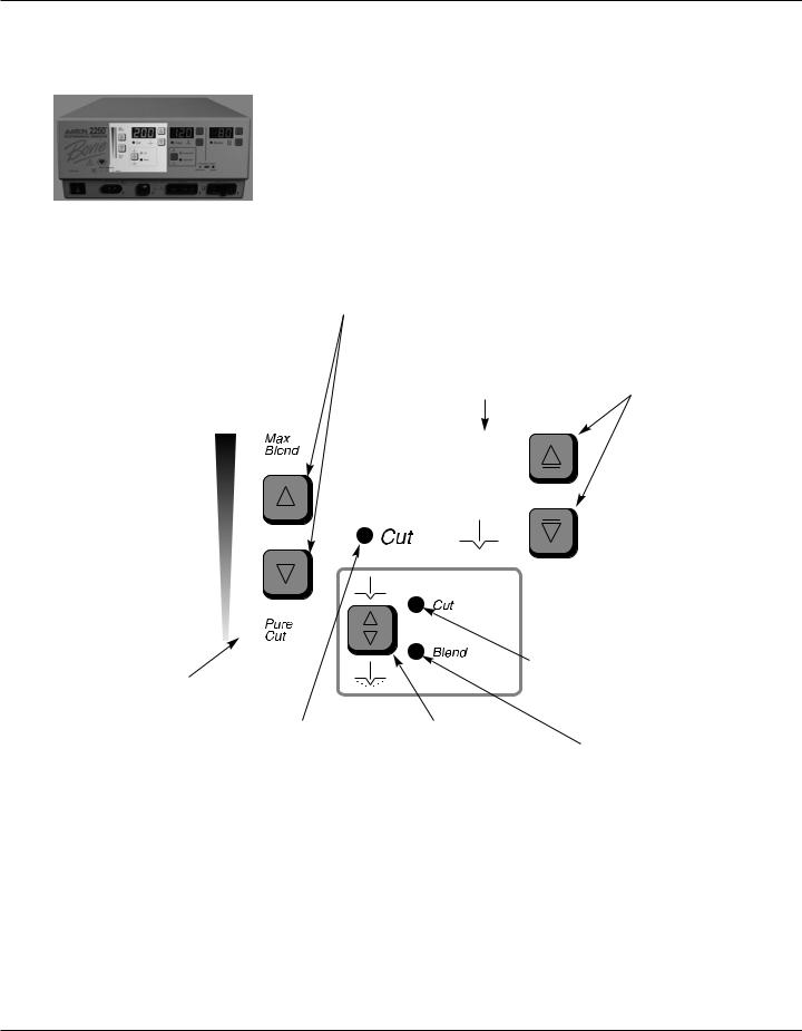
Figure 2 – 2 Controls for the Cut and Blend modes
Blend Amount Control Buttons
Increases or decreases the amount of blend (Level 1-10) added in the Blend mode.
Cut Power Display (watts)
Indicates the power set for the Cut / Blend mode.
Blend Amount Indicator
Indicates the amount of blend added in the Blend mode. More bars illuminated indicates more blend, divided into 10 steps.
|
|
|
|
|
|
|
|
|
|
|
|
|
|
|
|
|
|
|
|
|
|
|
|
|
|
|
|
|
|
|
|
|
|
|
|
|
|
|
|
|
|
|
|
|
|
|
|
|
|
|
|
|
|
|
|
|
|
|
|
|
|
|
|
|
|
|
|
|
|
|
|
|
|
|
|
|
|
|
|
|
|
|
|
|
|
|
|
|
|
|
|
|
|
|
|
|
|
|
|
|
|
|
|
|
|
|
|
|
|
|
|
|
|
|
|
|
|
|
|
|
|
|
|
|
|
Cut Activation Indicator |
Cut and Blend |
||||
Illuminates when Cut or |
Mode Selector |
||||
Blend mode is activated. |
Toggles between |
||||
|
|
|
|
|
Cut and Blend |
|
|
|
|
|
modes. |
Cut Power Control Buttons
Increases or decreases the Cut or Blend power output in increments of 1 to 10 watts.
Cut Mode Indicator
Indicates when the
Cut mode is selected.
Blend Mode Indicator
Indicates when the Blend mode is selected.
NOTICE:
When selecting the Blend mode, the unit defaults to a setting of minimum blend (only the first bar is illuminated).
Ser vice Guide • Aaron 2250 |
2 - 5 |
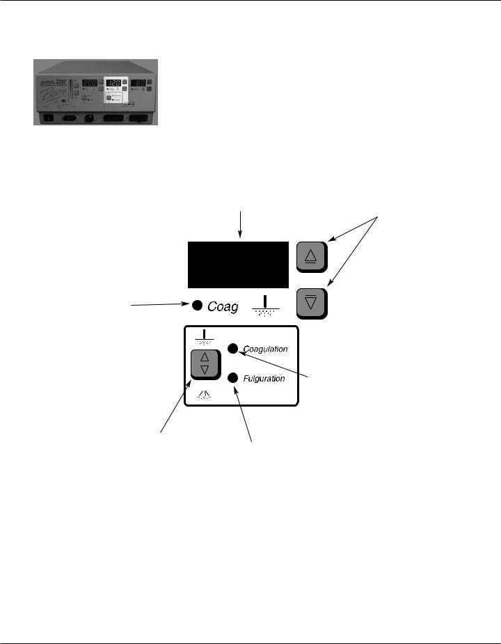
Coag Controls
Figure 2 – 3 Controls for the Coag mode
Coag Power Display (watts)
Indicates the power set for the Coag mode.
Coag Power Control Buttons
Increases or decreases the Coagulation or Fulguration Coag power output in increments of 1 to 10 watts.
Coag Activation Indicator
Illuminates when Coag mode is activated.
|
|
|
Coagulation Mode Indicator |
|
|
|
Indicates when the Coagulation |
|
|
|
mode is selected. |
|
|
||
|
|
|
|
Fulguration and |
|
|
|
Coagulation Mode |
|
|
|
Selector |
|
|
|
Toggles between |
|
Fulguration Mode Indicator |
|
Coagulation mode |
|
Indicates when the Fulguration |
|
and Fulguration mode. |
|
mode is selected. |
|
2 - 6 |
Aaron Medical |
Bipolar Controls
Figure 2 – 4 Controls for the Bipolar mode
Bipolar Power Display (watts)
Indicates the power set for the Bipolar mode.
Displays error code in the event of an error.
Bipolar Power Control Buttons
Increases or decreases the Bipolar power output in increments of 1 to 10 watts.
Bipolar Activation Indicator
Illuminates when Bipolar mode is activated.
Ser vice Guide • Aaron 2250 |
2 - 7 |
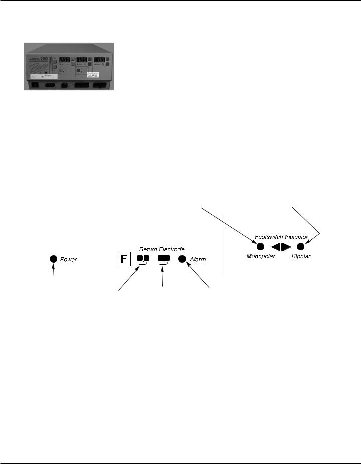
Indicators
Figure 2 – 5 Indicators for power, return electrodes, and footswitch control
Monopolar Footswitch Indicator
Illuminates when monopolar footswitch control is plugged in and available.
Bipolar Footswitch Indicator
Illuminates when bipolar footswitch control is plugged in and available.
Power Indicator
Illuminates when the main power is on.
Split Return |
Solid Return |
Alarm Indicator |
Electrode Indicator |
Electrode Indicator |
Illuminates when the system |
Illuminates when the |
Illuminates when the |
detects a return electrode |
system detects a |
system detects a |
alarm condition. |
split return electrode. |
solid return electrode. |
|
2 - 8 |
Aaron Medical |
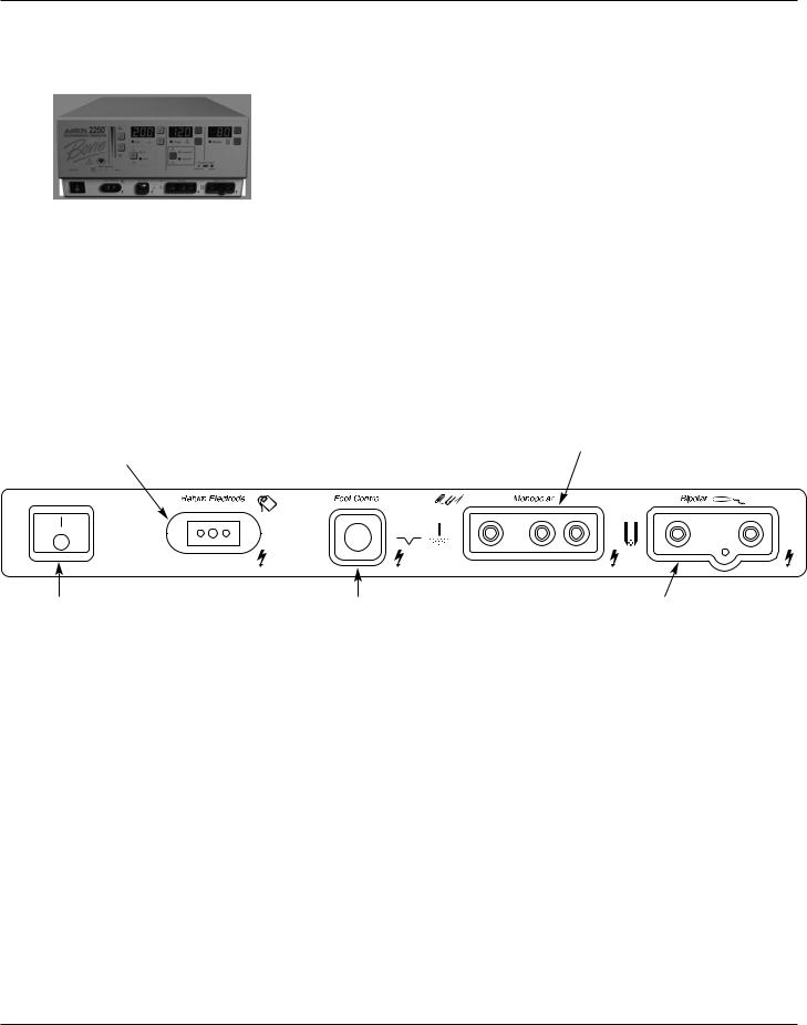
Power Switch and Receptacles
Figure 2 – 6 Location of the unit power switch and front panel receptacles
Return Electrode |
|
|
|
|
|
Monopolar Handswitching Receptacle |
|
Receptacle |
|
|
|
|
|
Accepts standard 3-pin handpieces. |
|
Accepts a standard |
|
|
|
|
|
Connect handswitching accessories. |
|
return electrode plug. |
|
|
|
|
|
|
|
|
|
|
|
|
|
|
|
|
|
|
|
|
|
|
|
|
|
|
|
|
|
|
|
Power On/Off Switch |
Monopolar Footswitching Receptacle |
Bipolar Receptacle |
Turns the unit on or off. |
Accepts cables or adapters equipped |
Accepts standard cables for |
|
with standard (Aaron #12) active plugs. |
bipolar handpieces. Connect |
|
Connect footswitching accessories. |
bipolar accessories. |
Ser vice Guide • Aaron 2250 |
2 - 9 |
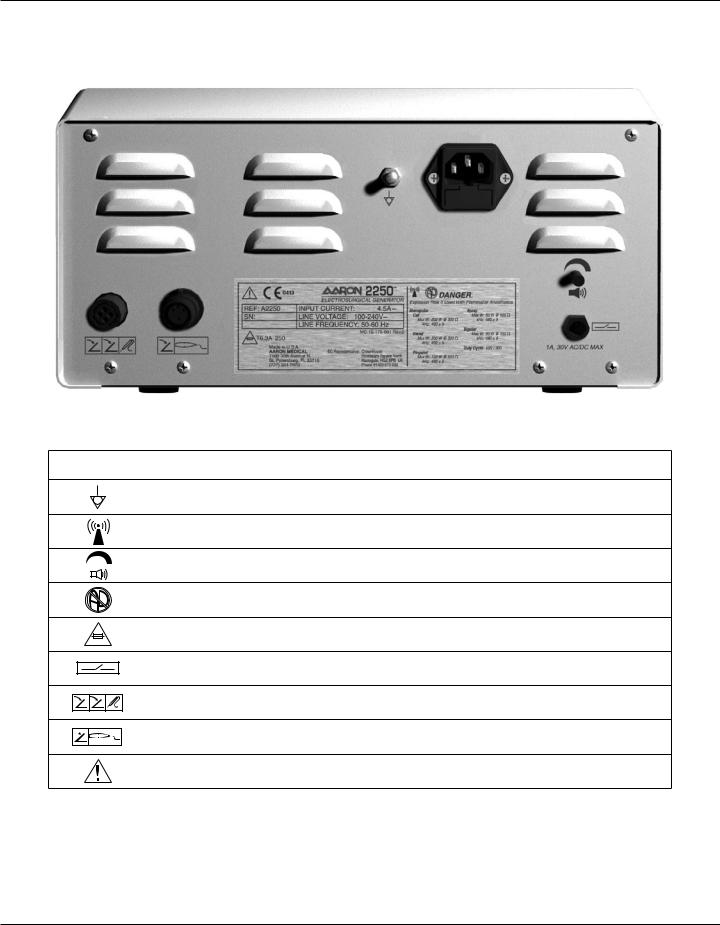
REAR PANEL
Figure 2 – 7 Layout of connectors and controls on the rear panel
Symbols on the Rear Panel
SYMBOLS DESCRIPTION
Equipotential Ground Stud
Non-ionizing Radiation
Volume Control
Danger - Explosion Risk If Used With Flammable Anesthetics.
Fuse Enclosed
Relay Connector
Monopolar Footswitch Input Jack
Bipolar Footswitch Input Jack
Read Instructions Before Use
2 - 1 0 |
Aaron Medical |

TECHNICAL SPECIFICATIONS
All specifications are nominal and subject to change without notice. A specification referred to as “typical” is within ± 20% of a stated value at room temperature (25° C / 77° F) and a nominal input power voltage.
Ser vice Guide • Aaron 2250 |
3 - 1 |

PERFORMANCE CHARACTERISTICS
Input Power
Input Voltage |
100-240 VAC |
|
|
Mains line frequency range (nominal): |
50 / 60 Hz |
|
|
Power consumption: |
500 VA |
|
|
Fuses (two): |
6.3 A (slow blow) |
|
|
Duty Cycle
Under maximum power settings and rated load conditions (Cut, 200 watt @ 300 ohm load), the generator is suitable for activation times of 10 seconds ON followed by 30 seconds OFF for one hour.
The internal temperature of the unit is continuously monitored. If the temperature rises above 850 C, the alarm will sound and output power will be deactivated.
Dimensions and Weight
Width |
31.1 cm (12.25 in.) |
Depth |
41.3 cm (16.25 in.) |
|
|
|
|
Height |
15.3 cm (6.0 in.) |
Weight |
< 8.75 kg (< 19 lbs) |
|
|
|
|
Operating Parameters
Ambient temperature range |
10° to 40° C (50° to 104° F) |
|
|
|
|
Relative humidity |
30% to 75%, non-condensing |
|
|
|
|
Atmospheric pressure |
700 to 1060 millibars |
|
|
|
|
Warm-up time |
If transported or stored at temperatures outside the operating temperature range, |
|
allow one hour for the generator to reach room temperature before use. |
||
|
||
|
|
Transport and Storage
Ambient temperature range |
-34˚ to 65˚ C (-29˚ to 149˚ F) |
|
|
Relative humidity |
0% to 75%, non-condensing |
|
|
Atmospheric pressure |
500 hPa to 1060 hPa |
|
|
Generator should fit on all standard Carts for monopolar generators. The device should be stored and used in a room temperature of approximately 770 F/250 C.
3 - 2 |
Aaron Medical |

Audio Volume
The audio levels stated below are for activation tones (cut, coag, and bipolar) and alarm tones (return electrode and system alarms) at a distance of one meter. Alarm tones meet the requirements for IEC 60601-2-2.
Activation Tone
Volume (adjustable) |
45 to 65 dB |
|
|
Frequency |
Cut: 1 kHz |
|
Blend: 1 kHz |
|
Coagulation: 2 kHz |
|
Fulguration: 2 kHz |
|
Bipolar: 2 kHz |
|
|
Duration |
Continuous while the generator is activated |
|
|
Alarm Tone
Volume (not adjustable) |
70 dB ± 5dB |
|
|
Frequency |
2 kHz 1⁄2 seconds / 1 kHz 1⁄2 seconds |
|
|
Duration |
2 seconds |
|
|
Return Electrode Sensing
The system presents audible and visible alarms when it senses no return electrode.
Trip resistance: 0 Ω to 5 Ω ± 3 Ω Continuous measurement:
Solid Once the system establishes the solid return electrode resistance, an increase of 20 Ω ± 5 Ω in resistance will cause an alarm. When the alarm condition exists, the system deactivates output power.
Trip resistance: 10 Ω ± 5 Ω to 135 Ω ± 10 Ω Continuous measurement:
Split Once the system establishes the split return electrode resistance, an increase of 40% in resistance will cause an alarm. When the alarm condition exists, the system deactivates output power.
Low Frequency (50-60 Hz) Leakage Current
Enclosure source current, ground open |
< 500 µA |
|
|
|
Normal polarity, intact ground: < 10 µA |
Source current, patient leads, all outputs |
Normal polarity, ground open: < 10 µA |
|
Reverse polarity, ground open: < 10 µA |
|
|
Sink current at high line, all inputs |
< 10 µA |
|
|
Ser vice Guide • Aaron 2250 |
3 - 3 |

High Frequency (RF) Leakage Current
Bipolar RF leakage current |
< 63 mA rms at 80 watts |
Monopolar RF leakage current (additional tolerance) |
< 150 mA rms |
|
|
STANDARDS AND IEC CLASSIFICATIONS
Class I Equipment (IEC 60601-1)
Accessible conductive parts cannot become live in the event of a basic insulation failure because of the way in which they are connected to the protective earth conductor.
Type CF Equipment (IEC 60601-1) / Defibrillator Proof
The Aaron 2250 provides a high degree of protection against electric shock, particularly regarding allowable leakage currents. It is type CF equipment. Patient connections are isolated from earth and resist the effects of defibrillator discharge.
Drip Proof (IEC 60601-2-2)
The generator enclosure is constructed so that liquid spillage in normal use does not wet electrical insulation or other components which, when wet, are likely to affect adversely the safety of the generator.
Electromagnetic Interference
When other equipment is placed on or beneath a Aaron 2250, the unit can be activated without interference. The generator minimizes electromagnetic interference to video equipment used in the operating room.
Electromagnetic Compatibility (IEC 60601-1-2 and IEC 60601-2-2)
The Aaron 2250 complies with the appropriate IEC 60601-1-2 and IEC 60601-2-2 specifications regarding electromagnetic compatibility.
Voltage Transients (Emergency Generator Mains Transfer)
The Aaron 2250 operates in a safe manner when the transfer is made between line AC and an emergency generator voltage source.
3 - 4 |
Aaron Medical |

OUTPUT CHARACTERISTICS
Maximum Output for Monopolar and Bipolar Modes
Power readouts agree with actual power into rated load to within 20% or 5 watts, whichever is greater.
|
|
|
|
|
Crest Factor* |
Mode |
Output Power |
Output Frequency |
Repetition Rate |
Vp-p max |
(Rated Load) |
|
|
|
|
|
|
Cut |
200 W @ 300 Ω |
490 kHz ± 5 kHz |
N / A |
2500 V |
1.6 ± 20% |
|
|
|
|
|
|
Blend (Max) |
200 W @ 300 Ω |
490 kHz ± 5 kHz |
30 kHz ± 5 kHz |
3300 V |
3.5 ± 20% |
|
|
|
|
|
|
Coagulation |
120 W @ 500 Ω |
490 kHz ± 5 kHz |
30 kHz ± 5 kHz |
3500 V |
4.5 ± 20% |
|
|
|
|
|
|
Fulguration |
80 W @ 500 Ω |
490 kHz ± 5 kHz |
30 kHz ± 5 kHz |
7000 V |
6.5 ± 20% |
|
|
|
|
|
|
Bipolar |
80 W @ 150 Ω |
490 kHz ± 5 kHz |
30 kHz ± 5 kHz |
1000 V |
1.6 ± 20% |
|
|
|
|
|
|
Ser vice Guide • Aaron 2250 |
3 - 5 |

Output Power Curves
The curves that follow depict the changes for each mode at specific power settings.
Figure 3 – 1 Output power vs impedance for Cut mode
Figure 3 – 2 Output power versus impedance for Blend mode, set at Minimum.
3 - 6 |
Aaron Medical |
 Loading...