

Page 1
I n t e rface Owner’s manual
Page 2
F i g u re 1
F i g u re 2
CASA™ I N T E R FA C E
O w n e r’s manual
E n g l i s h . . . . . . . . . . . . . . . . . . . . . . . . . . . . . . .2
F i g u re 3
F i g u re 4
Page 3
F i g u re 5
F i g u re 6
1
Page 4

SAFETY INSTRUCTIONS
C a u t i o n :
To reduce the risk of electric shock, do not
remove the back panel. No user- s e rv i c e a b l e
p a rts inside. Refer servicing to qualified
p e r s o n n e l .
Explanation of Graphical Symbols
The lightning flash within an equilateral triangle
is intended to alert you to the presence of uninsulated "dangerous voltage" within the pro d u c t ’s
e n c l o s u re that may be of sufficient magnitude to
constitute an electric shock to persons.
The exclamation point within an equilateral
triangle is intended to alert you to the pre s e n c e
of important operating and maintenance
( s e rvicing) instructions in the literature
accompanying the appliance
1 Read Instructions – All the safety and
operating instructions should be read before
the appliance is operated.
2 Retain Instructions – The safety and operating
i n s t ructions should be retained for future
re f e re n c e .
3 Heed Wa rnings – All warnings on the
appliance and in the operating instructions
should be adhered to.
4 Follow Instructions – All operating and use
i n s t ructions should be followed.
5 Water and Moisture – The appliance should
not be used near water – for example, near
a bathtub, washbowl, kitchen sink, laundry
tub, in a wet basement, or near a swimming
pool and the like.
6 C a rts and Stands – The appliance should be
used only with a cart or stand that is
recommended by the manufacture r.
7 Wall or Ceiling Mounting – The appliance
should be mounted to a wall or ceiling only
as recommended by the manufacture r.
8 Ventilation – The appliance should be
situated so that its location or position does
not interf e re with its proper ventilation. For
example, the appliance should not be
situated on a bed, sofa, rug, or similar
s u rface that may block the ventilation
openings; or placed in a built-in installation,
such as a bookcase or cabinet, that may
impede the flow of air through the ventilation
o p e n i n g s .
9 Heat – The appliance should be situated
away from heat sources such as radiators,
heat registers, stoves, or other appliances
that produce heat.
1 0 Power Sources – The appliance should be
connected to a power supply only of the
type described in the operating instructions
or as marked on the appliance.
1 1 The equipment must be grounded (earthed).
When using an extension power supply cord
or a power supply cord other than that
supplied, it should be 3-core, fitted with the
a p p ropriate moulded-on plug and carry
safety approval appropriate to the country
of use.
1 2 Power Cord Protection – Power-supply cords
should be routed so that they are not likely
to be walked on or pinched by items placed
on or against them, paying particular
attention to cords at plugs, convenience
receptacles and the point where they exit
f rom the appliance.
1 3 Cleaning – The appliance should be
cleaned only as recommended by the
m a n u f a c t u re r.
1 4 Non-use Periods – The power cord of the
appliance should be unplugged from
the outlet when left unused for a long
period of time.
1 5 Object and Liquid Entry – Care should be
taken so that objects do not fall and liquids
a re not spilled into the enclosure through
o p e n i n g s .
1 6 Damage Requiring Service – The appliance
should be serviced by qualified personnel
w h e n :
a The power-supply cord or the plug has
been damaged; or
b Objects have fallen, or liquid has been
spilled into the appliance; or
c T h e a p p l i a n c e h a s b e e n e x p o s e d t o r a i n ; o r
d The appliance does not appear to operate
n o rm a l l y, or exhibits a marked change in
p e rf o rmance; or
e The appliance has been dropped, or the
e n c l o s u re damaged.
1 7 S e rvicing – The user should not attempt to
s e rvice the appliance beyond that described
in the operating instructions. All other
s e rvicing should be re f e rred to qualified
s e rvice personnel.
Wa rn i n g s :
To prevent fire or shock hazard, do not expose
this equipment to rain or moisture .
O b s e rve all warnings on the equipment itself.
To avoid electrical shock, do not open the
e n c l o s u re. There are no user serviceable
p a rts inside. Refer all service questions to an
authorised B&W dealer.
To prevent electric shock, do not use this
(polarised) power plug with an extension cord
receptacle or other outlet unless the blades can
be fully inserted to prevent blade exposure .
E n s u re that the voltage indicated on the re a r
panel matches that of the power supply.
V E N T I L ATION – THE APPLIANCE SHOULD BE
S I T U ATED SO THAT ITS LOCATION OR
POSITION DOES NOT INTERFERE WITH ITS
PROPER VENTILATION:
A .FOR THE INTERFACE: ENSURE AT LEAST
2 INCHES (50 MM) OF UNRESTRICTED
AIR SPACE EITHER SIDE OF THE INTERFA C E
A N D 5 I N C H E S( 1 2 5 MM) OF
UNRESTRICTED AIR SPACE ABOVE
THE INTERFA C E .
B .FOR THE SPEAKERS: ENSURE AT LEAST 2
INCHES (50 MM) OF UNRESTRICTED AIR
S PACE IMMEDIAT E LY AROUND THE AREA OF
THE REAR OF THE LOUDSPEAKER BAFFLE.
ENSURE SUFFICIENT SPACING BETWEEN
CONNECTION CABLES AND SINGLE
I N S U L ATED MAINS CABLING.
DO NOT RUN CONNECTION CABLES
AND TELECOMMUNICATIONS OR
SINGLE INSULATED MAINS CABLING
IN THE SAME TRUNKING.
USE CONNECTOR PLUGS AND SOCKETS
WITH B&W APPROVED CASA COMPAT I B L E
EQUIPMENT ONLY.
DO NOT USE CONNECTOR PLUGS OR
SOCKETS TO CONNECT TO COMPUTER
OR TELEPHONY NETWORKS OR EQUIPMENT.
2
Page 5

I N T R O D U C T I O N
Thank you for choosing B&W.
The CASA™ Interface is designed to be used
with the range of Active CASA™ speakers and
o ffer a high quality, permanent audio installation.
B&W Loudspeakers has an outstanding
reputation for quality audio products. In
designing its CASA™ Interface B&W set
outstanding sound quality as an overr i d i n g
p r i o r i t y. Conventional installed speaker systems
use power amplifiers to drive remote passive
loudspeakers. This approach often limits the size
and scope of a system and its arc h i t e c t u re .
Remote powered speakers are one obvious
solution. However, the industry has avoided
p o w e red speaker systems because of the need
to install both power and signal cabling to each
s p e a k e r. There is an additional problem involved
with powered speakers in needing to switch
them on and off remotely through separate
c o n t rol wiring. The CASA™ Interface side-steps
these issues by using Active Speakers driven by
remote DC power. Output lines are driven in
balanced form by the Interface. This form of
working permits far longer cable runs than can
generally be provided in domestic audio systems
without loss of quality due to cable impedance
e ffects or interf e rence. The connection
re q u i rement is for five signals between Active
Speaker and Interface, namely two power, two
signal and a ground. The adoption of Category
5 shielded RJ-45 plugs and cables means the
CASA™ Interface relies on just one pro v e n
connector type and cabling, familiar from the
computer and telecommunications industries.
This neatly satisfies all re q u i rements for re l i a b i l i t y
and ease of installation. The provision of DC
power wiring to each Active Speaker gave the
CASA™ Interface design team an easy ro u t e
down which to run data from infra red (IR)
receivers in the speakers back to the central
C o n t ro l l e r. This IR data is carried at high
f requencies and ‘piggy backs’ the power
supply lines, eliminating the need for separate
c o n t rol conductors. Third - p a rty IR remotes send
back their IR data to the central Contro l l e r
t h rough this route. CASA™ & the CASA™
I n t e rface are the first domestic audio systems
to exploit the audiophile quality of true, in-wall
Active Speakers.
This manual is designed to help you install the
CASA™ Interface with CASA™ speakers. If you
intend to use the Interface in conjunction with the
CASA™ Controller you must consult the CASA™
Installation manual packed with the CASA™
C o n t ro l l e r. Please read this manual fully before
unpacking and installing the product. It will help
you to optimise its perf o rmance.
B&W maintains a network of dedicated
distributors who will be able to help you
should you have any problems your dealer
cannot re s o l v e .
We suggest you retain the packing for
f u t u re use.
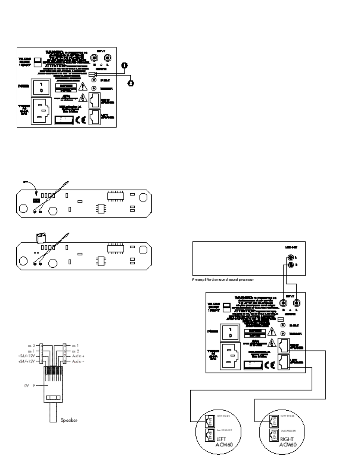
POWER & CONTROL
( F i g u re 1)
With the power switch on the rear of the
I n t e rface in the on position, the 3.5mm trigger
socket controls the unit’s power up/standby
status. This socket is configured by use of re a r
panel DIP switch (at the top and labelled as 1).
In the off (left) position the unit is normally on
and a +ve voltage of 5 –12v on the centre
pin of this socket will put the unit into standby.
Conversely with this switch in the on (right)
position the unit is normally in standby and a
+ve voltage of 5 –12v on the centre pin of this
socket will switch the unit on.
The second lower DIP switch (labelled as 2)
should be off (left) for the unit to be used without
the CASA™ Contro l l e r. In this (Master) mode,
audio from the RCA type phono inputs is pre s e n t
at the RJ-45 outputs. Conversely with the switch
on (right) audio from these sockets is not pre s e n t
at the RJ-45 outputs. This (Slave) mode is
re q u i red for connection of the Interface to a
CASA™ Contro l l e r.
The unit is shipped with both switches off (left)
and the unit set as Master and Normally on.
L O U D S P E A K E R S
AW M™7 0
The AWM™70 is a wall-mounted 100-watt
Active Speaker using a 7-inch Kevlar
bass/midrange driver and a 1-inch aluminium
dome tweeter. Two 100-watt channels of
amplification are provided to power the HF and
LF outputs of the active cro s s o v e r. Amplifier
power of this order re q u i res substantial
heatsinking which is provided both by a finned
rear extrusion and the ribbed baffle itself. The
c rossover has a damped 2nd-order network for
the bass/midrange unit and a 3rd - o rder slope
for the tweeter. Active equalisation is used to
enhance bass output and to perf o rm drive unit
c o rrection and phase compensation giving
smooth drive unit integration and good off - a x i s
f requency response. The crossover also feature s
overload and DC offset protection together with
a power-on mute sequence (not using relays) that
e n s u res power-up is free from clicks and thumps.
An IR receiver/modulator is mounted in the
bottom centre of the baffle. This receives IR
codes from remote control handsets and transmits
those codes back to the Interface by way of the
power supply. An LED telltale flashes to show
when an IR command has been received.
AW M ™ 6 5
The AWM™65 is a wall-mounted 50-watt
Active Speaker using a 6.5-inch Kevlar
bass/midrange driver and a 1-inch aluminium
dome tweeter. A high-quality passive crossover is
used to integrate the mid/bass driver and
t w e e t e r. An IR receiver/modulator is mounted in
the bottom centre of the baffle. This receives IR
codes from remote control handsets and transmits
those codes back to the Interface by way of
the power supply. An LED telltale flashes to
show when an IR command has been re c e i v e d .
®
®
A
C M ™ 6 0
The ACM™60 is a 20-watt, Active ceilingmounted speaker using a 165 mm
bass/midrange driver with a 25 mm co-axially
placed tweeter. No IR input is provided. Two RJ45 connectors (Controller and 2nd Speaker) are
p rovided which can be used to ‘daisy chain’ up
to five pairs of ACM™60s. See section Loading
Considerations for further details.
DISABLING IR
R E C E I V E R / M O D U L AT O R
( AWM™70/65 only)
( F i g u re 2)
If IR reception is a problem in a part i c u l a r
location it may be necessary to disable IR
reception on a speaker. Locate the IR board
behind the IR lens at the bottom of the rear
of the baffle. To disable the IR receiver
locate the jumper shown in the diagram below
and remove it taking care not to damage any
c o m p o n e n t s .
C A B L I N G
The CASA™ System and Interface are designed
to use shielded Category 5 cable with RJ-45
connectors (24 or 26 AWG with cert a i n
loading/distance considerations – 120 foot ru n s
for the AWM™70 for instance). Tw i s t e d - p a i r
cables comprise copper cores surrounded by an
insulator twisted together to form a pair. The
cable is a bundle of twisted pairs surrounded by
an insulator. Unshielded twisted pair cable (UTP)
is common in telephony applications but is
unsuitable for use in CASA™ installations.
Shielded twisted pair cable also (STP) off e r s
better cross-talk and interf e rence perf o rm a n c e .
The EIA/TIA 568 Commercial Building Wi r i n g
S t a n d a rd defines five categories of network
cabling. CASA™ is designed for shielded
C a t e g o ry 5 cable which is 100-ohm, four- w i re
twisted-pair cable (eight cores) certified to 100
Mbps (Mega bits per second) transmission rates
in network installations. The cable has low
capacitance and low cross-talk characteristics.
Of the eight cores available six (three pairs) are
dedicated to providing a low impedance supply
to the speakers. The remaining two cores carry
the audio signal. The high frequency IR data is
‘piggy backed’ on the DC power supply lines.
The screen of the shielded cable makes a ninth
connection. All cables and terminations must
c o n f o rm to specifications to eliminate cro s s - t a l k
and interf e rence problems. Old style connectors
and jacks are not suitable. Additionally, twists
in the cable pairs must be maintained up to the
connection point. One other cable characteristic
needs to be considered which relates to
w h e re the cable is installed. To comply with
the National Electrical Code (NEC), all cable
installed into the ceiling void (plenum space)
must be in metal conduit or must meet local
f i re codes. Two types of insulation are used:
3
Page 6

PVC (polyvinyl chloride) insulation for normal
use and fluoropolymer (Teflon) insulation for
plenumrated cable. We recommend the latter
for CASA™ in-wall and ceiling installations.
T h e re are no twists in the cables which are
w i red straight through. The only criterion is
that the pairs are adjacent, for example:
B rown is alongside Brown/White; Blue is
alongside Blue/White and Green is alongside
G reen/White, etc.
RJ-45 CONNECTOR PIN
ASSIGNMENT
( F i g u re 3)
The pin assignment for the RJ-45 connector
(Speaker connections):
Pin Signal C o m m e n t
1 +24/+12V 12V in Standby mode
2 –24/–12V 12V in Standby mode
3 as 1
4 as 2
5 as 1
6 as 2
7 + Audio
8 – Audio
9 0V S c re e n
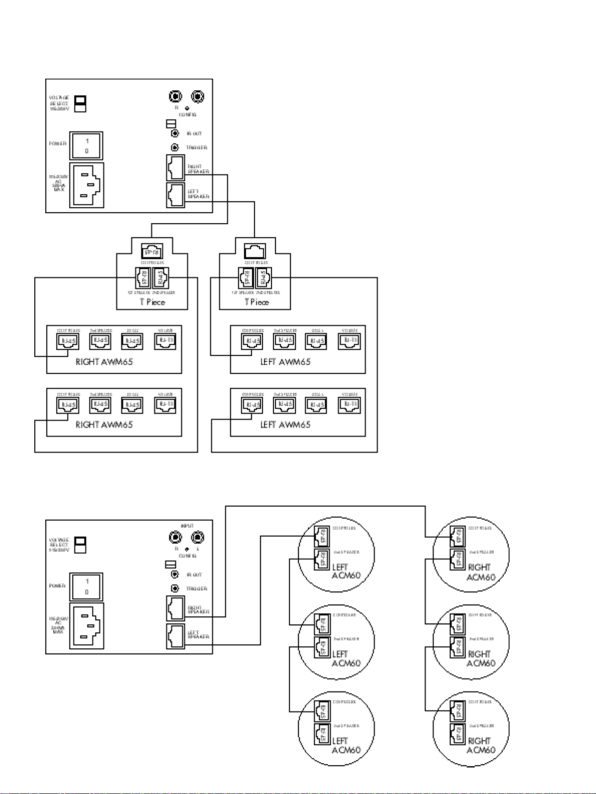
CONNECTIONS FOR ADDING
S P E A K E R S
Additional Speakers
( F i g u re 5 & 6)
Additional speakers can be connected using
RJ-45 T-pieces or to the socket marked
‘2nd Speaker’ on the ACM™60. The total
loading should not be exceeded if simultaneous
maximum volume levels are re q u i red – see
section Loading Considerations.
LOADING CONSIDERAT I O N S
I n t e rface loading is governed by the perm i t t e d
number and type of speakers on any one
i n t e rface. The loading of speakers for one
I n t e rface is as follows:
• 1 pair of AW M ™ 7 0 s
• 2 pairs of AW M ™ 6 5 s
• 5 pairs of ACM™60s
Exceeding this loading will not render an
installation unsafe. The effect will be that
all speakers cannot be played at maximum
power output simultaneously.
C O N N E C T I O N S
( F i g u re 4)
All connections should be made with the
equipment switched off. Connect the audio
s o u rce – such as a preamplifier or surro u n d
sound processor – to the RCA type phono
sockets. Connect the RJ-45 terminated STP
C a t e g o ry 5 speaker cables to the RJ-45 sockets.
I n f r a red remote signals picked up by speakers
connected to the Interface are present at the
mono 3.5mm jack at the rear of the Interf a c e .
This socket is designed to drive third party IR
window emitters with its output of 5V. The
modulation frequency of the IR output signal will
be approximately 38kHz irrespective of the
modulating frequency of the original re m o t e
c o n t ro l .
4
Page 7

C A S A™ IN T E R FA C E
D e s c r i p t i o n
Total output power
Audio inputs
Audio outputs
Power outputs
I n p u t
O u t p u t
D i m e n s i o n s
We i g h t
Two channel power supply for Casa speakers
200W @ +/– 24V
Unbalanced 2VRMS
Balanced, 47ohm sourc e
Maximum draw 100W per output socket,
e l e c t ronic current limit and polyswitch pro t e c t i o n
E x t e rnal trigger capability, selectable sense, 3.5mm jack
IR relay output 38kHz modulation frequency – 3.5mm jack
H e i g h t :
Wi d t h : 105mm (4.25in)
D e p t h : 305mm (12in)
4kg (9lbs)
90mm (3.5in)
B&W Loudspeakers Ltd. reserves the right to amend specifications without notice in line with technical developments. Copyright © B&W Loudspeakers Ltd.
B&W Loudspeakers Ltd, Meadow Road, Wo rthing, BN11 2RX, England Tel: +44 (0) 1903 524801 Fax: +44 (0) 1903 5 2 4 7 2 5 .
B & W L o u d s p e a k e r s o f A m e r i c a , 5 4 C o n c o rd S t re e t , N o rt h R e a d i n g , MA 01864-2699 Tel: (1978) 664 2870 Fax: (1978) 664 4109.
B&W Loudspeakers (Asia) Ltd, Flat U, 11F Camelpaint, Building Block 111, 60 Hoi Yuen Road, Kwun Tong, Kowloon, Hong Kong.
Tel: (8522) 790 8903 Fax: (8522) 341 2777. http://www.bwspeakers.com Printed in England.
 Loading...