

Page 1
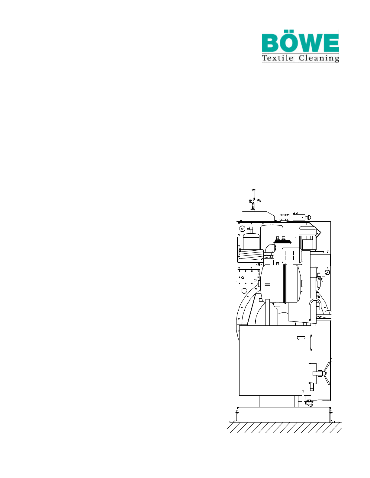
P 240 P 300 USA
P 300 P 350 USA
Installation Instructions
IA. P 240 /P 300 / /09.01 /E IV
SN 703868
IP240e0901
Page 2
This machine, which works with the solvent
tetrachloroethane (perc), complies with the
EC Machinery Directive 98/37 EC,
the EC Low Tension Directive 73/23 EEC
as amended by RL 93/68 EEC, EMV-recommendation
according to EN 55022 and ENV 50140 and the
Harmonised Standards:
EN 292 Part I and Part II
EN 60204-1 (DIN-VDE 0113 Part I)
EN 418
EN ISO 8230*
The contents are correct to the best of our
knowledge and belief and correspond to the
present level of technology. No legal claims
can be derived.
Technical modifications reserved.
Reproduction or duplication only with our
express premission.
* with options: - post separator and
- overfilling sensor still
Page 3

Necessary operation items and chemical additives
Dear customer,
At the time your dry-cleaning machine P 240 (P 300 USA)
P 300 (P 350 USA) will be installed please make sure that the following
items are available:
- Solvent
It is only allowed to use TETRACHLOROETHANE (perc) stabilised, high
purity, according to DIN 53978.
Total filling amount for the first filling: P 240 (P 300 USA): 220 l (360 kg)
P 240 (P 300 USA): 58.1 USgal (794 lb)
P 300 (P 350 USA): 260 l (420 kg)
P 300 (P 350 USA): 68.7 USgal (926 lb)
Tank I: min. filling volume: P 240 (P 300 USA): 60 l (15.9 USgal)
P 300 (P 350 USA): 70 l (18.5 USgal)
- Chemical additives
Chemical additives with thermal stability under operation conditions must be
used.
Depending on the equipment the following should be available:
- cleaning aids
- antistatic agent
- waterproofing
- pre- and post spotting
BÖWE Textile Cleaning GmbH
Rumplerstraße 2, D-86159 Augsburg
Telefon (08 21) 57 07-0, Telefax (08 21) 57 07-351
Phone: ++49-821-5707-0, Fax: ++49-821-5707-351
email: [email protected]
Page 4
1
Dear Customer,
It gives us great pleasure to supply you with
your BÖWE machine.
In designing and building it we have attached
great importance to quality. It is up to the
latest level of research and technology.
Please do not put this installation instructions aside
unread!
These instructions contain important information on
operational details of your drycleaning machine.
If the specified maintenance work is neglected or carried out
inexpertly,repair work is not carried out by service technicians authorized
by BÖWE and no original BÖWE spare parts are used, we cannot meet
the warranty obligations contained in our General Terms of Delivery.
Measurements and other values are as at printing
date.
We reserve the right to make technical changes
without prior notice in the interest of further
development or required constructional
modifications.
Reproduction - including excerpts - is only
permitted with prior written approval and
acknowledgements.
BÖWE Textile Cleaning GmbH
Rumplerstraße 2, D-86159 Augsburg
Telefon (08 21) 57 07-0, Telefax (08 21) 57 07-351
Phone: ++49-821-5707-0, Fax: ++49-821-5707-351
email: [email protected]
P240 IA
Page 5

2
Table of contents
Page
1. General information 4
2. Machine side profile 5
3. Transportation 6
3.1 Entry 7
4. Foundation
4.1 Foundation measurements
Slimline 8
Crossline 9
4.2 Anchoring 10
4.3 Noise or vibration insulation 10
5. Machine fixing
5.1 Machine trough 11
5.2 Anchoring methods 11
5.3 Cemented-in stone bolts 12
5.4 Safety expanding anchors 12
5.5 Threaded rods (bored-through ceiling) 12
5.6 Adhesive plugs /shear connector 13
6. Installation
6.1 Surrounding conditions 14
6.1.1 Regulations 14
6.1.2 Temperature 14
6.1.3 Structural surroundings 14
6.2 Place of installation 15
6.2.1 Required space
Slimline 15
Crossline 16
6.2.2 Machine dimensions 17
6.3 Floor load 17
6.3.1 Dimensions 17
Page 6
3
Table of contents
Page
7. Connection
7.1 Machine dimensions specification
Slimline 18
Crossline 19
7.2 Machine connections specification
Slimline 20
Crossline 21
7.3 Piping 22
7.3.1 Steam 22
7.3.2 Condensate 22
7.3.3 Cooling water supply 23
7.3.3.1 City cooling water connection 23
7.3.3.2 Cooling tower operation 23
7.3.3.3 Other cooling water save devices 24
7.3.4 Cooling water outlet 24
7.3.5 Contact water 24
7.3.6 Compressed air 24
7.3.7 Venting ducts 24
7.3.8 Electric connection 24
7.3.9 Actuation of room ventilation 28
8. Important hints
8.1 First start-up 29
8.1.1 Filling the machine with solvent 29
8.1.2 Replenishing solvent 30
8.2 Refrigeration unit 30
9. Technical data
9.1 P 240 with /without Slimsorba 31
P 300 USA with /without Slimsorba 33
9.2 P 300 with /without Slimsorba 35
P 350 USA with /without Slimsorba 37
10. Setting and optimal operating values 39
11. Safety hints 41
Page 7
4
1. General information
Technical literature
We make reference to the publications and leaflets by the trade and professional
associations as well as research institutes and the safety data sheets of the
solvent producers.
Laws and regulations
All regulations concerning the industry, particularly with regard to proper handling of the
solvent TETRACHLOROETHANE (Perc), have to be met absolutely in order to avoid health risks
and environmental damage.
In any case please observe applicable laws and regulations in your country.
The machine meets the following requirements:
- EC Machinery Directives 98/37 EC
- EC Low Tension Directive 73/23 EEC as amended by RL 93/68 EEC
- EMV-recommendation according to EN 55022 and ENV 50140
Applied harmonised standards:
- EN 292 Part I and Part II
- EN 60204-1 (DIN-VDE 0113 Part 1)
- EN 418
- EN ISO 8230*
Applied German Standards and Regulations:
- VBG 20 - Safety Regulations for Refrigeration Equipment
Heatpumps and Refrigeration Plants
- Pressure Vessel Regulations
- CFC - Halon Prohibition Decree
Please observe the specific rules and regulations of your country.
Repair work
Please consult the BÖWE customer service organisation for all maintenance and
repair work as well as operating safety aspects of this high-quality drycleaning machine.
If required, the BÖWE service organisation will use original spare parts.
Safety
Safety devices may not be bypassed, switched off or otherwise be made
inoperative. In case of repair work or first start up please observe applicable
!
industrial safety rules.
Disposal of still residues and processing water must be carried out according
to the laws and regulations in your country.
*with options: - post separator
- overfilling sensor still
Page 8
5
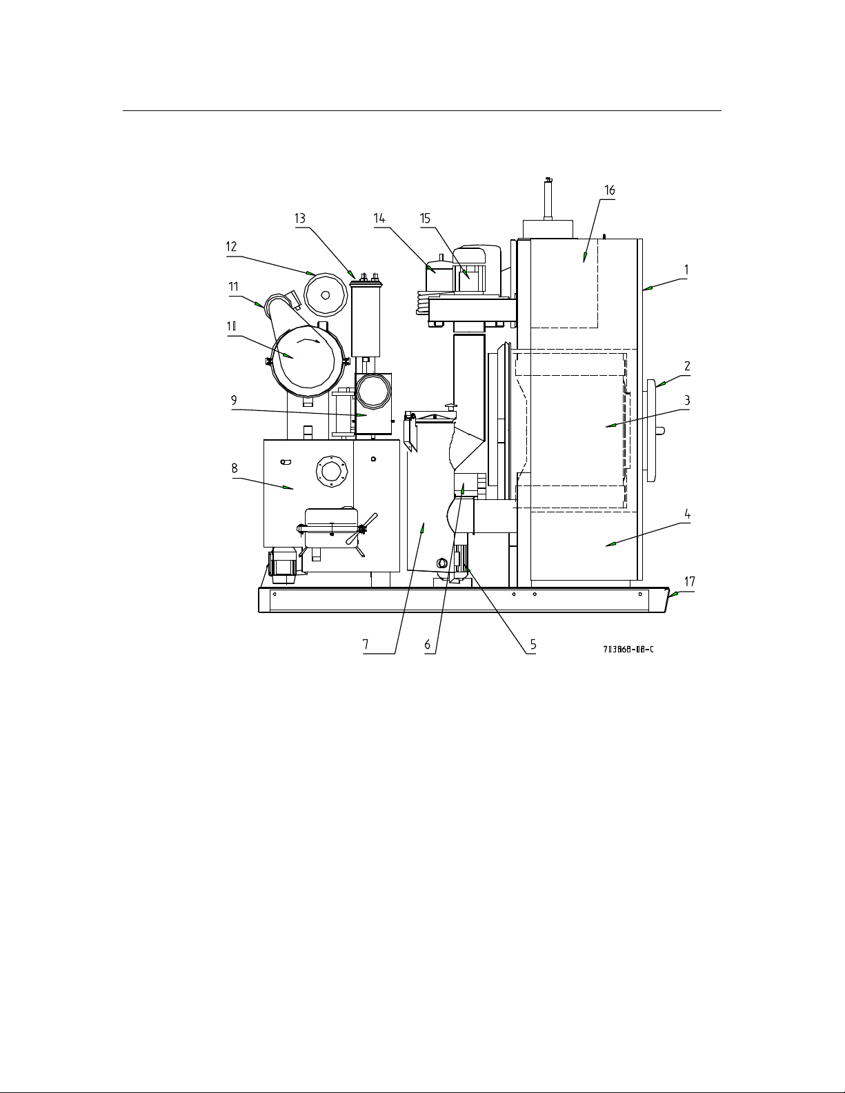
2. Machine side profile
Slimline
1 Control box 10 ECO-filter
2 Loading door 11 Filter drive
3 Cage 12 Adsorption cartridge filter*
4 Tanks 13 Condenser
5 Solvent pump 14 Refrigeration unit
6 Cage drive 15 Fan
7 Lint filter /button trap 16 Recovery section
8 Still 17 Solvent safety trough
9 Water separator
*Option USA-Standard
Page 9
6
3. Transportation
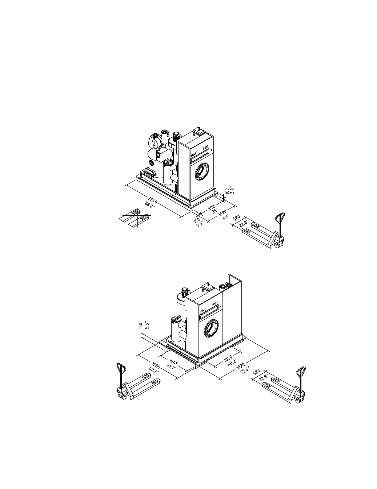
For proper transportation, installation and connection it is recommended to consult
the appropriate experts in order to guarantee a damage-free handling.
For unloading transportation, machine entry and installation it is necessary to use suitable
tools and devices such as a crane, forklift, elevating truck, bottle lift, ropes, winch,
crowbars, rollers, wooden blocks, wedges.
Attention: Pay attention to center of gravity of the machine and secure against lateral tilting.
Slimline
Minimum width of the low lift platform truck 580 mm/22.8 inch!
703868-21-A
Crossline
Minimum width of the low lift platform truck 580 mm/22.8 inch!
703868-22-A
Page 10

7
3. Transportation
3.1 Entry
Normally the machine is transported and entered in upright
position in a wooden crate or box.
Packing dimensions
Slimline Crossline
P 240 /P 300 USA P 240 /P 300 USA
P 300 /P 350 USA P 300 /P 350 USA
_______________________________________________________________________________
Width mm 1150 inch 45.3 mm 1970 inch 77.6
Depth mm 2290 inch 90.2 mm 1640 inch 64.6
Height mm 2250 inch 88.6 mm 2250 inch 88.6
Entry dimensions after unpacking
(Flaphousing and pipework part of cool-down are dismanteled)
_______________________________________________________________________________
Width mm 1080 inch 42.5 mm 1840 inch 72.4
Depth mm - inch - mm 1400 inch 55.1
Height mm 2010 inch 79.1 mm 2010 inch 79.1
Dimensions with dismanteled channel line of the trough
_______________________________________________________________________________
Width mm 955 inch 37.6 mm 1715 inch 67.5
Page 11
8
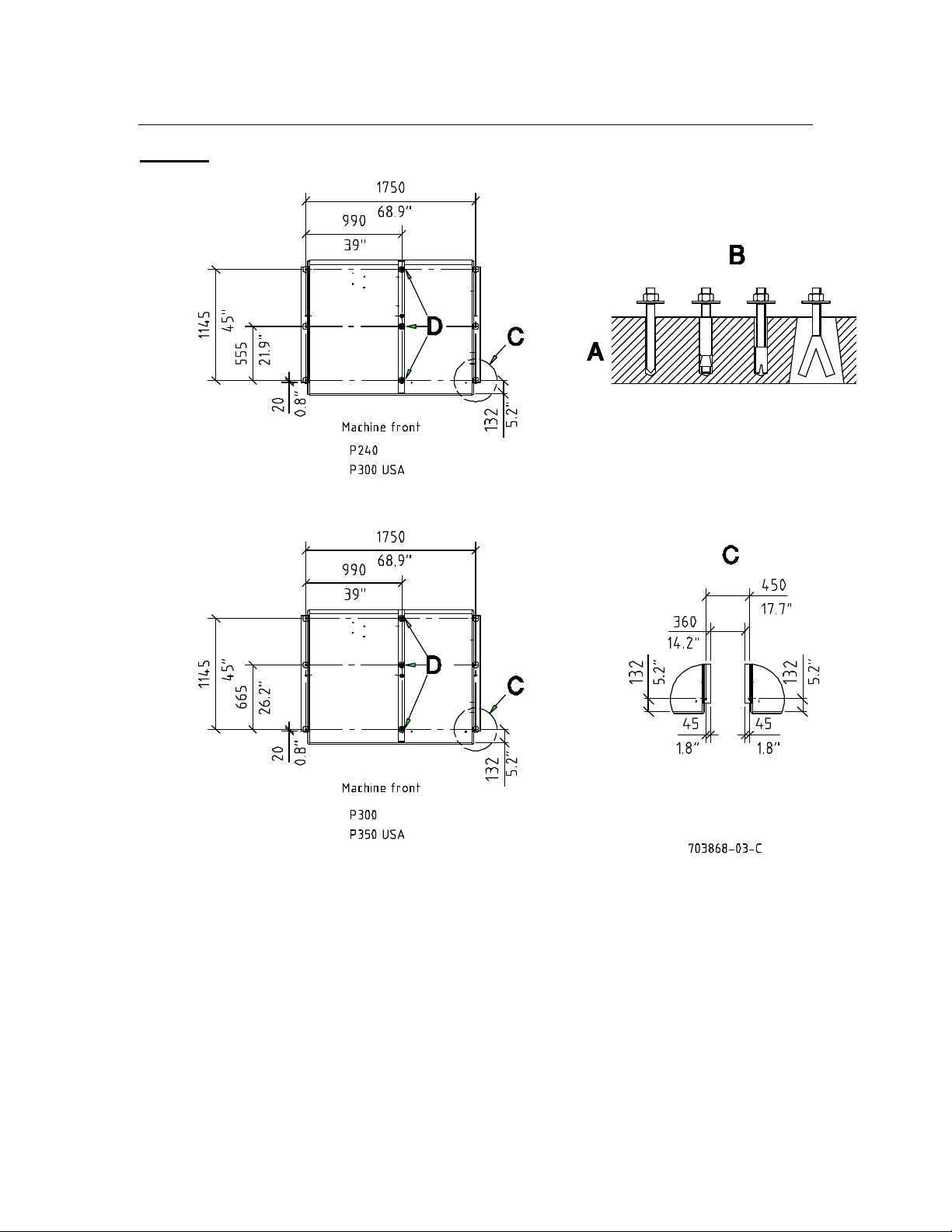
4. Foundation
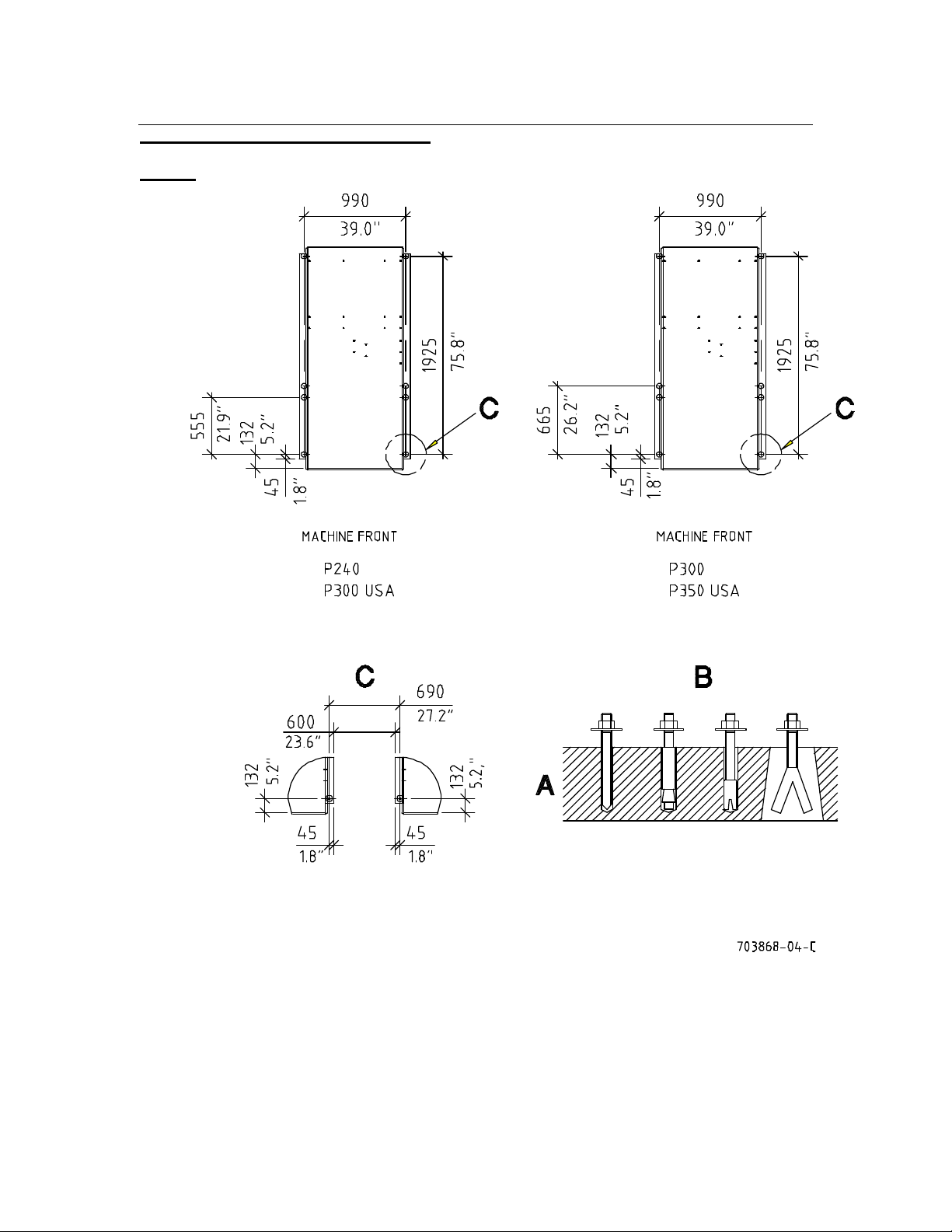
4.1 Foundation measurements
Slimline
A Reinforced concrete: For armoured floors directly on bearing grounds min. 100 mm (3.9 inch)
deep. At rooms with basement an static calculations engineer must be asked.
B Examples for machine fixing
C Distance from machine to next machine
Page 12
9
4. Foundation
Crossline
A Reinforced concrete: For armoured floors directly on bearing grounds min. 100 mm (3.9 inch)
deep. At rooms with basement an static calculations engineer must be asked.
B Examples for machine fixing
C Distance from machine to next machine
D Use foundation anchors M12 x 300
Page 13
10
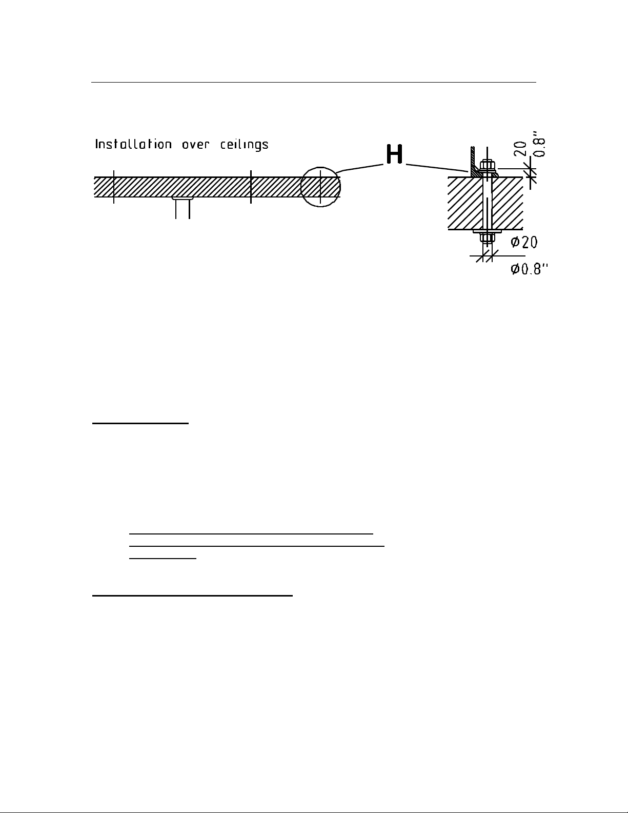
4. Foundation
703871-22-0
Ceiling borehole 20 mm (3/4 inch) ø for through-bolts, length H
depending on thickness of ceiling.
Support if necessary.
4.2 Anchoring
Correct anchoring is very important for low-noise, fault-free
operation. For installation on foundation it is preferable to
use stone bolts!
Seating must be horizontal and level. Do not place machine
directly on tiles, felt, bituminous coatings, rubber or cork.
With uneven concrete floors it is necessary to level the
machine with wedges and fill the spaces with level course
(epoxy resins).
4.3 Noise or vibration insulation
For special vibration insulation special foundations,
dampers etc. can be used in collaboration with building and
insulation specialists.
Page 14
11
5. Machine fixing
5.1 Machine trough
The machine trough is a permanently integrated part of the machine.
Capacity: 245 l / 64.5 US gal Slimline, 290 l / 76.6 US gal Crossline
Material: St1203 /1.0330.03 /3 mm (0.1 inch)
lacquered
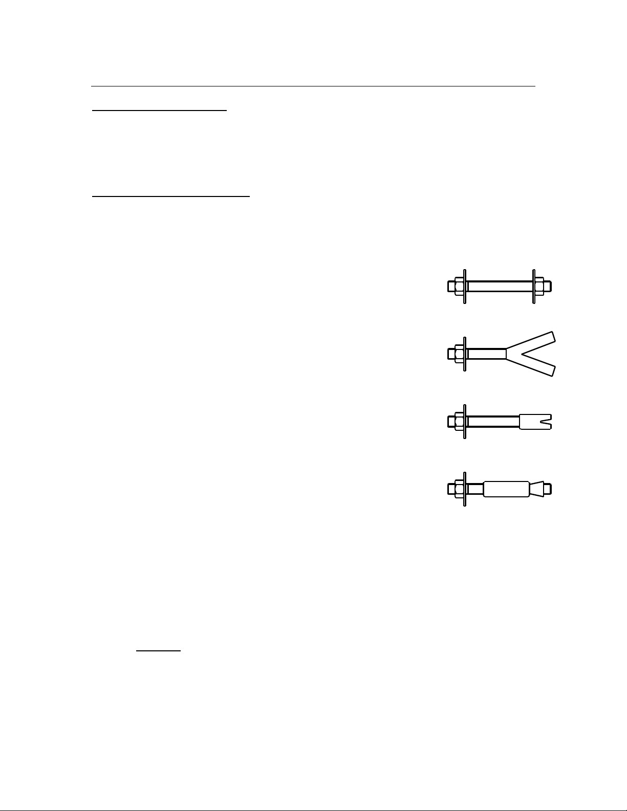
5.2 Anchoring methods
The following anchoring methods can be
alternatively used:
- For installation over ceilings
through bolt (threaded rod)
with washer and nuts M12
- For installation foundation
Stone bolt (length 100 mm/3.9 inch) for cementing in
recessed or morticed holes
(Bolts must not be longer, than the thickness of
the foundation.)
or M12
Heavy-load plugs with threaded rod
in deep bore-holes
or
Safety expanding anchors for inserting
in bore holes
or
adhesive plugs /shear connector. 703871-25-0
Thread for all fixing methods: M 12
Quality: Property class 8.8 - DIN 267
We are not liable for any damage caused by disregarding of our recommendations
and of our information.
Attention
Pay attention to the floor load of the machine floor surface.
The bore holes must be deep enough, to ensure that the plug is
under tension in the conrete.
Page 15

12
5. Machine fixing
5.3 Cemented-in stone bolts
Work sequences:
Insert stone bolts in the holes of the channel lines of the trough with spring washers and nuts.
Level the machine. If the floor is uneven, level machine with wedges and fill
spaces with epoxy resin.
Fill anchoring holes with quick-taking cement.
After kinding tight nuts evenly.
5.4 Safety expanding anchors
Work sequences:
Install machine at intended location.
Use the holes of the channel lines of the trough, as drilling template. Pilot-drill
with stone drill 14 mm(1/2 inch). Minimum drilling depth 100 mm (3.9 inch).
Remove machine or channel lines of the trough. Bore the 18 mm ( 0.7 inch) holes
with the stone drill 18 mm (0.7 inch). Depth 140 mm (5.5 inch).
Remove nuts and washers of the expanding anchors.
Shorten upper plug brush. Put anchors into the drilled holes.
Put the machine on respectively put the channel lines of the trough on and level.
If the floor is uneven, level with wedges and fill spaces with epoxy resing.
Tight anchor nuts evenly.
5.5 Threaded rods (bored-trough ceiling)
Work sequences:
Install machine at intended location.
Use the holes of the channel lines of the trough as drilling template.
Pilot-drill with stone drill 14 mm (1/2 inch).
Remove machine or channel lines of the trough.
Bore the 16 mm (5/8 inch) holes to a diameter of 20 mm (3/4 inch) with the
stone drill 20 mm (3/4 inch) at normal installation over ceiling (see foundation draft).
Put the machine respectively the channel lines of the trough.
The machine must be completely levelled on the ceiling.
If this is not the case, level with wedges and fill spaces with epoxy resin.
Page 16

13
5. Machine fixing
5.6 Adhesive plugs /shear connector
Work sequences:
Install machine at the intended location.
Use the holes of the channel lines of the trough as drilling template.
Pilot-drill with stone drill 14 mm (1/2 inch).
Remove machine or channel lines of the trough.
Bore holes: Bore diameter and depth according to the information of the
plug producer and blow dustfree.
Additional working steps can be taken from the manuals of the producers.
Pay attention to the hardening time.
Put machine respectively channel lines of the trough on and level. If the floor is uneven,
level with wedges and fill spaces with epoxy resin.
Tight nuts evenly.
Page 17
14
6. Installation
6.1 Surrounding conditions
6.1.1 Regulations
Applicable regulations for room ventilation and size, odour
and noise emissions, accident prevention etc. must be met.
The control box contains contacts to control the room air ventilation
(see page 28).
Noise level at a distance of 1 meter (39.3 inch) P 240 /P 300
from the machine and 1.60 m (63 inch) above P 300 USA /P 350 USA
ground (without sound insulation): 64 dB (A)
_________________________________________________________________________
If there is an increase of the airbome sound e.g. by resonance because of space situation
the condition and the distances of the walls and the ceiling etc. it is necessary to take
additional measures of sound insulation.
6.1.2 Temperature
Machine should not be exposed to direct sunlight.
Adequate air supply is to be ensured due to heat exchange
(heat build-up!) Room temperature should not drop below
1 °C (34 °F) owing to the risk of water freezing in the system, and
not exceed 40 °C (104 °F) in continuous operation owing to increased
solvent consumption.
P 240 P 300
P 300 USA P 350 USA
Heat radiation: 9300 kJ 11500 kJ
_________________________________________________________________________
6.1.3 Structural surroundings
Partitions, screens, intermediate ceilings and similar near
the machine are to be fitted in such a way that they do not
hinder operation and are easily and quickly removed for
maintenance and repair.
NOTE!
Do not operate appliances with open flames, e.g. gas-fired
flatwork ironers, tumblers, in the same room, because they
can be damaged by noxious, corrosive gases in the event of
solvent decomposition.
Please ensure that no air from the machine can escape into
a possibly existing heating plant room.
!
Page 18
15
6. Installation
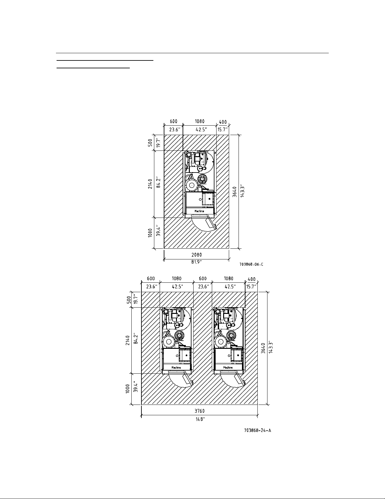
6.2 Place of installation
6.2.1 Required space
Front and rear of the machine should be accessible for
operation, maintenance and repair.
Slimline
Separate installation:
Multiple installation:
Page 19
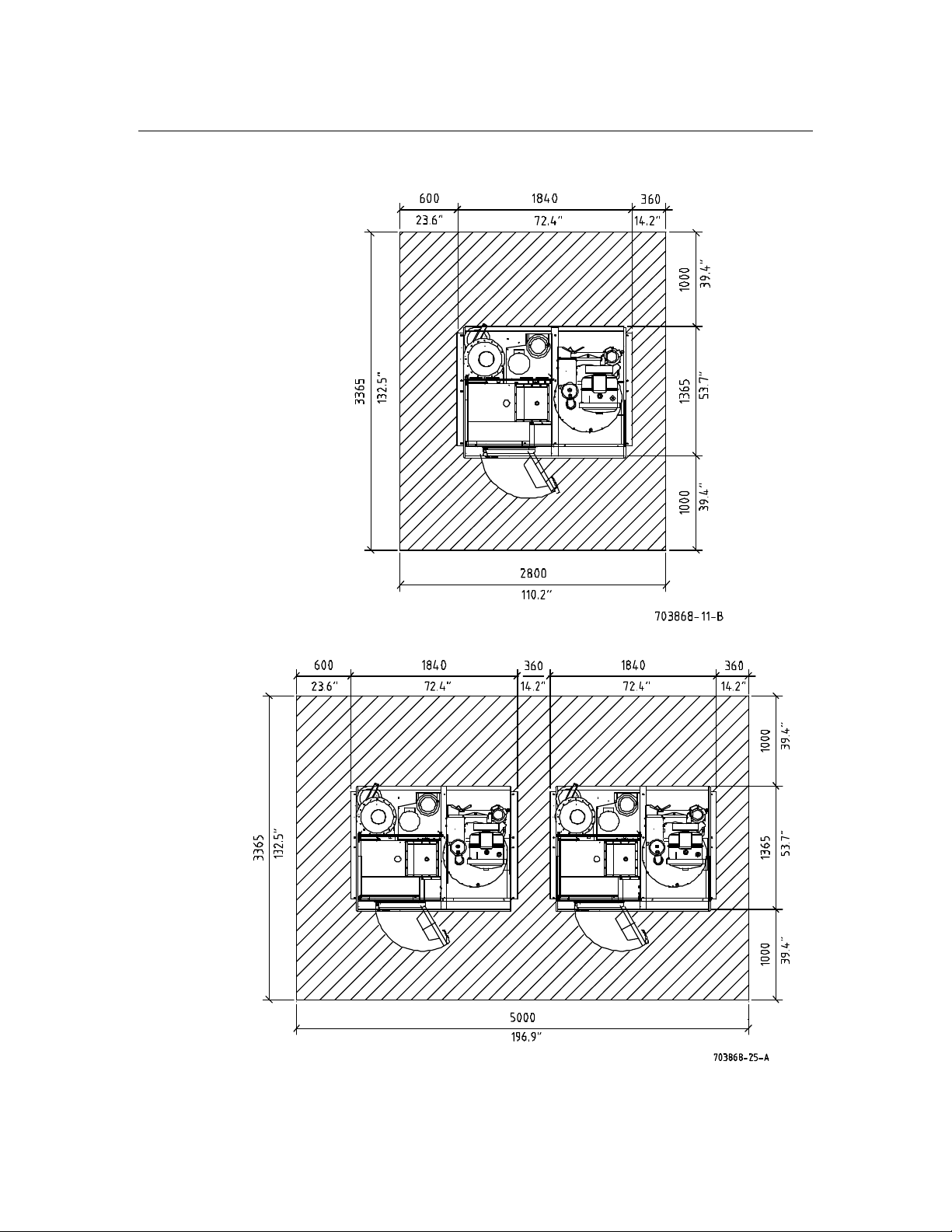
16
6. Installation
Crossline
Separate installation:
Multiple installation:
Page 20

17
6. Installation
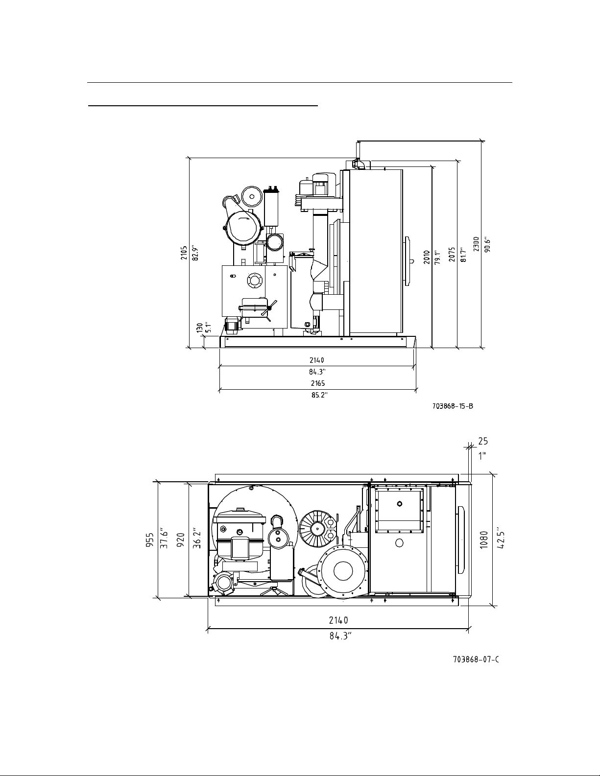
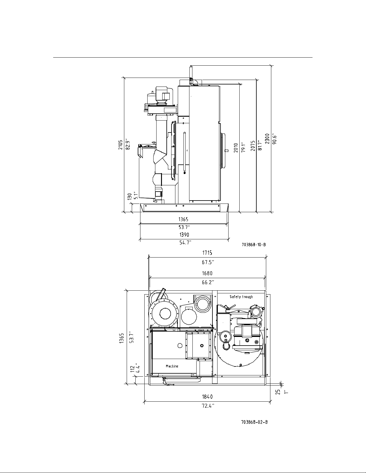
6.2.2 Machine dimensions
Slimline Crossline
P 240 /P 300 P 240 /P 300
P 300 USA /P 350 USA P 300 USA /P 350 USA
_______________________________________________________________________________
Width mm 1080 inch 42.5 mm 1840 inch 72.4
Depth mm 2140 inch 84.2 mm 1365 inch 53.7
Height without cool-down flap mm 2105 inch 82.9 mm 2105 inch 82.9
Height with cool-down flap mm 2300 inch 90.6 mm 2300 inch 90.6
6.3 Floor load
The place of installation must conform to the floor load which is composed of:
- static load = machine weight + max. solvent filling and
- dynamic load = centrifugal cage force with normally
distributed, extraction-damp garments.
The force created during extraction must also be taken into account
(floor, supporting walls etc.). Resonances are not permissible.
Please consult building specialists.
6.3.1 Dimensions
Slimline Crossline
P 240 /P 300 P 240 /P 300
P 300 USA /P 350 USA P 300 USA /P 350 USA
________________________________________________________________________
Depth* mm (inch) 1200 (47.2) 1310 (51.6) 1200 (47.2) 1310 (51.6)
Width* mm (inch) 1080 (42.5) 1080 (42.5) 1080 (42.5) 1080 (42.5)
Portion of the floor surface
for the force transmission m² (sq.ft.) 1.3 (14) 1.41 (15.2) 1.3 (14) 1.41 (15.2)
Weight without solvent kg (lb) 980 (38.6) 1080 (42.5) 1080 (42.5) 1100 (43.3)
Weight with solvent
(stat. load) kg (lb) 1300 (51.2) 1470 (57.9) 1400 (55.1) 1490 (58.7)
Centrifugal cage force
(dyn. load) N 4800 6000 4800 6000
Floor load (stat. + dyn. load)
- Standard drive N/m² 13600 14500 14300 14600
*Portion of the complete machine dimension, that is decisive
for the floor load and the centrifugal cage force.
Regarding the foundation work please consult building experts.
They will take machine-related as well as local particulars into account
and find the best solution.
Please use a load dispatcher frame if the permissible floor load is inadequate.
Page 21
18
7. Connection
7.1 Machine dimensions specification
Slimline
Page 22
19
7. Connection
Crossline
Page 23
20
7. Connection
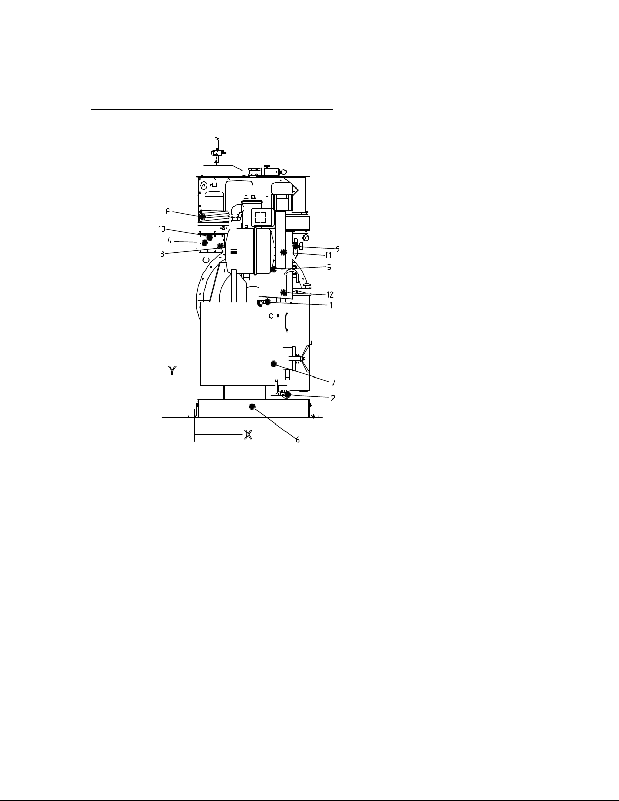
7.2 Machine connections specification
Slimline
703868-16-A
We reserve the right to change measurements!
Pos. Medium NW Zoll - X - - X - - Y - - Y -
mm inch mm inch mm inch
________________________________________________________________________
1 Steam still 15 1/2 610 24 950 37.4
2 Condensate still 15 1/2 775 30.5 190 7.5
3 Condensate heater 15 1/2 220 8.7 1400 55.1
4 Steam heater 15 1/2 90 3.5 1440 56.7
5 Cooling water inlet without tank cooling 15 1/2 660 26 1220 48
6 Cooling water inlet with tank cooling 15 1/2 480 18.9 90 3.5
7 Cooling water inlet still electr.
with water addition 15 1/2 660 26 440 17.3
8 Cooling water outlet 20 3/4 70 2,8 1650 65
9 Compressed air 8 1/4 840 33.1 1400 55.1
10 Electr. connection 130 5.1 1480 58.3
11 Venting water separator 22 - 740 29.1 1360 53.5
12 Rake out system - pump out 20 3/4 740 29.1 1020 40.2
Page 24
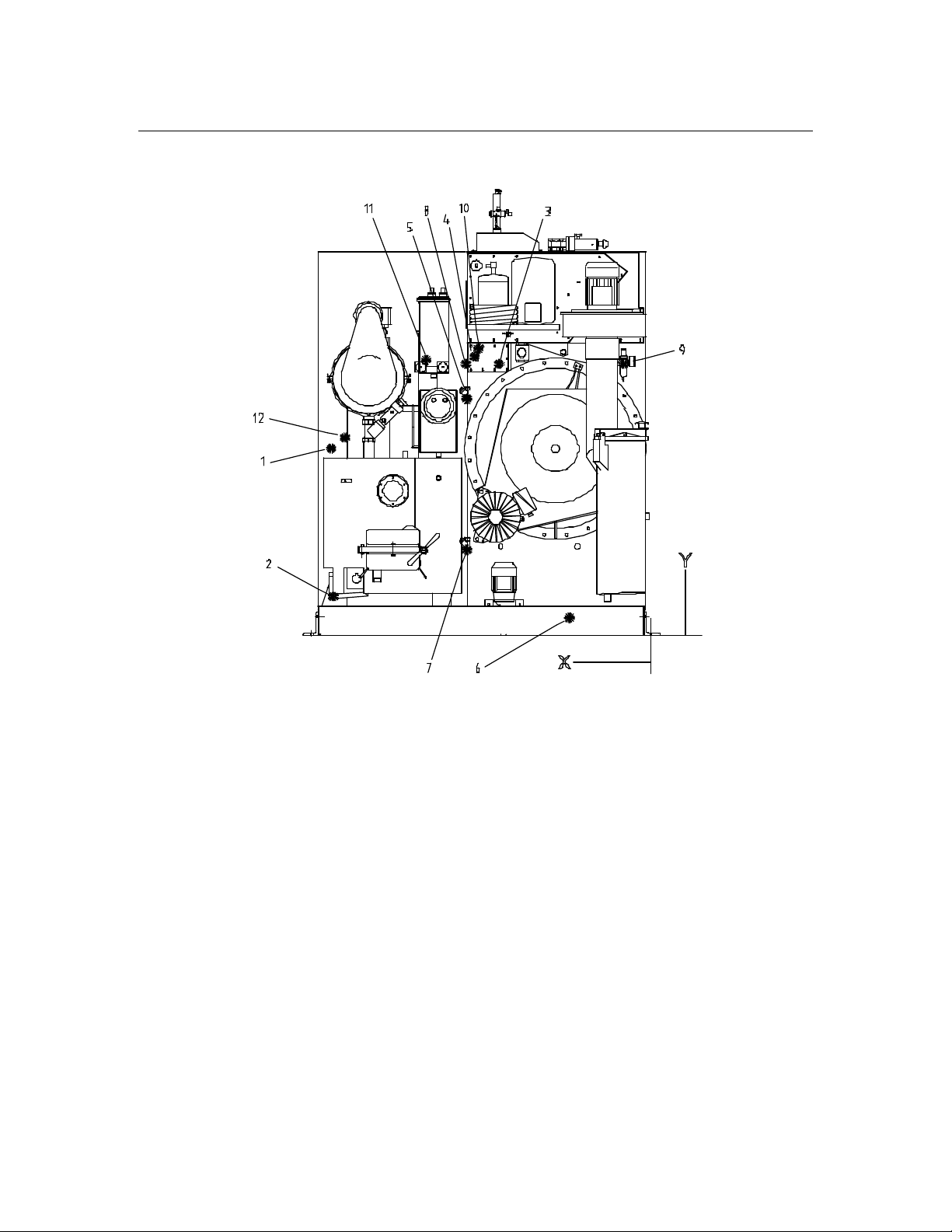
21
7. Connection
Crossline
703868-12-A
We reserve the right to change measurements!
Pos. Medium NW Zoll - X - - X - - Y - - Y -
mm inch mm inch mm inch
________________________________________________________________________
1 Steam still 15 1/2 910 35.8 1440 56.7
2 Condensate still 15 1/2 1640 64.6 190 7.5
3 Condensate heater 15 1/2 785 30.9 1400 55.1
4 Steam heater 15 1/2 1650 65 965 38
5 Cooling water inlet without tank cooling 15 1/2 950 37.4 1220 48
6 Cooling water inlet with tank cooling 15 1/2 420 16.5 90 3.5
7 Cooling water inlet still electr.
with water addition 15 1/2 950 37.4 440 17.3
8 Cooling water outlet 20 3/4 955 37.6 1400 55.1
9 Compressed air 8 1/4 140 5.5 1400 55.1
10 Electr. connection 890 35 1480 58.3
11 Venting water separator 22 - 1160 45.7 1420 55.9
12 Rake out system - pump out 20 3/4 1580 62.2 1020 40.2
Page 25
22
7. Connection
7.3 Piping
Connect the supply and drain pipes (supplied by customer) in accordance with the
installation details. Steam, compressed air and water must be equipped with stop valves.
Water connection must be according to DIN 1988. To avoid sound conduction through
solids, an intermediate piece - made of flexible metal hose - can be connected and the
pipe holders can be insulated.
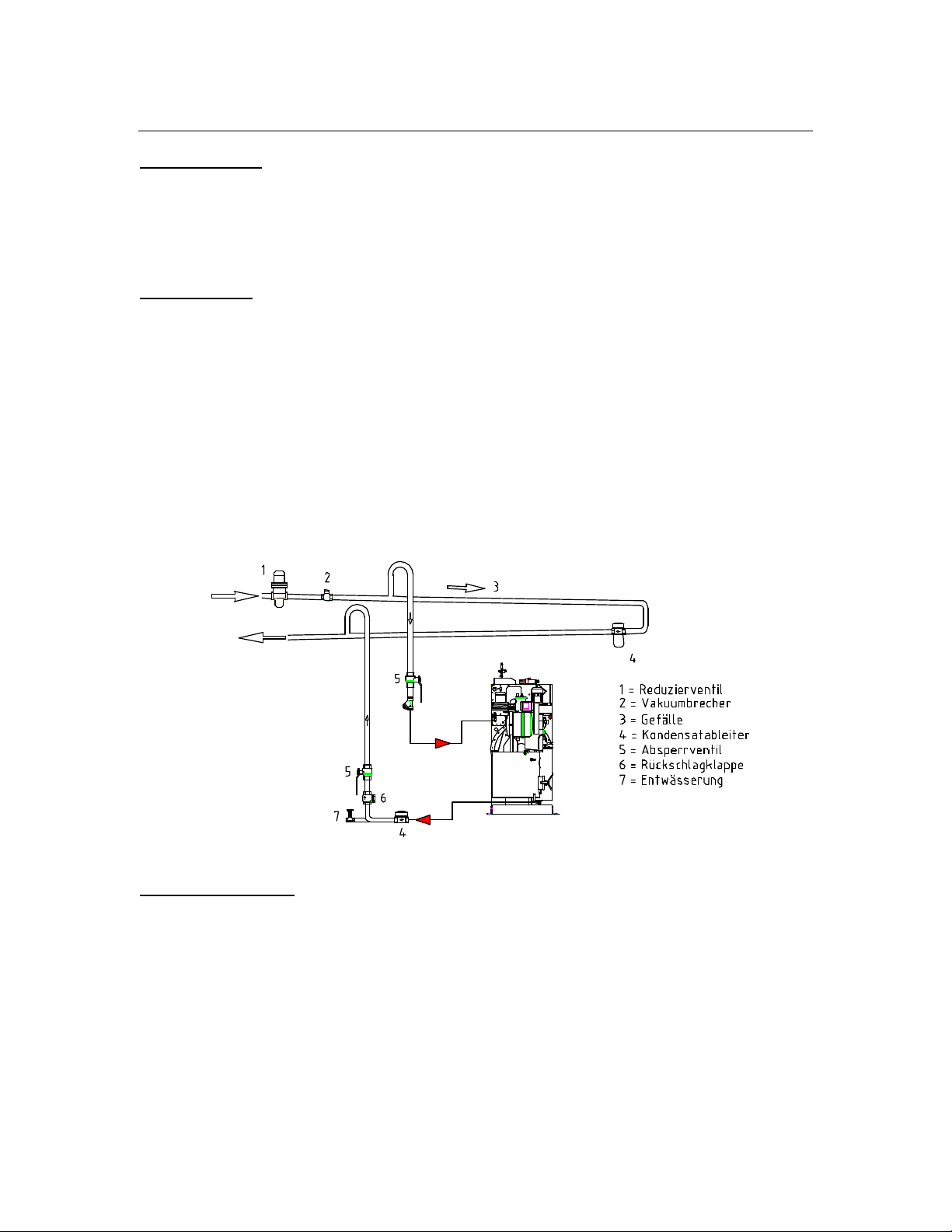
7.3.1 Steam
Insulate the installation and connection pipes. Avoid the use of asbestos!
Operating pressure 4 - 5 bar (58 - 72.5 psi) saturated steam. At a pre-pressure of
more than 5 bar (72.5 psi) a reducing valve with pressure gauge must be installed
and set in a way that the admissible max. perc temperature of 150 °C (302 °F)
(please measure!) is not exceeded. (Danger of solvent decomposition and machine damage!)
Steam peak demand: P 240 /P 300
P 300 USA /P 350 USA
(steam generator size) 0.6 kg/min. 1.3 lb/min.
________________________________________________________________________
703868-17-0
7.3.2 Condensate
Install insulated condensation line with a slope, away from machine.
In case of an ascending slope check valve and drainage must be at the lowest point.
Important: Condensate counter-pressure must be at least
1.5 bar (21.8 psi) below the steam inlet pressure.
Page 26
23
7. Connection
7.3.3 Cooling water supply
7.3.3.1 City cooling water connection
Fit the line to the machine without reduction of cross section and if possible
without bends. The heat balance of the machine is optimally set to 12 °C (53.6 °F)
cooling water inlet temperature and a uniform pressure of 2 - 4 bar (29 - 58 psi).
(Minimum pressure 2,0 bar (29 psi); Maximum pressure 6,0 bar (87 psi).
P 240 P 300
P 300 USA P 350 USA
________________________________________________________________________
Cooling water peak demand
2 - 4 bar /29 - 58 psi (12 °C /53.6 °F). l/min. 7.0 9.0
USgal/min. 1.8 2.4
For safety reasons a water flowback stop and venting device should be installed.
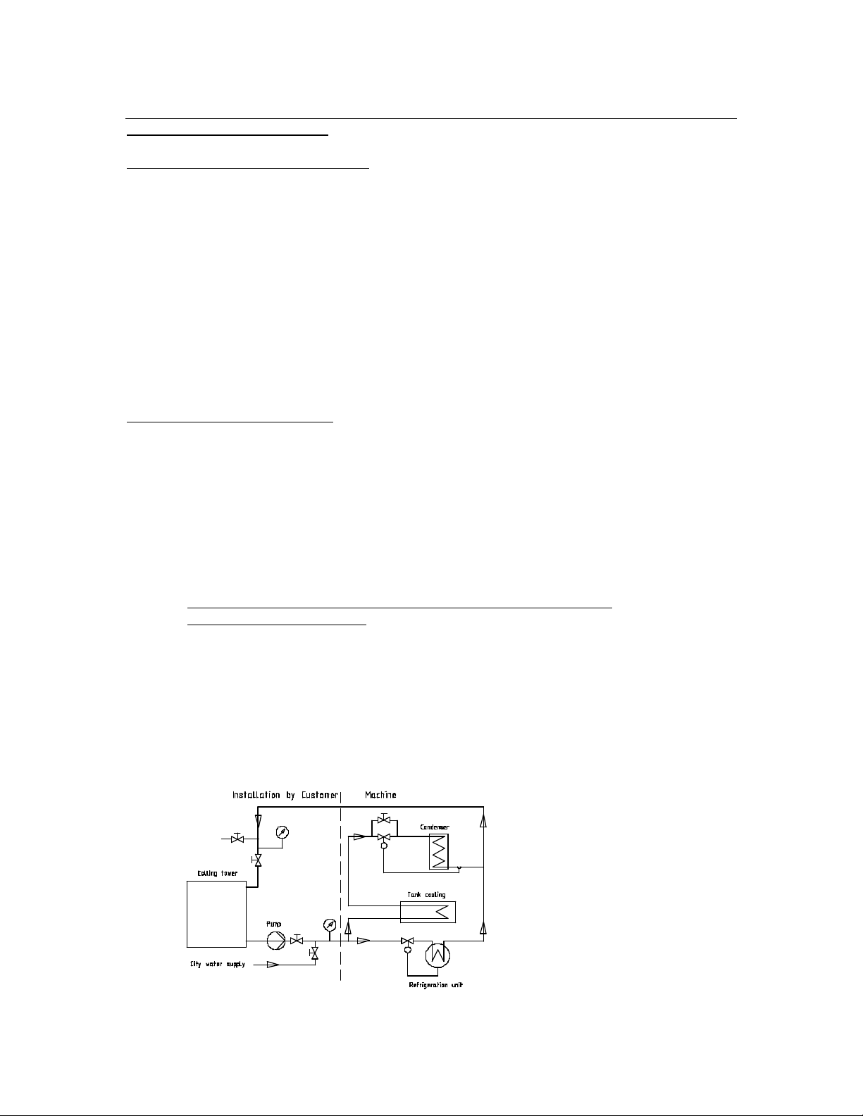
7.3.3.2 Cooling tower operation
We recommend cooling towers from our partner company Geiger D-78224 Singen
for P 240 /P 300 USA: Type WH5-W6
P 300 /P 350 USA: Type WH7-W6
At a cooling tower operation the pipes to and from the machine must be at least
one nominal size larger. Respectively the dimensions must be according to the
nominal size of the pump. Inlet temperatures should not exceed 24 °C (75.2 °F)
as otherwise solvent consumption would increase and the drying time could be longer.
If the temperatures of the cooling water are too high the refrigeration unit may be overloaded.
Water pressure must be adapted to the higher inlet temperature up to
double the max. requirement.
With re-chilling the correct installation is especially important. Among other things,
the following must be taken into account: cooler performance, switch-over to public city
water supply, low temperature storage, pump size, cooling water valve by-pass.
The cooling water regulator for the distillation must be by-passed (continuous water flow).
The cooling water regulator of the refrigeration unit should be exchanged with a regulator
one size larger.
The cooling water supply respectively the feeding of the cooling tower must be from the
city water net or from a soft water system.
703868-26-0
Page 27
24
7. Connection
Data for temperatures up to 24 °C (75.2 °F):
P 240 P 300
P 300 USA P 350 USA
Min. nominal width NW 25/ 1“ 25/1“
______________________________________________________________________
Pump throughput m3/h 1.7 2.2
USgal/h 449.1 581.2
Pump pressure bar 4 - 6 4 - 6
psi 58 - 87 58 - 87
Heat to be eliminated*
without Slimsorba kJ/h 26000 33000
with Slimsorba kJ/h 26500 33500
* refers to water with no additional chemicals
See also the special installation and instruction manual for the re-chiller.
7.3.3.3 Other cooling water save devices
Concerning other possibilities of saving cooling water like cooling water reusing
for wetcleaning- and washing-machines, air-cooled water cooler, refrigeration cooled
water recooling system etc., please contact directly our Sales Support department.
7.3.4 Cooling water outlet
The cooling water from the outlet can be given into the sewage, re-used or recooled,
because in the machine there is a closed circuit and no contact to the solvent.
It should be tried to reuse the water.
7.3.5 Contact water
The contact water collecting container must be drained every day.
Dispose according to the regulations in your country.
7.3.6 Compressed air
Working pressure should be at a minimum 6 bar (87 psi). The machine is equipped with
a compressed air reducing valve, pressure gauge and compressed air water separator
(The network pressure should be 10 - 12 bar /145 - 174 psi).
7.3.7 Venting ducts
The venting ducts of the water separators must lead without diminished cross
section into the open or to the room venting system (if existing).
7.3.8 Electric connection
Pay attention to the supply voltage (machine-plate). Establish connections L1 /L2 /L3,
neutral and protective conductor with corresponding cross-section and fusing.
Pass cable through existing PG union into the control box and connect at terminal.
Connection main switch
The main switch must be connected by customers with an approval cable.
The cable must be dismantled just before the main switch. In the cable channel
in cable must not be dismantled.
Also when the main switch of the machine is turned off, supply voltage has to be
connected to assure function of the crank case heating of the refrigeration unit.
Page 28
25
7. Connection
Fault current in safety switch by customers
We recommend by customers to install a universal sensitive fault current safety switch.
At frequency controlled drive machines you have to install a universal sensitive fault
current safety switch.
P 240 /P 300 USA Operating load max. current Fuse
kW A A
___________________________________________________________________________
400 V, 50 Hz
steam heated 4.5 15.1 20
electrical heated 13.7 27.8 35
steam heated with Slimsorba 5.2 17.3 20
electrical heated with Slimsorba 20.1 38.4 50
230 V, 50 Hz
steam heated 4.3 19.4 25
electrical heated 13.6 41.6 50
steam heated with Slimsorba 5.0 22.9 35
electrical heated with Slimsorba 20.2 59.8 80
230 V, 60 Hz
steam heated 4.3 20.2 25
electrical heated 13.4 41.8 50
steam heated with Slimsorba 4.9 23.7 35
electrical heated with Slimsorba 20.1 59.0 80
200 V, 50 Hz
steam heated 4.9 23.5 35
electrical heated 14.1 49.0 63
steam heated with Slimsorba 5.6 27.2 35
electrical heated with Slimsorba 19.8 66.5 80
Page 29
26
7. Connection
Fault current in safety switch by customers
We recommend by customers to install a universal sensitive fault current safety switch.
At frequency controlled drive machines you have to install a universal sensitive fault
current safety switch.
P 300 /P 350 USA Operating load max. current Fuse
kW A A
________________________________________________________________________
400 V, 50 Hz
steam heated 4.8 15.7 20
electrical heated 13.9 28.1 35
steam heated with Slimsorba 5.5 17.9 20
electrical heated with Slimsorba 20.2 38.6 50
230 V, 50 Hz
steam heated 4.6 22.9 35
electrical heated 13.8 44.8 50
steam heated with Slimsorba 5.3 26.4 35
electrical heated with Slimsorba 20.2 62.4 80
230 V, 60 Hz
steam heated 4.4 20.6 25
electrical heated 13.5 42.1 50
steam heated with Slimsorba 5.0 24.1 35
electrical heated with Slimsorba 20.1 59.4 80
200 V, 50 Hz
steam heated 5.0 23.8 35
electrical heated 14.1 49.0 63
Page 30
27
7. Connection
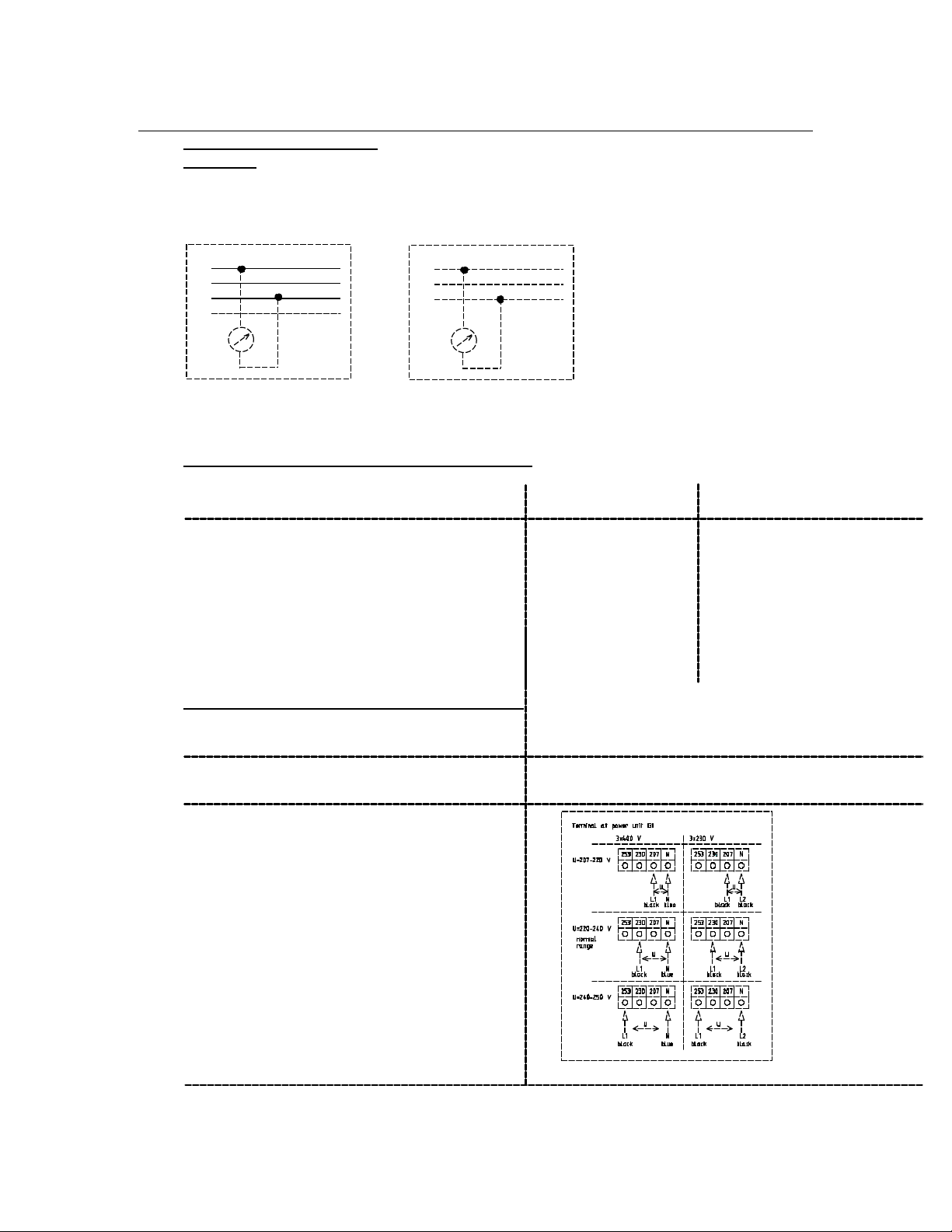
Allowed voltage range
Attention:
Before switching on the machine the power supply at the machine must be measured.
If power supply divates from the international standard, an autotransformer has to be
installed.
3x400V
L1
L2
L3
N
U
At the electrical connection of the dry-cleaning machine the following voltage ranges must be
observed.
1. Main supply (according to DIN IEC 38):
Range primarily 400 V mains primarily 230 V mains
not allowed; external adjustment necessary < 360 V < 207 V
normal range
MIN: - 10,0 % 360 V to 424 V 207 V to 244 V
MAX: + 6,0 %
not allowed; external adjustment necessary > 424 V > 244 V
2. Computer control with power supply:
Range Primarily 230 V - mains
not allowed; external adjustment necessary < 207 V
normal range 207 V - 244 V
703904-18-0
not allowed; external adjustment necessary > 244 V
L1
L2
L3
U
3x230V
Page 31

28
7. Connection
7.3.9 Actuation of room ventilation
If a room ventilation is already installed the machine can be coupled with the ventilation.
Then the machine can only be started if the room ventilation has been switched on.
Recommendation for the renewing of the air in the room
The room ventilation has to meet the requirements of the country regulation.
Example: VBG 66 (Germany)
The minimum amount of air which has to be exchanged in m3/h is:
60 times the maximum load capacity of the drycleaning machine.
The air renewal rate can be limited to 5 times per hour if the above equation gives
a higher amount.
703868-20-0
Page 32
29
!
8. Important hints
8.1 First start-up
First start-up of the machine has to be Attention:
carried out by the BÖWE service organization. Before opening the control
box or removing panelling,
turn main switch to "0".
8.1.1 Filling the machine with solvent
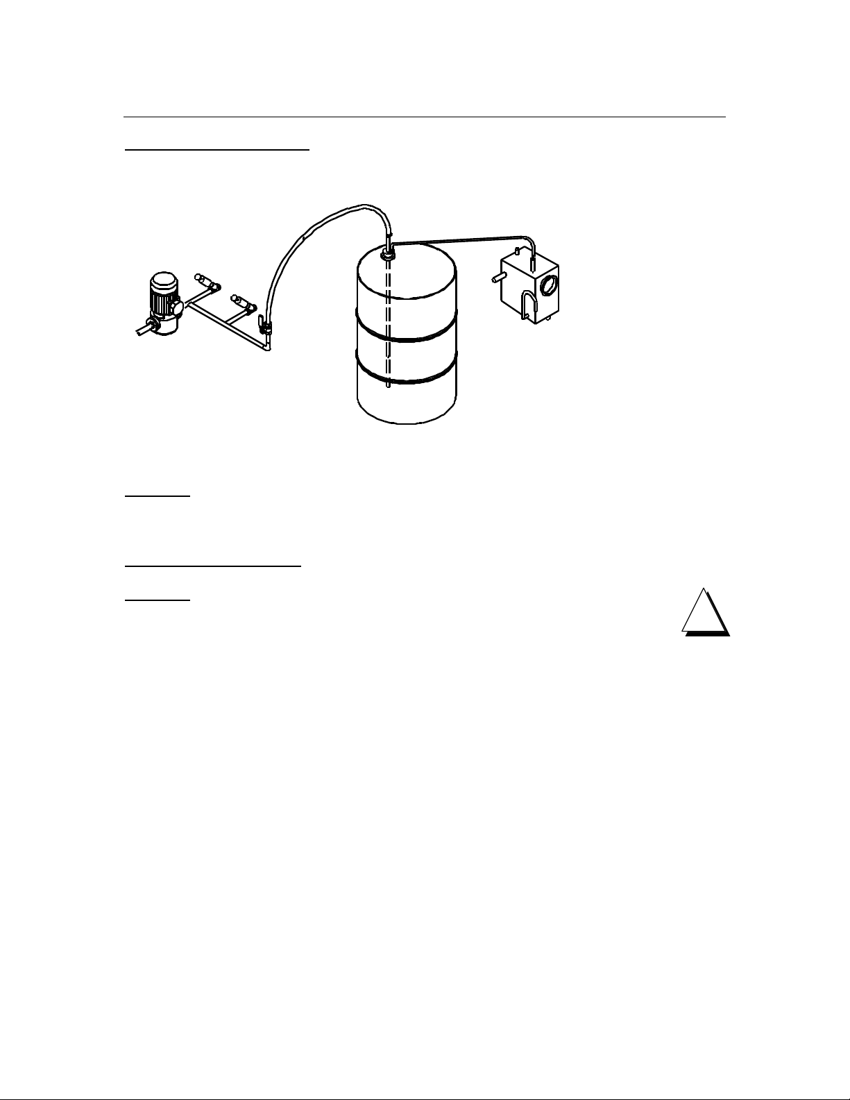
(emission-free filling is standard)
Only use stabilized, neat TETRACHLOROETHANE Attention:
(Perc) in accordance with DIN 53978. Before turning on the
pump must be filled with solvent.
Required solvent amount for the first filling:
P 240 /P 300 USA: 220 l (360 kg) 58.1 USgal (794 lb)
P 300 /P 350 USA: 260 l (420 kg) 68.7 USgal (926 lb)
The emission-free filling takes place in a closed system:
- Screw off pump line cap Attention:
- Connect hose between barrel (bottom) and Perc has a high
pump suction side liposolubility. When using
perc wear gloves and
- Connect hos (gas displacement line) subsequently put on
between barrel and water separator cream on hands. No
smoking. If perc gets
- Open ball valve into the eyes seek further
medical advice.
- Start program P37
- Tanks fill up overflowing one into the other
- Once the tanks are full, stop program P37
- Close ball valve
- Remove hose connection from barrel
- Screw cap back on pump pipe
!
Page 33
30
!
8. Important hints
8.1.2 Replenishing solvent
Use the same procedure as 8.1.1 for replenishing solvent.
703867-04-A
Attention: Empty barrels still contain solvent residues.
For this reason lock barrel tightly and store properly!
8.2 Refrigeration unit
Attention: No cooling agent should escape into the atmosphere from
the refrigeration unit, when work, during maintenance, or when
disposing of the unit.
The amount of refrigeration agent used must be registered
and if desired shown to the competent authorities.
Maintenance work and the disposal of refrigeration units should
only be carried out by persons who have the required experience
and technical equipment.
Page 34

31
9. Technical data
9.1 P 240 with /without Slimsorba
Heating steam electr.
GENERAL DATA:
Filling capacity kg 12 12
Cage volume l 240 240
Cage diameter mm 820 820
Cage depth mm 460 460
Cleaning speed 1/min. 40 40
Extraction speed 1/min. 375 375
max. g-factor 64 64
Low level l 30 30
High level l 60 60
OPERATING LOAD (max. 400 V, 50 Hz)
steam heated kW 4.5 -
electrical heated kW - 13.7
steam heated with Slimsorba kW 5.2 electrical heated with Slimsorba kW - 20.1
CONNECTION CAPACITY:
Compressor capacity kW 3.5 3.5
Fan capacity kW 0.18 /1.1 0.18/1.1
Pump capacity kW 0.55 0.55
Pump capacity still rake out system kW 0.55 0.55
Cage drive capacity kW 0.55 /1.9 0.55/1.9
Filter drive capacity kW 0.37 0.37
Heater capacity kW - 4.3
Still capacity kW - 10
Slimsorba ventilator capacity kW 0.75 0.75
Slimsorba steam generator capacity kW - 6.0
DIMENSIONS:
Machine: Width: Slimline /Crossline mm 1080/1840 1080/1840
Depth Slimline /Crossline mm 2140/1365 2140/1365
Height: without cool-down flap mm 2105 2105
Height: with cool-down flap mm 2300 2300
FILLING VOLUME: Tank I filling l 120 120
Tank II filling l 80 80
Still filling /total l 120/160 120/160
ECO-filter l 40 40
Cartridge filter l 15 15
Page 35

32
9. Technical data
P 240 with /without Slimsorba
Heating steam electr.
CONSUMPTION DATA:
CONSUMPTION PER LOAD*
El. energy total without /with Slimsorba kWh 2.2 /2.4 7.5 /9.3
El. energy drying without /with Slimsorba kWh 2.0 /2.1 3.2 /3.3
El. energy still kWh - 4.3
Saturated steam drying without /with Slimsorba kg 2.0 /2.7 Saturated steam still kg 5.0 Cooling water drying without /with Slimsorba l 45 /60 50 /60
Cooling water still l 65 75
Compressed air (6 bar ) l 6 6
OTHER DATA:
Still throughput (DIN 11916) max. l/h 120 75
Filter throughput l/h 4000 4000
Filter surface ECO-filter m2 2.4 2.4
Weight without solvent Slimline /Crossline kg 980 /1080 980 /1080
Weight with solvent Slimline /Crossline kg 1300 /1400 1300 /1400
Carbon-filling Slimsorba kg 10 10
Floor surface Slimline /Crossline m2 2.3 /2.5 2.3 /2.5
Used floor surface*** Slimline /Crossline m2 1.3 /1.3 1.3 /1.3
Centrifugal cage force N 4800 4800
Floor load (stat. and dyn.) max.
. Slimline /Crossline N/m2 13600 /14300 13600 /14300
Noise level dB(A) 64 64
HEAT BALANCE:
Heat eliminated by cooling water****:
with /without Slimsorba kJ/h 26000 /25000 27000 /26000
Heat radiation to the ambient*:
with /without Slimsorba kJ/h 9500 /9300 9500 /9300
* Values apply to a standard 2-bath-cycle, 1. bath to distillation at cooling water inlet temperature + 12 °C (53.6 °F).
Drum outlet temperature 50 °C (122 °F), condensation pressure 22 bar (319 psi), drying 18 minutes, reduction 6 minutes,
steam supply 4 - 5 bar (58 - 72.5 psi) saturated steam, ambient temperature + 1 to + 40 °C (+ 34 to 104 °F),
with Slimsorba 3 min. reduction, 6 min. adsorption.
*** used part of floor surface for force transmission see point 6.3.1
**** refers to water without any additive
Subject to technical changes!
Page 36

33
9. Technical data
P 300 USA with /without Slimsorba
Heating steam electr.
GENERAL DATA:
Filling capacity lb 26.5 26.5
Cage volume cu.ft. 8.47 8.47
Cage diameter inch 32.3 32.3
Cage depth inch 18.1 18.1
Cleaning speed rpm 40 40
Extraction speed rpm 375 375
max. g-factor 64 64
Low level US gal 7.9 7.9
High level US gal 15.9 15.9
OPERATING LOAD (max. 400 V, 50 Hz)
steam heated kW 4.5 -
electrical heated kW - 13.7
steam heated with Slimsorba kW 5.2 electrical heated with Slimsorba kW - 20.1
CONNECTION CAPACITY:
Compressor capacity kW 3.5 3.5
Fan capacity kW 0.18/1.1 0.18/1.1
Pump capacity kW 0.55 0.55
Pump capacity still rake out system kW 0.55 0.55
Cage drive capacity kW 0.55 /1.9 0.55 /1.9
Filter drive capacity kW 0.37 0.37
Heater capacity kW - 4.3
Still capacity kW - 10
Slimsorba ventilator capacity kW 0.75 0.75
Slimsorba steam generator capacity kW - 6
DIMENSIONS:
Machine: Width: Slimline /Crossline inch 42.5/72.4 42.5/72.4
Depth Slimline /Crossline inch 84.3/53.7 84.3/53.7
Height: without cool-down flap inch 82.9 82.9
Height: with cool-down flap inch 90.6 90.6
FILLING VOLUME: Tank I filling US gal 31.7 31.7
Tank II filling US gal 21.1 21.1
Still filling /total US gal 31.7/42.3 31.7/42.3
ECO-filter US gal 10.6 10.6
Cartridge filter US gal 4.0 4.0
Page 37

34
9. Technical data
P 300 USA with /without Slimsorba
Heating steam electr.
CONSUMPTION DATA:
CONSUMPTION PER LOAD*
El. energy total without /with Slimsorba kWh 2.2/2.4 7.5/9.3
El. energy drying without /with Slimsorba kWh 2.0/2.1 3.2/3.3
El. energy still kWh - 4.3
Saturated steam drying without /with Slimsorba lb 4.4/5.9 Saturated steam still lb 11.0 Cooling water drying without /with Slimsorba US gal 11.9/15.9 13.2/15.9
Cooling water still US gal 17.2 19.8
Compressed air (6 bar) US gal 1.6 1.6
OTHER DATA:
Still throughput (DIN 11916) max. US gal/h 31.7 19.8
Filter throughput US gal /h 1057 1057
Filter surface ECO-filter sq.ft. 25.8 25.8
Weight without solvent Slimline /Crossline lb 2161/2381 2161/2381
Weight with solvent Slimline /Crossline lb 2867/3087 2867/3087
Carbon-filling Slimsorba lb 22.1 22.1
Floor surface Slimline /Crossline sq.ft 24.7/26.9 24.7/26.9
Used floor surface*** Slimline /Crossline sq.ft 14.0/14.0 14.0/14.0
Centrifugal cage force N 4800 4800
Floor load (stat. and dyn.) max.
. Slimline /Crossline N/m
Noise level dB(A) 64 64
HEAT BALANCE:
Heat eliminated by cooling water****:
with /without Slimsorba kJ/h 26000/25000 27000/26000
Heat radiation to the ambient*:
with /without Slimsorba kJ/h 9500/9300 9500/9300
* Values apply to a standard 2-bath-cycle, 1. bath to distillation at cooling water inlet temperature + 12 °C (53.6 °F).
Drum outlet temperature 50 °C (122 °F), condensation pressure 22 bar (319 psi), drying 18 minutes, reduction 6 minutes,
steam supply 4 - 5 bar (58 - 72.5 psi) saturated steam, ambient temperature + 1 to + 40 °C (+ 34 to 104 °F),
with Slimsorba 3 min. reduction, 6 min. adsorption.
*** used part of floor surface for force transmission see point 6.3.1
**** refers to water without any additive
Subject to technical changes!
2
13600/14300 13600/14300
Page 38

35
9. Technical data
9.2 P 300 with /without Slimsorba
Heating steam electr.
GENERAL DATA:
Filling capacity kg 15 15
Cage volume l 300 300
Cage diameter mm 820 820
Cage depth mm 570 570
Cleaning speed 1/min. 40 40
Extraction speed 1/min. 375 375
max. g-factor 64 64
Low level l 35 35
High level l 70 70
OPERATING LOAD (max. 400 V, 50 Hz)
steam heated kW 4.8 -
electrical heated kW - 13.9
steam heated with Slimsorba kW 5.5 electrical heated with Slimsorba kW - 20.2
CONNECTION CAPACITY:
Compressor capacity kW 3.5 3.5
Fan capacity kW 0.18 /1.1 0.18/1.1
Pump capacity kW 0.55 0.55
Pump capacity still rake out system kW 0.55 0.55
Cage drive capacity kW 0.55 /1.9 0.55/1.9
Filter drive capacity kW 0.37 0.37
Heater capacity kW - 5
Still capacity (option**) kW - 10
Slimsorba ventilator capacity kW 0.75 0.75
Slimsorba steam generator capacity kW - 6.0
DIMENSIONS:
Machine: Width: Slimline /Crossline mm 1080/1840 1080/1840
Depth Slimline /Crossline mm 2140/1365 2140/1365
Height: without cool-down flap mm 2105 2105
Height: with cool-down flap mm 2300 2300
FILLING VOLUME: Tank I filling l 145 145
Tank II filling l 95 95
Still filling /total l 120/160 120/160
ECO-filter l 40 40
Cartridge filter l 15 15
Page 39

36
9. Technical data
P 300 with /without Slimsorba
Heating steam electr.
CONSUMPTION DATA:
CONSUMPTION PER LOAD*
El. energy total without /with Slimsorba kWh 2.4 /2.6 8.8/10.6
El. energy drying without /with Slimsorba kWh 2.2 /2.3 3.5 /3.6
El. energy still kWh - 5.3
Saturated steam drying without /with Slimsorba kg 2.8/3.0 Saturated steam still kg 6.5 Cooling water drying without /with Slimsorba l 55 /70 60 /70
Cooling water still l 85 95
Compressed air (6 bar) l 6 6
OTHER DATA:
Still throughput (DIN 11916) max. l/h 120 75
Filter throughput l/h 4000 4000
Filter surface ECO-filter m2 2.4 2.4
Weight without solvent Slimline /Crossline kg 1080 /1100 1080 /1100
Weight with solvent Slimline /Crossline kg 1470 /1490 1470 /1490
Carbon-filling Slimsorba kg 10 10
Floor surface Slimline /Crossline m2 2.3/2.5 2.3/2.5
Used floor surface*** Slimline /Crossline m2 1.41/1.41 1.41 /1.41
Centrifugal cage force N 6000 6000
Floor load (stat. and dyn.) max.
. Slimline /Crossline N/m2 14500 /14600 14500 /14600
Noise level dB(A) 64 64
HEAT BALANCE:
Heat eliminated by cooling water****:
with /without Slimsorba kJ/h 32000 /31000 33500 /32500
Heat radiation to the ambient*:
with /without Slimsorba kJ/h 11700 /11500 11700 /11500
* Values apply to a standard 2-bath-cycle, 1. bath to distillation at cooling water inlet temperature + 12 °C (53.6 °F).
Drum outlet temperature 50 °C (122 °F), condensation pressure 22 bar (319 psi), drying 18 minutes, reduction 6 minutes,
steam supply 4 - 5 bar (58 - 72.5 psi) saturated steam, ambient temperature + 1 to + 40 °C (+ 34 to 104 °F),
with Slimsorba 3 min. reduction, 6 min. adsorption.
*** used part of floor surface for force transmission see point 6.3.1
**** refers to water without any additive
Subject to technical changes!
Page 40

37
9. Technical data
P 350 USA with /without Slimsorba
Heating steam electr.
GENERAL DATA:
Filling capacity lb 33 33
Cage volume cu.ft. 10.59 10.59
Cage diameter inch 32.3 32.3
Cage depth inch 22.4 22.4
Cleaning speed rpm 40 40
Extraction speed rpm 375 375
max. g-factor 64 64
Low level US gal 9.2 9.2
High level US gal 18.5 18.5
OPERATING LOAD (max. 400 V, 50 Hz)
steam heated kW 4.8 -
electrical heated kW - 13.9
steam heated with Slimsorba kW 5.5 electrical heated with Slimsorba kW - 20.2
CONNECTION CAPACITY:
Compressor capacity kW 3.5 3.5
Fan capacity kW 0.18/1.1 0.18/1.1
Pump capacity kW 0.55 0.55
Pump capacity still rake out system kW 0.55 0.55
Cage drive capacity kW 0.55/1.9 0.55/1.9
Filter drive capacity kW 0.37 0.37
Heater capacity kW - 5
Still capacity (option**) kW - 10
Slimsorba ventilator capacity kW 0.75 0.75
Slimsorba steam generator capacity kW - 6
DIMENSIONS:
Machine: Width: Slimline /Crossline inch 42.5/72.4 42.5/72.4
Depth Slimline /Crossline inch 84.3/53.7 84.3/53.7
Height: without cool-down flap inch 82.9 82.9
Height: with cool-down flap inch 90.6 90.6
FILLING VOLUME: Tank I filling US gal 38.3 38.3
Tank II filling US gal 25.1 25.1
Still filling /total US gal 31.7/42.3 31.7/42.3
ECO-filter US gal 10.6 10.6
Cartridge filter US gal 4.0 4.0
Page 41

38
9. Technical data
P 350 USA with /without Slimsorba
Heating steam electr.
CONSUMPTION DATA:
CONSUMPTION PER LOAD*
El. energy total without /with Slimsorba kWh 2.4/2.6 8.8/10.6
El. energy drying without /with Slimsorba kWh 2.2/2.3 3.5/3.6
El. energy still kWh - 5.3
Saturated steam drying without /with Slimsorba lb 6.2/6.6 Saturated steam still lb 14.3 Cooling water drying without /with Slimsorba US gal 14.5/18.5 15.9/18.5
Cooling water still US gal 22.5 25.1
Compressed air (6 bar) US gal 1.6 1.6
OTHER DATA:
Still throughput (DIN 11916) max. US gal /h 31.7 19.8
Filter throughput US gal /h 1057 1057
Filter surface ECO-filter sq.ft.
Weight without solvent Slimline /Crossline lb 2381 /2426 2381 /2426
Weight with solvent Slimline /Crossline lb 3241 /3286 3241 /3286
Carbon-filling Slimsorba lb 22.1 22.1
Floor surface Slimline /Crossline sq.ft
Used floor surface*** Slimline /Crossline sq.ft
Centrifugal cage force N 6000 6000
Floor load (stat. and dyn.) max.
. Slimline /Crossline N/m
Noise level dB(A) 64 64
HEAT BALANCE:
Heat eliminated by cooling water****:
with /without Slimsorba kJ/h 32000 /31000 33500 /32500
Heat radiation to the ambient*:
with /without Slimsorba kJ/h 11700 /11500 11700 /11500
* Values apply to a standard 2-bath-cycle, 1. bath to distillation at cooling water inlet temperature + 12 °C (53.6 °F).
Drum outlet temperature 50 °C (122 °F), condensation pressure 22 bar (319 psi), drying 18 minutes, reduction 6 minutes,
steam supply 4 - 5 bar (58 - 72.5 psi) saturated steam, ambient temperature + 1 to + 40 °C (+ 34 to 104 °F),
with Slimsorba 3 min. reduction, 6 min. adsorption.
*** used part of floor surface for force transmission see point 6.3.1
**** refers to water without any additive
Subject to technical changes!
2
14500/14600 14500 /14600
25.8 25.8
24.7/26.9 24.7/26.9
15.2 /15.2 15.2 /15.2
Page 42

39
10. Setting and optimal operating values
General data: P 240 P 300
Steam pressure (saturated steam) bar 4-5 4-5
Steam temperature (max. permissible) °C 150 150
Cooling water pressure bar 2-4 2-4
Max. cooling water temperature °C 25 25
Compressed air bar 6 6
Cleaning speed 1/min. 40 40
Extraction speed 1/min. 375 375
Reversing cycle sec. 10 -5 - 10 10 - 5 - 10
Low level l 30 35
High level l 60 70
Max. pump pressure bar 2,5 2,5
Filter surface ECO-filter m2 2,4 2,4
Precoat-powder (option only on machines
without emissionfree still rake out system) kg 1,2 1,2
Tank I: min. filling volume l 60 70
Refrigeration technique:
Filling quantity cooling agent R 404A kg 3,5 5,0
Expansion valve Danfoss TES2 °C + 10 to -40 + 10 to -40
Nozzle sizes: Solvent cooling No. 3 3
Drying No. 4 4
High pressure control switch ON bar 22 22
High pressure control switch OFF bar 26 26
Solvent cooling:
Temp.-sensor batch: Solvent cooling ON °C 15 - 30 15 - 30
Drying:
Cooling water regulator:
setting 4 - 6 min. after start drying bar 22 22
Temp.-sensor cage exit: °C 50 50
Temp.-sensor after cooler:
Control temp. drying °C 40 40
Control temp. cycle end °C 15 15
Safety Temp.-sensor heater (only electr.) °C 90 90
Distillation:
Cooling water regulator condenser °C 45 45
Temp.-sensor:
Cycle distillation OFF °C 135 135
Still stripping OFF °C 138/145 (el) 138/145 (el)
Temp.-sensor distilled solvent °C 55 55
Bore diameter in the reduction of the steam piping mm 4 4
Bore diameter in the reduction in direct steam piping mm 3 3
Water filling quantity in heating chamber approx. l 5 5
Still pressure control switch (only electr.)
ON bar 5,2 5,2
OFF bar 5,6 5,6
Attention: No cooling againt should excape into the atmosphere from
the refrigeration unit, when working, during maintenance, or when
disposing of the unit. The amount of refrigeration agent used must
be registered and if desired shown to the competent authorities.
Maintenance work and the disposal of refrigeration units should
only be carried out by persons who have the required experience
and technical equipment.
!
Page 43

40
10. Setting and optimal operating values
General data: P 300 USA P 350 USA
Steam pressure (saturated steam) psi 58-72.5 58-72.5
Steam temperature (max. permissible) °F 302 302
Cooling water pressure psi 29-58 29-58
Max. cooling water temperature °F 77 77
Compressed air psi 87 87
Cleaning speed rpm 40 40
Extraction speed rpm 375 375
Reversing cycle sec. 10 -5 - 10 10 - 5 - 10
Low level US gal 7.9 9.2
High level US gal 15.9 18.5
Max. pump pressure psi 36.3 36.3
Filter surface ECO-filter ft
Precoat-powder (option only on machines
without emissionfree still rake out system) lb 2.6 2.6
Tank I: min. filling volume US gal 15.9 18.5
Refrigeration technique:
Filling quantity cooling agent R 404A lb 7.7 11.0
Expansion valve Danfoss TES2 °F + 50 to -40 + 50 to -40
Nozzle sizes: Solvent cooling No. 3 3
Drying No. 4 4
High pressure control switch ON psi 319 319
High pressure control switch OFF psi 377 377
Solvent cooling:
Temp.-sensor batch: Solvent cooling ON °F 59-86 59-86
Drying:
Cooling water regulator:
setting 4 - 6 min. after start drying psi 319 319
Temp.-sensor cage exit: °F 122 122
Temp.-sensor after cooler:
Control temp. drying °F 104 104
Control temp. cycle end °F 59 59
Safety Temp.-sensor heater (only electr.) °F 194 194
Distillation:
Cooling water regulator condenser °F 113 113
Temp.-sensor:
Cycle distillation OFF °F 275 275
Still stripping OFF °F 280 /293 (el) 280 /293 (el)
Temp.-sensor distilled solvent °F 131 131
Bore diameter in the reduction of the steam piping inch 0.16 0.16
Bore diameter in the reduction in direct steam piping inch 0.12 0.12
Water filling quantity in heating chamber approx. US gal 1.3 1.3
Still pressure control switch (only electr.)
ON psi 75.4 75.4
OFF psi 81.2 81.2
Attention: No cooling againt should excape into the atmosphere from
the refrigeration unit, when working, during maintenance, or when
disposing of the unit. The amount of refrigeration agent used must
be registered and if desired shown to the competent authorities.
Maintenance work and the disposal of refrigeration units should
only be carried out by persons who have the required experience
and technical equipment.
2
25.8 25.8
!
Page 44

41
11. Safety hints
Each person who is in charge of installing, commissioning, operating, servicing or repairing of the
textile drycleaning machine, must have read and understood the instruction and installation manual.
We explicitly refer to the observance of the respective laws and regulations of the countries in
question.
The drycleaning machine was built according to the latest state of engineering and may only be
assembled, installed, operated, served and repaired by persons familiar with the machine and
informed about possible dangers. The relevant safety regulations as well as other safety and
industrial medicine rules shall be strictly obeyed.
Installation and commissioning
When installing the drycleaning machine the installation instructions should be obeyed. A sufficient
room ventilation system must be available. It must be ascertained that the drycleaning machine can
be turned on only, when the ventilation system is in operation.
The machine should not be installed in rooms with danger of explosion or in rooms with gas heated
machines.
The first start-up is carried out by the service department of the BÖWE Organization.
Authorized use
This textile drycleaning machine is exclusively designed for operation with TETRACHLOROETHANE
(Perc). The direct handling with these solvents should be reduced to absolutely necessary work,
whereby safety gloves and -goggles should be worn.
Inflammable, poisonous, or radiactive textiles must not be treated.
It is relevant that the prescribed BÖWE operating, service and maintenance regulations are
maintained.
Unauthorized changes and alterations of the equipment exclude liability of the manufacturer from
resulting damages.
Operation and Maintenance
Operation and maintenance of the BÖWE-textile drycleaning machine is reserved for qualified and
trained specialist staff. Take system into operation only after all safety devices (belt protection cage
drive and filter drive) are installed and in function. During operation and maintenance all safety
regulations shall be obeyed.
Check machine daily for operational safety before turning on (for leakages) and control filling
levels. Dispose of lint, distillation residue and process water according to the operating manual.
Do not carry out any maintenance work while machine is running. Please pay attention to the
recommended quality of solvents, lubricants, and additives!
Page 45

42
11. Safety hints
Repairs
Repairs may only be carried out by skilled workers with tools and protection of labour that is
destined for it. Avoid solvent emissions.
When carrying out repairs and cleaning work always turn off main switch, close the locking valves
of the supply lines (steam, condensate and compressed air) and protect equipment from being
turned on unauthorized. (Sign: Don't turn on - Repair Work!). When work is being done on the
electrical system - always remove the master fuse.
Only use original fuses when exchanging defective ones. Work carried out on pneumatic control
parts has to be done without pressure. Check compressed air indicator for pressure. Repairs on
the refrigerating unit may only be done by a refrigeration engineer.
All spare parts used must comply with the technical standards set by the manufacturer.
Setting machine out of operation and disassembly
Setting machine out of operation and disassembly is reserved only for qualified and trained
specialists, with tools and protection of labour that is destined for it.
- Setting machine out of operation and disassembly solvent must be completely
drained off from the machine including pipes and armatures. Residues which can
produce environmental handicaps must be removed.
- Machine pipes and electric wires for supply or disposal must be separated
from network and must be guard against incompetent turn on.
- Cooling agent from refrigeration unit must be removed by trained people
who have the required experience and technical equipment.
.
Page 46
43
!
11. Safety hints
Safety symbol
This safety symbol is used to mark particularly important matters
relating to safety. It highlights potential hazards and serves to protect
!
Safety instructions
_ No eating, drinking or food storage in the area where the machine is installed.
_ No naked flames in the machine room. No smoking.
_ Steam generators should be installed in such a way that they do not draw in air
charged with solvent.
_ When the machine is started for the first time, the operating personnel should
be trained by a qualified BÖWE representative in how to operate the
machine and should also be made of any potential hazards aware and of how to
operate the machine safely.
_ The owner must only employ trained personnel for loading and unloading the
machine, and skilled and trained personnel for maintenance work.
Unauthorised personnel is not allowed to approach the machine.
_ The daily checks prescribed in the operating instruction manual are minimum
requirements. Any changes which occur at the machine which may affect its
safety should be reported immediately by the operating personnel.
_ The owner is obliged:
- to draw up clear guidelines and allocate responsibilities for operation
and maintenance.
- to ensure that machines are only operated if they are in good
condition.
- to ensure that the area around the machine is tidy, clean and safe by
means of clear instructions and regular inspections.
_ The operator must not operate the machine in any way which may place the
health of the personnel, the environment and the safety of the machine at risk.
_ Notice and warning plates must be affixed to the machine and in the room in
such a way that they are clearly visible. Damaged or missing plates must be
replaced immediately. Safety instructions must be followed at all times.
_ In the event of any kind of danger, the machine must be shut down
immediately by turning it off at the main switch.
personnel from physical injury. All relevant legislation and regulations
must be strictly observed since the notes concerning working safety
are only intended to draw attention to areas of particular danger.
BÖWE textile cleaning machines use TETRACHLOROETHANE (Perc).
This solvent is potentially harmful to health and is slightly toxic in the context to the
Hazardous Substances Ordinance, COSHH regulations, etc.
Page 47
44
11. Safety hints
In the event of a solvent leakage:
- Shut down the machine
- Evacuate all the personnel immediately into the open air
- Remedy the cause of the leak (wearing appropriate breathing
apparatus if necessary)
- Change any clothing soaked with TETRACHLOROETHANE (Perc)
- Request BÖWE service personnel if necessary
The proper handling of TETRACHLOROETHANE (Perc) is an important prerequisite for safety
whilst working with the machine.
The following potential dangers should be noted:
- TETRACHLOROETHANE (Perc) is a very good grease remover, it removes
all natural oils from unprotected skin.
Protection: Wear solvent resistant gloves, apply fatty cream to the
hands.
- Liquid TETRACHLOROETHANE (Perc) irritates the eyes very badly.
Protection: Wear goggles.
- Inhaling TETRACHLOROETHANE (Perc) vapours reduces alcohol tolerance.
Protection: Do not consume alcohol at work or shortly afterwards.
- TETRACHLOROETHANE (Perc) decomposes in the presence of a naked
flame or even hot metal.
Protection: No smoking.
- TETRACHLOROETHANE (Perc) vapours irritate the mucous membranes in
the respiratory passages and eyes.
Protection: Prevent escape of vapours, wear breathing
apparatus when carrying out major maintenance work.
Caution: It is possible to smell TETRACHLOROETHANE (Perc) (odour
threshold) in concentrations as low as 5 ml/m3 of air.
- TETRACHLOROETHANE (Perc) has a similar effect on the central nervous
system like that of an anaesthetic, it may cause unconsciousness and, in very
high concentrations, cause death.
- Special rules and regulations for the room containing the machine are defined
in the operating instruction manual supplied by the manufacturer. This manual
also contains guidelines on all additional safety measures and procedures in
the event of operational faults depending on the local situation as well as
instructions for First Aid.
Page 48

45
11. Safety hints
Gemäß EN ISO 8230 befinden sich an der Maschine
nachfolgende Sicherheitshinweise:
In accordance to EN ISO 8230 the machine is fitted with safety
hints as bellow:
Conforme à EN ISO 8230 les indications de sécurité suivantes se trovent
à la machine:
Kontaktwasser kann geringe Spuren von Lösemittel enthalten.
Vorschriftsmäßig entsorgen!
Contact water may contain small quantities of solvent.
Please dispose according to the regulation in your country!
L’eau de contact peut contenir une petite quantité de solvant.
Evacuer l’eau de contact conformément à la réglementation.
SN 709478
Nadelfänger täglich bzw. bei Bedarf öfter reinigen
(nur bei ausgeschalteter Maschine und nach beendeter Trocknungsphase).
Clean button trap if necessary but at least once a day
(only if machine is switched off and the drying phase has been finished).
Nettoyer le filtre à épingles tous les jours et si nécessaire plus souvent
(seulement hors fonctionnement de la machine et après une opération de
séchage).
SN 709479
Reinigen der Destillation nur bei
- ausgeschalteter Maschine und
- kalter Destillierblase durchführen
Clean still only if
- machine is switched off and
- distillation is cold
Nettoyer le distillateur seulement si:
- La machine est hors de fonctionnement
- Le distillateur est revenu à la température ambiante
SN 709480
Page 49
46
11. Safety hints
Vorsicht!
Heiße Oberflächen
Attention!
Hot surfaces
Attention!
Surface chaude
Zulässige Füllmenge
Max. filling capacity
Capacité admissible
Filter täglich bzw. bei Bedarf öfter reinigen
(nur bei ausgeschalteter Maschine und nach beendeter Trocknungsphase).
Clean lint filter if necessary but at least once a day
(only if machine is switched off and the drying phase has been finished).
Nettoyer le filtre tous les jours et si nécessaire plus souvent
(seulement hors fonctionnement de la machine et après une opération de séchage).
Filter und Wasserabscheider dürfen manuell
nur bei leerer Destillation abgelassen werden.
Filter and water separator must only be drained manually
if the distillation is empty.
La vidange manuelle du filtre à solvant et du séparateur d’eau
est seulement permise quand le distillateur est vide.
P 240 /P 300 USA: P 300 /P 350 USA:
12 kg /30 lb
Zulässige Füllmenge
Max. filling capacity
Capacité admissible
SN 708078
15 kg 35.0 lb
Zulässige Füllmenge
Max. filling capacity
Capacité admissible
SN 708079
SN 708076
SN 708086
SN 709482
SN 709481
Page 50
BÖWE Textile Cleaning GmbH
Rumplerstraße 2, D-86159 Augsburg
Telefon (08 21) 57 07-0, Telefax (08 21) 57 07-351
Phone: ++49-821-5707-0, Fax: ++49-821-5707-351
email: [email protected]
 Loading...