

Page 1
IA M12-M15-M18 01.16 /GB
SN 707767
M12-M15-M18
Page 2
This machine complies with the EC Machinery
Directive 98/37 EC, the EC Low Tension Directive 73/23 EEC
as amended by RL 93/68 EEC, EMV-recommendation
89/336/EWG
and the Harmonised Standards:
EN ISO 12100-1 and 12100-2
EN 60204-1 (DIN-VDE 0113 Part I)
EN 1127-1
The contents are correct to the best of our
knowledge and belief and correspond to the
present level of technology. No legal claims
can be derived.
Technical modifications reserved.
Reproduction or duplication only with our
express permission.
M12-M15-M18
Page 3

Dear Customer,
It gives us great pleasure to present you with your
BÖWE machine. You are acquiring a machine that has
been designed and manufactured to meet the highest
quality standards and that corresponds to the latest
standards in research and technology.
Please do not put these installation instructions away
without reading them!
This manual contains all of the important information
that you need to operate your drycleaning machine.
If the prescribed maintenance work is neglected or
improperly performed, if repair work is carried out by
service technicians other than those authorized by
BÖWE or if parts other than original BÖWE spare parts
are used, we naturally cannot fulfill the guarantee
obligations according to our General Terms of Delivery.
Measurements and other values reflect the status as of
the printing date.
We reserve the right to make technical changes at any
time and without prior notice in the interest of
continuing development or when changes are
considered to be necessary for constructional reasons.
Reproduction - including excerpts - is permitted only
with written permission and when the source of the
information is indicated.
BÖWE Textile Cleaning GmbH
Lochmatt 1A, 77880 Sasbach / Germany
T: +49 (0)7841 - 6002 - 200
F: +49 (0)7841 - 6002 - 230
E-Mail: [email protected]
Internet: www.bowe-germany.de
M12-M15-M18
Page 4

Diese Seite ist bewusst leergelassen
This page intentionally left blank
M12-M15-M18
Page 5

Necessary Operating Materials and Chemical Additives
Dear Customer,
In order to prevent any delays in the commissioning of your M12/M15/M18
drycleaning machine, we ask you to make sure that the following operating materials
and chemical additives are available.
- Solvent
The solvents used must have a flash point that is higher than the temperature stated
on the machine nameplate. The polycyclic aromatic compound content is not allowed
to exceed 0.01% by weight. The solvent must be heat-resistant under operating
conditions.
The solvent flash point must be checked every six months.
We recommend that only fresh solvent should be used in order to avoid contamination
through dirt, foreign substances and smells.
Total filling amount for the first filling: M12: approx. 220 l (58.1 US gal)
M15: approx. 260 l (68.7 US gal)
M18: approx. 300 l (79.2 US gal)
Total filling amount for the first filling M12: approx. 280 l (73.9 US gal)
For the 3-tank model: M15: approx. 330 l (87.1 US gal)
M18: approx. 380 l (100.4 US gal)
Tank I: Minimum filling volume: M12: 60 l (15.8 US gal)
M15: 75 l (19.8 US gal)
M18: 90 l (23.8 US gal)
Tank III:* Minimum filling volume: M12: 60 l (15.8 US gal)
M15: 75 l (19.8 US gal)
M18: 90 l (23.8 US gal)
For machines with 2 economy filters: + 40 l (10.5 US gal)
For machines with 2 economy filters and 1 cartridge filter: + 55 l (14.5 US gal)
- Chemical additives
The chemical additives used must be halogen-free and must have a flash point that is
higher than the temperature stated on the machine nameplate. The polycyclic aromatic
compound content is not allowed to exceed 0.01% by weight. The chemical additives
must be heat-resistant under operating conditions.
Depending on the equipment, the following should be available:
- Drycleaning detergent
- Waterproofing agent
- Pre- and post-spotting agents
M12-M15-M18
Page 6
Caution
Attention !
Important information regarding solvents
When delivered, this machine is released only for the solvent specified on the nameplate.
At the time this manual was printed, the following statements are valid:
It is generally possible to use the following solvents:
Cyclosiloxane (such as GreenEarth) with a flash point > 75°C
Hydrocarbons (such as DF 2000) with a flash point > 60°C
Hydrocarbons (such as Total TDC 3, among others) with a flash point > 55°C
Polyglycolether (such as Rynex) with a flash point > 95°C
Solvon K4 (Kreussler) with a flash point > 60°C
HiGlo (Christeyns) with a flash point > 60°C
Intense (Seitz) with a flash point > 60°C
The use of the solvent perchlorethylene is not permitted!
The following must be observed in this regard:
If you plan to use the machine with a solvent whose data differs from that given on the
machine nameplate, you must first consult with BÖWE and obtain its written authorization.
This will require different software and a different nameplate.
Permission to operate the machine becomes invalid in case of non-compliance.
BÖWE Textile Cleaning GmbH
Lochmatt 1A, 77880 Sasbach / Germany
T: +49 (0)7841 - 6002 - 200
F: +49 (0)7841 - 6002 - 230
E-Mail: [email protected]
Internet: www.bowe-germany.de
M12-M15-M18
Page 7
M12-M15-M18
Contents
1 General Information ........................................................................... 1
1.1 Technical Literature ........................................................................................................................... 1
1.2 Laws, Ordinances, Regulations ........................................................................................................ 1
1.3 Corrective Maintenance Work .......................................................................................................... 1
2 Safety Regulations ............................................................................. 2
2.1 Safe Installation and Commissioning .............................................................................................. 2
2.2 Authorized Use ................................................................................................................................... 2
2.3 Operation and Maintenance .............................................................................................................. 3
2.4 Repair Work ........................................................................................................................................ 4
2.5 Decommissioning and Disassembling ............................................................................................ 5
2.6 Further Safety Regulations ............................................................................................................... 5
3 View of the Machine .......................................................................... 8
4 Transport ............................................................................................ 10
4.1 Entry .................................................................................................................................................. 10
5 Installation .......................................................................................... 12
5.1 Operating Environment ................................................................................................................... 12
5.1.1 Regulations ................................................................................................................................. 12
5.1.2 Temperature ............................................................................................................................... 12
5.1.3 Structural Surroundings .............................................................................................................. 12
5.1.4 Machine Environment ................................................................................................................. 13
5.2 Place of Installation ......................................................................................................................... 14
5.2.1 Space Requirements .................................................................................................................. 14
5.2.2 Machine Dimensions ................................................................................................................... 20
5.3 Floor Load ......................................................................................................................................... 28
5.3.1 Dimensions ................................................................................................................................. 28
5.4 Foundation ........................................................................................................................................ 30
5.4.1 Foundations Dimensions ............................................................................................................ 30
5.4.2 Anchoring Surface ...................................................................................................................... 34
5.4.3 Sound and Vibration Insulation ................................................................................................... 34
6 Fixing the Machine in Place .......................................................... 35
6.1 Machine Trough ............................................................................................................................... 35
6.2 Anchoring Methods ......................................................................................................................... 35
7 Connection ......................................................................................... 38
7.1 Dimensioned Drawing of the Machine Connections .................................................................... 38
7.2 Lines and Pipelines .......................................................................................................................... 40
7.2.1 Steam .......................................................................................................................................... 40
7.2.2 Condensate ................................................................................................................................. 40
7.2.3 Cooling Water Supply ................................................................................................................. 41
7.2.4 Cooling Water Outlet .................................................................................................................. 43
7.2.5 Compressed Air .......................................................................................................................... 43
7.2.6 Process Water ............................................................................................................................ 43
M12-M15-M18
Page 8
M12-M15-M18
Contents
7.2.7 Aeration Lines ............................................................................................................................. 43
7.3 Electrical Connection ...................................................................................................................... 44
7.3.1 Permissible Voltage Range ......................................................................................................... 45
7.3.2 Control of Room Ventilation ........................................................................................................ 46
8 Important Information ..................................................................... 47
8.1 First Startup ...................................................................................................................................... 47
8.1.1 Preparatory Work ........................................................................................................................ 47
8.1.2 Filling Machine With Solvent ....................................................................................................... 47
8.1.3 Refilling Solvent .......................................................................................................................... 48
8.1.4 Vacuum Pump ............................................................................................................................ 49
8.2 Refrigeration Unit ............................................................................................................................. 49
9 Technical Specifications ................................................................ 50
10 Settings and Optimum Operating Values ................................ .. 59
11 Safety Remarks Located on the Machine .................................. 63
M12-M15-M18
Page 9

1
1
1 General Information
1
1.1 Technical Literature
1.1
1.2 Laws, Ordinances, Regulations
1.2
1.3 Corrective Maintenance Work
1.3
We make particular reference here to the literature and leaflets of the trade and professional
associations, research institutes and mutual indemnity associations, as well as safety data sheets
provided by the solvent producers.
To avoid health risks and environmental damage, you must strictly comply with all directives and
regulations pertaining to the industry, particularly with regard to proper handling of solvents.
In any case, you must observe the applicable laws and regulations in the country in
which the machine is installed.
The machine complies with the following regulations:
- EC Machinery Directive 98/37 EC
- EC Low Voltage Directive 73/23 EEC in the version RL 93/68 EEC
- EMC Directive 89/336/EEC
- Pressure Equipment Directive 97/23/EC
- Explosion protection guidelines 94/9EC
Applied harmonized standards:
- EN ISO 12100-1 und 12100-2
- EN 60204-1 (DIN-VDE 0113 Part 1)
- EN 1127-1
Applied national standards and directives:
- BGVD4- Accident Prevention Regulations for Refrigeration Plants, Heat Pumps and Cooling
Equipment)
- CFC and Halon Prohibition Ordinance
When operating the system in Germany, the following laws and directives must be observed:
- BG-Regel “Betreiben von Chemischreinigungen” (BGR 500 chapter 2.14)
- Water Resources Law (WHG § 19)
- Waste Disposal Law
- VDI guidelines
- VDE regulations
- 31st BImSchV
- GefStoffV with technical rules (Regulation for hazardous material)
- Operating safety regulation
We recommend that you commission the customer service department of the BÖWE
organization for the maintenance, servicing and operating safety of this valuable
drycleaning machine. They use original BÖWE spare parts.
M12-M15-M18
Page 10
2
2
2 Safety Regulations
2
2.1 Safe Installation and Commissioning
2.1
2.2 Authorized Use
2.2
Each person who is charged with the installation, commissioning, operation, maintenance or repair
of the drycleaning machine must first have read and understood the operating and installation
instructions. In particular, we refer to the observation of the relevant laws and regulations for the
countries in question.
The cleaning machine has been built according to the latest state of the technology. Only persons
who are familiar with the machine and informed of the possible risks are authorized to set up,
install, commission, operate, maintain and repair this machine. The relevant accident prevention
regulations and other regulations involving safety and medical care for workers must be strictly
adhered to.
Safety Symbols
This safety symbol identifies particular information regarding occupational
safety. It points out hazards and serves to protect personnel from physical
injury. You must observe all applicable laws and regulations; the information
on occupational safety only emphasizes particularly dangerous areas. Failure
to observe this information can result in serious consequences for the health,
up to and including life-threatening injuries.
This symbol provides important information on the correct use of the machine.
Failure to observe this information can lead to disturbances in the machine or
surrounding area.
You are not permitted to bypass or turn off safety devices or to make them otherwise inoperative.
You must observe all applicable industrial safety regulations during installation and repair work. You
must dispose of distillation residues and process water in accordance with regulations.
You must install the drycleaning machine according to the enclosed installation instructions.
The room must be sufficiently ventilated.
You are not permitted to operate the machine in potentially explosive areas or in areas in which
systems with open flames have been installed. All electrical systems within a radius of 2 m
(approximately 6.5 feet) must comply with the IP 54 degree of protection.
The BÖWE Organization Customer Service department is responsible for carrying out
the first startup.
This drycleaning machine is designed exclusively for operation with solvents with flash points higher
than the temperature information on the machine nameplate. (See "Necessary Operating Materials
and Chemical Additives"). Handle these solvents directly only when absolutely necessary and wear
protective gloves and goggles.
M12-M15-M18
Page 11

3
3
2.3 Operation and Maintenance
2.3
2 Safety Regulations 2
This closed-circuit drycleaning machine for industrial use (including use in cleaning shops) is
intended for cleaning textile articles (also leather or fur or for treating skins). This drycleaning
machine is not intended for customer access (such as in self-service shops).
You are not permitted to treat textiles that are easily inflammable or poisonous or that contain
radioactive materials.
The definition of authorized use includes compliance with the operating, maintenance and repair
conditions prescribed by BÖWE.
The manufacturer is not liable for damages resulting from unauthorized use or from changes to
the system made without proper authority.
The machines M12, M15, and M18 are not intended for use in a potentially explosive area!
A classification by zones according to the explosion protection guidelines outside the
machine is not necessary!
Inside the machine and the still, only the still is categorized as zone 2!
Only trained service personnel who are familiar with the machine are authorized to operate and
maintain the BÖWE drycleaning machine. Safety regulations must be observed during operation
and maintenance.
Do not start the system unless all protective devices (belt guard for cage and filter drive) are in
place and working.
Check the operating safety of the machine (sealing test) and the liquid levels daily before turning it
on. Dispose of lint, process water and distillation residues according to the operating instructions.
Do not perform any maintenance work when the machine is in operation. Make sure that the
solvents, lubricants and chemical additives meet the specified quality requirements.
Perform maintenance work only when the machine is turned off and secured and has
cooled off.
When the machine is not in operation cooling water feed must be cut off by means of a
stop valve to be fitted on site.
M12-M15-M18
Page 12
4
4
Attention: Drain distillation residues only when the green lamp on the
still is lit.
The collecting tank must hold the amount that is expected to
be drained and must be temperature and solvent-resistant at
up to 150 °C (302 °F)
Attention: Check the liquid level before opening the still door
Attention: Do not allow distillation residues to reach the sewer system
or garbage. You must dispose of these residues according to
country-specific regulations on special waste.
According to the legal stipulations of the German accident prevention
regulations (BGR 500 chapter 2.14), special knowledge is required for the
operation and maintenance of drycleaning systems. A person with this
special knowledge must regularly be present during the operation of
drycleaning systems.
2.4 Repair Work
2.4
2 Safety Regulations 2
Requirements for the owner and operating personnel
As a person / body who runs a plant one is obliged to have the refrigerating plant of
the dry cleaning machine inspected annually with regard to tightness.
Only skilled workers with suitable protection devices and work tools are authorized to carry out
repairs. Make sure that there are no solvent emissions.
During repair and cleaning work:
Turn main switch off
Close the stop valves on the supply lines (steam, condensate and compressed air).
Make sure that the system cannot be turned on without permission (close off and put
up a sign "DO NOT TURN ON - REPAIR WORK “ )
Always remove the main fuse when working on the electrical system.
Use only original fuses to replace defective ones.
When working on pneumatic control parts, make sure that there is no pressure in the system.
Only specially trained refrigeration technicians are authorized to make repairs to the
refrigeration unit.
All spare parts used must comply with the technical standards set by the manufacturer.
M12-M15-M18
Page 13
5
5
2.5 Decommissioning and Disassembling
2.5
Only skilled workers with suitable protection devices and work tools are
authorized to decommission and disassemble the system.
When decommissioning and disassembling the machine, drain all solvent
from the machine, including the pipelines, valves and fittings. You must
remove residues that could cause environmental pollution.
You must separate electric lines and pipelines that were used to supply or
drain the machine from the supply network. Make sure that they cannot
be turned on by unauthorized persons.
2.6 Further Safety Regulations
2.6
This BÖWE drycleaning machine works with a solvent. These solvents
are harmful to the health in the context of the Hazardous Substances
Ordinance.
2 Safety Regulations 2
Have an authorized customer service technician dispose of the cooling agent from the refrigeration
unit.
Drinking, eating and food storage are prohibited in the area where the machine is installed.
Open flames and fires are not allowed in the operating area. No smoking is allowed.
Install steam generators in such a way that they do not draw in air that contains solvent.
A BÖWE customer service representative must train the personnel in the operation of the
machine before the first startup. This training must include information on safe operation
and possible hazards.
The owner is responsible for employing trained personnel to load and unload the machine
and must employ well-informed and expert personnel for maintenance work. No unauthorized
personnel are allowed in the area of the machine.
The daily checks prescribed in the operating instructions represent the minimum requirements.
Operating personnel must immediately report any changes in the machine that could
affect the safety.
M12-M15-M18
Page 14
6
6
2 Safety Regulations 2
The owner is obligated:
- to draw up clear regulations regarding responsibility for operation and maintenance, to ensure
that the machine is only operated when it is in perfect condition and to ensure the order, safety
and cleanliness at the workplace by means of instructions and inspections.
The owner is obligated to make sure that no working method is used that could place the health
of the personnel, the environment or the safety of the machine at risk.
Notice and warning signs must be placed on the machine or in the operating area in plain sight.
Damaged or missing signs must be replaced immediately. The specified safety regulations must be
followed at all times.
In the event of any kind of hazard, stop the machine immediately and turn off the main switch.
If there is a solvent leak:
Turn off the machine
Immediately send all personnel into the open air
Open windows and doors
Cut off the cause of the solvent leak
Change any clothing that is wet with solvent
If necessary, request a BÖWE customer service technician.
The escape of larger amounts of solvent is a reportable malfunction. It must be reported to the
responsible authorities, industrial control group, fire department, water resources board or
subordinate water authorities.
M12-M15-M18
Page 15
7
7
2 Safety Regulations 2
The proper handling of solvent is an important prerequisite for workplace safety.
Note the following potential hazards:
Solvents are very good grease removers; they also remove natural oils from unprotected skin.
Protection: Wear solvent-resistant protective gloves; apply skin cream with oil to the hands.
Liquid solvents are strongly irritating to the eyes.
Protection: Wear protective goggles.
Solvents are combustible.
Protection: Avoid ignition sources (smoking, sparks, fire).
Risk of explosion if the flash point is lowered.
Protection: You must use solvents that have a flash point that is higher than the temperature
stated on the machine nameplate. Use only chemical additives that do not lower the flash
point.
Ignition sources
Protection: Check pockets for cigarette lighters, matches and metallic objects.
Do not overload the machine!
You must hang up any operating instructions from the Clothing Mutual Indemnity Association in a
visible location.
M12-M15-M18
Page 16
8
8
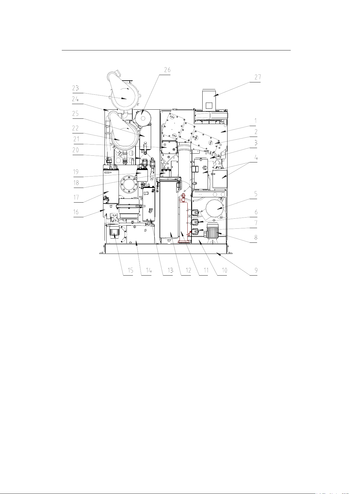
3 View of the Machine
3
1
Airshaft
16
Still
2
Cooling register
17
Extraction tank
3
Cage housing with cage
18
Solvent cooling system
4
Refrigeration unit
19
Flash tank
5
Cage drive
20
Vacuum pump
6
Dosing unit
21
Heater battery
7
Sprayer *
22
Economy filter 1
8
Solvent pump
23
Economy filter 2 *
9
Safety trough
24
Filter drive
10
Tanks 1, 2
25
Condenser
11
Electric steam generator *
26
Adsorption cartridge filter 1*
12
Button trap with lint filter
27
Fan
13
Water separator
14
Tank 3
15
Pump for still rake out system
Crossline
707767-02-A
* Option
M12-M15-M18
Page 17
9
9
1 2
4
7
C
8
0
5
3
BÖWE
E
9
6
START
PROG
HOLDHOLD
START
STOP
PROG
STOP
Wartungs- und Hilfsprogramme
BÖWE
Reinigungsprogramme
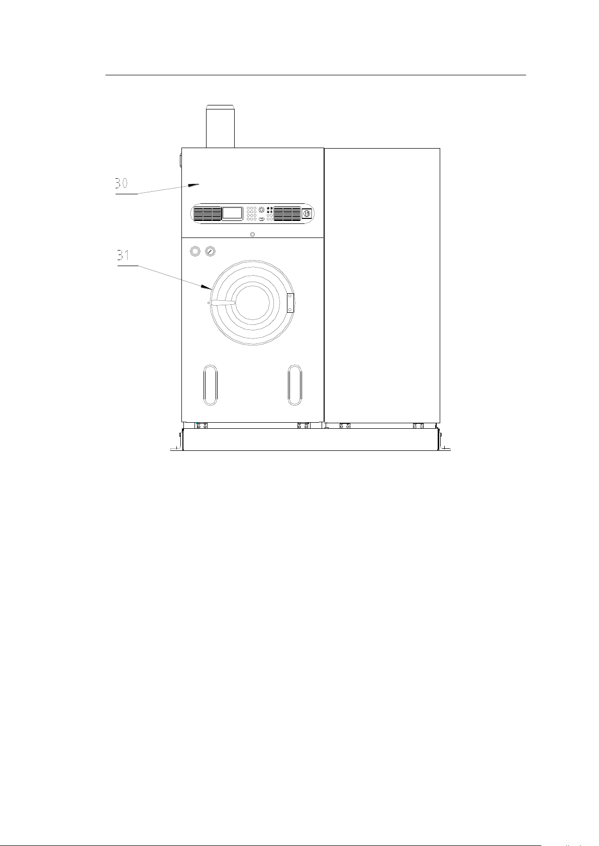
30
Switch box panel
31
Loading door
3 View of the Machine 3
Crossline
707767-01-A
M12-M15-M18
Page 18
10
10
4 Transport
4
Caution
Attention: Note the center of gravity of the machine and secure against
lateral tipping.
4.1 Entry
4.1
Package dimensions (box measurements)
M12/M15/M18
Slimline
Crossline
Width
mm(in)
1150(45.3)
1970(77.6)
Depth M12-M15 /M18
mm(in)
2290(90.2) /2400(94.5)
1640(64.6) /1750(68.8)
Height
mm(in)
2410(94.9)
2460(96.8)
Entry dimensions after unpacking (without pallet, fan is dismantled)
Width
mm(in)
1080(42.5)
1840(72.4)
Depth M12-M15 /M18
mm(in)
2165(85.2) /2275(89.5)
1406(55.3) /1540(60.6)
Height
mm(in)
1995(78.5)
1995(78.5)
Entry dimension without angle bracket for trough
Width
mm(in)
935(36.8)
1695(66.7)
In order to guarantee that no damages result from the handling, we recommend that you
consult with the appropriate experts for correct transport, installation and connection.
You must provide suitable tools and equipment for unloading, transporting, machine entry
and installation. For example: crane, forklift, elevating truck, pulley block, rope, winch, crowbar,
rollers, wooden block, wedges.
Normally the machine is packed in a crate or shipping box and kept in an upright position
when being transported and brought in.
M12-M15-M18
Page 19

11
4 Transport 4
Package dimensions (box measurements)
M12/M15/M18 on Softpad
Slimline
Width
mm(in)
1650(64.9)
Depth M12-M15 /M18
mm(in)
2400(94.5) /2500(98.4)
Height
mm(in)
2465(97.0)
Entry dimensions after unpacking (without pallet, fan is dismantled)
Width
mm(in)
1500(59.0)
Depth M12-M15 /M18
mm(in)
2250(88.6) /2360(92.9)
Height
mm(in)
2050(80.7)
Seaworthy packing without solvent
Slimline (Kg / lbs)
Crossline (Kg / lbs)
M12
1.255 / 2,766
1.355 / 2,987
M15
1.355 / 2,987
1.455 / 3,208
M18
1.525 / 3,362
1.555 / 3,428
Seaworthy packing
Removing machine from the pallet:
Must be done by transport experts.
Lift the machine only at sturdy points.
Note the center of gravity of the machine and secure against lateral tipping.
To ensure a safe transportation of the machine,
the forklift should have the capacity to carry at
least 1.5(X) times of the weight of the machine.
11
M12-M15-M18
Page 20
12
12
5 Installation
5
5.1 Operating Environment
5.1
Noise level: approx. 60 dB (A)
(Average value at 6 measurement points at a distance of 2 m (78.7 in) from
the machine and 1.60 m (63.0 in) above the floor.
Heat dissipated to the surroundings: *
M12
M15
M18
kJ/cycle (approx.)
5100
7100
9000
5.1.1 Regulations
You must observe applicable regulations for room ventilation and size,
odor and noise emissions, accident prevention, etc. The switch panel contains
contacts for the room ventilation control system (see Point 7.3.2).
If there is an increase in the air-borne sound (for example, resonance) because of the spatial
conditions at the place of installation (for example, the condition of and distances between walls
and ceiling), you must take local sound insulation measures.
5.1.2 Temperature
Do not expose the machine to direct sunlight. Ensure that there is an adequate air supply
for the heat exchange (heat buildup.)
Room temperatures under 5 °C (41 °F) are not permitted because of the risk that the water
in the system will freeze.
During continuous operation, the room temperature is not permitted to exceed 35 °C (104 °F)
because of increased solvent consumption and for safety reasons.
* 2-bath procedure, precleaning bath low level for distillation
5.1.3 Structural Surroundings
Partitions, panels, suspended ceilings and other structures near the machine must be installed
in such a way that they do not interfere with the operation, that no heat buildup occurs and
that they can be easily removed for maintenance and repair work.
M12-M15-M18
Page 21
13
13
5 Installation 5
5.1.4 Machine Environment
Do not operate systems with open flames (such as gas-heated flatwork
ironer, tumbler) in the same area (machine room)
In the machine room or within 2 m (78.3 inches) of the machine, no hot
surfaces with temperatures above the ignition temperature of the solvent
are permitted.
Use a hose to vent the machine system outside or connect to the room ventilation system.
You must ensure that the air from the machine room cannot escape into a heating room, if
there is one in the area.
The air from the machine room is not permitted to be fed into the exhaust line of a furnace
system.
M12-M15-M18
Page 22
14
14
5.2 Place of Installation
5.2
5 Installation 5
5.2.1 Space Requirements
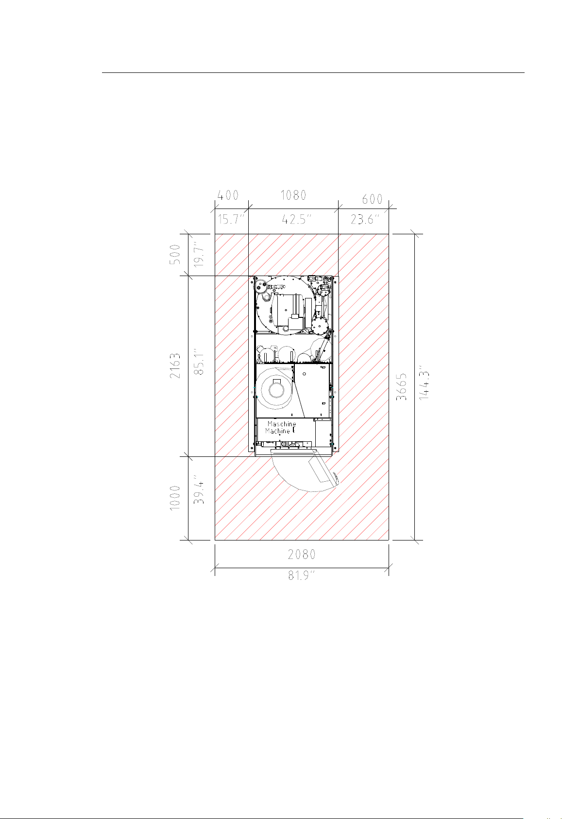
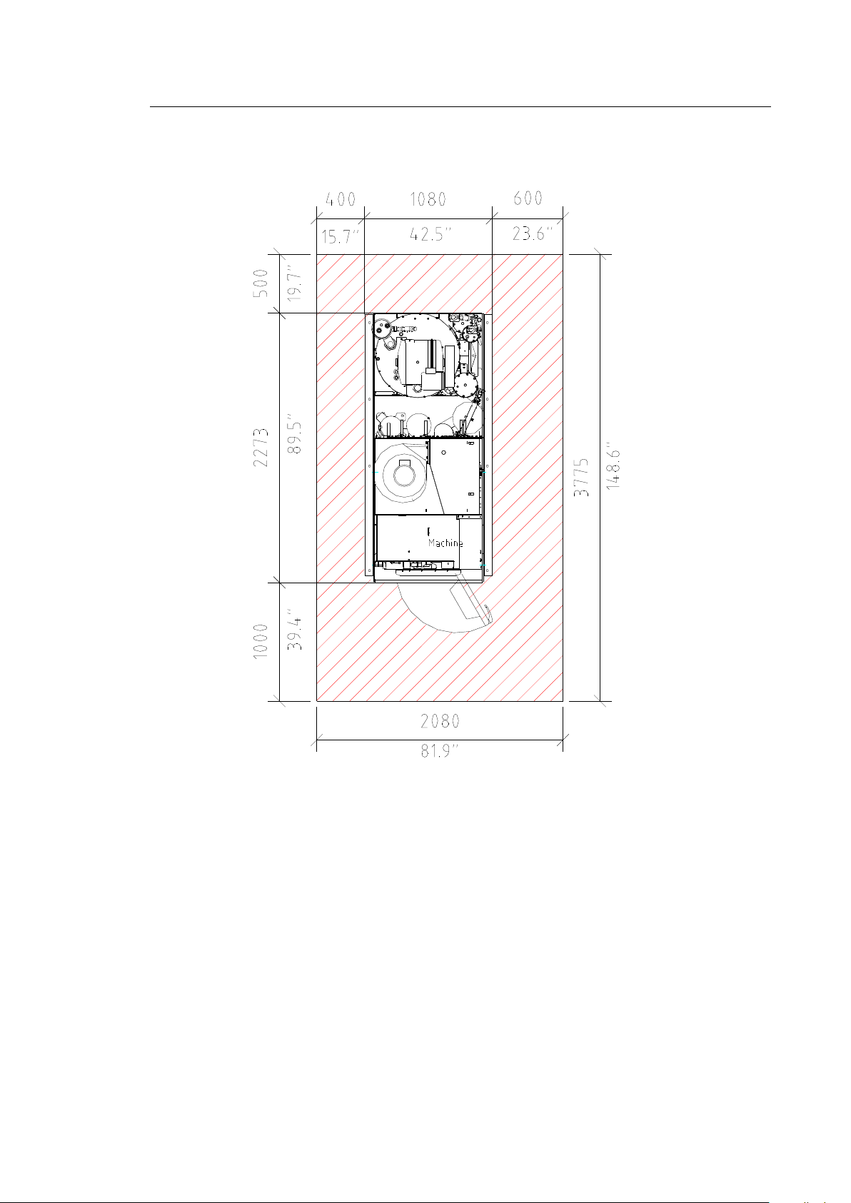
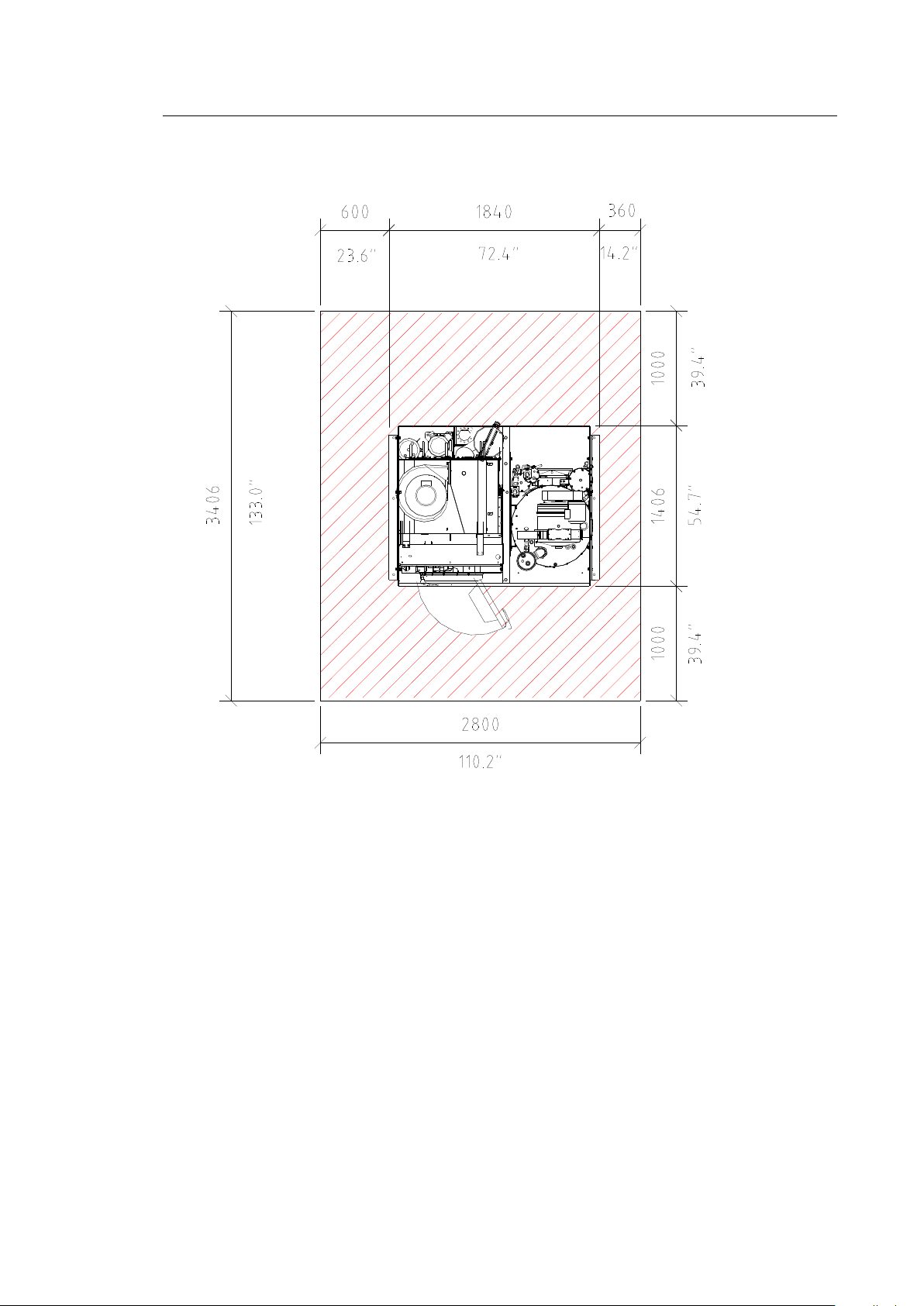
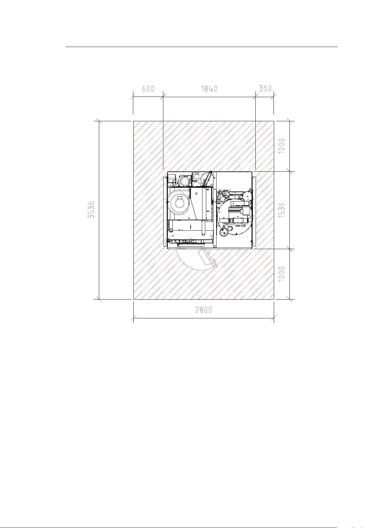
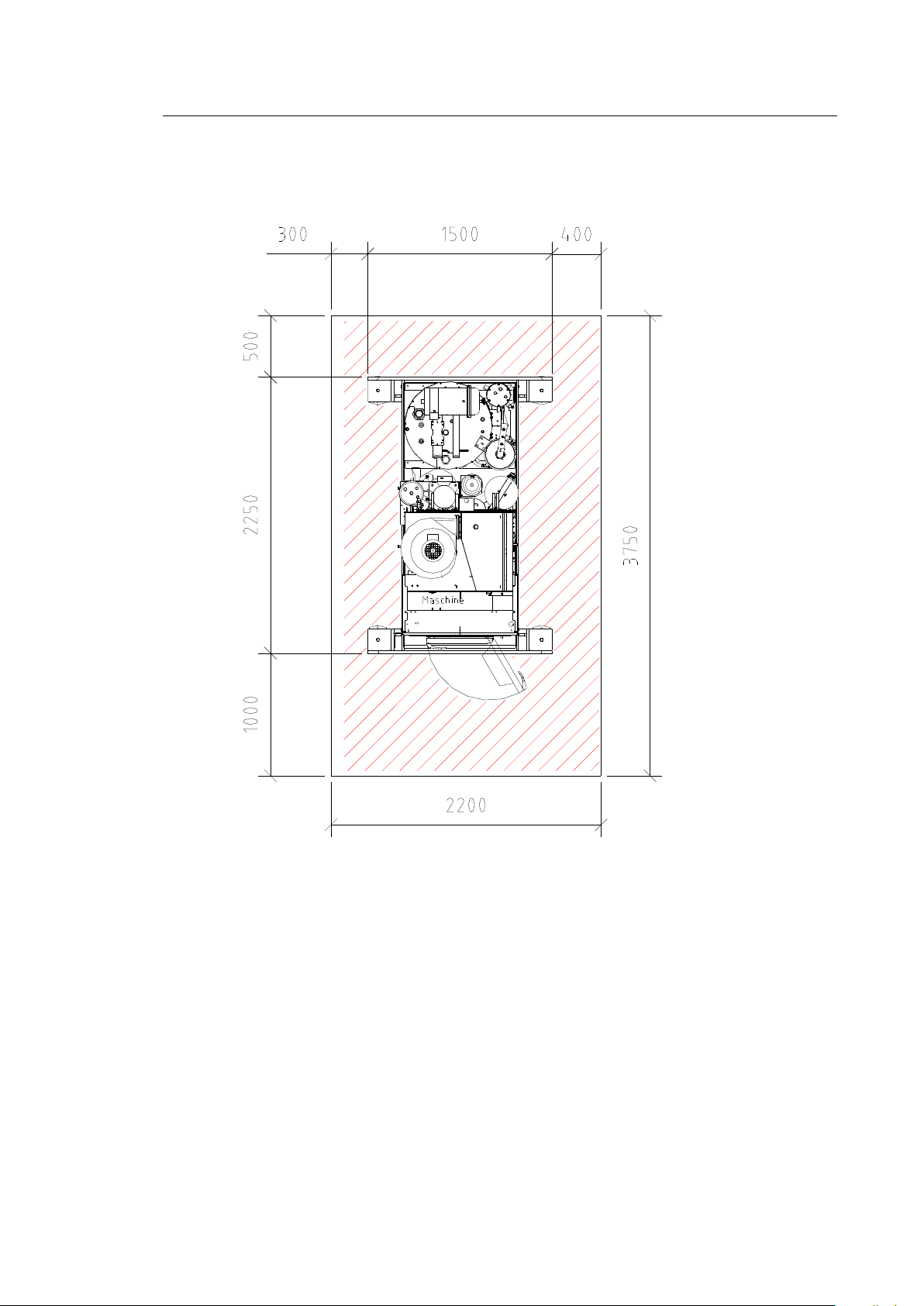
The machine must be accessible for operation and maintenance and repair work (see hatched
areas).
Slimline M12-M15:
707767-08-A
M12-M15-M18
Page 23
15
15
5 Installation 5
Slimline M18:
707767-03-A
M12-M15-M18
Page 24
16
16
5 Installation 5
Crossline M12-M15:
707767-05-A
M12-M15-M18
Page 25
17
17
5 Installation 5
Crossline M18:
707767-04-A
M12-M15-M18
Page 26
18
18
5 Installation 5
Slimline M12-M15 Softpad:
707767-20-0
M12-M15-M18
Page 27
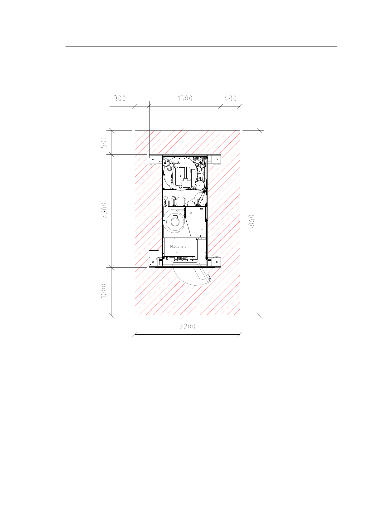
19
19
5 Installation 5
Slimline M18 Softpad:
707767-21-0
M12-M15-M18
Page 28
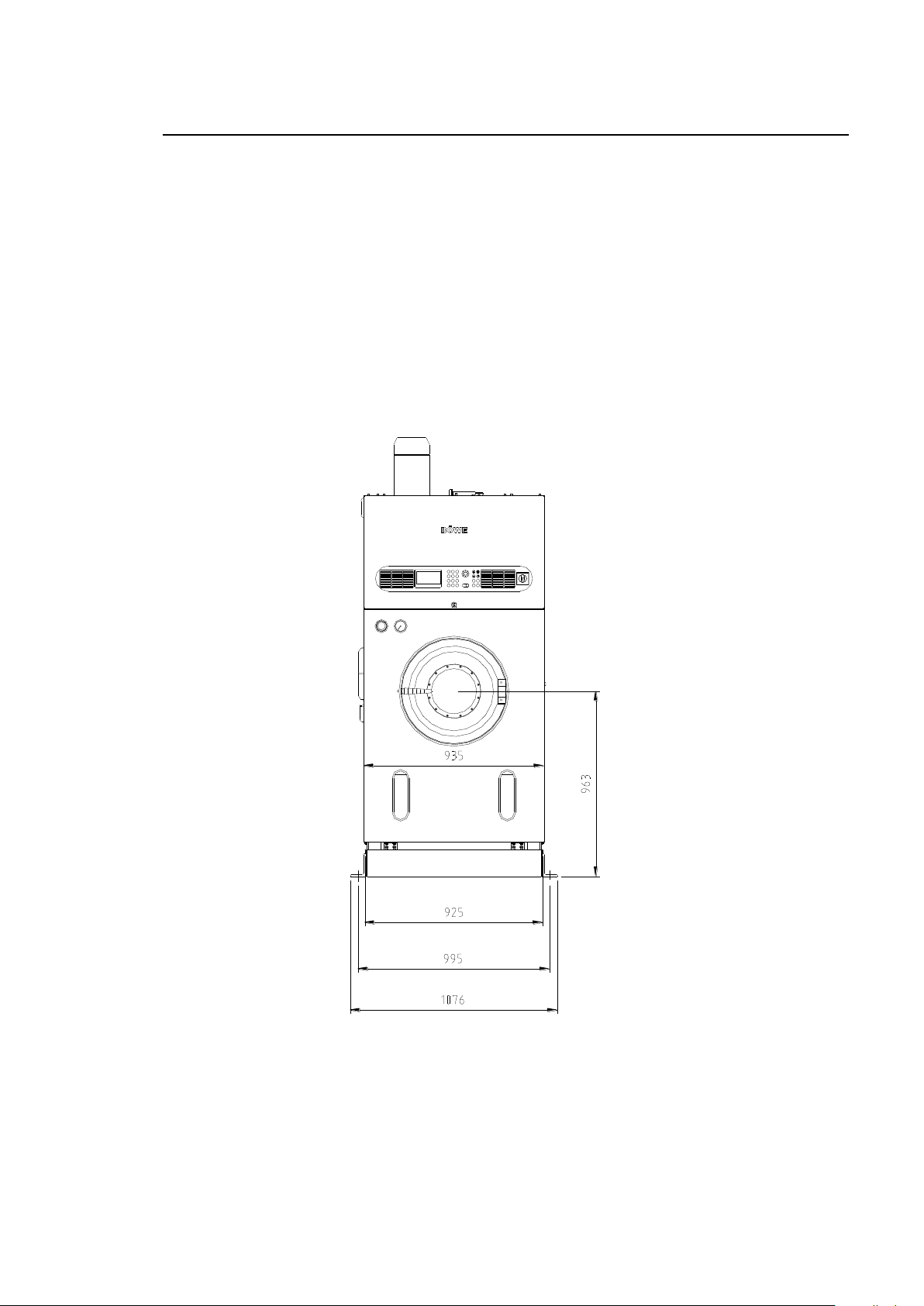
20
1 2
4
7
C80
5
3
BÖWE
E
9
6
START
PROGHOLDHOLD
START STOP
PROG
STOP
Reinigungsprogramme Wartungs- und Hilfsprogramme
M12-M15-M18
Slimline
Crossline
Width without angle bracket
mm (in)
935 (36.8)
1689 (66.4)
Width with angle bracket
mm (in)
1080 (42.5)
1840 (72.4)
Depth M12-M15
mm (in)
2162 (85.1)
1406 (55.3)
Depth M18
mm (in)
2273 (89.)
1536 (60.4)
Height inc. trough
mm (in)
2260 (88.9)
2260 (88.9)
Height inc. trough without fan motor
mm (in)
1995 (78.5)
1995 (78.5)
The dimensions given may differ if special options are used
20
5 Installation 5
5.2.2 Machine Dimensions
707767-25-0
M12-M15-M18
Page 29
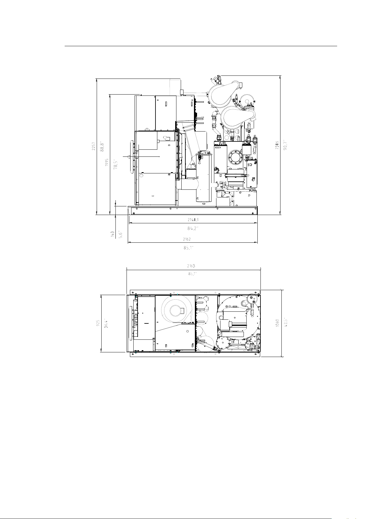
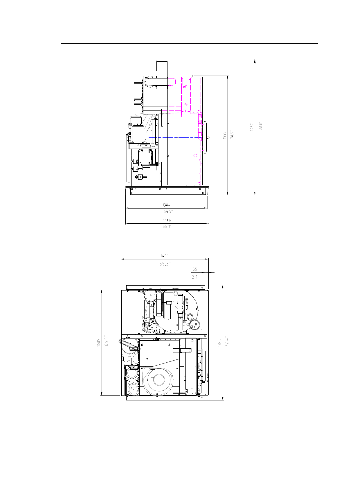
21
21
*
5 Installation 5
Slimline M12-M15
707767-06-A
* only by second filter
707767-07-A
M12-M15-M18
Page 30
22
22
5 Installation 5
Crossline M12-M15
707767-09-A
707767-10-A
M12-M15-M18
Page 31
23
23
*
5 Installation 5
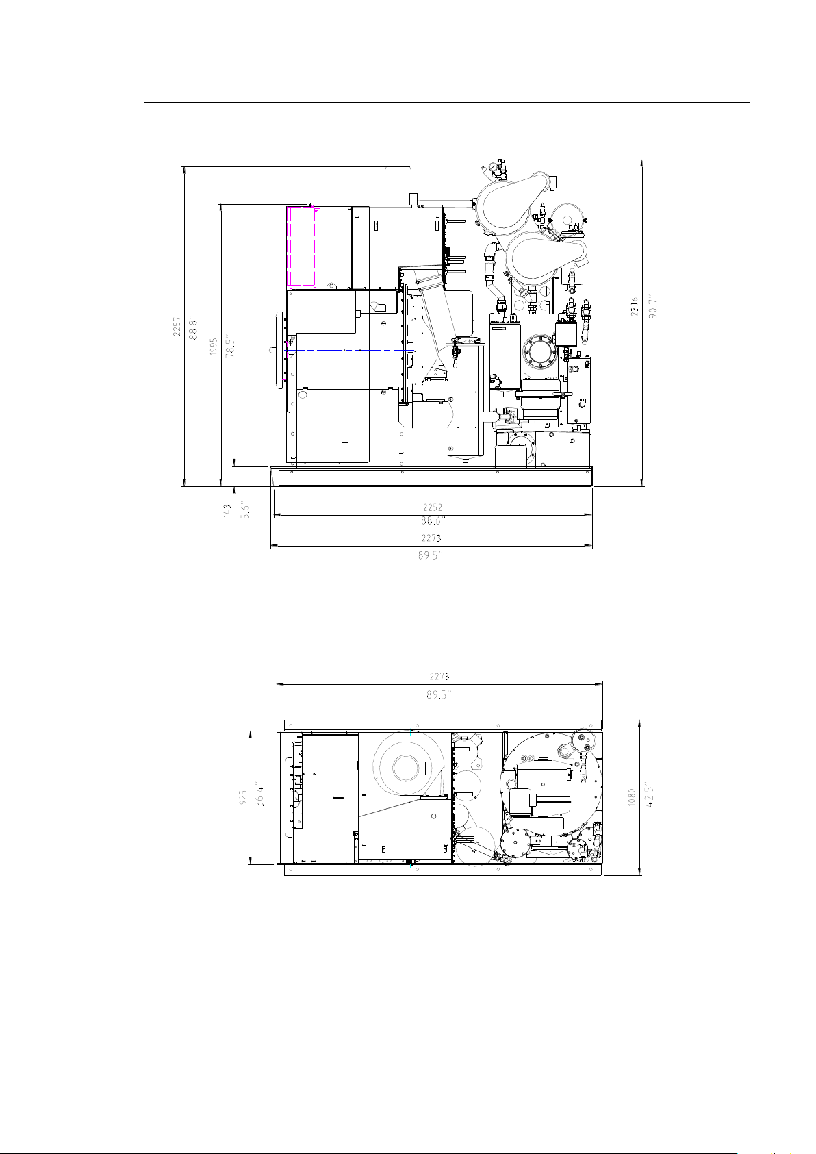
Slimline M18
707767-11-A
* only by second filter
707767-13-A
M12-M15-M18
Page 32
24
24
5 Installation 5
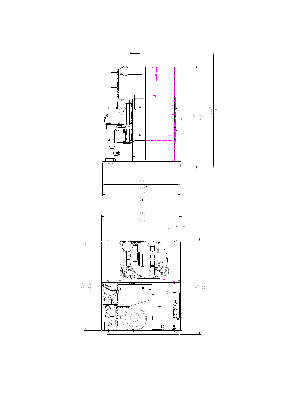
Crossline M18
707767-14-A
707767-15-A
M12-M15-M18
Page 33
25
25
1 2
4
7
C
8
0
5
3
BÖWE
E
9
6
START
PROGHOLDHOLD
START
STOP
PROG
STOP
Reinigungsprogramme Wartungs- und Hilfsprogramme
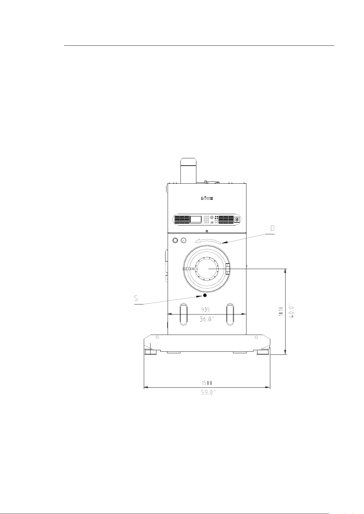
M12-M15-M18 on Softpad
Slimline
Width
mm (in)
1500 (59.0)
Depth M12-M15
mm (in)
2250 (88.5)
Depth M18
mm (in)
2360 (92.9)
Height
mm (in)
2315 (91.1)
Height without fan motor
mm (in)
2050 (80.7)
The dimensions given may differ if special options are used
5 Installation 5
Slimline M12-M15 on Softpad
Installation on Softpad will increase the height of the machine by 55 mm (2.1 in).
M12
M15
M18
707767-26-0
S = Center of gravity
D = Direction of rotation of spinning
M12-M15-M18
Page 34
26
26
*
5 Installation 5
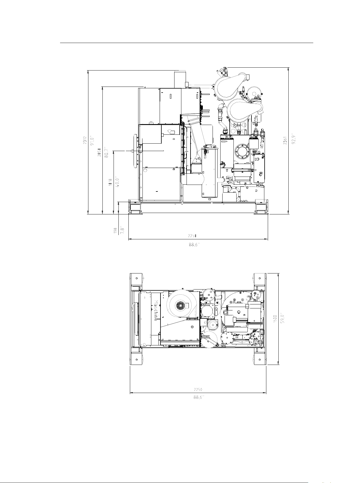
Slimline M12-M15 on Softpad
* only by second filter
707767-22-0
707767-24-0
M12-M15-M18
Page 35
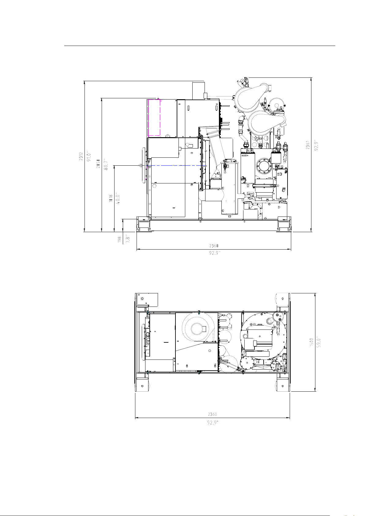
27
27
5 Installation 5
Slimline M18 on Softpad
707767-27-0
707767-28-0
M12-M15-M18
Page 36

28
28
5.3 Floor Load
5.3
Slimline
Crossline
M12
M15
M18
M12
M15
M18
Depth*
mm
inches
1200
47.2
1310
51.6
1420
55.9
1200
47.2
1310
51.6
1420
55.9
Width*
mm
inches
1080
42.5
1080
42.5
1080
42.5
1080
42.5
1080
42.5
1080
42.5
Portion of the floor surface for
force transmission
m
2
ft
2
1.3
14.0
1.41
15.2
1.53
16.5
1.3
14.0
1.41
15.2
1.53
16.5
Weight without solvent
kg
lb
1055
2326
1155
2546
1325
2931
1155
2546
1255
2767
1355
2987
Weight with solvent (stat. load)
kg
lb
1224
2698
1355
2987
1556
3430
1324
2919
1455
3208
1586
3497
Cage centrifugal force (dyn.
load)
N
lbs
8500 **
1874 **
10700 **
2359 **
12800 **
2822 **
8500 **
1874 **
10700 **
2359 **
12800 **
2822 **
Floor load (stat. + dyn. load)
N/m
2
lbs/ft2
15800 **
330 **
17000 **
355 **
18300 **
382 **
16600 **
346 **
17700 **
369 **
18500 **
386 **
5 Installation 5
The place of installation must be designed to comply with the specified floor load. This consists of:
Static load = machine weight + max. solvent filling
Dynamic load = cage centrifugal force with normally distributed, spin-damp garments
Do not forget to take into account the centrifugal forces that arise during the spin processes,
according to the local conditions (ground, supporting walls, etc.). No resonance is permitted.
Please consult building specialists.
5.3.1 Dimensions
* Portion of the machine dimensions that is decisive for the size of the cage centrifugal force and
floor load.
** Calculated with:
- 12 kg-15 kg-18 kg (26.5-33.1 -39.7 lbs) loaded weight, with 50% of this unevenly distributed
- Mixed outer clothing
- EBS
- 600 rpm
- solvent weight 0.77 kg/l
Building specialists will find the best solution, from both a structural and economic point of view, for
the design of the foundation. They take into consideration the system or machine-related conditions
and the local particulars.
Use a load dispatcher frame if the permissible load for your floor is not sufficient.
M12-M15-M18
Page 37
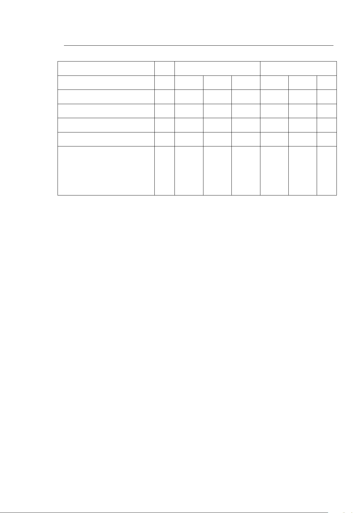
29
29
M12-M15-M18 on Softpad
Slimline on Softpad
M12
M15
M18
Weight without solvent
kg
lbs
1435
3164
1535
3384
1715
3781
Weight with solvent (stat. load)
kg
lbs
1604
3586
1735
3825
1946
4290
Cage centrifugal force (dyn. load)
N
lbs
2200
485
Forces applied, per all 4 point of
support:
Static
Dynamic
N
lbs
N
lbs
4500
992
600
132
5 Installation 5
M12-M15-M18
Page 38
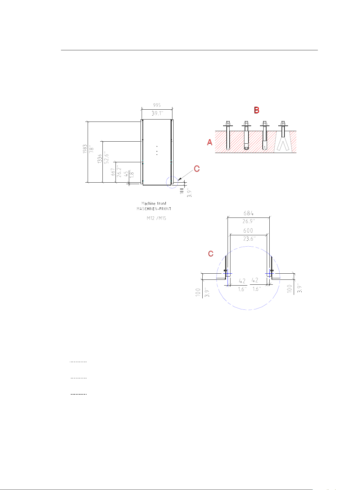
30
30
5.4 Foundation
5.4
5 Installation 5
5.4.1 Foundations Dimensions
Slimline M12-M15
707758-14-A
A Reinforced concrete
B Examples for fixing the machine in place
C Distance to the next machine
M12-M15-M18
Page 39
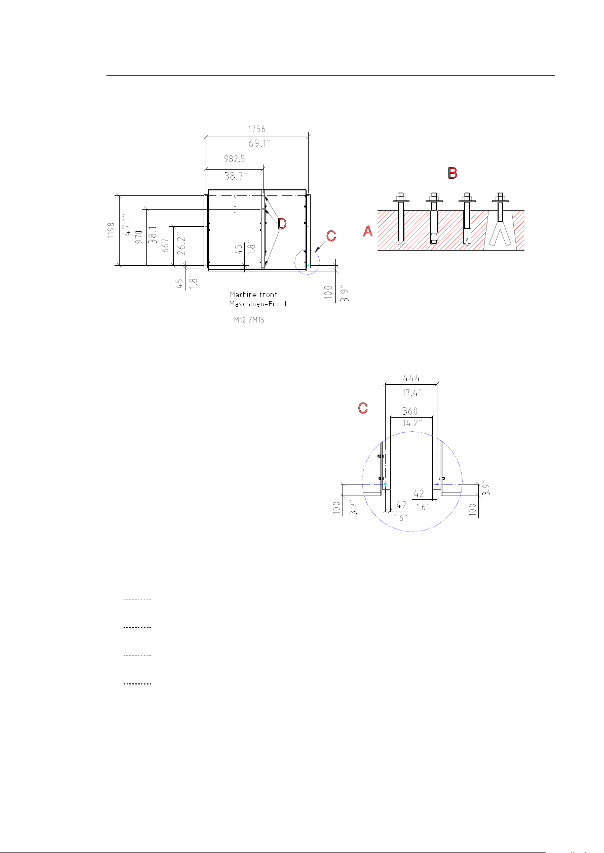
31
31
5 Installation 5
Crossline M12-M15
707758-15-A
A Reinforced concrete
B Examples for fixing the machine in place
C Room floor surface - concrete slab
D Use M12 x 300 foundation anchors
M12-M15-M18
Page 40
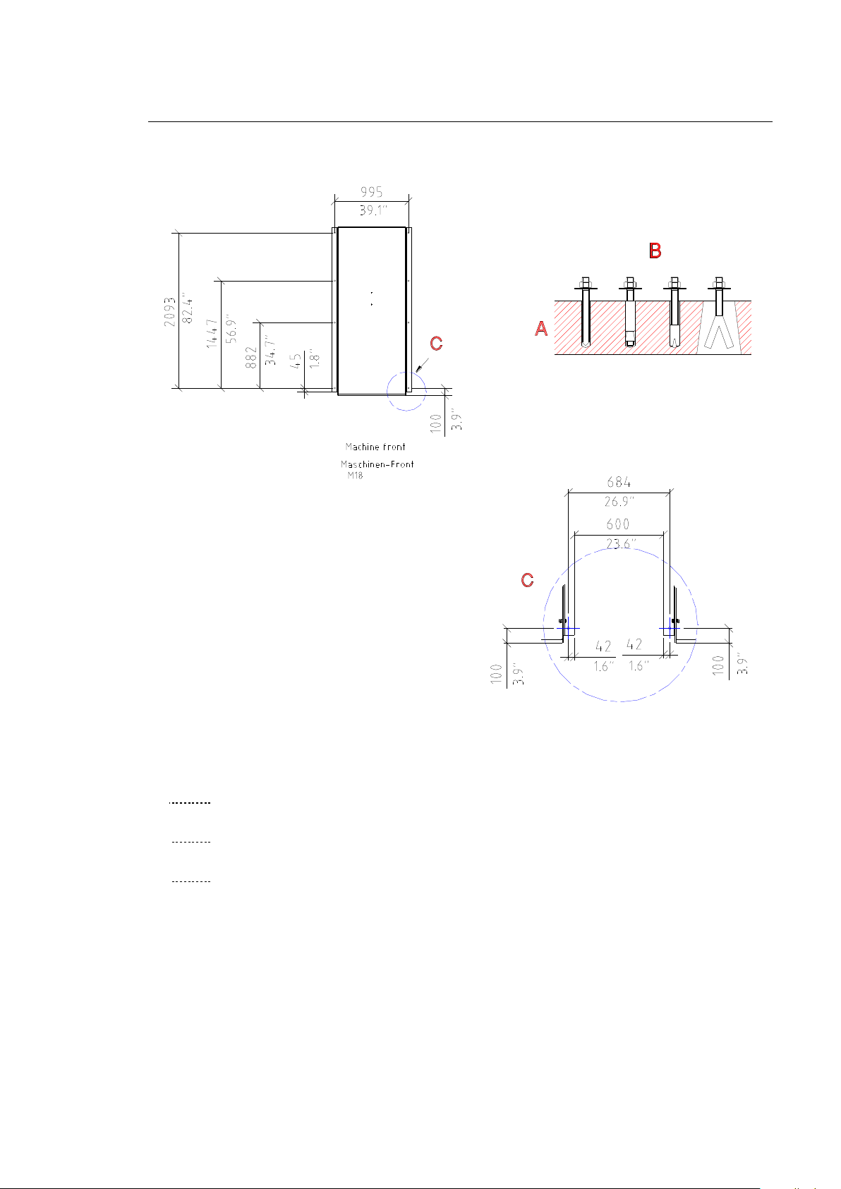
32
32
5 Installation 5
Slimline M18
707758-26-A
A Reinforced concrete
B Examples for fixing the machine in place
C Room floor surface - concrete slab
M12-M15-M18
Page 41
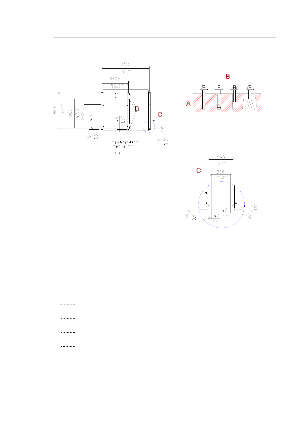
33
33
5 Installation 5
Crossline M18
Machine front
707758-27-A
A Reinforced concrete
B Examples for fixing the machine in place
C Room floor surface - concrete slab
D Use M12 x 300 foundation anchors
M12-M15-M18
Page 42
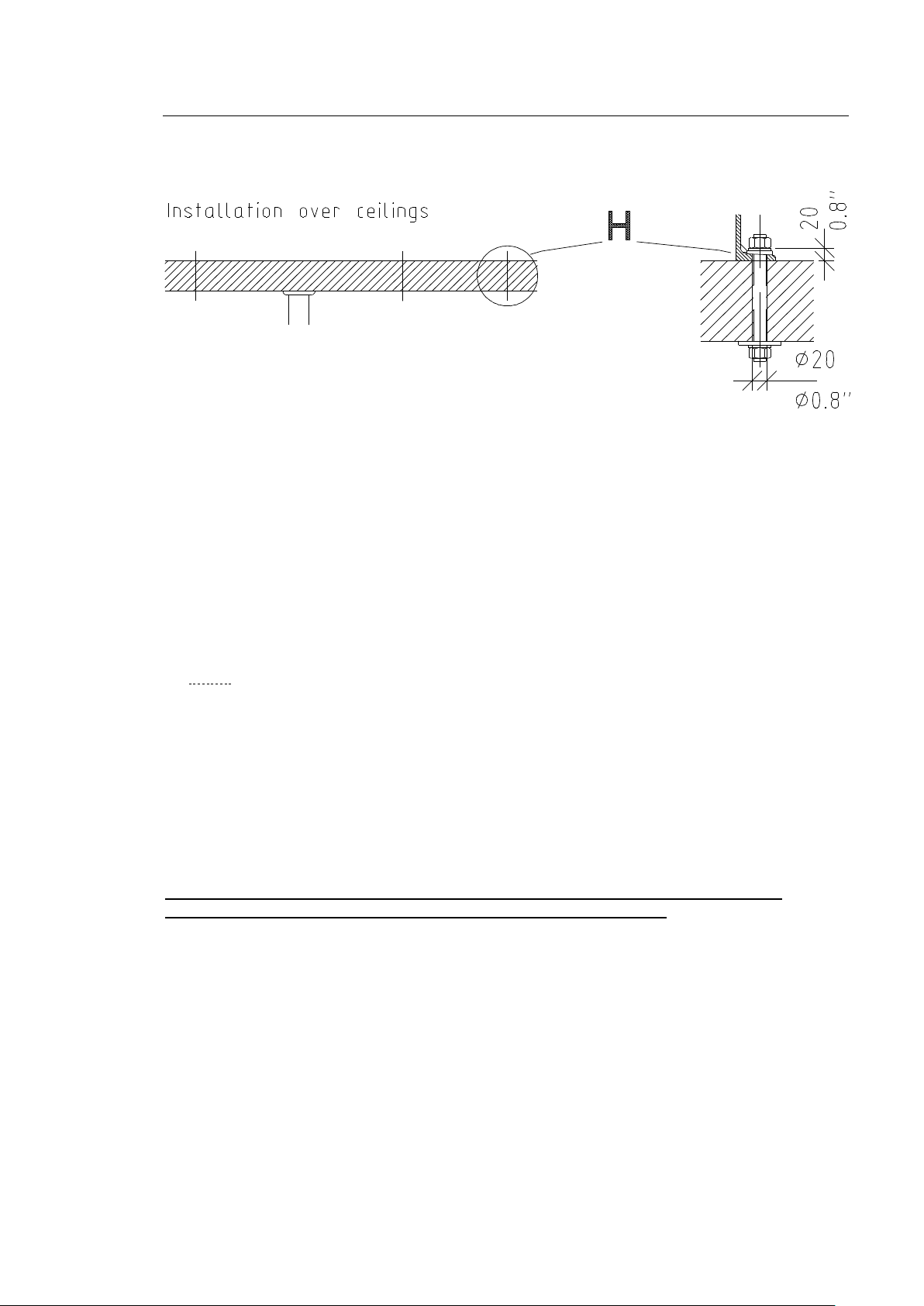
34
34
5 Installation 5
703871-22-0
H Ceiling bore holes ( 20 mm or 3/4 in) for through bolt, length depending on the
thickness of the ceiling. Support if necessary
5.4.2 Anchoring Surface
Correct anchoring is extremely important for low-noise, fault-free operation. When installing
on the foundation, the use of stone bolts is preferable.
The anchoring surface must be horizontal and level.
Never place the machine directly on felt, bituminous coatings, rubber or cork.
On uneven concrete floor, you must level the machine or safety trough with leveling
plates and even out the supporting surface with filler (epoxy resins).
5.4.3 Sound and Vibration Insulation
Consult with building and insulation specialists with regard to the use of special foundations,
dampers, spring cups or similar devices for special vibration insulation.
M12-M15-M18
Page 43
35
6 Fixing the Machine in Place
6
6.1 Machine Trough
6.1
6.2 Anchoring Methods
6.2
M12
The machine trough is a permanently integrated component of the machine.
Collecting capacity: M12-M15: Slimline: 180 l (47.6 US gal), Crossline: 213 l (56.2 US gal)
M18: Slimline: 190 l (50.1 US gal), Crossline: 233 l (61.5 US gal)
Material: St1203 /1.0330.03 /3 mm(.1 in) /S235 JRG2 painted
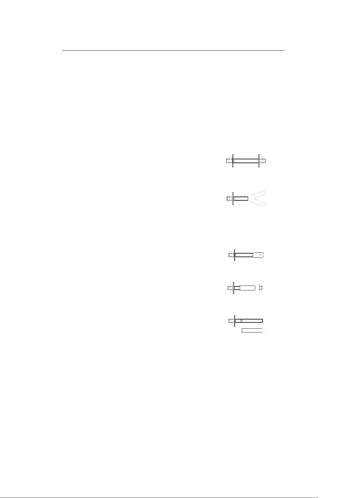
Alternatively, you can also use the following anchoring methods to fix the machine in place:
For ceiling installation:
- Through bolts (threaded rods)
with washers and M12 nuts.
For foundation installation:
- Stone bolts (length 100 mm/3.9 in) for cementing into
recessed or mortised holes
(The screws are not permitted to be longer than the
thickness of the foundation).
or
35
- Heavy-duty plug with threaded rod
for deeper bore holes
or
- Safety expansion anchors for use in bored holes
or
- Adhesive plugs/shear connectors.
703871-25-0
Thread for all anchoring methods: M 12
Quality: Property class 8.8 - DIN 267
The fixing nuts must be self-locking, with quality that complies with DIN 985.
We will not accept any liability for damages that result from failure to comply with our
recommendations and instructions.
Attention:
Pay attention to the floor load of the machine floor space.
The bore holes must be drilled deeply enough that the plug stretches in the concrete.
M12-M15-M18
Page 44

36
36
6 Fixing the Machine in Place 6
Anchoring:
Cementing in stone bolts:
Steps:
Insert stone bolts in the holes of the angle bracket with spring washers and nuts.
Level the machine. If the floor is uneven, level the machine with wedges and even out the surface with
filler (epoxy resins).
Fill anchoring holes with fast-drying cement.
After it sets, tighten the nuts evenly.
Safety expansion anchor:
Steps:
Position the machine in its intended position.
Use the holes of the angle bracket as a drilling template.
Pre-drill with a 14 mm (.5 in) stone drill. Minimum drilling depth 100 mm (3.9 in). Drill in vertically!
Remove the machine or angle bracket.
Drill the holes 140 mm (5.5 in) deep with the 18 mm (0.7 in) stone drill.
Remove the nuts and washers of the expansion anchor. Shorten the upper plug brush.
Insert the anchor in the bore hole.
Position the machine or attach the angle bracket and level.
If the floor is uneven, level the machine with wedges and even out the surface with filler (epoxy
resins).
Tighten the nuts on the anchors evenly.
Threaded rod (bored through ceiling)
Steps:
Position the machine in its intended position.
Use the holes of the angle bracket as a drilling template.
Pre-drill with 14 mm (.5 in) stone drill. Drill in vertically!
Remove the machine or angle bracket.
Use a 20 mm (.8 in) stone drill to drill the holes for normal ceiling installation
(See foundation schematic, Point 5.4)
Position the machine or attach the angle bracket and level.
The angle bracket must lie flat against the ceiling.
If the floor is uneven, level the machine with wedges and even out the surface with filler (epoxy
resins).
M12-M15-M18
Page 45

37
37
6 Fixing the Machine in Place 6
Adhesive plugs/shear connector
Steps:
Position the machine in its intended position.
Use the holes of the angle bracket as a drilling template.
Pre-drill with a 14 mm (.5 in) stone drill. Drill in vertically!
Remove the machine or angle bracket.
Bore holes: Drill the diameter and depth according the information provided by the
plug manufacturer and blow out any dust..
For further steps, refer to the information provided by the plug manufacturer.
Note the hardening time.
Position the machine or attach the angle bracket and level.
If the floor is uneven, level the machine with wedges and even out the surface with filler (epoxy
resins).
Tighten the nuts evenly.
M12-M15-M18
Page 46
38
38
7 Connection
7
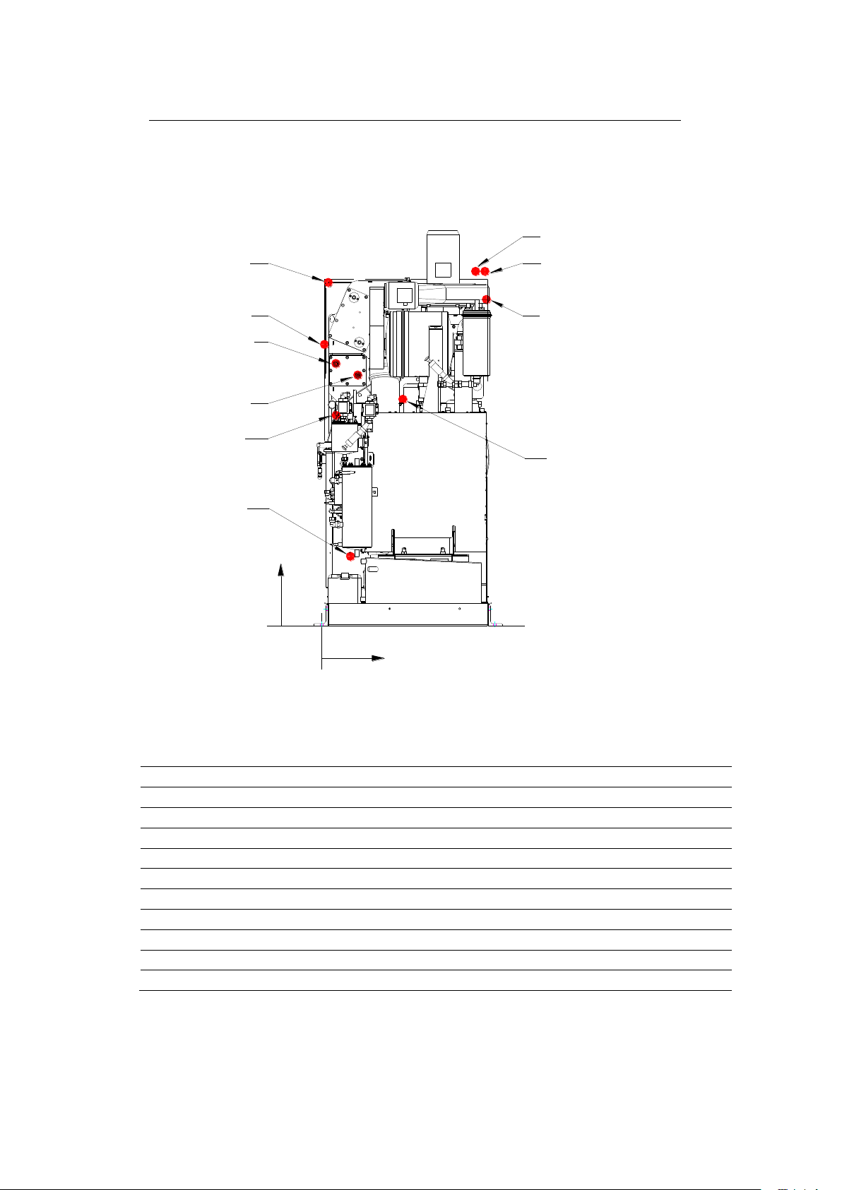
7.1 Dimensioned Drawing of the Machine Connections
7.1
Item
Medium
NW
mm
Inch -X-
mm (in)
-Y-
mm (in)
1
Steam heater battery machine
15
1/2
85 (3.3)
1495 (58.8)
2
Steam distillation
15
1/2
470 (18.5)
1290 (50.7)
3
Condensate heater battery machine
15
1/2
210 (8.2)
1430 (56.3)
4
Condensate distillation
15
1/2
170 (6.6)
420 (16.5)
5
Cooling water inlet
20
3/4
880 (34.6)
2030 (80)
6*
Cooling water outlet, distillation
20
3/4
920 (36.2)
2030 (80)
7
Cooling water outlet, refrigeration unit
20
3/4
950 (3.4)
1860 (73.2)
8
Compressed Air
8
1/4
20 (0.8)
1600 (63)
9
Electric connection (front side top)
- 40 (1.6)
1950 (76.7)
10
Ventilation waterseparator /sluice tank
22 90 (3.5)
1220 (48)
--
Still rake out – pump out
- - -
-
Slimline M12-M15-M18
707767-16-0
We reserve the right to change dimensions!
* There must be a measuring potentiometer installed (on the machine) between
the machine and customer wiring system.
M12-M15-M18
Page 47
39
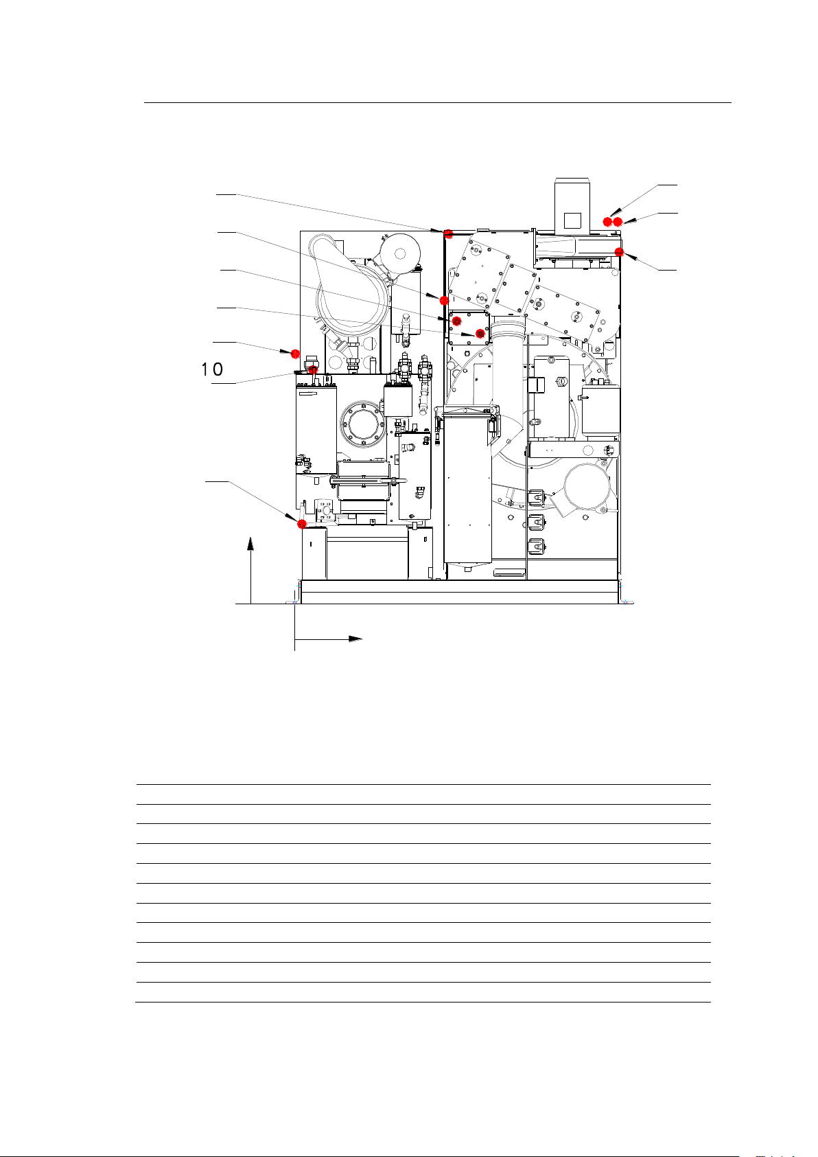
Item
Medium
NW
mm
Inch -X-
mm (in)
-Y-
mm (in)
1
Steam heater battery machine
15
1/2
860 (33.8)
1495 (58.8)
2
Steam distillation
15
1/2
10 (0.4)
1320 (52)
3
Condensate heater battery machine
15
1/2
980 (38.5)
1430 (56.3)
4
Condensate distillation
15
1/2
40 (1.5)
420 (16.5)
5
Cooling water inlet
20
3/4
1660 (65.3)
2030 (80)
6*
Cooling water outlet, distillation
20
3/4
1710 (67.3)
2030 (80)
7
Cooling water outlet, refrigeration unit
20
3/4
1720 (67.7)
1860 (73.2)
8
Compressed Air
8
1/4
800 (31.5)
1600 (63)
9
Electric connection (front side top)
- 820 (32.3)
1950 (76.7)
10
Ventilation waterseparator /sluice tank
22 100 (3.9)
1220 (48)
--
Still rake out – pump out
- - -
-
39
7 Connection 7
Crossline M12-M15-M18
707767-17-0
We reserve the right to change dimensions!
* There must be a measuring potentiometer installed (on the machine) between
the machine and customer wiring system.
M12-M15-M18
Page 48
40
40
7.2 Lines and Pipelines
7.2
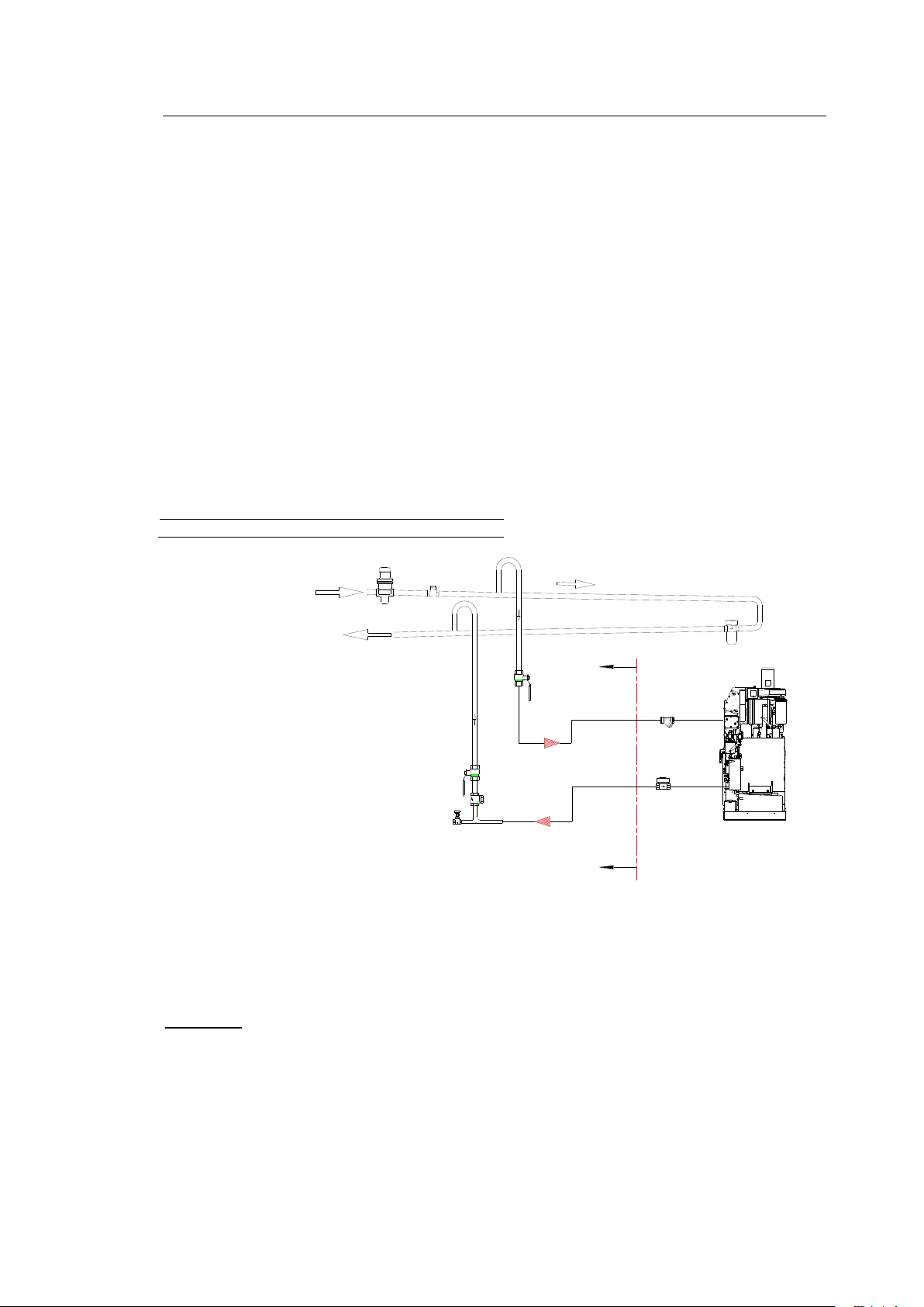
Drying
0.6 kg/min (1.3 lbs/min)
Distillation
0.6 kg/min (1.3 lbs/min)
7 Connection 7
Connect the customer-supplied supply and drain lines according to the information in the
dimensioned drawing. Steam, condensate, compressed air and water must be equipped with
stop valves. Follow DIN 1988 when connecting the water. To avoid transmission of
structure-borne noise, you can connect the pipelines with a spacer of flexible metal
tubing and insulate the pipe holders.
7.2.1 Steam
Install the wiring system and connections in such a way that they are insulated.
Operating pressure 4 - 5 bar (58 - 72.5 psi) saturated steam.
If the admission pressure is more than 5 bar (72.5 psi), build in a reducing valve with
pressure gauge and safety valve.
Peak steam demand (large steam generator):
M12, M15, M18
1 = Reducing valve
2 = Vacuum breaker
3 = Descending slope
4 = Steam trap
5 = Stop valve
6 = Non-return valve
7 = Drain
8 = Customer side
707767-12-0
7.2.2 Condensate
Install condensate line so that it slopes away from the machine, if possible. If there is an
ascending slope, provide a non-return valve and drain at the lowest point.
Attention:
Condensate counter-pressure must be at least 1.5 bar (21.8 psi) under the incoming
steam pressure.
M12-M15-M18
Page 49

41
41
Drying/detergent solution cooler
9 l/min (2.4 US gal/min)
Distillation
10l/min (2.6 US gal/min)
7 Connection 7
7.2.3 Cooling Water Supply
7.2.3.1 Mains water supply
The cross-sections of the lines to the machine should not get smaller and should be without
bends and curves, if possible. The heat balance of the machine has been optimally designed
for cooling water with an inlet temperature of 12 °C (53.6 °F) and uniform pressure of 2 - 4 bar
(29 - 58 psi). (Minimum pressure 2.0 bar (29 psi), maximum pressure 6.0 bar (87 psi)
A manually operated stop valve should be fitted.
Peak cooling water demand 2 - 4 bar (29 - 58 psi) (12 °C/53.6 °F):
M12, M15, M18
According to DIN 1988, a water flowback stop and venting device must be installed on
machines in the Federal Republic of Germany.
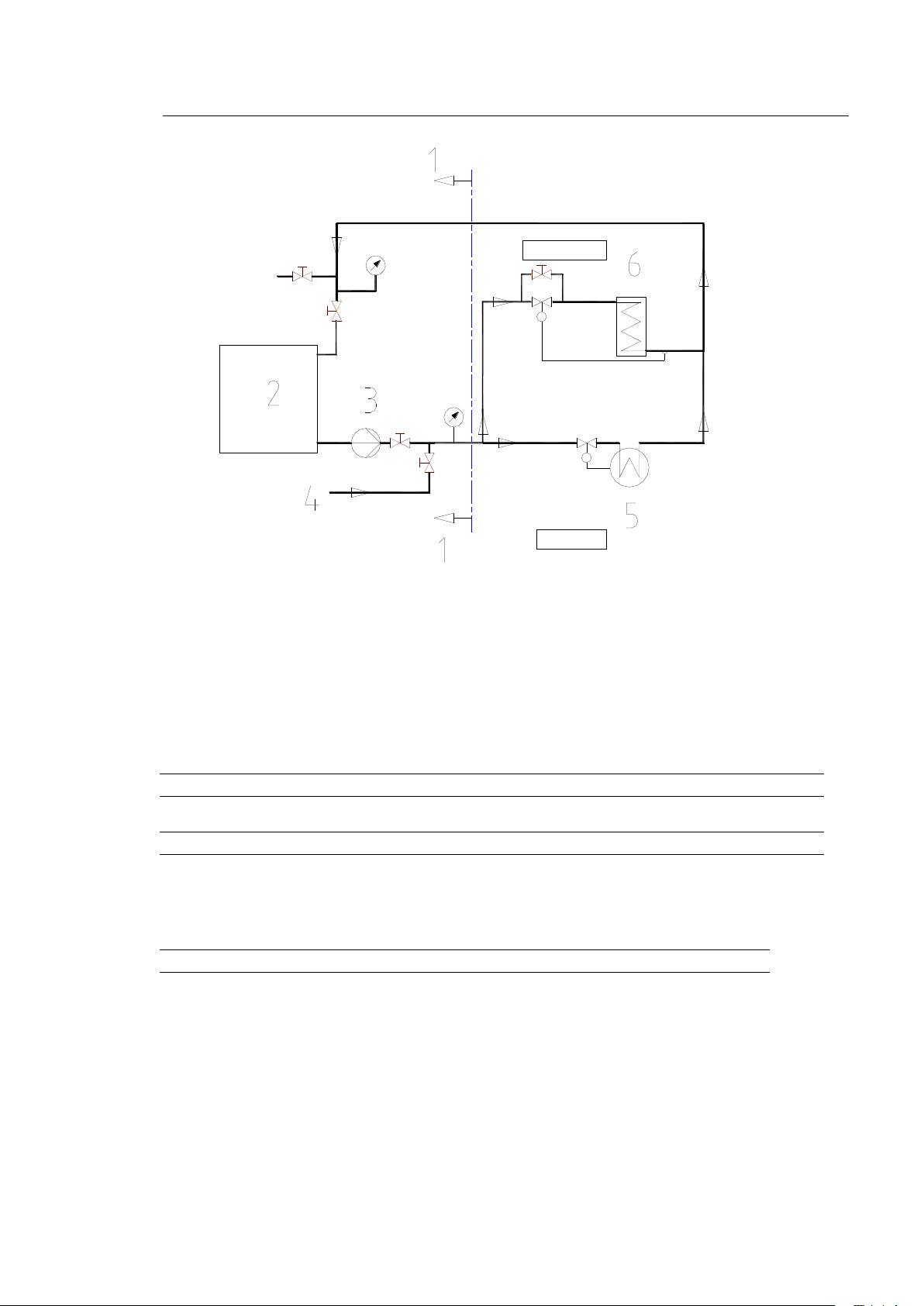
7.2.3.2 Cooling Tower Operation
For cooling tower or recooling operation, the nominal width of the feeding and drain lines must be
dimensioned to be larger than the nominal width of the circulation pump or must be dimensioned
according to the pump.
Inlet temperatures are not allowed to exceed 24 °C/ (75.2 °F) because otherwise the solvent
consumption increases and the drying times are also longer.
Cooling water inlet temperatures that are too high can also overload the refrigeration unit.
The water pressure must be adapted to the high inlet temperature, up to double the peak demand.
In cooling tower or recooling operation, correct installation is especially important.
Consequently, some of the things that must be kept in mind are the cooler capacity, mains
water supply switch-over, stored cooling capacity, pump size and cooling water by-pass.
The cooling water regulator (water economizer valve) for the machine and distillation system
must be corrected or avoided with a bypass (manual valve) (= continuous water flow).
The cooling water supply or the backfeeding to the recooling unit must come from the mains
water system or from a soft water system.
M12-M15-M18
Page 50
42
42
Data for temperatures up to 24 °C (75.2 °F)
(Nominal width NW at least 25 mm (1 inch)):
M12
M15
M18
Pump throughput
m3/h *
US gal/h
1.7
449.1
2.2
581.2
2.7
713.3
Pump pressure
bar
psi
4-6
58 – 87
4-6
58 - 87
4-6
58 - 87
Heat to be dissipated over cooling water* :
M12
M15
M18
kJ/cycle (approx)
24800
30400
35900
Distillation
Machine
7 Connection 7
1 = Customer side 5 = Refrigeration unit
2 = Cooling tower 6 = Condenser
3 = Circulation pump
4 = Mains water supply
707770-21-0
* refers to water without additives
Also refer to the separate installation and operating instructions for the rechilller.
M12-M15-M18
Page 51
43
43
It must be ensured that the venting does not lead to areas with high
explosion risks or to ignitation sources.
7 Connection 7
7.2.4 Cooling Water Outlet
The cooling water leaving the system can be directed to the sewer system, reused and recooled
because it circulates through the machine in a closed system and does not come into contact
with the solvent. You should endeavor to reuse the cooling water.
7.2.5 Compressed Air
The operating pressure is 6 bar (87 psi). The machine is equipped with a compressed air
reducing valve, pressure gauge and compressed air water separator. The line pressure should
be 10 - 12 bar (145 - 174 psi).
7.2.6 Process Water
Empty the process water collecting tank daily.
Dispose of the contents according to the regulations for your country.
7.2.7 Aeration Lines
The venting ducts of the machine must lead without diminished cross section into the open or via
open funnel and cock valve to the room venting system (if existing).
M12-M15-M18
Page 52
44
44
7.3 Electrical Connection
7.3
Caution
Only trained electricians are permitted to work on the electrical
system.
M12-M15-M18
Operating load
kW
Max. current
A
Fuse
A
400 V, 50 Hz
Steam /electric without distillation
7 /16
25 /38
32 /50
Steam /electric with distillation
8 /27
26 /53
32 /63
230 V, 60 Hz
Steam /electric without distillation
7 /16
43 /65
50 /80
Steam /electric with distillation
8 /27
45 /91
50 /100
7 Connection 7
Note the supply voltage (on the nameplate). Connect L1 /L2 /L3, neutral and ground wires with
the appropriate cross section and fusing. Pass the cable into the switch panel through the PVC
screwed union provided and connect to terminal.
Main switch connection
The main switch must be connected at the customer with an approved cable. Strip the cable right
before the main switch only. Do not lay stripped cable in the cable trunking.
Ground-fault circuit interrupter at the customer
In case of a fault current breaker integrated in the building it is recommandable
to make sure, if it is applicable to the machine with variable speed drive.
M12-M15-M18
Page 53
45
45
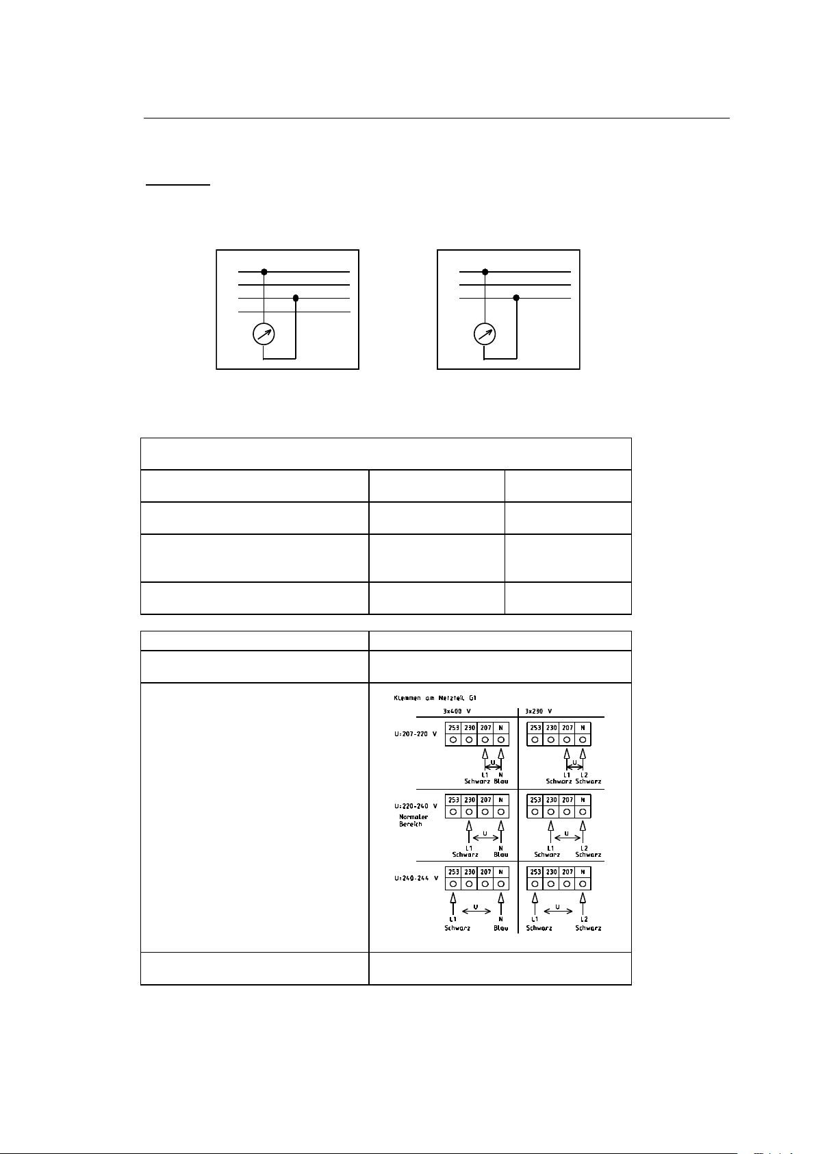
1. Main supply (according to DIN IEC 38):
Range
Primarily 400-V
power system
Primarily 230-V
power system
Not allowed; requires external
adjustment
< 360 V
< 207 V
Normal working range
MIN: -10.0 %
MAX: + 6.0 %
360 V to 424 V
207 V to 244 V
Not allowed; requires external
adjustment
> 424 V
> 244 V
Range
Primarily 230-V power system
Not allowed; requires external
adjustment
< 207 V
Normal working range
207 V to 244 V
703904-18-0
Not allowed; requires external
adjustment
> 244 V
L1
L2
L3
U
3x230V
L1
L2
L3
N
U
3x400V
7 Connection 7
7.3.1 Permissible Voltage Range
Attention:
The power supply must be measured at the machine before you turn the machine on. If it
deviates from the standard voltage, you must adapt the machine to the local voltage with an
autotransformer.
When making the electric connections for a drycleaning machine, you must observe the
following voltage ranges:
M12-M15-M18
Page 54
46
46
7 Connection 7
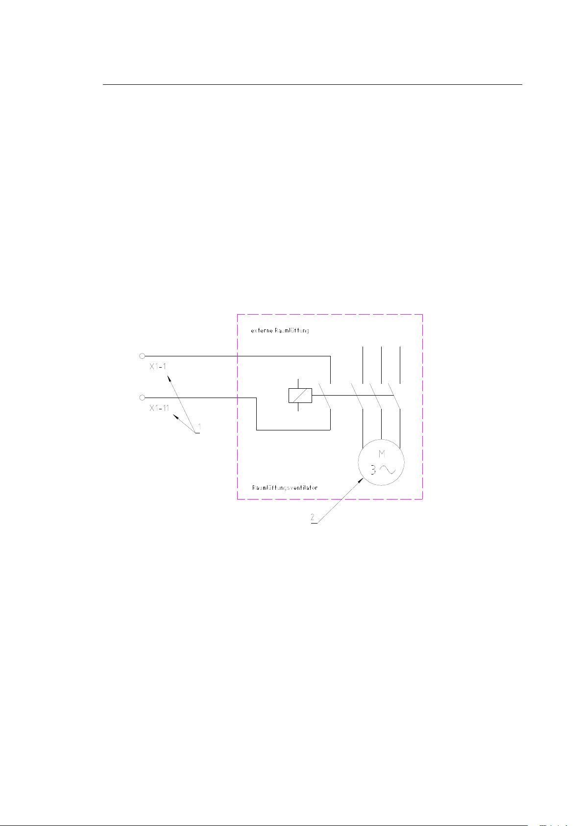
7.3.2 Control of Room Ventilation
If there is already a room ventilation system, you can couple the automatic machine actions with
the ventilation system.
In this case, the machine starts only when the room ventilation has been turned on.
Recommendation for renewing the room air:
The room ventilation must be sufficient to meet the requirements for your country.
Example: BGR 500 chapter 2.14
The minimum requirement for renewing the room air is achieved when the dissipated amount of
air in m3 /h is equal to 60 times the numerical value of the standard loaded amount in garments
in kg. The air renewal rate can be limited to 5 per hour if the calculation results in a larger
numerical value.
703904-17-0
1 = Terminals in switch panel
2 = External room ventilation - room ventilation fan
M12-M15-M18
Page 55
47
8 Important Information
8
8.1 First Startup
8.1
Attention: Before opening the switch panel or removing paneling,
set the main switch to "0".
Attention: This solvent is a powerful fat solvent. Wear gloves when
handling solvent and apply protective skin ointment to hands when
done. Do not smoke.
Immediately change any clothing that is wet with solvent.
If you get solvent in your eyes,:
rinse them thoroughly with water
and see a doctor.
If there is no suction from the pump, pour about 5 liters (1.3 US gal) of
solvent into the button trap. Check that the direction of rotation is
correct.
The BÖWE Customer Service department is responsible for carrying out the first startup.
8.1.1 Preparatory Work
Set up the supply systems (electrical current, cooling water, compressed air, steam and
condensate lines).
8.1.2 Filling Machine with Solvent
You must use solvents that have a flash point that is higher than the temperature stated on the
machine nameplate.
The amount of solvent needed is:
Machine M12 tank I: approx.60 l / 15.8 US gal
Machine M15 tank I: approx.75 l / 19.8 US gal
Machine M18 tank I: approx.90 l / 23.8 US gal
Machine M12 tank III: approx.60 l / 15.8 US gal
Machine M15 tank III: approx.75 l / 19.8 US gal
Machine M18 tank III: approx.90 l / 23.8 US gal
Total filling amount M12: approx. 220 l / 58.1 US gal
Total filling amount M15: approx. 260 l / 68.7 US gal
Total filling amount M18: approx. 300 l / 79.2 US gal
Total filling amount M12 for the 3-tank model: approx. 280 l / 73.9 US gal
Total filling amount M15 for the 3-tank model: approx. 330 l / 87.1 US gal
Total filling amount M18 for the 3-tank model: approx. 380 l / 100.4 US gal
For machines with 2 economy filters: + 40 l (10.5 US gal)
For machines with 2 economy filters and 1 cartridge filter: + 55 l (14.5 US gal)
47
M12-M15-M18
Page 56
48
48
Attention: Even empty containers can still hold solvent residues.
Therefore tightly seal the container (barrel) again and
store or dispose of in accordance with regulations!
8 Important Information 8
To fill without emissions, proceed as follows:
- Remove the screw cap on the pump line.
- Connect a hose between the barrel and pump suction side.
- Open the ball valve.
- Start program P51
- The tanks fill up, with one overflowing into the other.
- Watch the level of the liquid in the tanks and stop
program P51 when the tanks are full or when enough solvent has been filled in.
- Close the ball valve.
- Remove the connecting lines to the barrel.
- Screw the cap back on to the pump line.
With an additional 3rd tank:
- first fill up tank 1 and tank 2 (using program P51)
- fill tank 3 with P67
- fill tank 2 once more with P51
If may be necessary to refill with solvent after the filter is filled each time you replace a filter.
8.1.3 Refilling Solvent
Follow the procedure given in Point 8.1.2 for routine refilling of solvent.
M12-M15-M18
Page 57
49
49
8.2 Refrigeration Unit
8.2
Attention:
No cooling agent is allowed to escape into the atmosphere during
operation, servicing work and decommissioning of refrigeration units.
You must keep a record of the quantities of cooling agent used and
present this record to the authorities upon demand.
Only people who have the necessary special knowledge and technical
equipment are authorized to service and decommission refrigeration
units.
8 Important Information 8
8.1.4 Vacuum Pump
The vacuum pump does not need any operating liquid and starts automatically after the machine is
turned on.
M12-M15-M18
Page 58
50
50
9 Technical Specifications
9
Machine
Heating
M12
Steam
M12
Electric
Filling quantity
kg (lb)
12 (26.5)
12 (26.5)
Cage volume
l/ US gal
240 (63.4)
240 (63.5)
Cage diameter
mm (in)
820 (32.3)
820 (32.3)
Cage depth
mm (in)
460 (18.1)
460 (18.1)
Load diameter
mm (in)
400 (15.7)
400 (15.7)
Cleaning speed/drying speed
RPM
40
40
Spinning speed:
RPM
600
600
Max. g-factor 165
165
Low level
l/ US gal
30 (7.9)
30 (7.9)
High level
l/ US gal
60 (15.8)
60 (15.8)
Operating load (max. at 400 V,50Hz)
Without distillation
kW
7
16
With distillation
kW
8
27
Connected loads:
Compressor capacity
kW
4.0
4.0
Fan capacity HLL /NLL
kW
2.5 /1.85
2.5 /1.85
Solvent pump capacity
kW
1.1
1.1
Cage drive capacity
kW
3.7
3.7
Filter drive capacity
kW
0.55
0.55
Vacuum pump capacity
kW
0.37
0.37
Steam generator capacity
kW
-
10 /8.5
Dimensions:
Machine:
Width: Slimline
Crossline
mm(in)
mm(in)
1080(42.5)
1840(77.4)
1080(42.5)
1840(77.4)
Depth: Slimline
Crossline
mm(in)
mm(in)
2165(86.0)
1406(55.3)
2165(86.0)
1406(55.3)
Height inc. trough
mm(in)
2257(89.0)
2257(89.0)
Height inc. trough without fan motor
mm(in)
1995(78.5)
1995(78.5)
Floor space: Slimline
Crossline
m2(ft2)
m2(ft2)
2.3(24.8)
2.5(26.9)
2.3(24.8)
2.5(26.9)
Filling volumes:
Tank I filling
l/ US gal
120 (31.7)
120 (31.7)
Tank II filling
l/ US gal
80 (21.2)
80 (21.2)
Tank III filling
l/ US gal
90 (23.7)
90 (23.7)
Economy filter 1
l/ US gal
40 (10.6)
40 (10.6)
Economy filter 2
l/ US gal
40 (10.6)
40 (10.6)
Distillation filling
l/ US gal
120 (31.7)
120 (31.7)
Cartridge filter
l/ US gal
15 (6.6)
15 (6.6)
Jumbo Cartridge Filter
l /US gal
40 (10.5)
40 (10.5)
The dimensions given may differ if special options are used
M12-M15-M18
Page 59

51
51
Machine
Heating
M12
Steam
M12
Electric
Consumption for drying:
Drying time incl. reduction
min.
24
26
Electric energy drying
kWh
2.1
5.3
Saturated steam drying
kg (lbs)
4.5 (9.9)
-
Cooling water dr.(12 °C/53.6 °F)
l (US gal)
80 (21.1)
80 (21.1)
Consumption for distillation(1x at low
level):
Electric energy distillation
kWh
0.25
3.3
Saturated steam distillation
kg (lbs)
6.5 (14.3)
-
Cooling water for dist. (12 °C/53.6 °F)
l (US gal)
100 (26.4)
100 (26.4)
Consumption per cycle: *
Electric energy, total
kWh
2.85
9.1
Saturated steam, total
kg (lbs)
11.0 (24.2)
-
Cooling water, total (12 °C(53.6°F)
l (US gal)
180 (47.5)
180 (47.5)
Compressed air (6 bar/87 psi)
l (US gal)
6 (1.6)
6 (1.6)
9 Technical Specifications 9
M12-M15-M18
Page 60
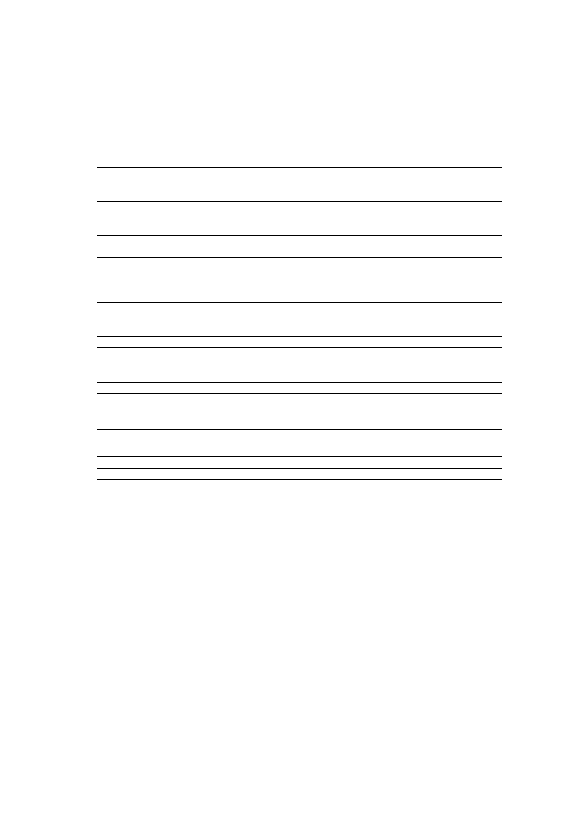
52
52
Machine
Heating
M12
Steam
M12
Electric
Other:
Distillation throughput (DIN 11916) max.
l/h (US gal/h)
80 (21.1)
80 (21.1)
Filter throughput
l/h (US gal/h)
4000 (1056)
4000 (1056)
Filter surface, economy filter 1
m2 (ft2)
2.4 (25.8)
2.4 (25.8)
Filter surface, economy filter 2
m2 (ft2)
2.4 (25.8)
2.4 (25.8)
Weight without solvent: Slimline
Crossline
kg(lbs)
kg(lbs)
1055(2326)
1155(2547)
1100(2326)
1155(2547)
Weight with solvent: Slimline
Crossline
kg(lbs)
kg(lbs)
1224(2699)
1324(2919)
1224(2699)
1324(2919)
Floor space: Slimline
Crossline
m2(ft2)
m2(ft2)
2.3(24.8)
2.5(26.9)
2.3(24.8)
2.5(26.9)
Floor surface: ** Slimline
Crossline
m2(ft2)
m2(ft2)
1.3(14)
1.3(14)
1.3(14)
1.3(14)
Cage centrifugal force
N(lb)
8500(1910)
8500(1910)
Floor load, stat. and dyn: Slimline
Crossline
N/m2 (lbs/ft2)
N/m2 (lbs/ft2)
15800(330)
16600(346)
15800(330)
16600(346)
Noise level
dB (A)
60
60
Heat balance: *
Heat to dissipate
via cooling water ***:
kJ/cycle
24800
24800
Heat dissipated to the surroundings:
kJ/cycle
5100
5100
9 Technical Specifications 9
* Values apply to a standard 2-bath load, 1st bath low level for distillation at
cooling water inlet temperature + 12 °C (53.6 °F), steam supply 4 – 5 bar (58.0 – 72.5 psi)
overpressure saturated steam, ambient temperature +5 °C to + 40 °C (5 to 104 °F)
** For portion of the floor surface for force transmission, see Installation Instructions, Point. 5.3.1
*** Refers to water without additives
Subject to change!
All values were taken under testing conditions with HC and can deviate in practice! With silicones
(e.g. GreenEarth) drying times will be extended by up to 10 minutes.
M12-M15-M18
Page 61

53
53
Machine
Heating
M15
Steam
M15
Electric
Filling quantity
kg (lb)
15 (33.1)
15 (33.1)
Cage volume
l (US gal)
300 (79.2)
300 (79.2)
Cage diameter
mm (in)
820 (32.3)
820 (32.3)
Cage depth
mm (in)
570 (22.4)
570 (22.4)
Load diameter
mm (in)
400 (15.7)
400 (15.7)
Cleaning speed/drying speed
RPM
40
40
Spinning speed
RPM
600
600
Max. g-factor 165
165
Low level
l (US gal)
35 (9.2)
35 (9.2)
High level
l (US gal)
75 (19.8)
75 (19.8)
Operating load (max. at 400 V, 50 Hz)
Without distillation
kW
7
16
With distillation
kW
8
27
Connected loads:
Compressor capacity
kW
4.0
4.0
Fan capacity HLL /NLL
kW
2.5 /1.85
2.5 /1.85
Solvent pump capacity
kW
1.1
1.1
Cage drive capacity
kW
3.7
3.7
Filter drive capacity
kW
0.55
0.55
Vacuum pump capacity
kW
0.37
0.37
Steam generator capacity Distill. /drying
kW
-
10 /8.5
Dimensions:
Machine:
Width: Slimline
Crossline
mm(in)
mm(in)
1080(42.5)
1840(77.4)
1080(42.5)
1840(77.4)
Depth: Slimline
Crossline
mm(in)
mm(in)
2165(86.0)
1406(55.3)
2165(86.0)
1406(55.3)
Height incl. trough
mm(in)
2257(89.0)
2257(89.0)
Height incl. trough without fan motor
mm(in)
1995(78.5)
1995(78.5)
Floor space: Slimline
Crossline
m2(ft2)
m2(ft2)
2.3(24.8)
2.5(26.9)
2.3(24.8)
2.5(26.9)
Filling volumes:
Tank I filling
l/ US gal
145 (38.3)
145 (38.3)
Tank II filling
l/ US gal
95 25.1)
95 (25.1)
Tank III filling
l/ US gal
90 (23.7)
90 (23.7)
Economy filter 1
l/ US gal
40 (10.6)
40 (10.6)
Economy filter 2
l/ US gal
40 (10.6)
40 (10.6)
Distillation filling
l/ US gal
120 (31.7)
120 (31.7)
Cartridge filter
l/ US gal
15 (4)
15 (4)
Jumbo Cartridge Filter
l /US gal
40 (10.5)
40 (10.5)
The dimensions given may differ if special options are used
9 Technical Specifications 9
M12-M15-M18
Page 62
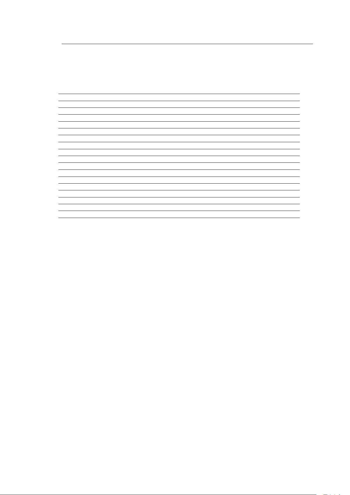
54
54
Machine
Heating
M15
Steam
M15
Electric
Consumption for drying:
Drying time incl. reduction
min.
29
31
Electric energy drying
kWh
2.3
6.7
Saturated steam drying
kg (lb)
5.6 (12.3)
-
Cooling water drying (12 °C/53.6 °F)
l (US gal)
90 (23.7)
90 (23.7)
Consumption for distillation(1x at low level):
Electric energy distillation
kWh
0.45
4.2
Saturated steam distillation
kg (lb)
8.4 (18.5)
-
Cooling water for distillation (12 °C/53.6 °F)
l (US gal)
130 (34.3)
130 (34.3)
Consumption per cycle: *
Electric energy, total
kWh
3.25
11.4
Saturated steam, total
kg (lb)
14 (30.8)
-
Cooling water, total (12 °C(53.6°F)
l (US gal)
220 (58.1)
220 (58.1)
Compressed air (6 bar/87 psi)
l (US gal)
6 (1.6)
6 (1.6)
9 Technical Specifications 9
M12-M15-M18
Page 63
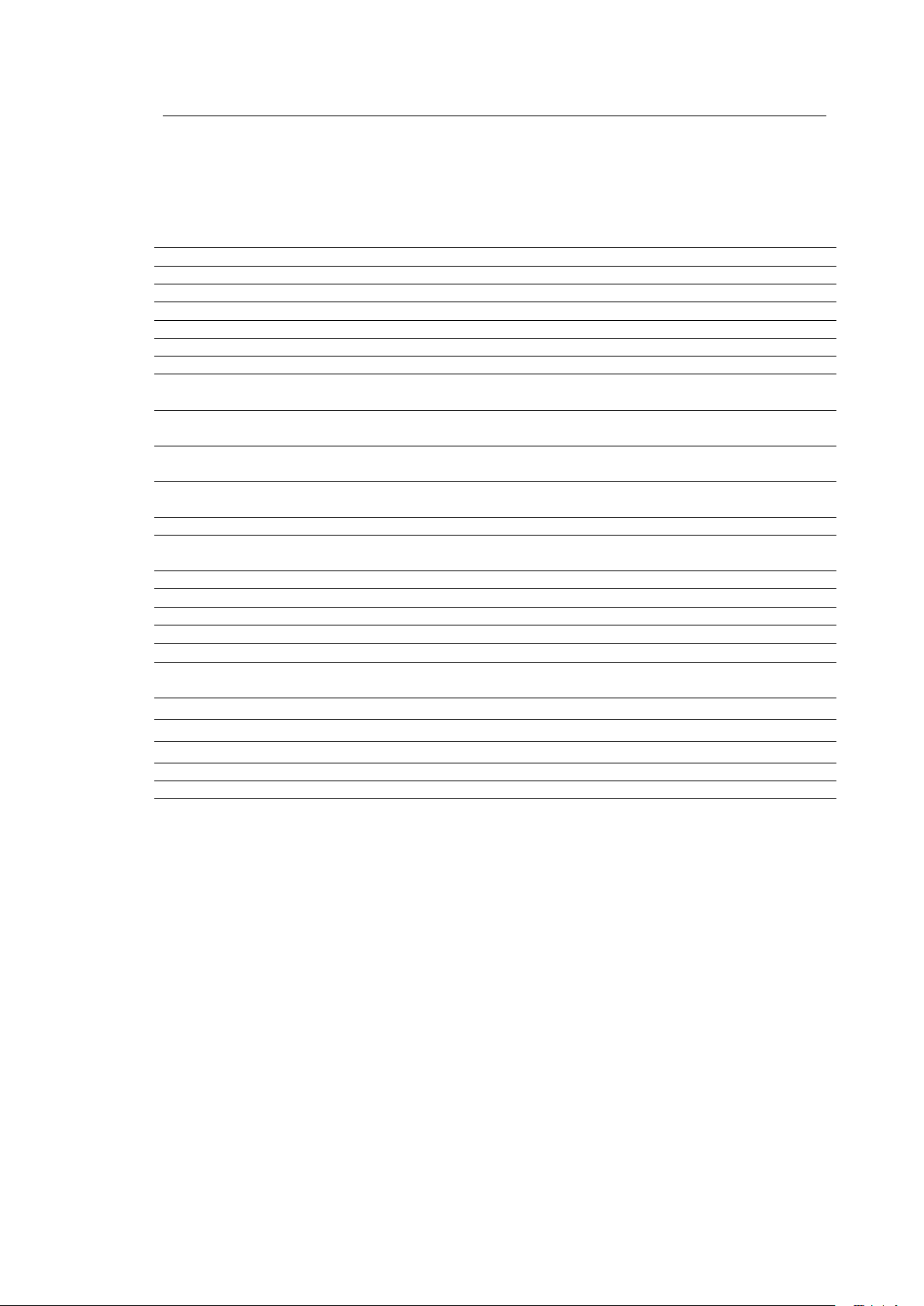
55
55
Machine
Heating
M15
Steam
M15
Electric
Other:
Distillation throughput (DIN 11916) max.
l/h (US gal/h)
80 (21.1)
80 (21.1)
Filter throughput
l/h (US gal/h)
4000 (1056)
4000 (1056)
Filter surface, economy filter 1
m2 (ft2)
2.4 (25.8)
2.4 (25.8)
Filter surface, economy filter 2
m2 (ft2)
2.4 (25.8)
2.4 (25.8)
Weight without solvent: Slimline
Crossline
kg(lb)
kg(lb)
1155(2546)
1255(2767)
1155(2546)
1255(2767)
Weight with solvent: Slimline
Crossline
kg(lb)
kg(lb)
1355(2987)
1455(3208)
1355(2987)
1455(3208)
Floor space: Slimline
Crossline
m2(ft2)
m2(ft2)
2.3(24.8)
2.5(26.9)
2.3(24.8)
2.5(26.9)
Floor surface: ** Slimline
Crossline
m2(ft2)
m2(ft2)
1.41(15.2)
1.41(15.2)
1.41(15.2)
1.41(15.2)
Cage centrifugal force
N(lb)
10700(2405)
10700(2405)
Floor load, stat. and dyn: Slimline
Crossline
N/m2 (lbs/ft2)
N/m2 (lbs/ft2)
17000(355)
17700(369)
17000(355)
17700(369)
Noise level
dB (A)
60
60
Heat balance: *
Heat to dissipate
via cooling water ***:
kJ/cycle
30400
30400
Heat dissipated to the surroundings *:
kJ/cycle
7100
7100
9 Technical Specifications 9
* Values apply to a standard 2-bath load, 1st bath low level for distillation at
cooling water inlet temperature + 12 °C (53.6 °F), steam supply 4 – 5 bar (58.0 - 72.5 psi)
overpressure saturated steam, ambient temperature +5 °C to + 40 °C (41 to 104 °F)
** For portion of the floor surface for force transmission, see Installation Instructions, Point 5.3.1
*** Refers to water without additives
Subject to change!
All values were taken under testing conditions with HC and can deviate in practice! With silicones
(e.g. GreenEarth) drying times will be extended by up to 10 minutes.
M12-M15-M18
Page 64
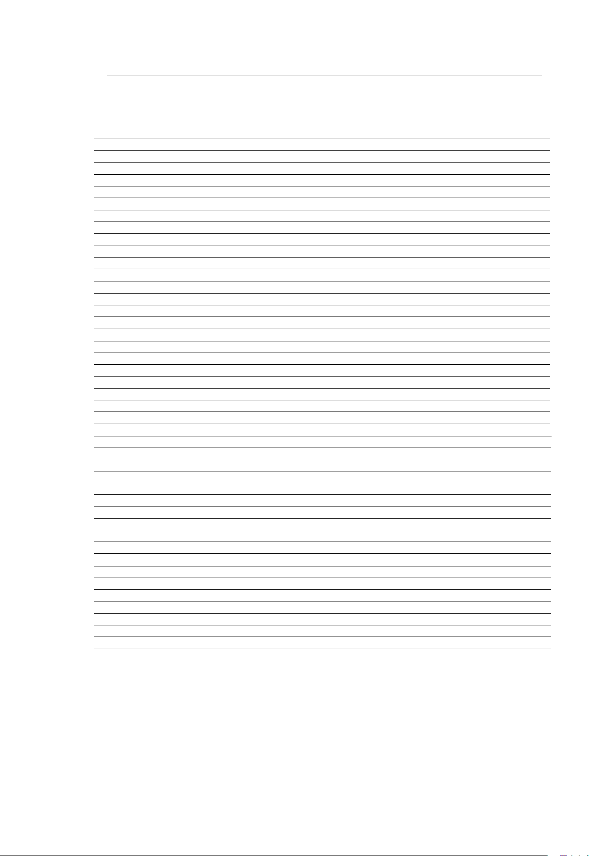
56
56
Machine
Heating
M18
Steam
M18
Electric
Filling quantity
kg (lb)
18 (39.7)
18 (39.7)
Cage volume
l/ US gal
360 (95.1)
360 (95.1)
Cage diameter
mm (in)
820 (32.3)
820 (32.3)
Cage depth
mm (in)
680 (26.7)
680 (26.7)
Load diameter
mm (in)
400 (15.7)
400 (15.7
Cleaning speed/drying speed
RPM
40
40
Spinning speed
RPM
600
600
Max. g-factor 165
165
Low level
l/ US gal
45 (11.9)
45 (11.9)
High level
l/ US gal
90 (23.7)
90 (23.7)
Operating load (max. at 400 V,50Hz)
Without distillation
kW
7
16
With distillation
kW
8
27
Connected loads:
Compressor capacity
kW
4.0
4.0
Fan capacity HLL /NLL
kW
2.5 /1.85
2.5 /1.85
Solvent pump capacity
kW
1.1
1.1
Cage drive capacity
kW
3.7
3.7
Filter drive capacity
kW
0.55
0.55
Vacuum pump capacity
kW
0.37
0.37
Steam generator capacity
kW
-
10 /8.5
Dimensions:
Machine:
Width: Slimline
Crossline
mm(in)
mm(in)
1080(42.5)
1840(77.4)
1080(42.5)
1840(77.4)
Depth: Slimline
Crossline
mm(in)
mm(in)
2275(89.5)
1540(60.6)
2275(89.5)
1540(60.6)
Height incl. trough
mm(in)
2257(89.0)
2257(89.0)
Height incl. trough without fan motor
mm(in)
1995(78.5)
1995(78.5)
Floor space: Slimline
Crossline
m2(ft2)
m2(ft2)
2.4(25.8)
2.7(29.0)
2.4(25.8)
2.7(29.0)
Filling volumes:
Tank I filling
l/ US gal
170 (44.9)
170 (44.9)
Tank II filling
l/ US gal
110 (29)
110 (29)
Tank III filling
l/ US gal
90 (23.7)
90 (23.7)
Economy filter 1
l/ US gal
40 (10.6)
40 (10.6)
Economy filter 2
l/ US gal
40 (10.6)
40 (10.6)
Distillation filling
l/ US gal
120 (31.7)
120 (31.7)
Cartridge filter
l/ US gal
15 (6.6)
15 (6.6)
Jumbo Cartridge Filter
l /US gal
40 (10.5)
40 (10.5)
The dimensions given may differ if special options are used
9 Technical Specifications 9
M12-M15-M18
Page 65

57
57
Machine
Heating
M18
Steam
M18
Electric
Consumption for drying:
Drying time incl. reduction
min.
34
36
Electric energy drying
kWh
2.5
8
Saturated steam drying
kg (lbs)
6.7 (14.7)
-
Cooling water drying (12 °C/53.6 °F)
l (US gal)
100 (26.4)
100 (26.4)
Consumption for distillation(1x at low
level):
Electric energy distillation
kWh
0.65
5.0
Saturated steam distillation
kg (lb)
10.3 (22.7)
-
Cooling water for distillation (12 °C/53.6 °F)
l (US gal)
160 (42.2)
160 (42.2)
Consumption per cycle: *
Electric energy, total
kWh
3.65
13.5
Saturated steam, total
kg (lb)
17.0 (37.5)
-
Cooling water, total (12 °C(53.6°F)
l (US gal)
260 (68.6)
260 (68.6)
Compressed air (6 bar/87 psi)
l (US gal)
6 (1.6)
6 (1.6)
9 Technical Specifications 9
M12-M15-M18
Page 66
58
58
Machine
Heating
M18
Steam
M18
Electric
Other:
Distillation throughput (DIN 11916) max.
l/h (US gal/h)
80 (21.1)
80 (21.1)
Filter throughput
l/h (US gal/h)
4000 (1056)
4000 (1056)
Filter surface, economy filter 1
m2 (ft2)
2.4 (25.8)
2.4 (25.8)
Filter surface, economy filter 2
m2 (ft2)
2.4 (25.8)
2.4 (25.8)
Weight without solvent: Slimline
Crossline
kg(lb)
kg(lb)
1325(2921)
1355(2987)
1325(2921)
1355(2987)
Weight with solvent: Slimline
Crossline
kg(lb)
kg(lb)
1556(3430)
1586(3497)
1556(3430)
1586(3497)
Floor space: Slimline
Crossline
m2(ft2)
m2(ft2)
2.4(25.8)
2.7(29.0)
2.4(25.8)
2.7(29.0)
Floor surface: ** Slimline
Crossline
m2(ft2)
m2(ft2)
1.53(16.4)
1.53(16.4)
1.53(16.4)
1.53(16.4)
Cage centrifugal force
N(lb)
12800(2877)
12800(2877)
Floor load, stat. and dyn: Slimline
Crossline
N/m2 (lbs/ft2)
N/m2 (lbs/ft2)
18300(382)
18500(386)
18300(382)
18500(386)
Noise level
dB (A)
60
60
Heat balance: *
Heat to dissipate
via cooling water ***:
kJ/cycle
35900
35900
Heat dissipated to the surroundings:
kJ/cycle
9000
9000
9 Technical Specifications 9
* Values apply to a standard 2-bath load, 1st bath low level for distillation at
cooling water inlet temperature + 12 °C (53.6 °F), steam supply 4 – 5 bar (58.0 - 72.5 psi)
overpressure saturated steam, ambient temperature +5 °C to + 40 °C (5 to 104 °F)
** For portion of the floor surface for force transmission, see Installation Instructions, Point. 5.3.1
*** Refers to water without additives
Subject to change!
All values were taken under testing conditions with HC and can deviate in practice! With silicones
(e.g. GreenEarth) drying times will be extended by up to 10 minutes.
M12-M15-M18
Page 67
59
59
10 Settings and Optimum Operating Values
10
Machine
M12 M15
Basic value:
Steam pressure (saturated steam)
bar(psi)
4–5(58–72.5)
4–5(58 – 72.5)
Steam temperature (max. permitted)
°C(°F)
150(302)
150(302)
Cooling water pressure
bar(psi)
2-4(29-58)
2-4(29-58)
Low cooling water level switch
bar (psi)
2 (29)
2 (29)
Cooling water temperature, max.
°C(°F)
25(77)
25(77)
Compressed air
bar(psi)
6(87)
6(87)
Low air pressure switch (if present)
bar (psi)
4 (58)
4 (58)
Cage speeds:
Cleaning / drying
RPM
35
35
Spinning
RPM
400 /600
400/600
Reversing cycle (cleaning)
sec.
10/1/10
10/1/10
Low level
l(US gal)
30(7.9)
35(9.2)
High level
l(US gal)
60(15.8)
75(19.8)
Pump pressure (max.)
bar(psi)
1.5(22)
1.5(22)
Filter surface, economy filter
m2 (ft2)
2.4(34.8)
2.4(34.8)
Tank I: optimum filling volume (high level)
l(US gal)
60(15.8)
75(19.8)
Tank III: optimum filling volume
l(US gal)
60(15.8)
75(19.8)
Detergent solution cooler:
Detergent solution thermal sensor:
Detergent solution cooler ON
°C(°F) 40(104)
40(104)
Alarm value
°C (°F)
45 (113)
45 (113)
Refrigeration technology:
Filling capacity, cooling agent R 404A
kg(lb)
4.6(10.1)
4.6(10.1)
Expansion valve:
Nozzle size: solvent cooling
no.
03
03
Drying /reduction
no.
01
01
High pressure control switch ON
bar(psi)
21(304)
21(304)
High pressure control switch OFF
bar(psi)
25(362)
25(362)
Drying:
Cooling water regulator setting:
Adjust 4 – 6 min. after start of drying
bar(psi)
18(261)
18(261)
Temp. sensor, cage entry (gentle drying)*
°C(°F)
75(167)
75(167)
Temp. sensor after cooler:
Alarm value, 1
°C(°F)
30(86)
30(86)
Alarm value, 2
°C(°F)
35(95)
35(95)
Safety temperature limiter after cooler:*
°C(°F)
45 (113)
45 (113)
Safety temperature limiter cage inlet:*
°C(°F)
100 (212)
100 (212)
* at flash point >55°C (131°F)
M12-M15-M18
Page 68
60
60
Machine
M12 M15
Distillation
Cooling water regulator condenser
°C
(°F)
45
(113)
45
(113)
Thermal sensor:
Cycle distillation OFF
°C
(°F)
133
(271)
133
(271)
Still stripping OFF
°C
(°F)
138
(280)
138
(280)
Residue draining
°C
(°F)
55
(131)
55
(131)
Thermal sensor, distilled solvent *
°C
(°F)
45
(113)
45
(113)
Restrictor in steam feeder
mm
(in)
6
(.24) 6 (.24)
Vacuum pressure control
kPa
minus 75
minus 75
Temperature sensor heater element (electric)
°C(°F)
230 (446)
230 (446)
10 Settings and Optimum Operating Values 10
* at flash point >55°C (131 °F)
M12-M15-M18
Page 69
61
61
Machine
M18
Basic value:
Steam pressure (saturated steam)
bar(psi)
4–5(58–72.5)
Steam temperature (max. permitted)
°C(°F)
150(302)
Cooling water pressure
bar(psi)
2-4(29-58)
Low cooling water level switch
bar (psi)
2 (29)
Cooling water temperature, max.
°C(°F)
25(77)
Compressed air
bar(psi)
6(87)
Low air pressure switch (if present)
bar (psi)
4 (58)
Cage speeds:
Cleaning / drying
RPM
35
Spinning
RPM
400 /600
Reversing cycle (cleaning)
sec.
10/1/10
Low level
l(US gal)
45(11.9)
High level
l(US gal)
90(23.7)
Pump pressure (max.)
bar(psi)
1.5(22)
Filter surface, economy filter
m2 (ft2)
2.4(34.8)
Tank I: optimum filling volume (high level)
l(US gal)
90(23.7)
Tank III: optimum filling volume
l(US gal)
90(23.7)
Detergent solution cooler:
Detergent solution thermal sensor:
Detergent solution cooler ON
°C(°F) 40(104)
Alarm value
°C (°F)
45 (113)
Refrigeration technology:
Filling capacity, cooling agent R 404A
kg(lb)
4.6(10.1)
Expansion valve:
Nozzle size: solvent cooling
no.
03
Drying /reduction
no.
01
High pressure control switch ON
bar(psi)
21(304)
High pressure control switch OFF
bar(psi)
25(362)
Drying:
Cooling water regulator setting:
Adjust 4 – 6 min. after start of drying
bar(psi)
18(261)
Temp. sensor, cage entry (gentle drying)*
°C(°F)
75(167)
Temp. sensor after cooler:
Alarm value, 1
°C(°F)
30(86)
Alarm value, 2
°C(°F)
35(95)
Safety temperature limiter after cooler:*
°C(°F)
45 (113)
Safety temperature limiter cage inlet:*
°C(°F)
100 (212)
10 Settings and Optimum Operating Values 10
* at flash point >55°C (131 °F)
M12-M15-M18
Page 70

62
62
Machine
M18
Distillation
Cooling water regulator condenser
°C
(°F)
45
(113)
Thermal sensor:
Cycle distillation OFF
°C
(°F)
133
(271)
Still stripping OFF
°C
(°F)
138
(280)
Residue draining
°C
(°F)
55
(131)
Thermal sensor, distilled solvent *
°C
(°F)
45
(113)
Restrictor in steam feeder
mm
(in)
6
(.24)
Vacuum pressure control
kPa
minus 75
Temp. sensor heater element (el.)
°C(°F)
230 (446)
10 Settings and Optimum Operating Values 10
* at flash point >55°C (131 °F)
M12-M15-M18
Page 71
63
63
11 Safety Remarks Located on the Machine
11
Kontaktwasser kann geringe Spuren von Lösemittel enthalten.
Vorschriftsmäßig entsorgen!
Contact water may contain small quantities of solvent.
Please dispose of according to the regulations in your country!
L’eau de contact peut contenir une petite quantité de solvant.
Evacuer l’eau de contact conformément à la réglementation.
SN 708073
Nadelfänger täglich bzw. bei Bedarf öfter reinigen
(Nur bei ausgeschalteter Maschine und nach beendeter Trocknungsphase).
Clean button trap if necessary but at least once a day
(only if machine is switched off and the drying phase has been finished).
Nettoyer le filtre à épingle tous les jours et si nécessaire plus souvent
(seulement hors fonctionement de la machine et après une opération de séchage).
SN 708074
Reinigen der Destillation nur bei
- ausgeschalteter Maschine und
- kalter Destillierblase durchführen
Clean still only if
- machine is switched off and
- distillation is cold
Nettoyer l’alambic seulement si:
-La machine est hors de fonctionement
- Le distillateur est revenu à températur ambiante
SN 708075
Gemäß EN ISO 8230 befinden sich an der Maschine nachfolgende
Sicherheitshinweise:
In accordance with EN ISO 8230 the machine is fitted with
safety hints as given below:
Conforme à EN ISO 8230 les indications de sécurité suivantes se trovent
à la machine:
M12-M15-M18
Page 72
64
64
Vorsicht!
Heiße Oberflächen
Attention!
Hot surfaces
Attention!
Surface chaude
SN 708076
Zulässige Füllmenge
Max. filling capacity
Capacité admissible
SN 708086
Filter täglich bzw. bei Bedarf öfter reinigen
(nur bei ausgeschalteter Maschine und nach beendeter Trocknungsphase)
Clean lint filter if necessary but at least once a day
(only if machine is switched off and the drying phase has been finished.)
Nettoyer le filtre tous les jours et si nécessaire plus souvent
(seulement hors fonctionement de la machine et après une opération de séchage).
SN 708087
Filter und Wasserabscheider dürfen manuell
nur bei leerer Destillation abgelassen werden.
Filter and water separator must only be drained manually
if the distillation is empty.
La vidange manuelle du filtre à solvant et du séparateur d’eau
est seulement permise quand le distillateur est vide.
SN 708077
12 kg /30 lbs
Zulässige Füllmenge
Max. filling capacity
Capacité admissible
SN 800195
15 kg /35 lbs
Zulässige Füllmenge
Max. filling capacity
Capacité admissible
SN 800196
18 kg /40 lbs
Zulässige Füllmenge
Max. filling capacity
Capacité admissible
SN 800197
11 Safety Remarks Located on the Machine 11
M12-M15-M18
Page 73
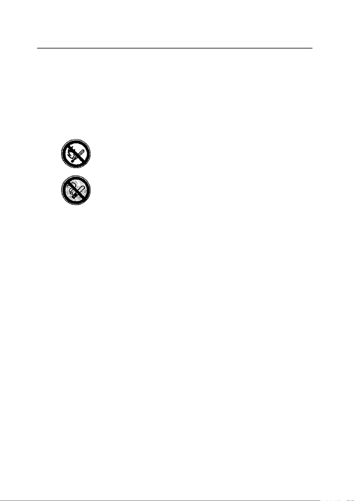
65
65
For cleaning machines that operate with combustible solvent
Hazardous to humans and the environment:
Risk of fire or explosion if any contact with open flames, embers or sparks
Damages the skin, risk of eczema formation
Serious damage to the lungs is possible if vapor is inhaled
Safety precautions:
No source of fire near the solvent, absolutely no smoking
Avoid skin contact, use protective gloves if possible
No direct contact with the solvent
Use protective skin cream regularly
Do not eat or drink in the work area
What to do in case of fire:
In case of fire, extinguish with a carbon dioxide or foam fire extinguisher
If you spill solvent, use a suitable bonding agent
First aid:
Immediately remove clothing wet with solvent
If you inhale concentrated vapor, go out into the fresh air immediately
If you get solvent in your eyes, rinse with water and contact a physician immediately
Disposal:
When stored, the solvent must be kept in closed containers and must be disposed of by experts
only.
11 Safety Remarks Located on the Machine 11
M12-M15-M18
Page 74
66
BÖWE Textile Cleaning GmbH
Lochmatt 1A, 77880 Sasbach / Germany
T: +49 (0)7841 - 6002 - 200
F: +49 (0)7841 - 6002 - 230
E-Mail: [email protected]
Internet: www.bowe-germany.de
 Loading...