

Page 1
TORSIONAL ULTRASONIC SCALPEL
Quick reference guide
Page 2

2
IMPORTANT NOTICE
This quick reference guide is a brief summary of the operating instructions, it is not a substitute for the User Manual. For full
instructions on the operation of this equipment please refer to the LOTUS Series 4 User Manual.
CONTENTS
1. Fundamental principles
1.1 Technology
1.2 Effects on tissue
1.3 Applications
2. Set-up
2.1 System overview
2.2 Set up of handpiece and transducer
2.3 Generator
2.4 Explanation of symbols
3. Cleaning in the sterile field
4. Device compatibility
Page 3
3
LOTUS torsional technology
1.1 | TECHNOLOGY
1. FUNDAMENTAL PRINCIPLES | 2. SET-UP | 3. CLEANING IN THE STERILE FIELD | 4. DEVICE COMPATIBILITY
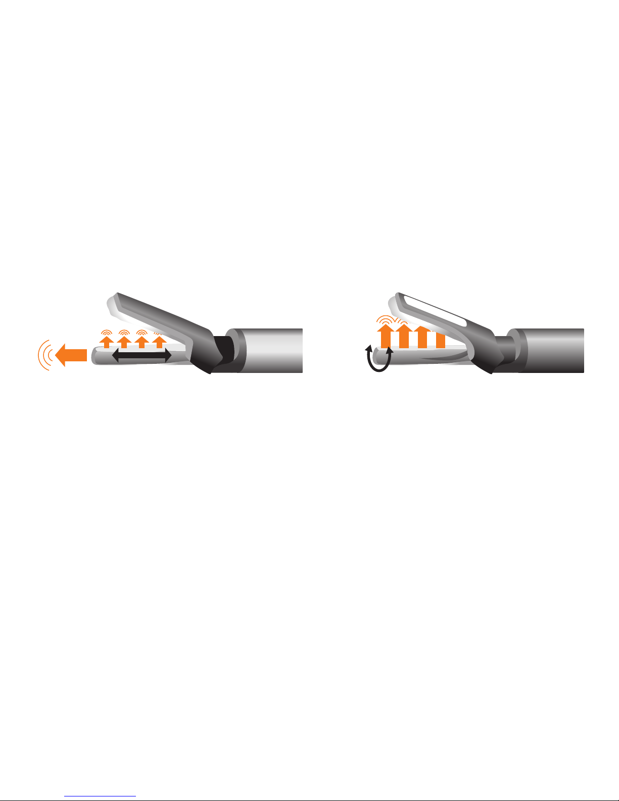
Conventional ultrasonic instruments
Energy is fed in the axial direction through the tip of the
instrument. This leads to high stray energy dissipation at the
tip of the instrument. As a result, unintentional distal drilling
into tissue is a common cause of concern.
LOTUS torsional ultrasonic scalpel
The LOTUS system’s energy is perpendicular (90 degrees)
to the axis of the blade. This coupled with the blade geometry
focuses the energy into the jaw area. LOTUS also offers enhanced
safety by reducing the risk of inadvertent damage from stray
distal energy.
Schematic illustrationSchematic illustration
Page 4
4
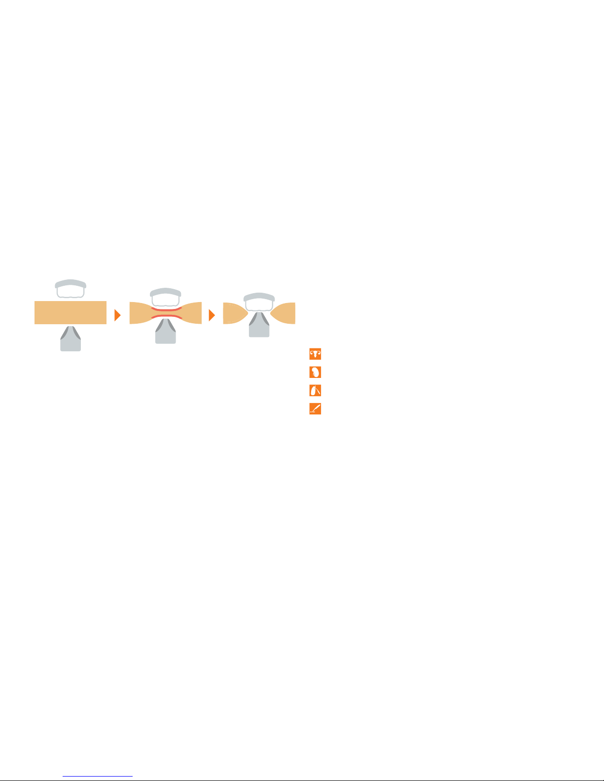
LOTUS can be used for haemostatic dissection of all types of
soft tissues: large pedicles, vascular structures and even tough
tissues such as the cervix or scar tissue.
Specialist surgical areas:
The cutting speed of the LOTUS ultrasonic scalpel is directly
related to the pressure on the trigger.
The clear tactile feedback enables precise cutting control by
the surgeon.
Gynaecology
Urology
Thoracic surgery
General surgery
- Upper Gastro- Intestinal
- Colorectal
- HPB
- Bariatric Surgery
1.3 | APPLICATIONS1.2 | EFFECTS ON TISSUE
CutCoagulate / SealGrasp
1. FUNDAMENTAL PRINCIPLES | 2. SET-UP | 3. CLEANING IN THE STERILE FIELD | 4. DEVICE COMPATIBILITY
Page 5
5
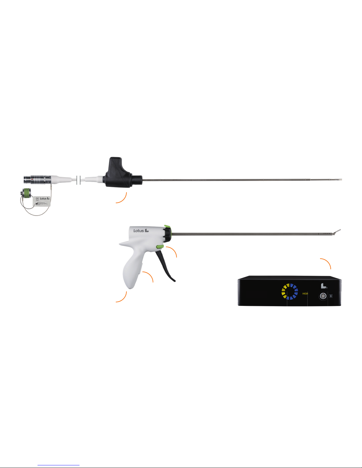
2.1 | SYSTEM OVERVIEW
Torsional transducer
Handpiece
Power select button
Activation button
LOTUS Series 4 generator
1. FUNDAMENTAL PRINCIPLES | 2. SET-UP | 3. CLEANING IN THE STERILE FIELD | 4. DEVICE COMPATIBILITY
Page 6
6
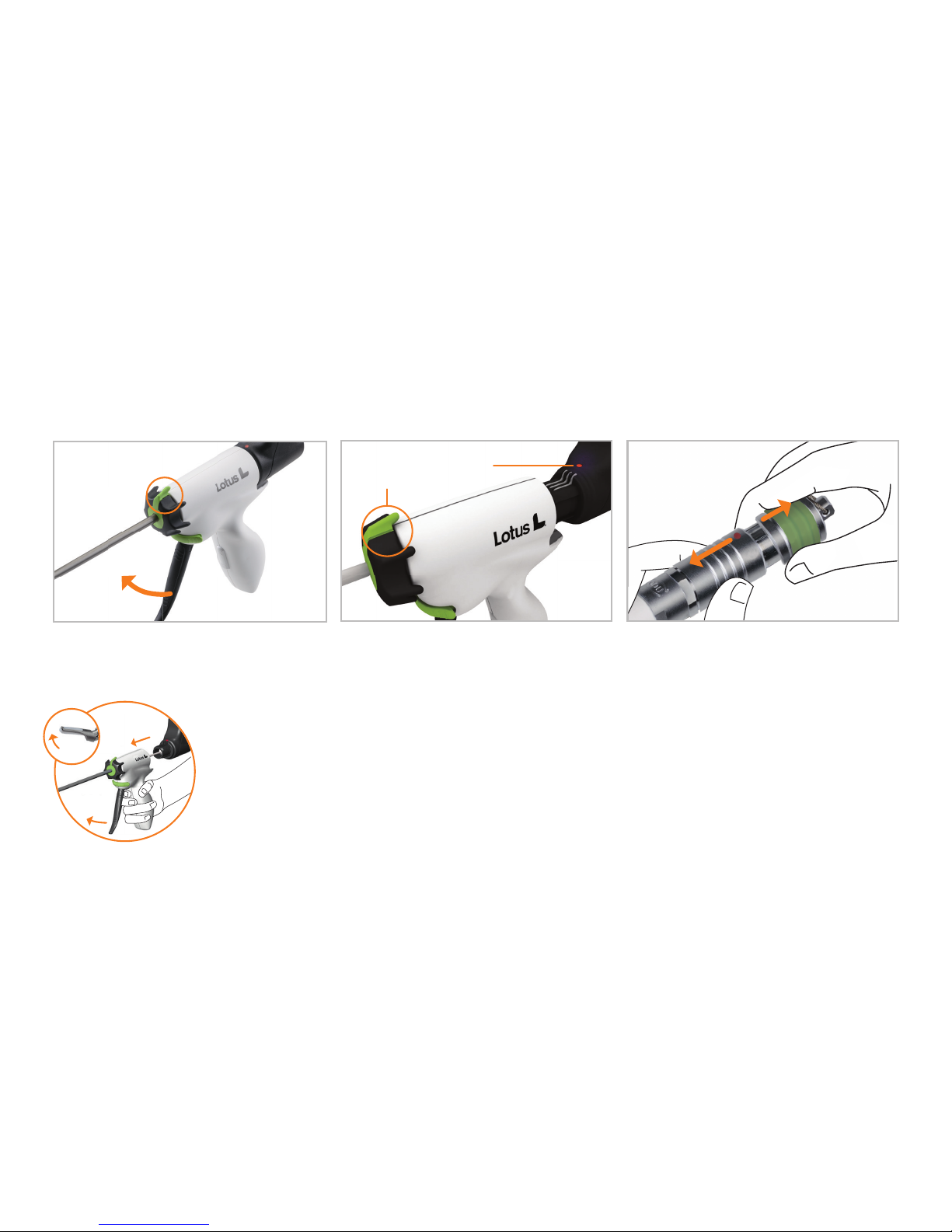
2.2 | SET-UP OF HANDPIECE AND TRANSDUCER
Rotate the coloured fin on the rotation
wheel to 12 o’clock.
Ensure the coloured dot on the
transducer is aligned with the coloured
fin of the rotation wheel.
Ensure that the jaw is in the open
position and then push the transducer
and handpiece together.
To remove the end cap, hold the ribbed
area of the connector cap between thumb
and forefinger and pull back the ribbed
sleeve of the cap. Do not remove the end
cap until it has been passed out of the
sterile field.
Align the red dot on the connector with
the red dot on the generator cable socket
and push together. To remove the
connector, pull back the ribbed sleeve of
the connector in the same way.
Coloured fin on
the rotation
wheel at
12 o’clock
Open jaw
Coloured dot on the transducer
is aligned with coloured fin
of the rotation wheel
1. FUNDAMENTAL PRINCIPLES | 2. SET-UP | 3. CLEANING IN THE STERILE FIELD | 4. DEVICE COMPATIBILITY
Open the jaw by
releasing the
spring loaded
trigger.
Page 7
7
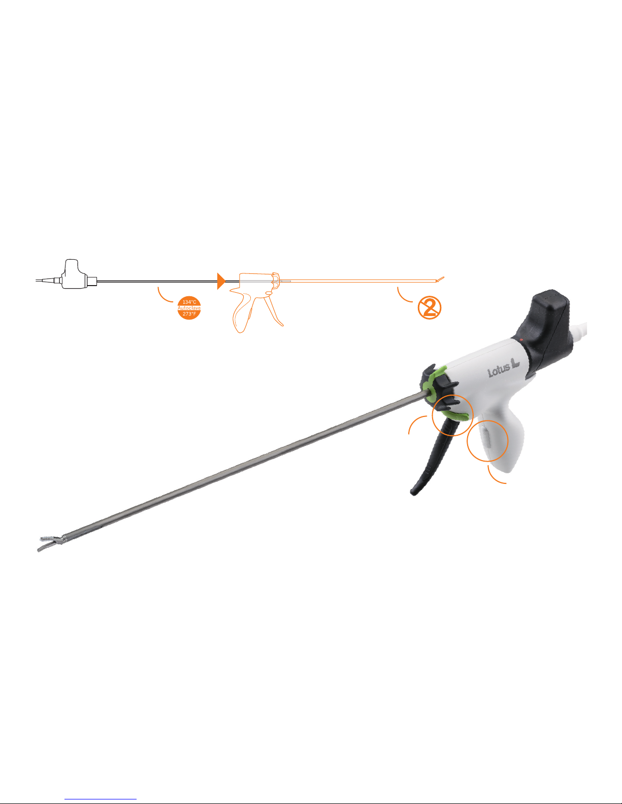
Power select button
Activation
button
1. FUNDAMENTAL PRINCIPLES | 2. SET-UP | 3. CLEANING IN THE STERILE FIELD | 4. DEVICE COMPATIBILITY
Handpiece
Simple plug and
play set-up
LOTUS torsional transducer
Tool-less instrument assembly
Page 8
8
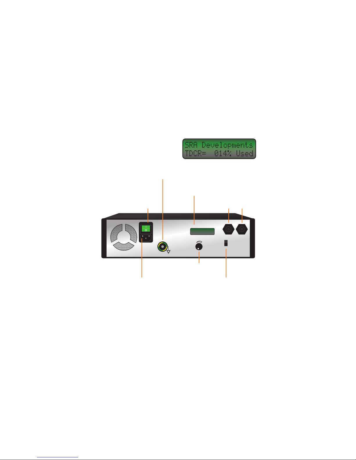
2.3 | GENERATOR
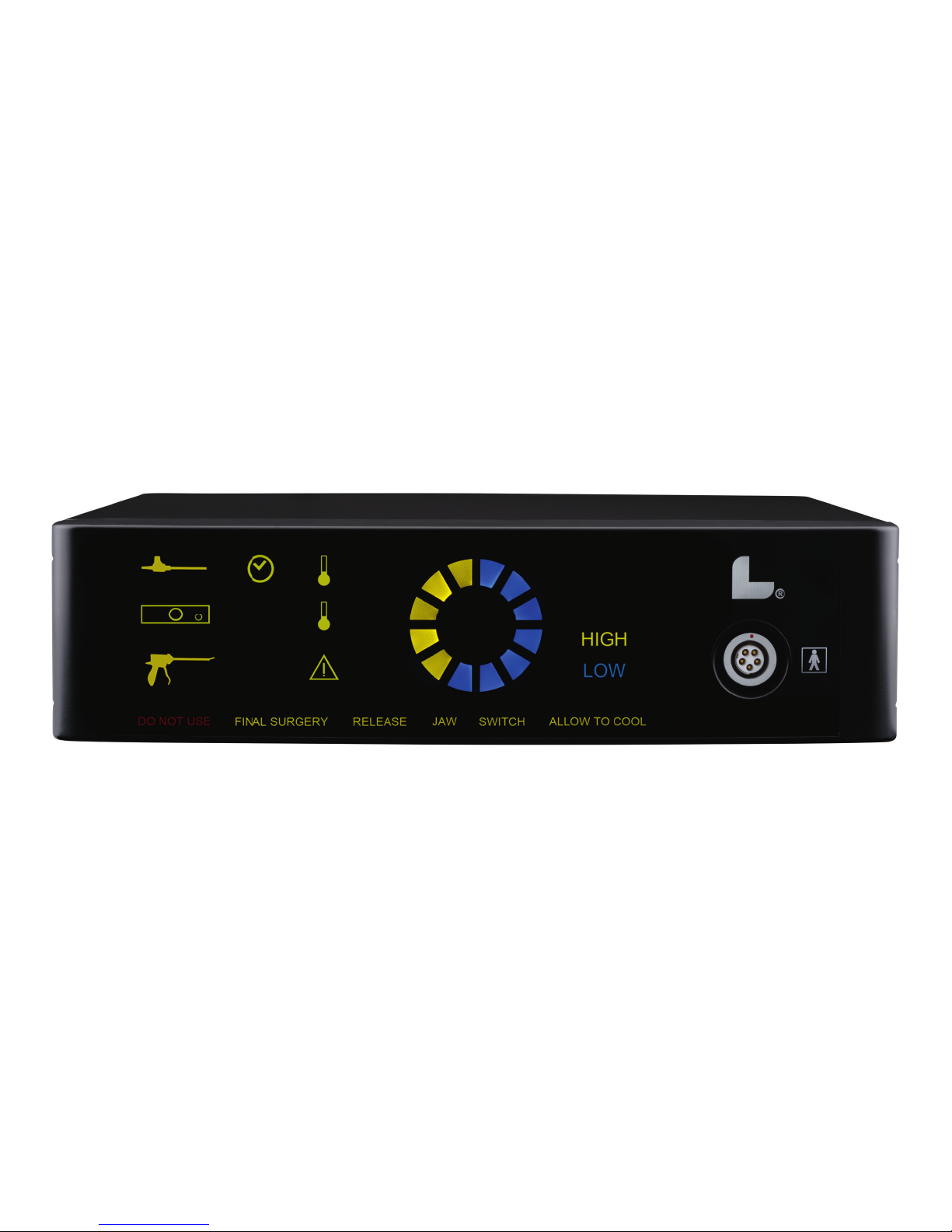
The switch on the rear of the unit allows you to alter the LOW
power setting. This enables you to switch between ULTRA
LOW and LOW power. you can still switch back to HIGH power
using the Power Select button
IEC Power socket
The mains power switch is located on the rear of the unit.
As soon as the generator is turned on, all the symbols on the
generator will briefly illuminate to ensure that the LED
displays are working.
The lifetime of the transducer is limited to 250 minutes. It is
stored within the instrument and can be read on the rear of
the unit when the transducer has been inserted.
Power switch
Equipotential connection
Volume control
Sockets for optional foot switch
LOW
ULTRA
LOW
LOW POWER
SELECTION
1. FUNDAMENTAL PRINCIPLES | 2. SET-UP | 3. CLEANING IN THE STERILE FIELD | 4. DEVICE COMPATIBILITY
Page 9
9
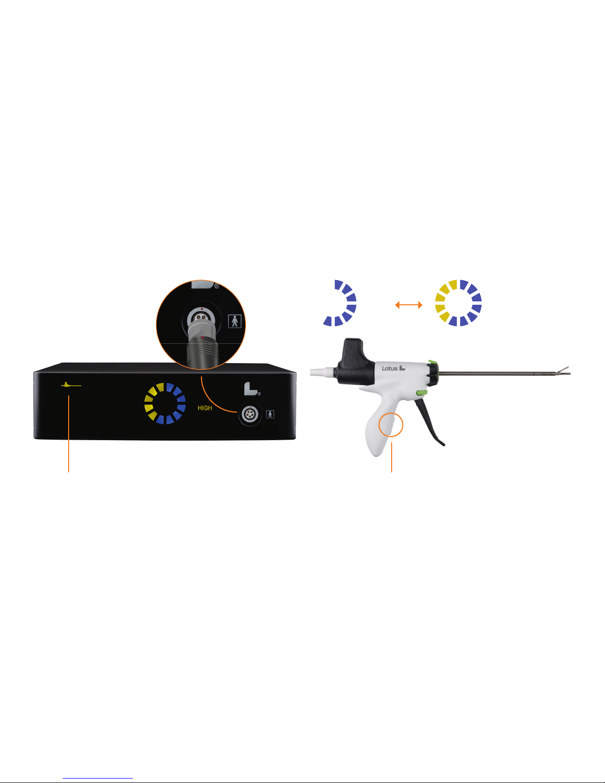
Power Select button
To start using the device, first press the Power Select button.
The system will be initialised on LOW power. To switch to
HIGH power press the Power Select button again.
HIGH
LOW
When the activation button is depressed, the transducer
symbol on the generator lights up.
To engage the cable, align
the coloured dots on the
connector and the generator and push to insert.
1. FUNDAMENTAL PRINCIPLES | 2. SET-UP | 3. CLEANING IN THE STERILE FIELD | 4. DEVICE COMPATIBILITY
Page 10
10
2.4 | EXPLANATION OF SYMBOLS
1. FUNDAMENTAL PRINCIPLES | 2. SET-UP | 3. CLEANING IN THE STERILE FIELD | 4. DEVICE COMPATIBILITY
Page 11
11
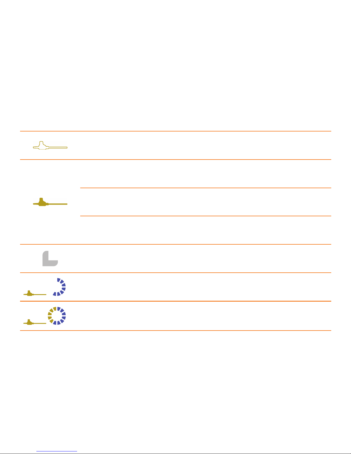
SYMBOLS DESCRIPTION OF SYMBOLS MEANING ACTION REQUIRED
Transducer symbol
not illuminated.
Transducer has reached the
end of its operating lifetime.
Transducer must be replaced.
Transducer symbol
lights up briefly.
Transducer has been recognised.
Transducer symbol is continually
illuminated.
Transducer must be serviced after
the operation.
Return the decontaminated transducer for servicing.
Transducer symbol lights up
when the activation button
is depressed.
Unit activated, instrument in use.
Only the “L” LED is illuminated.
Before initialisation the generator
is in standby mode.
Briefly press the Power Select
button to begin.
LOW
“LOW” illuminated.
The unit is switched to the LOW
power setting.
Switch between the HIGH and
LOW power setting using the
Power Select button.
HIGH
“HIGH” illuminated.
The unit is switched to the HIGH
power setting.
Switch between the HIGH and
LOW power setting using the
Power Select button.
1. FUNDAMENTAL PRINCIPLES | 2. SET-UP | 3. CLEANING IN THE STERILE FIELD | 4. DEVICE COMPATIBILITY
Page 12
12
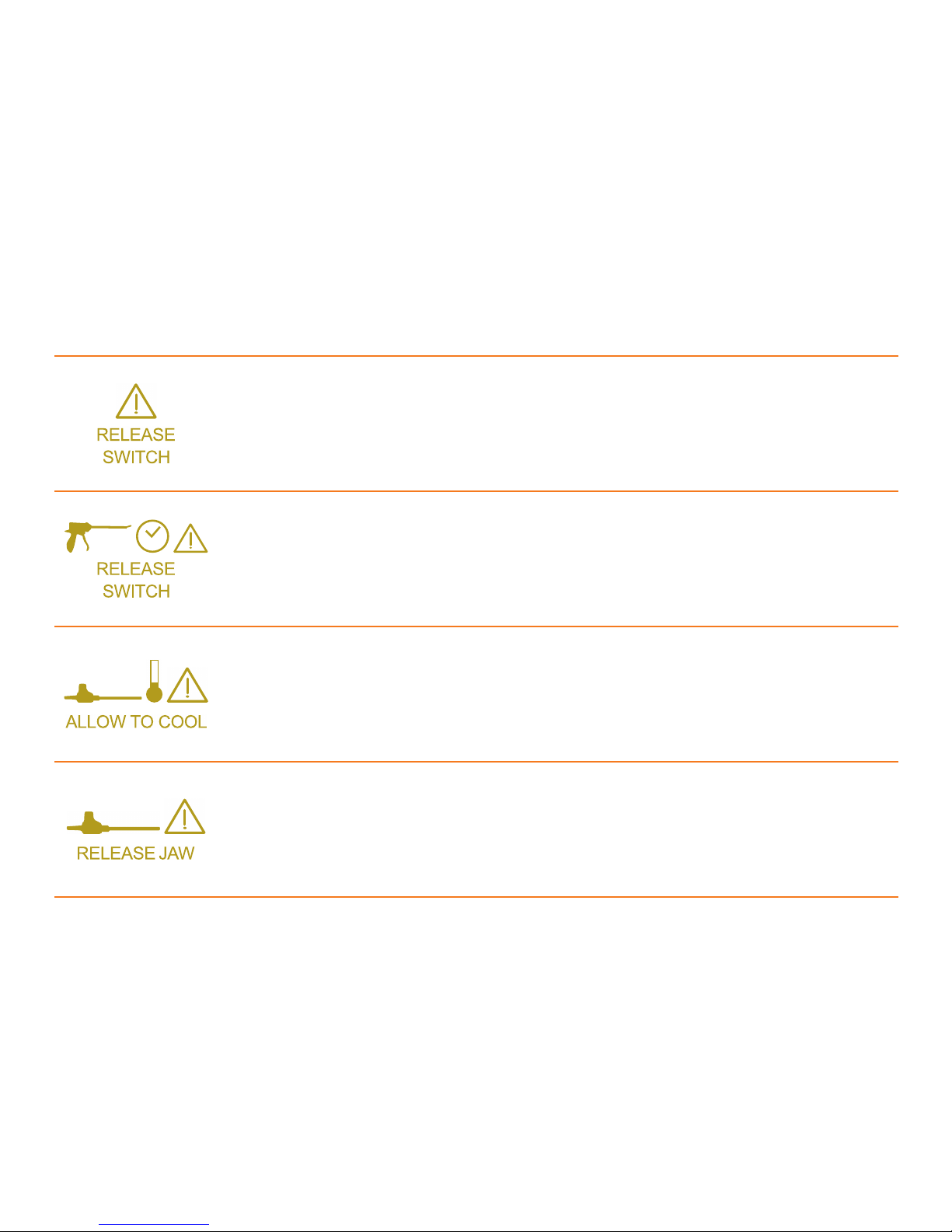
SYMBOLS DESCRIPTION OF SYMBOLS MEANING ACTION REQUIRED
RELEASE and SWITCH warning
symbols illuminated.
- Power Select button or activation
button is being pressed during
initialisation.
- Power Select button remains depressed after the power setting
has been changed.
Release the Power Select button.
The generator will automatically
restart.
RELEASE and SWITCH warning
symbols as well as Handpiece and
Clock symbols illuminated.
The handpiece has been used for
longer than 25 seconds in a single
activation. The unit has paused for
safety.
Release the activation button.
The generator will automatically
restart.
Warning, ALLOW TO COOL,
Thermometer and Transducer
symbols illuminated.
The transducer or the waveguide is
getting warm.
- Remove transducer from handpiece and wipe off using a damp
swab to cool instantly.
- Transducer may be defective or
damaged and must be replaced.
Warning symbol, RELEASE JAW
symbol and Transducer symbol
illuminated.
Handpiece being
gripped too tightly.
Release handpiece trigger and
activation button.
The generator will automatically
reset in 1–2 seconds.
1. FUNDAMENTAL PRINCIPLES | 2. SET-UP | 3. CLEANING IN THE STERILE FIELD | 4. DEVICE COMPATIBILITY
Page 13
13
1. FUNDAMENTAL PRINCIPLES | 2. SET-UP | 3. CLEANING IN THE STERILE FIELD | 4. DEVICE COMPATIBILITY
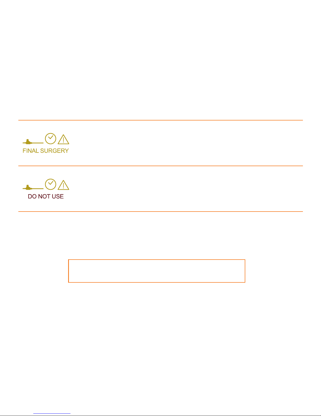
SYMBOLS DESCRIPTION OF SYMBOLS MEANING ACTION REQUIRED
Warning symbol, Clock symbol,
FINAL SURGERY and Transducer
symbol illuminated.
The transducer has reached more
than 98 % of its operating lifetime.
The operation in progress can be
completed.
After the transducer is unplugged
from the generator, it will be disabled and can no longer be used.
Warning symbol, Clock symbol,
DO NOT USE and Transducer
symbol illuminated.
After the “FINAL SURGERY”
symbol was illuminated, the
transducer was mistakenly
reapplied and connected. The
transducer can no longer be used.
Please replace the transducer.
CONTRAINDICATIONS AND WARNINGS:
For a full list of warnings, indications and contraindications for use, please refer
to the full User Manual, a copy of which was supplied with the equipment.
Page 14
14
3. | CLEANING IN THE STERILE FIELD
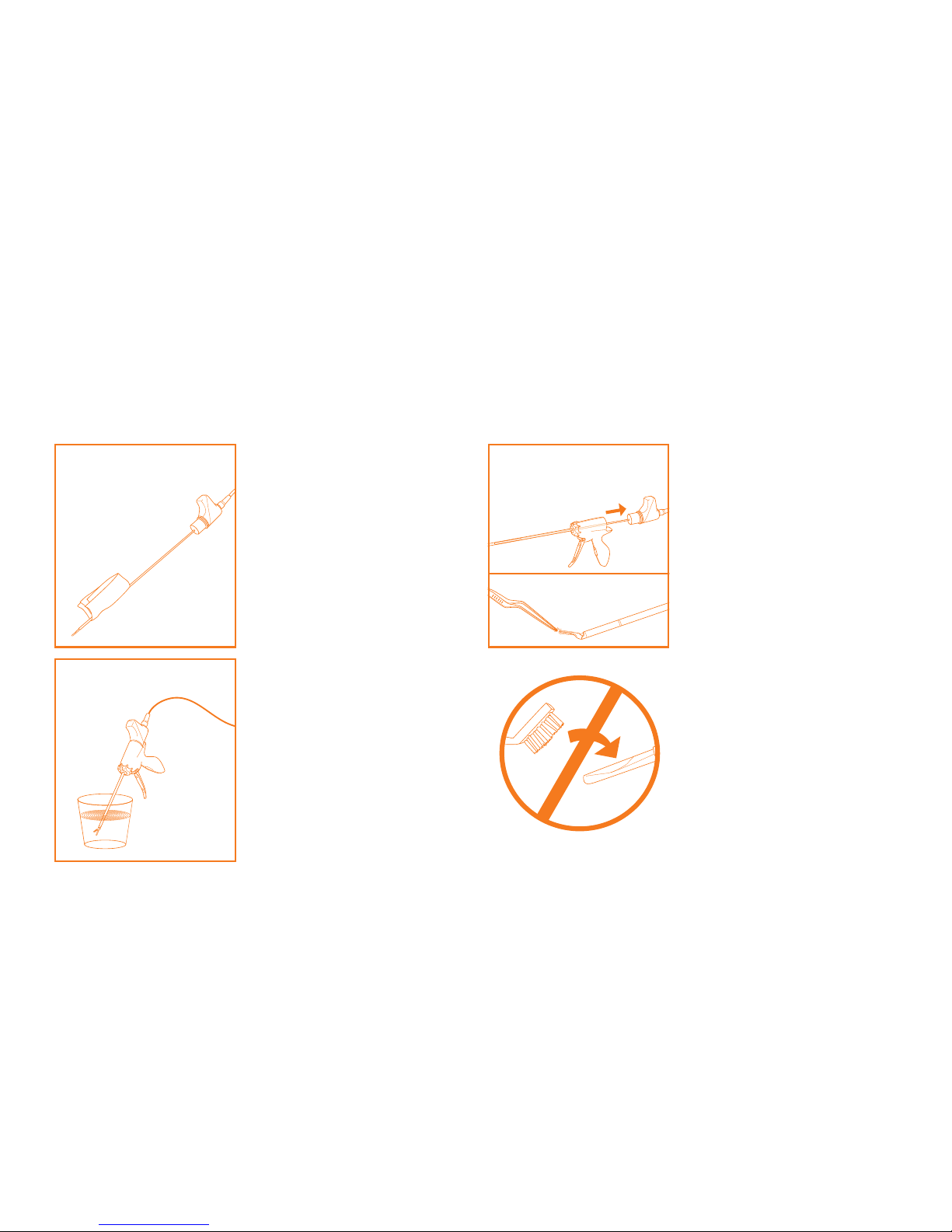
1. Mild debris
2. Heavy debris
3. Hardened debris
METAL
Remove the transducer from
the handpiece. Clean the
transducer’s waveguide with a
damp swab. Debris around the
handpiece jaw mechanism can
be removed using forceps or a
damp swab as required. Take
care not to damage the jaw of
the handpiece by using excess
force or bending it.
IMPORTANT: Avoid using
metal objects to clean debris
from the waveguide as this
may cause scratches and other
damage.
WE RECOMMEND AVOIDING
ALL METAL ON METAL
CONTACT WITH THE WAVEGUIDE INCLUDING CUTTING
CLIPS AND TOUCHING
GRASPERS ETC.
Clean the transducer’s waveguide and the jaw of the
handpiece with a damp swab.
Remove the transducer from
the handpiece if required.
Submerge the instrument in
water or saline and depress the
activation button. To remove
remaining debris, wipe off the
transducer’s waveguide and
the jaw of the handpiece with
a damp swab afterwards.
1. FUNDAMENTAL PRINCIPLES | 2. SET-UP | 3. CLEANING IN THE STERILE FIELD | 4. DEVICE COMPATIBILITY
Page 15
15
4. | DEVICE COMPATIBILITY
1. FUNDAMENTAL PRINCIPLES | 2. SET-UP | 3. CLEANING IN THE STERILE FIELD | 4. DEVICE COMPATIBILITY
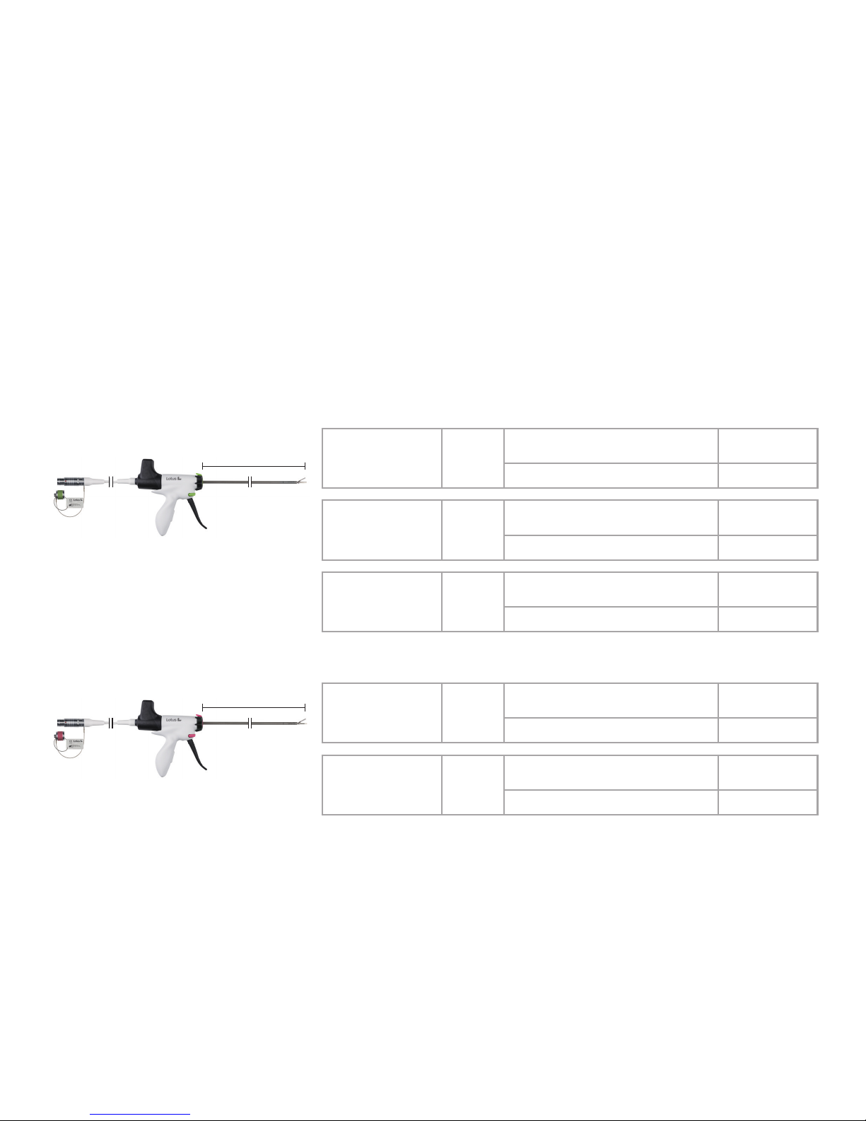
L
LOTUS dissecting shears
LOTUS liver resector
L
TYPE L REF
Open surgery
200,
straight jaw
176 mm
Handpiece
(disposable, 10 per package)
DS4-200SD
Transducer (reusable)
SV3-200
Laparoscopy 400,
curved jaw
349 mm
Handpiece
(disposable, 10 per package)
DS4-400CD
Transducer (reusable)
ES4-400CT*
Bariatric surgery
500,
straight jaw
435 mm
Handpiece
(disposable, 10 per package)
DS4-500SD
Transducer (reusable)
SV3-500
* only for LG4 Series 4 generators with software version Issue 6 or later.
Previous versions must be used with the transducer CV3-400.
TYPE L REF
Open surgery
200,
straight jaw
176 mm
Handpiece
(disposable, 10 per package)
LR4-200SD
Transducer (reusable)
LR3-200
Laparoscopy 400,
straight jaw
349 mm
Handpiece
(disposable, 10 per package)
LR4-400SD
Transducer (reusable)
LR3-400
Page 16

BOWA-QRG-11873-LOTUS-EN-2017-08 Printed in German y We reserve the right to make technical and structural amendments Copyright of BOWA-electronic, Gomaringen
BOWA-electronic GmbH & Co. KG
Heinrich-Hertz-Strasse 4 – 10
72810 Gomaringen I Germany
Phone +49 (0) 7072-6002-0
Fax +49 (0) 7072-6002-33
[email protected] I bowa-medical.com
SRA Developments Ltd
a BOWA-electronic GmbH & Co. KG company
Bremridge House, Bremridge,
Ashburton, Devon, TQ13 7JX, UK
 Loading...